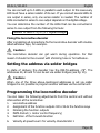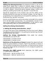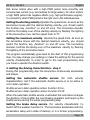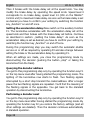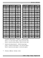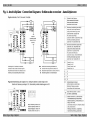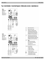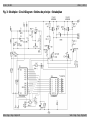
1
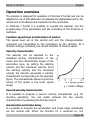
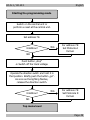
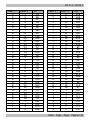
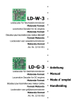
n
LD-W-1
n
Lokdecoder für Wechselstrommotoren
Motorola-Format
n
Locomotive Decoder for AC engines
Motorola-Format
n
Décodeur pour locomotive avec moteur alternatif
Format-Motorola
n
Locdecoder voor wisselstroommotoren
Motorola-format
n
Art.-Nr. 22-01-015-3
n
n
n
n
Anleitung
n
Manual
Lokdecoder für Gleichstrommotoren
Motorola-Format
n
Mode d´emploi
Locomotive Decoder for DC engines
Motorola-Format
n
Handleiding
Décodeur pour locomotive avec moteur continu
Format-Motorola
n
Locdecoder voor gelijkstroommotoren
Motorola-format
n
LD-G-1
Art.-Nr. 22-01-016-3
n
© 11/2004 Tams Elektronik GmbH
Alle Rechte, insbesondere das Recht
der Vervielfältigung und Verbreitung
sowie der Übersetzung vorbehalten.
Vervielfältigungen und Reproduktionen
in jeglicher Form bedürfen der
schriftlichen Genehmigung durch die
Tams Elektronik GmbH.
Technische Änderungen vorbehalten.
© 11/2004 Tams Elektronik GmbH
All rights reserved. No part of this
publication may be reproduced or
transmitted in any form or by any
means, electronic or mechanical,
including photocopying, without prior
permission in writing from Tams
Elektronik GmbH.
Subject to technical modification.
© 11/2004 Tams Elektronik GmbH
Tout droits réservés, en particulier les
droits de reproduction et de diffusion
ainsi que le traduction. Toute
duplication ou reproduction sous
quelque forme que ce soit nécessite
l´accord écrit de la societé Tams
Elektronik GmbH.
Sous
réserve
de
modifications
techniques.
© 11/2004 Tams Elektronik GmbH
Alle rechten voorbehouden. Niets uit
deze
publicatie
mag
worden
vermenigvuldigd
opgeslagen
of
openbaar
gemaakt,
zonder
voorafgaande schriftelijke toestemming
van Tams Elektronik GmbH.
Technische wijzigingen voorbehouden.
n
n
n
n
Deutsch
n
English
31
n
Français
57
n
Nederlands
84
n
n
n
n
n
n
n
n
n
3
LD-G-1 / LD-W-1
English
Table of contents
How to use this manual
32
Intended use
32
Safety instructions
32
EMC declaration
Operation overview
34
35
Technical specifications
38
Checking the package contents
38
Required tools and materials
39
Safe and correct soldering
39
Mounting the locomotive decoder
40
Setting the address via solder bridges
43
Programming the locomotive decoder
43
Operation
54
FAQ
55
Manufacturer's note
55
Certification
56
Conditional warranty
56
Appendix: Check back of the address
Connections (Fig. 1 and Fig. 2)
Circuit Diagram (Fig. 3)
112
I
III
(Pages I to III in the centre of this handbook are removeable.)
* "Märklin" is a registered and protected trade mark of Gebr. Märklin
& Co, Stuttgarter Straße, Göppingen, Germany.
** “Intellibox” is a registered and protected trade mark of
Uhlenbrock Elektronik GmbH, Bottrop, Germany.
Page 31
English
LD-G-1 / LD-W-1
How to use this manual
If you have no specialist technical training, this manual gives step-bystep instructions for safe and correct fitting of the module, and
operation. Before you start, we advise you to read the whole manual,
particularly the chapter on safety instructions and the FAQ chapter. You
will then know where to take care and how to prevent mistakes which
take a lot of effort to correct.
Keep this manual safely so that you can solve problems in the future. If you
pass the module on to another person, please pass on the manual with it.
Intended use
!
Caution:
Integrated circuits are very sensitive to static electricity. Do not touch
components without first discharging yourself. Touching a radiator or
other grounded metal part will discharge you.
The module can be used according to the specifications of this manual in a
model railway locomotive with d.c. motor (LD-G-1) resp. a.c. motor (LD-W-1).
It evaluates the Motorola II format data sent by the digital central unit to its
address. The decoder controls the vehicle performance (velocity, direction
of travel, acceleration) and switches seven function outputs.
The module is not suitable for children under the age of 14. Reading,
understanding and following the instructions in this manual are mandatory
for the user. Any other use is inappropriate and invalidates any guarantees.
Safety instructions
Mechanical hazards
Cut wires can have sharp ends and can cause serious injuries. Watch
out for sharp edges when you pick up the PCB.
Visibly damaged parts can cause unpredictable danger. Do not use
damaged parts: recycle and replace them with new ones.
Page 32
LD-G-1 / LD-W-1
English
Electrical hazards
§
§
§
§
§
§
Touching powered, live components,
touching conducting components which are live due to malfunction,
short circuits,
connecting the circuit to another voltage than specified,
impermissibly high humidity,
condensation build up
can cause serious injury due to electrical shock. Take the following
precautions to prevent this danger:
§
§
§
§
§
§
§
Never perform wiring on a powered module.
Mounting the module should only be done in closed, clean, dry
rooms. Beware of humidity.
Only use low power for this module as described in this manual and
only use certified transformers.
Connect transformers and soldering irons only in approved mains
sockets installed by an authorised electrician.
Observe cable diameter requirements.
After condensation build up, allow a minimum of 2 hours for dispersion.
Use only original spare parts if you have to repair the module.
Fire risk
Touching flammable material with a hot soldering iron can cause fire, which
can result in injury or death through burns or suffocation. Connect your
soldering iron or soldering station only when actually needed. Always keep
the soldering iron away from inflammable materials. Use a suitable
soldering iron stand. Never leave a hot soldering iron or station unattended.
Thermal danger
A hot soldering iron or liquid solder accidentally touching your skin can
cause skin burns. As a precaution:
§
§
§
use a heat-resistant mat during soldering,
always put the hot soldering iron in the soldering iron stand,
point the soldering iron tip carefully when soldering, and
Page 33
English
§
LD-G-1 / LD-W-1
remove liquid solder with a thick wet rag or wet sponge from the
soldering tip.
Dangerous environments
A working area that is too small or cramped is unsuitable and can cause
accidents, fires and injury. Prevent this by working in a clean, dry room
with enough freedom of movement.
Other dangers
Children can cause any of the accidents mentioned above because they
are inattentive and not responsible enough. Children under the age of
14 should not be allowed to work with this module.
Little children can swallow small components with sharp edges, with
fatal results! Do not allow components to reach small children.
Do not allow components to reach small children.
In schools, training centres, clubs and workshops, assembly must be
supervised by qualified personnel.
In industrial institutions, health and safety regulations applying to
electronic work must be adhered to.
EMC declaration
This product is developed in accordance with the European standards
EN 55014 and EN 50082-1, tested corresponding to the EC - directive
89/336/EWG (EMVG of 09/11/1992, electromagnetic tolerance) and
meets legal requirements.
To guarantee the electromagnetic tolerance you must take the
following precautions:
§
§
§
Connect the transformer only to an approved mains socket installed
by an authorised electrician.
Make no changes to the original parts and accurately follow the
instructions, circuit diagram and connections diagrams included
with this manual.
Use only original spare parts if you have to repair the module.
Page 34
LD-G-1 / LD-W-1
English
Operation overview
The decoder is designed for operation in Motorola II format and can be
adjusted to one of 255 addresses. It evaluates the digital data sent by the
central unit to its address and transmits it to the locomotive.
In Motorola I format it is possible to operate the decoder, but the
programming of the parameters and the controlling of the functions is
restricted.
Function speed level and direction of motion
The speed level set at the central unit and the change-direction
command are transmitted to the locomotive by the decoder. At a
direction change command, the current direction of travel is saved.
Velocity characteristic
The decoder can be adjusted to the
individual driving characteristics of the
motor and the characteristic speed of the
locomotive type, by setting the starting
velocity and the maximum velocity. From
the starting velocity and the maximum
velocity the decoder generates a velocity
characteristic corresponding to the opposite
figure. This characteristic allows a good fine
tuning of the speed in the lower speed
range.
x = speed grade
y = motor voltage
Second velocity characteristic
It is possible to program a second velocity characteristic (e.g. for
shunting operation). You can switch between the two velocity
characteristics by operating the function key F4.
Acceleration and brake delay
It is possible to program the acceleration and brake delay individually
via the central unit. When the function F4 is switched on, the
Page 35
English
LD-G-1 / LD-W-1
acceleration and brake delay is deactivated (and simultaneously it
switches over to the second velocity characteristic). Even if the
acceleration and the brake delay are active you can actuate an
emergency stop via the central unit by reversing the direction of travel.
Automatic shuttle service
If the automatic shuttle service is active the locomotive stops with the
set brake delay as soon as the decoder detects a negative direct
voltage on the track (Märklin* braking route). Then the decoder
changes internally the directions of motion „forwards“ and „backwards“.
After the negative direct voltage on the track has been compensated
the locomotive automatically starts with the set acceleration delay in
the opposite direction.
During standard operation it is possible to drive the decoder as usual even
if the automatic shuttle service is active. While the standard operation is
interrupted the decoder maintains it’s present direction of travel.
Function outputs
The decoder has seven function outputs which can be switched on and
off via the function keys „function“ and / or the auxiliary function keys
F1 to F4. They are available to connect optional accessories (e.g.
lighting, smoke generator, sound module, electric coupling).
The set states of the function outputs are saved. Even if the decoder is
without current for a longer time, the states are set when the decoder
is switched on again.
Assignment: The outputs X7 to X10 are assigned to the function
outputs F1 to F4. You can assign the function keys to the function outputs
X4 to X6 freely. It is possible to assign several function keys to these
function outputs. Function outputs that are assigned to the function key
„function“ can be switched according to the direction of travel.
Example of use: The lighting of a shunting locomotive is assigned both
to the function key „function“ as to the function key F4. In shunting
operation you switch the lighting via F4 and in standard operation
according to the direction on travel via „function“.
Page 36
LD-G-1 / LD-W-1
English
Dimming: The function outputs X4 to X6 can be dimmed individually.
Example of use: The electric bulbs of older locomotives made for
analogue operation can be dimmed and thus must not be exchanged
after the mounting of the decoder.
Example of use: The front lighting is assigned to two different function
outputs. Via one function key you can switch the standard lighting, via
another the long distance lighting.
Check back of the address
In the programming mode you can query the address. The address is
transmitted coded by the flashing of the lighting of the locomotive.
Online-programming
The address, the driving characteristics and all functions can be
programmed online. This means:
§
In order to start the programming mode and to set the desired
(new) address, it is not necessary to enter the present address.
§
While programming the driving characteristics (starting and
maximum velocity, acceleration and brake delay) the locomotive is
running. By operating the speed knob the driving characteristics are
altered. As soon as these are set as desired, they can be saved
directly (online).
In the programming mode the function to be set is active. This
makes it easier to assign the outputs to the function keys. The
dimming function can be altered via the speed knob. As soon as it
is set as desired, it can be saved directly (online).
§
Setting the address via solder bridges
It is possible to set four different addresses via solder bridges, as an
alternative to the setting of the address via online-programming. This
possibility is of importance when programming via the central unit is
not possible (e.g. Märklin* DELTA central unit).
Page 37
English
LD-G-1 / LD-W-1
Restrictions in Motorola I format
In Motorola I Format the following settings can be made:
§
§
Address, starting and maximum velocity
assignment of the funciton outputs to „function“
A reset and reading the address is not possible. It is not possible to
program the second velocity characteristic or the acceleration and brake
delay. The functions F1 to F4 cannot be switched.
Technical specifications
Data format
Supply voltage
Current consumption
(without connected loads)
Max. current for motor
Max. current per function output
Max. total current
Protected to
Ambient temperature in use
Ambient temperature in storage
Comparative humidity allowed
Dimensions
Weight
Motorola II
12-24 Volt digital voltage
approx. 10 mA
1.000 mA
500 mA
1.500 mA
IP 00
0 - + 60° C
-10 - + 80° C
max. 85 %
approx. 16,8 x 24 x 4,5 mm
approx. 2 g
Checking the package contents
Check the contents of the package for completeness immediately after
unpacking:
§
§
one decoder, with or without soldered connecting wires, depending
on the version,
one manual.
N.B. For technical reasons it is possible that the PCB is not completely
inserted. This is not a fault.
Page 38
LD-G-1 / LD-W-1
English
Required tools and materials
Make sure you have the following tools, equipment and materials ready
for use:
§
§
§
§
§
§
§
§
an electronic soldering iron (max. 30 Watt) with a fine tip,
a soldering iron stand,
a tip-cleaning sponge,
a heat-resistant mat,
a small side cutter and wire stripper,
a pair of tweezers,
tin solder (0,5 mm. diameter),
wire (diameter: > 0,05 mm² for all connections).
Safe and correct soldering
!
Caution:
Incorrect soldering can cause dangers through fires and heat. Avoid
these dangers by reading and following the directions given in the
chapter Safety instructions. If you have had training in soldering you
can skip this chapter.
§
Use a small soldering iron with max. 30 Watt. Keep the soldering tip
clean so the heat of the soldering iron is applied to the solder point
effectively.
§
Only use tin solder SN 60 Pb (i.e. 60 % tin, 40 % lead) with rosinbased flux.
When soldering electronic circuits never use soldering-water or
soldering grease. They contain acids that can corrode components
and copper tracks.
§
§
Solder quickly: holding the iron on the joints longer than necessary
can destroy components and can damage copper tracks or
soldering eyes.
§
Apply the soldering tip to the soldering spot in such a way that the
wire and the soldering eye are heated at the same time.
Page 39
English
LD-G-1 / LD-W-1
Simultaneously add solder (not too much). As soon as the solder
becomes liquid take it away. Hold the soldering tip at the spot for a
few seconds so that the solder flows into the joint, then remove the
soldering iron.
The joint should be held still for about 5 seconds after soldering. A
glossy and perfect soldering spot should remain.
To make a good soldering joint you should use a clean and
unoxidised soldering tip. Clean the soldering tip with a damp piece
of cloth, a damp sponge or a piece of silicon cloth.
After soldering check (preferably with a magnifying glass) tracks for
accidental solder bridges and short circuits. This would cause faulty
operation or, in the worst case, permanent damage. You can
remove excess solder by putting a clean soldering tip on the spot.
The solder will become liquid again and flow from the soldering
spot to the soldering tip.
§
§
§
Mounting the locomotive decoder
Open the locomotive housing. Locate the position for the decoder.
Disconnect the motor from the rail current collector respectively the
change-over switch from the motor and rail current collector if you have
a locomotive with (electronic) change-over switch. The change-over
switch is no longer necessary, you can reomove it.
!
Caution:
The interference suppression devices mounted to the motor or the
connecting wire must not be removed! Motor and interference
suppression devices are one unit. If even one part is removed, it can
cause extreme interference!
Connecting the LD-G-1
Follow the connections diagrams (fig. 1a and 2a)! Solder the connection
to the slider at point X3, and the connection to the housing to point X2.
These two connections can be exchanged without effecting functionality.
Solder the connections to the motor at the points X11 and X12.
Page 40
LD-G-1 / LD-W-1
English
Connecting the LD-W-1
Follow the connections diagrams (fig. 1a and 2b)! Solder the connection
to the slider at point X3 and the connection to the housing to point X2.
These two connections can be exchanged without effecting
functionality. Solder the connections to the motor at the points X11,
X12 and X13.
Connecting the lighting and other accessories
Disconnect any existing diodes in the leads to the lamps.
Connections to the outputs X7 to X10
The accessories connected to the outputs X7 to X10 are switched via the
function keys F1 to F4. You will find the assignment of the outputs to the
functions keys in the connections diagram Fig. 1.
Connections to the outputs X4 to X6
The accessories connected to the outputs X4 to X6 are assigned freely to
the function keys “function“ and F1 to F4 during the programming of the
decoder. For that reason it is possible to connect the accessories to the
function outputs any way.
If you want to use the decoder factory settings for the outputs X4 to
X6, you have to connect the lighting and the accessories as follows:
Front lighting: X4
Back lighting: X5
Accessory independent of the direction to be switched via „function“: X6
Connections to the return conductor
Follow the connections diagrams (fig. 1a)! If the lamp or the accessory
is already connected with one side to locomotive ground you should
solder a diode between the decoder and the lamp or accessory. If not,
connect the second side of the lamp or the accessory to the return
conductor of the decoder (point X1).
! Caution:
If you connect the loads to the return conductor for all functions (point
Page 41
English
LD-G-1 / LD-W-1
X1), the load must be insulated. The loads should not make contact
with metal parts of the locomotive. Possible short circuit! The
locomotive decoder will be damaged in operation.
!
Caution:
The return conductor for all functions (point X1) must under no
circumstances be connected to locomotive ground. Possible short
circuit! The locomotive decoder will be damaged in operation.
Tip: If the second side of the lamps is connected to locomotive ground
the lamps often flicker in operation. You can avoid the flickering of the
lamps if you connect the second side to the return conductor (point X1)
instead of locomotive ground.
Advice: Before starting to programm the locomotive decoder, you
should connect a lamp to at least one of the function outputs X4 to X6,
as the beginning of the programming mode as well as the entering of
the set parameters is indicated by flashing the locomotive lighting.
Advice: Some accessories can not be checked for operation by
switching on and off in short invervals (e.g. smoke generators). If you
have connected accessories like these to the function outputs X4 to X6
of the decoder it is recommended to connect a lamp in parallel to the
accessory during the programming of the decoder.
Connecting the LEDs
The function outputs of the locomotive decoder switch against decoder
ground. For that reason you must connect the cathode (-) of the LED to
the output of the relevant function.
!
Caution:
If you use light-emitting diodes (LEDs) you must always operate them
via a series resistor.
LEDs are available in many different models. There are LEDs with 2-5
mA, but also LEDs with 15-30 mA power consumption. The series
resistor limits the current flow of the LED and will need to be calculated
for each model. Ask for the max current rating when buying your LEDs.
Page 42
LD-G-1 / LD-W-1
English
You can connect up to 5 LEDs in parallel to each output. In this case every
LED must have a series resistor of its own. If you connect several LEDs to
one output in series, only one series resistor is needed. The number of
LEDs connected in series to one output depends on the digital voltage.
You can determine the number of the LEDs that can be connected in
series to one output from the following formula:
(number of LEDs + 2) x 1,5 < digital voltage
Fixing the locomotive decoder
After completing all connections fix the locomotive decoder with doublesided adhesive tape, for example.
!
Caution:
The locomotive decoder can get warm during operation. For that
reason it should not be covered with shrinking hose or hot adhesive.
Setting the address via solder bridges
In state of delivery the decoder has the DELTA-address „78“. The
addresses 24, 60 and 72 can be set via solder bridges (see fig. 1b).
!
Caution:
When one of the three above-mentioned addresses is set via solder
bridges it is not possible to program another address via the central unit.
Programming the locomotive decoder
You can make the following adjustments from the central unit without
intervention at the locomotive:
1. Locomotive address
2. Assignment of the function outputs X4 to X6 to the function keys
3. Dimming the function outputs
4. PWM-Period (= motor control frequency)
5. Definition of the forward direction
6. Velocity at speed level 1 for velocity characteristic 1
Page 43
English
7.
8.
9.
10.
11.
12.
LD-G-1 / LD-W-1
Maximum speed for velocity characteristic 1
Velocity at speed level 1 for velocity characteristic 2
Maximum speed for velocity characteristic 2
Automatic shuttle service: active or inactive
Acceleration delay for velocity characteristic 1
Brake delay for velocity characteristic 1
Accessing the programming mode
Put the vehicle on to a programming track or on the layout and reset
the central unit (by simultaneously pushing the buttons “stop” and “go”
for some time). Enter the address "78" at the central unit. Set the
function key "function" of the central unit to "off".
!
Attention:
It does not matter if you have already saved another address. You
always have to enter the address "78" to access the programming
mode. If you put the vehicle for programming on the layout take off all
other vehicles with deocders with online-programming. If not you
programm these vehicles as well.
Push the "stop" button at the central unit. Next, operate the direction switch
and hold it in that position while briefly pushing the "go" button. As soon as
the lamps connected to the outputs X4 to X6 flash (after approx. 2 seconds)
you are in the programming mode and can release the direction switch.
Notice: Some types of central units do not allow you to access to the
programming mode when the Motorola II format is set (e.g.
Intellibox** from Uhlenbrock). In order to start the programming
mode these central units must be set to Motorola I format for the
address “78”. As soon as the decoder is in the programming mode, the
central unit must be set back to Motorola II format.
Starting from this menu level you can:
Without any further inputs: Set the address and the functions.
After pushing the function key F1: Query the address.
After pushing the function key F2: Perform a decoder reset.
After pushing the function key F3: Set the driving characteristics.
Page 44
LD-G-1 / LD-W-1
English
You can finish the programming mode at any time by disconnecting the
vehicle (pushing the button „stop“ or taking the vehicle from the track).
Setting the locomotive address and the functions
1. Setting the locomotive address
You are in the menu point „Setting the locomotive address“ when all
lighting connected to the function outputs X4 to X6 flash regularly.
Enter the desired address. You do not need to enter the old address.
Confirm your setting by switching the function key „function” on and off
once. After the taking-over of the locomotive address the regular
flashing of the connected lighting stops and the decoder proceeds
immediately to the programming of the first function output.
2. Setting the function outputs
Now the function outputs X4, X5 and X6 are programmed one after the
other. The function keys are assigned in succession, and the dimming
function is set for each output.
Assigning the function keys: While the programm continuously
switches the ouput to be programmed on and off (and the lighting
connected to the output flashes) switch on the functions key(s) F1 to F4 on
your central unit with which you want to switch the output in later
operation. You can assign several function keys to one output of the
decoder. Please notice that in operation the second velocity characteristic is
activated and the acceleration and brake delay is deactivated via F4.
If you want to switch the function output in operation via „function“ you
have to make the following settings:
Speed level 1 : Output will be switched on during backwards motion.
Speed level 2 : Output will be switched on during forward motion.
Speed level 3 : Output will be switched on independent of the direction
of motion.
Advice: On the Märklin* Central Unit 6021 the speed levels 1,2 and 3
correspond to the settings 20, 40 and 60.
Confirm your settings by switching the function key „function“ on and
off once.
Page 45
English
LD-G-1 / LD-W-1
Setting the dimming function: The dimming function is set via the
speed knob. Speed level 0 stands for minimal voltage (if lamps are
connected minimal brightness) at the output to be set and speed level
14 (250 on Märklin* Control Unit 6021) maximal voltage. Confirm your
setting by switching the function key „function“ on and off once.
Repeat the assignment of the function keys and the setting of the
dimming function for the other two function outputs. You can skip the
programming of an output that is not occuppied by switching on and off
the function key „function“ two times.
As soon as all functions are set the the lamps connected to the outputs
X4 to X6 flash flash several times. You automatically proceed to the
menu point „Setting the driving characteristics“. If you want to close
the programming mode you just disconnect the locomotive.
Setting the driving characteristics
1. Setting the driving characteristics - step 1
You get to this menu point automatically from the menu point „Setting
the address and the functions“ or by pushing the function key F3 when
entering the top menu level.
Setting the driving characteristic: First select the velocity
characteristic you want to set:
Characteristic 1: Function F4 off.
Characteristic 2: Function F4 on.
Definition of the direction of travel: Operate the speed knob and
check the actual direction of travel. Check if the direction of travel of
the locomotive corresponds to the direction of travel set at the central
unit. If the actual and the set direction do not correspond operate the
function key „F2“.
Choosing the PWM period: Next determine the PWM period
(= motor control frequency).
PWM period = 125 Hz: function F1 off.
PWM period = 1800 Hz: function F1 on.
Page 46
LD-G-1 / LD-W-1
English
N.B. Some motors drive with a high PWM period more smoothly and
consume less current (e.g. locomotives for large scales). On other motors
a high PWM period has negative effects (e.g. high-performance engine).
You should try which PWM period is the right one in the individual case.
Setting the starting velocity: Operate the speed knob. As soon as the
locomotive moves with the desired starting velocitiy, you should switch
the function key „function” on and off once. The locomotive decoder
confirms the taking-over of the starting velocity by flashing the lighting
of the locomotive once. Set the speed knob to "0".
Setting the maximum velocity: Operate the speed knob. As soon as
the locomotive moves with the desired maximum velocity, you should
switch the function key „function“ on and off once. The locomotive
decoder confirms the taking-over of the maximum velocity by flashing
the lighting of the locomotive twice.
The program automatically goes back to the start of this programming
step. You may change your settings or make the settings for the second
velocity characteristic. In order to get to the next programming step
you have to operate the direction switch.
2. Setting the driving characteristics - step 2
During this programming step the locomotive continuously accelerates
and brakes.
Setting the automatic shuttle service (for both velocity
characteristics): Set if the automatic shuttle service is to be active or
not in later operation.
Shuttle servie in later operation active: Function F3 on.
Shuttle servie in later operation active: Function F3 off.
When the automatic shuttle service is activated the locomotive changes
the direction of travel after the next braking operation and keeps up the
shuttle service during the whole programming step.
Setting the brake delay service (for velocity characteristic 1):
Switch off the auxiliary function F1. The locomotive accelerates with the
acceleration delay set in state of delivery or in a former programming.
Page 47
English
LD-G-1 / LD-W-1
Then it brakes with the brake delay set at the speed knob. You may
modify the brake delay by operating the speed knob. Speed level 0
corresponds to no brake delay, speed level 14 (250 on the Märklin*
Control unit) to maximum brake delay. As soon as the brake delay is set
as desired you have to confirm your setting by switching the function
key „function“ on and off once.
Setting the acceleration delay: Now switch on the auxiliary function
F1. The locomotive accelerates with the acceleration delay set at the
speed knob and then brakes with the brake delay set before. Continue
as described in section: „Setting the brake delay“. As soon as the
acceleration delay is set as desired you have to confirm your setting by
switching the function key „function“ on and off once.
During this programming step you may switch the automatic shuttle
service on or off as required by operating F3 and also change between
setting the brake or the acceleration delay by operating F1.
When all settings are made, you close the programming mode by
disconnecting the decoder (pushing the button „stop“ or taking the
locomotive from the track).
Querying the decoder address
You get to this programming step only by operating the function key F1
on the top menu level after having started the programming mode. The
lighting of the locomotive now starts to flash. Two flashing signals
interrupted by a short stop transmit the coded address. After a longer
pause the two flashing signals are repeated. You’ll find the meaning of
the flashing signals in the appendiix. You get back to the standard
operation by disconnecting the locomotive.
Performing a decoder reset
You get to this programming step only by operating the function key F2
on the top menu level after having started the programming mode. By
operating the function key F2 you restore the factory settings (and all
other settings are deleted). Then the decoder continues automatically
in standard operation.
Page 48
LD-G-1 / LD-W-1
English
Starting the programming mode
Switch on the central unit or
perform a reset at the central unit.
Set address 78.
Intellibox?
YES
For address 78:
Set Motorola I
format.
NO
Push button „stop“
à Switch off the track voltage.
Operate the direction switch and hold it in
that position. Briefly push the button „go“.
As soon as the lighting flashes,
release the direction switch.
Intellibox?
YES
For address 78:
Set Motorola II
format.
NO
Top menu level
Page 49
English
LD-G-1 / LD-W-1
Top menu level
Setting the address
and the functions.
F3
Setting the driving
characteristics.
Disconnect the loco.
F1
Querying the
decoder address.
Disconnect the loco.
F2
Page 50
Performing a
decoder reset.
Closing the programming mode.
Disconnect the loco.
LD-G-1 / LD-W-1
English
Setting the locomotive
address and the functions
Assign the function keys:
Switch on the function keys
F1, F2, F3 and / or F4.
Assign „function“:
level 1: backward direction
level 2: forward direction
level 3: independent
Enter the desired
locomotive address.
function „on/off“
function „on/off“
Setting the
function outputs X4 – X6
Set the dimming function:
level 0: minimum voltage
level 14: maximum voltage
function „on/off“
NO
Setting the driving
characteristics
Last
function output
set?
YES
Page 51
English
LD-G-1 / LD-W-1
Setting the driving
characteristics step 1
For which
characteristic
?
2
1
F4 „off“
function „on/off“
F4 „on“
Operate speed knob.
Set maximum speed.
Operate speed knob.
Direction of travel
o.k.?
YES
PWM high /
low?
HIGH
F1 „on“
Page 52
Operate speed knob.
Set starting speed.
NO
function „on/off“
F2
Operate
direction switch.
LOW
F1 „off“
Setting the driving
characteristics step 2
LD-G-1 / LD-W-1
English
Setting the driving
characteristics step 2
Shuttle service
on / off?
OFF
ON
F3 „on“
F3 „off“
F1 „off“
Operate speed knob.
Set brake delay.
Level 0: No brake delay.
Level 14: maximum brake delay.
F1 „on“
Operate speed knob.
Set acceleration delay.
Level 0: No acceleration delay.
Level 14: maximum acceleration delay.
Disconnect the loco.
Closing the
programming mode
Page 53
English
LD-G-1 / LD-W-1
Operation
Acceleration and brake delay / Second velocity characteristic
In Motorola II format you can switch the acceleration and brake delay
on or off and you can switch between the two velocity characteristics
via F4.
F4 off: Delay active and characteristic 1 set.
The setting is immediately active.
In Motorola I format you cannot switch the acceleration and brake
delay on or off and you cannot switch to the second velocity
characteristic. The acceleration and brake delay is always active.
An emergency stop can be made via the central unit by reversing the
direction.
Improvement of the driving characteristics
Locomotives with especially high current consumption or track sections
with bad contacts (e.g. some types of points) may give an
unsatisfactory performance. You can improve the locomotive
performance by soldering a capacitor 100 µF / 35 V between X16 and
X17 (see fig. 2a resp. 2b).
Analogue mode
In analogue mode the decoder can be run like a change-over switch. This
means the decoder reacts with a change of direction on the shift impulse
of the speed control knob, as usual. In analogue mode the lighting and
the accessory connected to X6 are always switched on.
The lighting is switched depending on the direction of travel.
You access the analogue mode by pressing the direction switch of the
analogue driving transformer until the light of the locomotive starts flashing.
To get back into the digital mode, press the direction switch of the analogue
driving transformer again until the light of the locomotive starts to flash.
Page 54
LD-G-1 / LD-W-1
English
FAQ
§
Parts are getting too hot and/or start to smoke.
§
Possible cause: one or more connections are soldered incorrectly.
à Check the connections.
Possible cause: The connection of the motor is connected to locomotive
ground. à Disconnect the connection from locomotive ground.
A lamp flickers (this is not a defect).
§
Possible cause: The lamp is connected with one side to locomotive
ground. à If you do not want the lamp to flicker, disconnect it from
locomotive ground, insulate it and connect it to the return
conductor (point X1).
The locomotive runs too slowly or too fast.
!
Disconnect the system from the mains immediately!
Possible cause: Different locomotives react in different ways to
identical programmings. à Adapt the programming to the
individual characteristics of the locomotive.
§ The locomotive does not react to F4.
Possible cause: Instead of Motorola II format, Motorola I format is
set at the central unit. à Set Motorola II format.
If you cannot find the problem, please return the decoder for repair
(address on the cover page).
Manufacturer's note
According to DIN VDE 0869, the person who brings the circuit into
operation by extension resp. mounting into a housing is the
manufacturer of the product. If he sells the product to another person
he is responsible for passing on all the relevant papers and to give his
name and address.
Page 55
English
LD-G-1 / LD-W-1
Certification
This product conforms with the EC- directive 89/336/EWG on
electromagnetic radiation and is therefore CE certified.
Conditions of warranty
This product is guaranteed for two years. The warranty includes the
correction of faults which can be proved to be due to material failure or
factory flaw. We guarantee the adherence to the technical
specifications of the circuit when assembled and connected according to
the manual.
Other claims are excluded. By law, we are not responsible for damages
or secondary damages in connection with this product. We retain the
right to repair, make improvements, supply spare parts or return the
purchase price.
The following invalidate the warranty:
§ using an unsuitable soldering iron, solder containing liquid acids or
similar,
§ if damage is caused by not following the instructions in this manual
or the connection diagram(s),
§ if the module has been altered and repair attempts have failed,
§ if arbitrary changes in the circuit are made,
§ additional components are added which are not described in the
manual,
§ if the copper tracks or soldering eyes are damaged,
§ if damage occurs due to an overload of the module,
§ if connected to a incorrect voltage or current,
§ if damaged by other persons,
§ if damaged by faulty operation or if damaged by careless use or
abuse,
§ if damaged by touching components before electrostatic
discharging of the hands.
Page 56
LD-G-1 / LD-W-1
Tabelle: Rückmeldung der Decoderadresse
Appendix: Check back of the address
Tableau : Indiquation de l´adresse du décodeur
Tabel: Terugmelding van het decoderadres
Flash 1 *
1
1
1
1
1
1
1
1
1
1
1
1
1
1
1
1
2
2
2
2
2
2
2
2
2
2
2
2
2
2
2
2
Flash 2 *
1
2
3
4
5
6
7
8
9
10
11
12
13
14
15
16
1
2
3
4
5
6
7
8
9
10
11
12
13
14
15
16
Ad. **
80
2
81
1
6
8
82
7
145
177
191
161
3
5
84
4
18
20
85
19
24
26
86
25
146
178
87
162
21
23
88
22
Seite - Page - Page - Pagina 112
Flash 1 *
3
3
3
3
3
3
3
3
3
3
3
3
3
3
3
3
4
4
4
4
4
4
4
4
4
4
4
4
Flash 2 *
1
2
3
4
5
6
7
8
9
10
11
12
13
14
15
16
1
2
3
4
5
6
7
8
9
10
11
12
Ad. **
193
201
89
197
217
225
90
221
147
179
91
163
205
213
92
209
9
11
93
10
15
17
94
16
148
180
95
164
4
4
13
14
12
14
4
4
15
16
96
13
LD-G-1 / LD-W-1
Flash 1 *
5
5
5
5
5
5
5
5
5
5
5
5
5
5
5
5
6
6
6
6
6
6
6
6
6
6
6
6
6
6
6
6
7
7
7
7
Flash 2 *
1
2
3
4
5
6
7
8
9
10
11
12
13
14
15
16
1
2
3
4
5
6
7
8
9
10
11
12
13
14
15
16
1
2
3
4
Ad. **
54
56
97
55
60
62
98
61
149
181
99
165
57
59
100
58
72
74
101
73
78
--102
79
150
182
103
166
75
77
104
76
194
202
105
198
Flash 1 *
7
7
7
7
7
7
7
7
7
7
7
7
8
8
8
8
8
8
8
8
8
8
8
8
8
8
8
8
Flash 2 *
5
6
7
8
9
10
11
12
13
14
15
16
1
2
3
4
5
6
7
8
9
10
11
12
13
14
15
16
Ad. **
218
226
106
222
151
183
107
167
206
214
108
210
63
65
109
64
69
71
110
70
152
184
111
168
66
68
112
67
9
9
9
9
9
9
9
9
1
2
3
4
5
6
7
8
229
231
113
230
235
237
114
236
Seite - Page - Page - Pagina 113
LD-G-1 / LD-W-1
Flash 1 *
Flash 2 *
Ad. **
9
9
9
10
153
185
9
9
9
9
9
9
10
10
10
10
10
10
10
10
10
10
10
10
10
10
10
10
11
11
11
11
11
11
11
11
11
11
11
11
11
12
13
14
15
16
1
2
3
4
5
6
7
8
9
10
11
12
13
14
15
16
1
2
3
4
5
6
7
8
9
10
11
12
115
169
232
234
116
233
247
249
117
248
253
255
118
254
154
186
119
170
250
252
120
251
195
203
121
199
219
227
122
223
155
187
192
171
Seite - Page - Page - Pagina 114
Flash 1 *
11
11
11
11
12
12
12
12
12
12
12
12
12
12
12
12
12
12
12
12
13
13
13
13
13
13
13
13
13
13
13
13
13
13
13
13
Flash 2 *
13
14
15
16
1
2
3
4
5
6
7
8
9
10
11
12
13
14
15
16
1
2
3
4
5
6
7
8
9
10
11
12
13
14
15
16
Ad. **
207
215
124
211
238
240
125
239
244
246
126
245
156
188
127
172
241
243
128
242
27
29
129
28
33
35
130
34
157
189
131
173
30
32
132
31
LD-G-1 / LD-W-1
Flash 1 *
14
14
14
14
14
14
14
14
14
14
14
14
14
14
14
14
15
15
15
15
15
15
15
15
*
Flash 2 *
1
2
3
4
5
6
7
8
9
10
11
12
13
14
15
16
1
2
3
4
5
6
7
8
Ad. **
45
47
133
46
51
53
134
52
158
190
135
174
48
50
136
49
196
204
137
200
220
228
138
224
Flash 1 *
15
15
15
15
15
15
15
15
16
16
16
16
16
16
16
16
16
16
16
16
16
16
16
16
Flash 2 *
9
10
11
12
13
14
15
16
1
2
3
4
5
6
7
8
9
10
11
12
13
14
15
16
Ad. **
159
83
139
175
208
216
140
212
36
38
141
37
42
44
142
43
160
123
143
176
39
41
144
40
Anzahl der Blinkzeichen / Number of flashing signals
Flash 1: vor der kurzen Pause / before the short stop
Flash 2: nach der kurzen Pause / after the short stop
*
Nombre des clignotements / Aantal knipperingen
Flash 1: avant la courte pause / voor de korte pauze
Flash 2: après la courte pause / na de korte pauze
**
Adresse / address / adresse / adres
Seite - Page - Page - Pagina 115
LD-G-1 / LD-W-1
LD-G-1 / LD-W-1
Fig. 1: Anschlußpläne - Connection Diagrams - Schémas de connexion - Aansluitplannen
Seite - Page - Page - Pagina I
Seite - Page - Page - Pagina I
LD-G-1 / LD-W- 1
LD-G-1 / LD-W- 1
Fig. 2: Anschlußpläne - Connection Diagrams - Schémas de connexion - Aansluitplannen
Seite - Page - Page - Pagina II
Seite - Page - Page - Pagina II
LD-G-1 / LD-W-1
LD-G-1 / LD-W-1
Fig. 3: Schaltplan - Circuit Diagram - Schéma de principe - Schakelplan
Seite - Page - Page - Pagina III
Seite - Page - Page - Pagina III
n
n
n
Aktuelle Informationen und Tipps:
Information and tips:
Informations et conseils:
Actuele informatie en tips:
http://www.tams-online.de
n
n
n
n
n
n
Garantie und Service:
Warranty and service:
Garantie et service:
Garantie en service:
n
n
n
Tams Elektronik GmbH
Rupsteinstraße 10
D-30625 Hannover
fon: +49 (0)511 / 55 60 60
fax: +49 (0)511 / 55 61 61
e-mail: [email protected]
n
n
n
n