1
ew300_350_IEM_INT.book Seite 1 Freitag, 7. März 2008 8:55 08
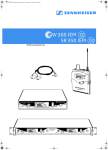
W 300 IEM
SR 350 IEM
Instructions for use
ew300_350_IEM_INT.book Seite 44 Freitag, 7. März 2008 8:55 08
ew300_350_IEM_INT.book Seite 1 Freitag, 7. März 2008 8:55 08
Contents
Important safety instructions ....................................................................................... 2
The ew 300 IEM G2 systems .......................................................................................... 4
The channel bank system .............................................................................................
5
Delivery includes ................................................................................................................ 5
Overview of operating controls .................................................................................... 6
Stereo transmitter – front view (SR 350 IEM G2 twin transmitter) ....................
Stereo transmitter – rear view ....................................................................................
EK 300 IEM G2 stereo receiver .....................................................................................
Indications and displays on the transmitter .............................................................
Indications and displays on the receiver ...................................................................
Preparing the devices for use .......................................................................................
SR 300 IEM G2 transmitter/
SR 350 IEM G2 twin transmitter ..................................................................................
Changing the transmission power (SR 350 IEM G2 only) .......................................
EK 300 IEM G2 receiver ..................................................................................................
Using the components .....................................................................................................
Switching the components on/off ..............................................................................
Adjusting the volume ....................................................................................................
Adjusting the balance ....................................................................................................
Activating/deactivating the lock mode .....................................................................
Attaching the receiver to clothing ..............................................................................
The operating menu .........................................................................................................
The buttons .....................................................................................................................
Overview of menus .........................................................................................................
Working with the operating menu .............................................................................
Operating menu of the stereo transmitter ................................................................
Operating menu of the stereo receiver ......................................................................
Adjustment tips for the operating menu .................................................................
Switching between channel banks .............................................................................
Switching between the channels in a channel bank ...............................................
Selecting the frequencies to be stored
in the channel bank “U” ................................................................................................
Scanning the channel banks for free channels
(receiver only) .................................................................................................................
Multi-channel operation ................................................................................................
Adjusting the squelch threshold (receiver only) ......................................................
Stereo/FOCUS selection (receiver only) .....................................................................
Limiting the volume at the headphone output
(receiver only) .................................................................................................................
Activating/deactivating the frequency boost
(receiver only) .................................................................................................................
Adjusting the sensitivity (transmitter only) ............................................................
Selecting the standard display ....................................................................................
Entering names ...............................................................................................................
Loading the factory-preset default settings .............................................................
Activating/deactivating the pilot tone evaluation (receiver only) ......................
Adjusting the contrast of the graphic display (transmitter only) .......................
Stereo/mono selection (transmitter only) ................................................................
Activating/deactivating the lock mode .....................................................................
Exiting the operating menu ..........................................................................................
If a problem occurs ... .......................................................................................................
Error checklist ..................................................................................................................
Recommendations and tips ..........................................................................................
Care and maintenance .....................................................................................................
Additional information ....................................................................................................
HDX noise reduction .......................................................................................................
Wireless transmission systems ...................................................................................
Squelch .............................................................................................................................
Specifications ......................................................................................................................
Connector assignment ...................................................................................................
Accessories and spare parts ..........................................................................................
Manufacturer Declarations ............................................................................................
6
7
8
9
9
11
11
15
17
18
18
19
19
19
19
20
20
21
21
23
25
28
28
28
28
28
29
29
30
30
30
30
31
32
32
32
32
33
33
33
34
34
35
35
36
36
36
37
38
39
40
41
Thank you for choosing Sennheiser!
We have designed this product to give you reliable operation over many years. Over 60 years
of accumulated expertise in the design and manufacture of high-quality electro-acoustic
equipment have made Sennheiser a world-leading company in this field.
Please take a few moments to read these instructions carefully, as we want you to enjoy your
new Sennheiser products quickly and to the fullest.
1
ew300_350_IEM_INT.book Seite 2 Freitag, 7. März 2008 8:55 08
Important safety instructions
1.
Read these instructions.
2.
Keep these instructions. Always include these instructions when passing
the devices on to third parties.
3.
Heed all warnings.
4.
Follow all instructions.
5.
Do not use the devices near water.
6.
Clean only with a dry cloth.
7.
Do not block any ventilation openings. Install in accordance with these
instructions.
8.
Do not install near any heat sources such as radiators, heat registers,
stoves, or other devices (including amplifiers) that produce heat.
9.
The devices should be operated only from the type of power source
indicated on the mains plug. The devices must only be connected to
properly grounded power outlets.
10. Protect the mains cable from being walked on or pinched, particularly at
plugs, convenience receptacles, and the point where they exit from the
device.
11. Only use attachments/accessories specified by Sennheiser.
12. Use only with the cart, stand, tripod, bracket, or table specified by the
manufacturer, or sold with the device. When a cart is used, use caution
when moving the cart/apparatus combination to avoid injury from tipover.
13. Unplug the devices during lightning storms or when unused for long
periods of time.
14. Refer all servicing to qualified service personnel.
Servicing is required if the device has been damaged in any way, such as
mains cable or plug damage, liquid has been spilled, objects have fallen
inside, the device has been exposed to rain or moisture, does not
operate properly or has been dropped.
15. To completely disconnect the devices from the AC mains, disconnect the
mains plug from the AC receptacle.
16. WARNING: To reduce the risk of fire or electric shock, do not expose the
devices to rain or moisture.
17. Do not expose the devices to dripping or splashing and ensure that no
objects filled with liquids, such as vases or coffee cups, are placed on the
devices.
18. The plug of the mains cable shall remain readily operable and easily
accessible.
2
ew300_350_IEM_INT.book Seite 3 Freitag, 7. März 2008 8:55 08
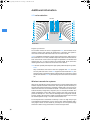
Hazard warnings on the rear of the transmitter (SR 350 IEM G2 only)
The label shown on the left is attached to the rear of the transmitter. The
symbols on this label have the following meaning:
This symbol is intended to alert the user to the presence of uninsulated
dangerous voltage within the transmitter’s enclosure that may be of
sufficient magnitude to constitute risk of fire or electric shock.
This symbol is intended to alert the user to the risk of electric shock if the
transmitter is opened. There are no user serviceable parts inside. Refer
servicing to qualified personnel only.
This symbol is intended to alert the user to the presence of important
operating and maintenance instructions in the literature accompanying this
transmitter.
Overloading
Do not overload wall outlets and extension cables as this may result in fire
and electric shock.
Replacement parts
When replacement parts are required, be sure the service technician has used
replacement parts specified by Sennheiser or those having the same
characteristics as the original part. Unauthorized substitutions may result in
fire, electric shock, or other hazards.
Safety check
Upon completion of any service or repairs to this device, ask the service
technician to perform safety checks to determine that the device is in safe
operating order.
Danger due to high volumes
This is a professional transmission system. Commercial use is subject to the
rules and regulations of the trade association responsible. Sennheiser, as the
manufacturer, is therefore obliged to expressly point out possible health risks
arising from use.
This system is capable of producing sound pressure exceeding 85 dB(A).
85 dB(A) is the sound pressure corresponding to the maximum permissible
volume which is by law (in some countries) allowed to affect your hearing for
the duration of a working day. It is used as a basis according to the
specifications of industrial medicine. Higher volumes or longer durations can
damage your hearing. At higher volumes, the duration must be shortened in
order to prevent hearing damage. The following are sure signs that you have
been subjected to excessive noise for too long a time:
y You can hear ringing or whistling sounds in your ears.
y You have the impression (even for a short time only) that you can no longer
hear high notes.
Reception interference due to high transmission power
The SR 350 IEM G2 twin transmitter can be switched to a transmission power
of 100 mW. Depending on the selected frequency, this can affect the
reception of other wireless systems.
3
ew300_350_IEM_INT.book Seite 4 Freitag, 7. März 2008 8:55 08
Intended use of the devices
Intended use of the ew 300 IEM G2 series devices includes:
y using the devices for professional purposes,
y having read these instructions especially the chapter “Important safety
instructions” on page 2,
y using the devices within the operating conditions and limitations described
in this instruction manual.
“Improper use” means using the devices other than as described in these
instructions, or under operating conditions which differ from those described
herein.
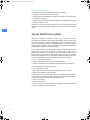
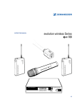
The ew 300 IEM G2 systems
With the Sennheiser evolution wireless in-ear monitoring systems
ew 300 IEM G2 (suitable for both stage and broadcast use), musicians, video
and sound amateurs, reporters/broadcasters, etc. can directly monitor the
received sound signals without troublesome cables or monitor speakers
being required. In addition, the system can also be used for any application
where talkback signals are to be transmitted.
The evolution wireless in-ear monitoring systems ew 300 IEM G2 are highquality state-of-the-art RF transmission systems with a high level of
operational reliability and ease of use. The transmitters and the receiver
permit wireless transmission with studio-quality sound. The excellent
transmission reliability of the ew 300 IEM G2 systems is based on the use of
y further optimized PLL synthesizer and microprocessor technology,
y the HDX noise reduction system,
y the pilot tone squelch control (during stereo operation),
y and the scan function for scanning the channel banks for free channels.
The ew 300 IEM series offers two systems:
y the ew 300 IEM G2 system
(SR 300 IEM G2 stereo transmitter, EK 300 IEM G2 stereo receiver)
y and the SR 350 IEM G2 twin transmitter
The EK 300 IEM G2 can also be used with the SR 350 IEM G2 twin transmitter.
The SR 350 IEM G2 twin transmitter consists of two complete SR 300 IEM G2
stereo transmitters, but offers some advantages such as
y easy rack mounting,
y a built-in mains unit
y and a switchable transmission power for optimum operational reliability
under varying transmission conditions.
4
ew300_350_IEM_INT.book Seite 5 Freitag, 7. März 2008 8:55 08
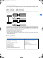
The channel bank system
The ew 300 IEM G2 systems are available in six UHF frequency ranges with 1440 transmission/receiving frequencies
per frequency range. Please note: Frequency usage is different for each country. Your Sennheiser agent will have all
the necessary details on the available legal frequencies for your area:
Range A: 518 to 554 MHz
Range D: 786 to 822 MHz
Range B: 626 to 662 MHz
Range E: 830 to 866 MHz
Range C: 740 to 776 MHz
Range G: 572 to 608 MHz
The transmitters and the receiver of the ew 300 IEM G2 systems have nine channel banks with up to 12 switchable
channels each.
Channel 1
Factory-preset frequency
Channel 2
Factory-preset frequency
Channel 12
Factory-preset frequency
Channel 1
selectable frequency
Channel 2
selectable frequency
Channel 12
selectable frequency
Bank 1...8
Bank U
The channel banks “1” to “8” have up to 12 switchable channels that are factory-preset to a transmission/receiving
frequency (see enclosed frequency table). These transmission/receiving frequencies cannot be changed but have
been preset so that e.g. country-specific regulations on frequency usage are taken into account (see “Type
approvals” on page 39). For detailed information, please refer to the enclosed frequency data sheets and to the
country-specific frequency and transmission power overviews.
An advantage of the factory-preset frequencies is that
y the system is ready for immediate use after switch-on,
y several transmission systems can be operated simultaneously on the preset channels without causing
intermodulation interference.
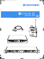
Delivery includes
Depending on the purchased system, delivery includes:
ew 300 IEM G2 system
SR 350 IEM G2
y 1 EK 300 IEM G2 stereo receiver
y 1 SR 350 IEM G2 stereo twin transmitter
y 1 SR 300 IEM G2 stereo transmitter
y 2 telescopic antennas for SR 350 IEM G2
y 2 batteries
y 1 mains cable
y 1 telescopic antenna for SR 300 IEM G2
y Instructions for use
y 1 NT 2-1 mains unit
y 1 frequency data sheet
y 1 pair of IE 4 earphones
y Frequency and transmission power overviews
y Instructions for use
y 1 frequency data sheet
y Frequency and transmission power overviews
5
ew300_350_IEM_INT.book Seite 6 Freitag, 7. März 2008 8:55 08
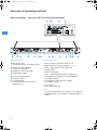
Overview of operating controls
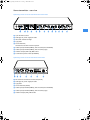
Stereo transmitter – front view (SR 350 IEM G2 twin transmitter)
Operating controls
Graphic display panel
Rack mount “ears”
(preinstalled with the SR 350 IEM G2 only)
Display for the current channel bank “1...8, U”
Headphone output (PHONES),
¼” (6.3 mm) jack socket
“B.CH“ – abbreviation for channel bank and
channel number
Headphone volume control (VOL)
Graphic display, backlit
/ rocker button, backlit
SET button, backlit
ON button, backlit
(serves as the ESC (cancel) key in the
operating menu)
Display for the current channel number “1 ... 12”
Alphanumeric display
“MHz“ – appears when the frequency is displayed
Level display for audio signal “AF I” (left and MONO),
with “PEAK” warning
Level display for audio signal “AF II” (right),
with “PEAK” warning
Lock mode icon
(lock mode is activated)
Note:
For further illustrations and examples of the different
standard displays, see “Selecting the standard display” on
page 31.
6
ew300_350_IEM_INT.book Seite 7 Freitag, 7. März 2008 8:55 08
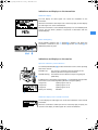
Stereo transmitter – rear view
Operating controls on the SR 350 IEM G2 twin transmitter
3-pin IEC mains socket
Cable grip for power supply DC cable
Label with hazard warnings
Type plate
Service interface;
connection to the NET 1 network system
Audio input (AF IN BAL/UNBAL), XLR-3F socket (left and MONO)
Audio input (AF IN BAL/UNBAL), XLR-3F socket (right)
Antenna output (ANT A/B), BNC socket
Transmission power switch (RF POWER)
Operating controls on the SR 300 IEM G2 transmitter
DC socket for connection of mains unit (DC IN)
Cable grip for power supply DC cable
Type plate
Service interface (DATA)
Audio input (AF IN BAL/UNBAL), XLR-3F socket (left and MONO)
Audio input (AF IN BAL/UNBAL), XLR-3F socket (right)
Antenna output (ANT), BNC socket
7
ew300_350_IEM_INT.book Seite 8 Freitag, 7. März 2008 8:55 08
EK 300 IEM G2 stereo receiver
Operating controls
LC display panel
Headphone output (PHONES), 3.5 mm jack socket
Alphanumeric display
Antenna
“B.CH“ – appears when the channel bank and
the channel number are displayed
Red LED for operation and
battery status indication (ON/LOW BAT)
“MHz“ – appears when the frequency is displayed
Green LED for RF signal indication (RF)
4-step battery status display
Charging contacts
Lock mode icon
(lock mode is activated)
SET button
/ rocker button (DOWN/UP)
Battery compartment
“PILOT” display
(pilot tone evaluation is activated)
Battery compartment cover
“MUTE” display
(audio output is muted)
Battery compartment release button
7-step level display for received audio signal “AF”
ESC button
LC display
On/off/volume control
8
7-step level display for received RF signal “RF”
ew300_350_IEM_INT.book Seite 9 Freitag, 7. März 2008 8:55 08
Indications and displays on the transmitter
Modulation display
The level display for audio signal “AF” shows the modulation of the
transmitter.
When the transmitter’s audio input level is excessively high, the level display
for audio signal “AF” shows full deflection.
When the transmitter is overmodulated frequently or for an extended period
of time, the text “PEAK” (backlit in red) flashes in alternation with the
standard display.
Button backlighting
During standby operation, the ON button is backlit in red. When the
transmitter is switched on, the SET button and the / button ! are
additionally backlit in green.
Indications and displays on the receiver
Operation and battery status indication
The red LED (LOW BAT/ON) provides information on the current operating
state of the receiver:
Red LED lit up:
Red LED flashing:
The receiver is switched on and the capacity of the
batteries/BA 2015 accupack is sufficient.
The batteries are/the BA 2015 accupack is going flat
(LOW BAT)!
In addition, the 4-step battery status display on the display panel provides
information on the remaining battery/BA 2015 accupack capacity:
3 segments:
2 segments:
1 segment:
Battery icon flashing:
capacity approx. 100 %
capacity approx. 70 %
capacity approx. 30 %
LOW BAT
Modulation display of the received transmitter
The level display for audio signal “AF” shows the modulation of the received
transmitter.
When the transmitter’s audio input level is excessively high (AF peak), the
receiver’s level display for audio signal “AF” shows full deflection.
9
ew300_350_IEM_INT.book Seite 10 Freitag, 7. März 2008 8:55 08
“MUTE” display
The “MUTE” display appears on the display panel when the RF signal of the
received transmitter is too weak.
“PILOT” display
The “PILOT” display appears on the display panel when the pilot tone
evaluation is activated (see “Activating/deactivating the pilot tone
evaluation (receiver only)” on page 32).
RF signal indication
The green LED (RF) ! at the front of the receiver lights up when an RF signal
is being received.
However, the green LED (RF) does not light up when the audio output is
muted because
y the RF signal of the received transmitter is too weak,
y the transmitter is set to mono operation and the receiver’s pilot tone
evaluation is deactivated.
Display backlighting
After pressing a button, the display remains backlit for approx. 15 seconds.
10
ew300_350_IEM_INT.book Seite 11 Freitag, 7. März 2008 8:55 08
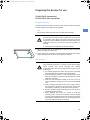
Preparing the devices for use
SR 300 IEM G2 transmitter/
SR 350 IEM G2 twin transmitter
Fitting the device feet
To ensure that the transmitter cannot slip on the surface on which it is placed,
four self-adhesive soft rubber feet are supplied.
Note:
Do not fit the rubber feet when rack mounting the transmitter.
CAUTION! Risk of staining of furniture surfaces!
Some furniture surfaces have been treated with varnish, polish
or synthetics which might cause stains when they come into
contact with other synthetics. Despite a thorough testing of the
synthetics used by us, we cannot rule out the possibility of
staining.
Do not place the transmitter on delicate surfaces.
Ensure that the base of the transmitter is clean and free from grease
before mounting the rubber feet.
Fix the rubber feet to the base of the transmitter by peeling off the safety
paper and fitting them as shown in the digram on the left.
Rack mounting
CAUTION! Risks when rack mounting the transmitter!
When installing the device in a closed or multi-rack assembly,
please consider that, during operation, the ambient
temperature within the rack may significantly rise above room
temperature.
The ambient temperature within the rack must not exceed
the temperature limit specified in the specifications.
When installing the device in a rack, take good care not to
affect the ventilation required for safe operation or provide
additional ventilation.
Make sure the mechanical loading of the rack is even to
avoid a hazardous condition such as a severely unbalanced
rack.
When connecting the device to the power supply, observe
the information indicated on the type plate. Avoid circuit
overloading. If necessary, provide overcurrent protection.
Ensure a reliable mains ground connection of the device by
taking appropriate measures.
When installing the device in a closed or multi-rack
assembly, please note that intrinsically harmless leakage
currents of the individual devices may accumulate, thereby
exceeding the allowable limit value. As a remedy, ground the
rack via an additional ground connection.
11
ew300_350_IEM_INT.book Seite 12 Freitag, 7. März 2008 8:55 08
Rack mounting the SR 350 IEM G2 The rack mount “ears” are already fitted to the twin transmitter on delivery.
twin transmitter To mount the twin transmitter into a 19’’ rack:
Slide the twin receiver into the 19’’ rack.
Secure the rack mount “ears” to the rack using four screws (not included).
Rack mounting the SR 300 IEM G2 For mounting one or two transmitters into a 19” rack, you require the GA 2
transmitter rack adapter. The GA 2 rack adapter consists of:
y 2 rack mount “ears” y 1 blanking plate y 1 jointing plate y 2 blanking plugs for closing off unused BNC holes
y 12 recessed head screws M 3x6
y 2 recessed head screws M 6x10
To mount two transmitters side by side into a rack:
Place the two transmitters side by side upside-down onto a flat surface.
Align the jointing plate over the holes in the bottom sides of the
transmitters.
Secure the jointing plate to the transmitters using eight of the supplied
recessed head screws (M 3x6).
Hook the two rack mount “ears” to the front panels of the transmitters.
Secure the rack mount “ears” to the transmitters using two of the
supplied recessed head screws (M 3x6) respectively.
Slide the transmitters into the 19” rack.
Secure the rack mount “ears” to the rack.
12
ew300_350_IEM_INT.book Seite 13 Freitag, 7. März 2008 8:55 08
When mounting only one transmitter into a rack, use the blanking plate instead of the second transmitter.
To mount only one transmitter into a rack:
Hook the two rack mount “ears” to the front panel of the transmitter.
Secure the rack mount “ears” to the transmitter using two of the supplied
recessed head screws (M 3x6) respectively.
Secure the blanking plate to one of the rack mount “ears” using two
of the supplied recessed head screws (M 6x10).
If you are not front mounting the BNC output connector, insert the two
blanking plugs into the holes of the blanking plate.
Slide the transmitter into the 19” rack.
Secure the rack mount “ears” to the rack.
Connecting the antenna
Connecting the antenna to the rear The supplied telescopic antenna can be mounted quickly and easily and are
of the transmitter suitable for all applications where – good transmission conditions provided –
a wireless transmission system is to be used without a large amount of
installation work.
Connect the telescopic antenna to the BNC socket at the rear of the
transmitter.
Pull the end cap to extend the telescopic antenna
.
Use a remote antenna (available as an accessory) when the transmitter
position is not the best antenna position for optimum transmission.
Antenna front mounting When mounting only one SR 300 IEM G2 transmitter or one SR 350 IEM G2
twin transmitter into a rack, you can use an antenna mount (optional
accessory) to mount the transmitter’s antenna connection to the front of the
rack.
Use the antenna mount matching the respective transmitter:
y For the SR 300 IEM G2 transmitter: AM 2 antenna mount
y For the SR 350 IEM G2 twin transmitter: GA 3030 AM antenna mount
13
ew300_350_IEM_INT.book Seite 14 Freitag, 7. März 2008 8:55 08
The antenna mounts consist of:
y 2 BNC extension cables (screw-in BNC socket
to BNC connector
)
y 2 washers
y 2 nuts
y 2 antenna holders (GA 3030 AM only)
y 4 screws (GA 3030 AM only)
To front mount the antenna of the SR 300 IEM G2 transmitter:
Screw the BNC socket of the BNC extension cables to the blanking plate
using the supplied washer and nut.
Connect the BNC connector
to the BNC socket on the transmitter.
Slide the transmitter into the 19’’ rack.
Secure the rack mount “ears” to the rack.
Connect the telescopic antenna
to the BNC socket
Pull the end cap to extend the telescopic antenna
.
.
To front mount the antennas of the SR 350 IEM G2 twin transmitter:
Unsecure the rack mount “ears” from the rack.
Guide the BNC cables through the holes in the rack mount “ears” as shown
in the diagram on the left.
Screw the antenna holders to the BNC sockets
washers and nuts.
using the supplied
Secure the antenna holders to the handles of the twin transmitter using
two of the supplied screws respectively.
14
ew300_350_IEM_INT.book Seite 15 Freitag, 7. März 2008 8:55 08
Connect the two BNC connectors
transmitter.
to the BNC sockets on the twin
Slide the twin transmitter into the 19’’ rack.
Resecure the rack mount “ears” to the rack .
Connect the telescopic antennas
to the BNC sockets
Pull the end caps to extend the telescopic antennas
.
.
Changing the transmission power (SR 350 IEM G2 only)
With the SR 350 IEM G2 twin transmitter, you can choose between two
different transmission powers.
ATTENTION! Danger of interference with other transmitters!
Depending on the selected transmission power and frequency,
you may have to apply for an approval from the respective
authority for a radio transmission licence, as you could interfere
with other transmitters. This approval will only be valid for the
approved transmission power. For detailed information, please
refer to the enclosed frequency data sheets and to the countryspecific frequency and transmission power overviews.
Apply for an approval, should country-specific regulations
on frequency and/or transmission power usage require this.
ATTENTION! Danger of damage to the device!
Due to the high transmission power (100 mW) in the switch
position “STANDARD”, the optional AC 2 transmitter combiner
must not be used as this can cause damage to the devices.
Use only the optional AC 3200 transmitter combiner (see
“Accessories and spare parts” on page 40).
Set the transmission power switch (RF POWER) to the desired position.
Transmission power will change as follows:
Switch position
Transmission power
LOW
15 mW
STANDARD
100 mW
15
ew300_350_IEM_INT.book Seite 16 Freitag, 7. März 2008 8:55 08
Connecting the transmitter to the mains
CAUTION! Damage due to electric current!
If you connect the transmitter to an unsuitable power supply,
this can cause damage to the device.
Use the supplied mains cable to connect the receiver to the
mains (100 to 240 V AC, 50 or 60 Hz).
Ensure a reliable mains ground connection of the receiver –
especially when you are using multi-outlet power strips or
extension cables.
Both transmitters have no mains switch.
To connect the transmitter to the mains:
Pass the cable through the cable grip .
Connect the supplied mains cable to the 3-pin IEC mains socket .
Plug the mains connector into the wall socket.
To disconnect the transmitter from the mains:
Pull out the mains connector from the wall socket.
Connecting the amplifier/mixing console
Connect the amplifier/mixing console to the XLR-3F sockets (left and
MONO) or (right).
Both balanced and unbalanced connection is possible (see “Connector
assignment” on page 39).
Note:
Any device that is only suitable for mono operation must be connected to
XLR-3F socket . In this case, set the transmitter to mono operation via
the menu.
Via the “Sensitiv” menu, adjust the transmitter’s input sensitivity (see
“Adjusting the sensitivity (transmitter only)” on page 30).
Connecting the headphones/ monitoring the audio signal
CAUTION! Danger of hearing damage!
Listening at high volume levels for long periods can lead to
permanent hearing defects.
Set the volume for the connected headphones to the
minimum before putting the headphones on.
To monitor the audio signal:
Neue Abbildung
Set the headphone volume control to the lowest volume by turning it
to the left as far as possible.
Connect headphones with a ¼” (6.3 mm) stereo jack plug to the
headphone output (PHONES) .
16
Gradually turn up the volume.
ew300_350_IEM_INT.book Seite 17 Freitag, 7. März 2008 8:55 08
Service interface/ connection to the NET 1 network system
The service interface (DATA A/B) is only required for servicing purposes.
In addition, the interface can also be used for connecting the
transmitter to the NET 1 network system. For detailed information,
please refer to the user manual of the NET 1.
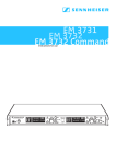
EK 300 IEM G2 receiver
Inserting and replacing the batteries
For powering the EK 300 IEM G2 receiver, two 1.5 V AA size batteries are
required.
Press the two release buttons and open the battery compartment
cover .
Insert the two batteries as shown in the diagram on the left. Please
observe correct polarity when inserting the batteries.
Close the battery compartment. The battery compartment cover locks
into place with an audible click.
Inserting and charging the accupack
The receiver can also be powered via the rechargeable Sennheiser BA 2015
accupack. Insert the accupack into the battery compartment as described
above.
The receiver has two charging contacts and a sensing contact on its short
sides. The accupack can be recharged while remaining in the receiver. Insert
the receiver into the L 2015 charger (see user manual of the L 2015 charger).
Note:
For accupack operation of the receiver, only use the BA 2015 accupack In
order to ensure optimum operational reliability. For charging the
accupack, only use the L 2015 charger. Both the accupack and the charger
are available as accessories.
The accupack is fitted with an integrated sensor which is – via a third
contact – monitored by the electronics of the receiver and the charger.
The sensor is necessary for the following control purposes:
y The taking into account of the different voltage characteristics of
primary cells (batteries) and accupacks. The battery status indications
on the displays, the transmission of transmitter battery status
information to the rack-mount receivers and the switch-off thresholds
at the end of the operating time are corrected correspondingly. Due to
the missing sensor, individual rechargeable battery cells will not be
identified as accupacks.
y The monitoring of the accupack temperature during charging in the L
2015 charger.
y The prevention of improper charging of inserted primary cells
(batteries). Due to the missing sensor, individual rechargeable battery
cells will also not be charged in the L 2015 charger.
17
ew300_350_IEM_INT.book Seite 18 Freitag, 7. März 2008 8:55 08
Connecting the headphones
CAUTION! Danger of hearing damage!
Listening at high volume levels for long periods can lead to
permanent hearing defects.
Set the volume for the connected headphones to the
minimum before putting the headphones on.
For monitoring purposes, connect the supplied earphones or any
Sennheiser stereo headphones with 3.5 mm stereo jack plug to the
headphone output (PHONES) .
First, set the volume control to the lowest volume by turning it to the
left as far as possible. Then gradually turn up the volume.
Using the components
Switching the components on/off
Switching the transmitter on/off
Press the ON button to switch the transmitter on.
To switch the transmitter off, press the ON button until “OFF” appears on
the display.
Note:
The transmitter can only be switched off when the standard display is
shown on the display panel. Within the operating menu, the ON button
serves as the ESC (cancel) key, i.e. you cancel your entry and return to the
standard display.
After switch-off, the transmitter is in standby mode. To disconnect the
transmitter from the mains, pull out the mains connector from the wall
socket!
Switching the receiver on/off
To switch the receiver on, turn the volume control clockwise until it
clicks. The red LED lights up.
To switch the receiver off, turn the volume control counterclockwise
until it clicks. The red LED goes off.
Note:
y The receiver has a short switch-on delay.
y Remove the batteries or the accupack when the receiver will not be used
for extended periods of time.
18
ew300_350_IEM_INT.book Seite 19 Freitag, 7. März 2008 8:55 08
Adjusting the volume
CAUTION! Danger of hearing damage!
Listening at high volume levels for long periods can lead to
permanent hearing defects.
Set the volume for the connected headphones to the
minimum before putting the headphones on.
You can adjust the volume at the headphone output on both the transmitter
and the receiver.
Use the volume control or to adjust the volume of the connected
headphones.
Adjusting the balance
During stereo operation – and provided that the standard display is shown
on the display panel – the / rocker button serves to adjust the balance
between the left and right stereo signal.
During FOCUS operation, the / rocker button serves to adjust the
relative levels of the two separate channels in the mixed mono signal (see
“Stereo/FOCUS selection (receiver only)” on page 30).
Activating/deactivating the lock mode
Transmitter and receiver have a lock mode that can be activated or
deactivated via the operating menu (see “Activating/deactivating the lock
mode” on page 33). The lock mode prevents that
SR 300 IEM G2/SR 350 IEM G2
y the transmitter is accidentally programmed or switched off during
operation,
y the balance setting is accidentally changed via the receiver’s / rocker
button.
EK 300 IEM G2
Attaching the receiver to clothing
The receiver is attached to clothing (e.g. belt, waistband) with the supplied
belt clip.
19
ew300_350_IEM_INT.book Seite 20 Freitag, 7. März 2008 8:55 08
The operating menu
To ensure intuitive operation of both transmitter and receiver, the operating
menus have been largely standardized. As a result, adjustments to the
settings can be made quickly and “without looking” – even in stressful
situations, for example on stage or during a live show or presentation.
The buttons
Buttons
ON
(transmitter
only)
SET
/
ESC
(receiver only)
20
Mode
To ...
Standard display
switch the transmitter on and off
Operating menu
cancel the entry and return to the
standard display
Setting mode
cancel the entry and return to the
standard display
Standard display
get into the operating menu
Operating menu
get into the setting mode of the
selected menu
Setting mode
store the settings and return to the
previous menu level
Standard display
without function (transmitter)
adjust the balance (receiver)
Operating menu
change to the previous menu ()
or change to the next menu ()
Setting mode
adjust the setting of the selected
menu:
option (/)
Standard display
without function
Operating menu
cancel the entry and return to the
standard display
Setting mode
cancel the entry and return to the
standard display
ew300_350_IEM_INT.book Seite 21 Freitag, 7. März 2008 8:55 08
Overview of menus
Transmitter
Receiver
Display
Function of the menu
Display
Function of the menu
Bank
Switching between channel banks
BANK
Switching between channel banks
Channel
Switching between the channels in
a channel bank
CHAN
Switching between the channels in
a channel bank
Tune
Setting a transmission frequency for the
channel bank “U” (user bank)
TUNE
Setting a receiving frequency for the
channel bank “U” (user bank)
⎯
⎯
SCAN
Scanning a channel bank for free
channels
⎯
⎯
SQELCH
Adjusting the squelch threshold
⎯
⎯
ST-FOC
Stereo/FOCUS selection
⎯
⎯
LTD
Limiting the volume at the
headphone output
⎯
⎯
Hi-BST
Activating/deactivating
the frequency boost
Sensitiv
Adjusting the sensitivity
⎯
⎯
Display
Selecting the standard display
DISPLY
Selecting the standard display
Name
Entering a name
NAME
Entering a name
Reset
Loading the factory-preset
default settings
RESET
Loading the factory-preset
default settings
⎯
⎯
PILOT
Activating/deactivating
the pilot tone evaluation
LCD Contr
Adjusting the contrast of the
graphic display
⎯
⎯
Mode
Stereo/mono selection
⎯
⎯
Lock
Activating/deactivating the lock mode
LOCK
Activating/deactivating the lock mode
Exit
Exiting the operating menu and
returning to the standard display
EXIT
Exiting the operating menu and
returning to the standard display
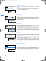
Working with the operating menu
By way of example of the “Tune” menu, this section describes how to use the
operating menu.
After switching the unit on, the standard display is shown on the display
panel.
SR 300 IEM G2/SR 350 IEM G2
EK 300 IEM G2
21
ew300_350_IEM_INT.book Seite 22 Freitag, 7. März 2008 8:55 08
Getting into the operating menu
Press the SET button to get from the standard display into the operating
menu.
The last menu selected flashes on the display. With the transmitter, the
current setting is additionally displayed.
Selecting a menu
Press the / rocker button to select a menu.
Press the SET button to get into the setting mode of the selected menu.
With the receiver, the current setting that can be adjusted flashes on the
display. With the transmitter, the name of the menu and the current
setting are displayed.
Adjusting a setting
Press the / rocker button to adjust the setting.
By briefly pressing the / rocker button, the display jumps either
forwards or backwards to the next setting. In the “Channel”, “Tune” and
“Name” menu, the / rocker button features a “fast search” function.
If you hold down a button, the display cycles continuously. The “fast
search” function allows you to get fast and easily to your desired setting.
With the receiver, the new setting flashes on the display until it is stored.
Storing a setting
Press the SET button to store the setting. “Stored” appears on the display,
indicating that the setting has been stored. The display then returns to
the top menu level.
With most menus, new settings become effective immediately without
having to be stored. An exception are the “Bank”, “Channel”, “Tune” and
“Reset” menus of the transmitter and the “RESET” menu of the receiver.
With these menus, new settings only become effective after they have
been stored (“Stored” appears on the display, indicating that the setting
has been stored).
Exiting the operating menu
Select the “Exit” menu to exit the operating menu and to return to the
standard display.
When you have entered the operating menu, the transmitter’s ON button
serves as the ESC (cancel) key, i.e. by briefly pressing this button, you
cancel your entry and return to the standard display. The receiver has a
separate ESC button with which you can cancel your entry.
22
ew300_350_IEM_INT.book Seite 23 Freitag, 7. März 2008 8:55 08
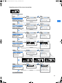
Operating menu of the stereo transmitter
SET
Exit
Menu
Exit
Bank
Channel
SET
1
01
Bank
1.01
B.CH
786.300 MHz
Current channel bank
Changing the channel bank
Bank
3.01
B.CH
790.250 MHz
/ : 1...8, U (User Bank)
SET: Stores the setting
Stored
Menu
Bank
3
Channel 01
Tune
786.400MHz
SET
Channel
3.01 790.250 MHz
B.CH
Current channel and
corresponding frequency
Changing the channel
Channel
3.08 807.900 MHz
B.CH
/ : Channel
01...12
SET: Stores the setting
Stored
Menu
Channel 08
Tune
807.900MHz
Sensitiv –24 dB
SET
Tune
U.01
B.CH
786.300 MHz
Current frequency on the
selected channel
Setting the frequency for
channel bank "U"
Tune
U.01
B.CH
797.075 MHz
/ : Transmission frequency
in steps of 25 kHz
SET: Stores the setting
Stored
Menu
Tune
Sensitiv
Display
SET
797.075MHz
–24 dB
Frequency
Sensitiv
– 24 dB
Current sensitivity setting
Sensitiv
–8 dB
/ : 0...–24 dB,
Sensitivity in steps of 8 dB
Setting the sensitivity
SET: Stores the setting
Stored
Menu
Sensitiv
Display
Name
SET
–8 dB
Frequency
VOCAL
Display
Frequency
Display
Name
Current standard display
/ : Frequency,
Bank/Channel, Name
Switching between the
standard displays
SET: Stores the setting
Stored
Frequency
Menu
Display
Name
Reset
SET
Name
VOCAL
Name
Bank/Channel
Name
OCAL
Current transmitter name
Assigning the transmitter a
name
Stored
Name
G CAL
/ : Name (10 characters)
Letters w/o pronounciation
marks, numbers from 0...9,
special characters, spaces
SET: 9 x next character, then
store
Reset
23
ew300_350_IEM_INT.book Seite 24 Freitag, 7. März 2008 8:55 08
Name
GUITAR
Menu
Name
GUITAR
Reset
LCD Contr IIIIII.....
SET
Reset
Reset? No
Security check
Loading the factory-preset
default settings
Reset
Reset? Yes
/ : No, Yes
"reset"= Yes:
SET: Transmitter loads factorypreset default settings,
transmitter is restarted,
standard display appears
"reset"= No:
SET: Reset is cancelled
Menu
Reset
LCD Contr IIIIII.....
Mode
Stereo
SET
LCD Contrast
IIIIII..........
Current contrast setting
Adjusting the contrast of the
graphic display
LCD Contrast
IIIIIIIIII......
/ :
16 steps
SET: Stores the setting
STORED
Menu
LCD Contr IIIIIIIIII......
Mode
Stereo
Lock
Off
SET
Mode
Stereo
Current setting
Switching between stereo
and mono operation
Mode
Mono
/ : Stereo, Mono
SET: Stores the setting
STORED
Menu
Mode
Lock
Exit
SET
Mono
Off
Lock
Off
Lock
On
Lock mode activated or
deactivated
Activating the lock mode
STORED
Menu
Lock
Exit
Bank
SET
On
3
Exiting the operating menu
Bank
24
3
/ : On, Off
Lock mode = On:
SET: Stores the setting,
returns to standard display
Lock mode = Off:
SET: Stores the setting
ew300_350_IEM_INT.book Seite 25 Freitag, 7. März 2008 8:55 08
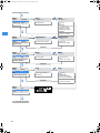
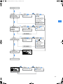
Operating menu of the stereo receiver
EXIT
SET
BANK
SET
Changing the channel
bank
BANK 1
BANK U
Current channel bank
/ : 1...8, U (User
Bank)
SET: Stores the setting
STORED
CHAN
SET
Changing the channel
1.01
1.12
B.CH
Current channel or
frequency
/ : Channel
B.CH
01...12
SET: Stores the setting
STORED
TUNE
SET
790.025 MHz
Current frequency on
the selected channel
Setting the frequency
for channel bank "U"
791.125 MHz
/ : Receiving
frequency in steps of
25 kHz
SET: Stores the setting
STORED
SCAN
SET
Scanning the selected
channel bank for free
channels
U.
START
09 CH FREE
STORED
Setting the squelch
threshold
CLEAR
/ : CLEAR, START
SET
SQELCH
U.
SET
SQ LO
Current squelch
threshold
Start scan = START
SET: Scans the selected
channel bank for free
channels
Delete result = CLEAR
SET: Releases locked
channels
SQ HI
/ :
LO, MID, HI
SET: Stores the setting
STORED
ST--FOC
25
ew300_350_IEM_INT.book Seite 26 Freitag, 7. März 2008 8:55 08
SQELCH
ST--FOC
SET
Switching between
stereo and FOCUS
operation
STEREO
Current setting
FOCUS
/ :
Stereo, Focus
SET: Stores the setting
STORED
SET
LTD
LTD.OFF
OFF
Limiter activated or
deactivated
Limiting the volume at
the headphone output
LTD. ON
/ : OFF, ON
SET: Stores the setting
STORED
HI--BST
SET
HB.OFF
OFF
Frequency boost
activated or deactivated
Boosting the AF
frequency response
HB. ON
/ : OFF, ON
SET: Stores the setting
STORED
DISPLY
SET
CHAN
Current standard display
Switching between the
standard displays
NAME
/ :
FREQ, NAME,
CHAN
SET: Stores the setting
STORED
NAME
Assigning the receiver
a name
SET
VOCAL
Current receiver name
GUCAL
/ :
Enter a name (6
characters) Letters w/o
pronounciation marks,
numbers from 0...9, special
characters, spaces
STORED
RESET
26
SET: 5 x next character,
then store
ew300_350_IEM_INT.book Seite 27 Freitag, 7. März 2008 8:55 08
NAME
SET
RESET
RST. NO
Security check
Loading the factorypreset default settings
RST. OK
/ : OK, NO
"reset" = OK:
SET: Receiver loads factorypreset default settings (only
pilot tone setting is kept),
receiver is restarted,
standard display appears
"reset" = NO
SET: Reset is cancelled
PILOT
SET
PLT. ON
PLT. OFF
/ : ON, OFF
Activating/deactivating
the pilot tone
transmission
Pilot tone transmission
activated or deactivated
SET: Stores the setting
STORED
LOCK
SET
LOC.OFF
OFF
Lock mode activated or
deactivated
Activating the lock mode
STORED
EXIT
LOC. ON
/ : ON, OFF
Lock mode = ON:
SET: Stores the setting,
("STORED") returns to
standard display
Lock mode = OFF:
SET: Stores the setting
SET
Exiting the operation
BANK
BAL.L 1
Current balance setting
BAL.R 15
/ : BAL.L 1...15,
BAL.--0--, BAL.R 1...15
Adjusting the balance
27
ew300_350_IEM_INT.book Seite 28 Freitag, 7. März 2008 8:55 08
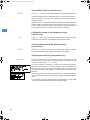
Adjustment tips for the operating menu
Switching between channel banks
BANK
Bank
Via the “Bank” menu, you can switch between the nine channel banks of the
ew 300 IEM G2 transmitter and receiver. The channel banks “1” to “8” have
up to 12 switchable channels that are factory-preset to a transmission/
receiving frequency (see “The channel bank system” on page 5). The channel
bank “U” (user bank) also has up to 12 switchable channels to store your
selection out of 1,440 transmission/receiving frequencies that are freely
selectable within the preset frequency range.
When switching from one channel bank to another, the channel with the
lowest channel number is automatically displayed. If, during the last scan of
this channel bank, an interfering frequency was detected on the channel with
the lowest channel number, the receiver display panel automatically displays
the next free channel (see below).
Switching between the channels in a channel bank
CHAN
Channel
Via the “Channel” menu, you can switch between the channels in a channel
bank.
Always set the transmitter and the receiver of a transmission link to the same
channel. After scanning a channel bank (see “Scanning the channel banks for
free channels (receiver only)” on page 28), only the free channels are
displayed. Set the transmitter to one of the free channels.
Selecting the frequencies to be stored
in the channel bank “U”
TUNE
Tune
Via the “Tune” menu, you can select the frequencies to be stored in the
channel bank “U” (user bank).
When you have selected one of the channel banks “1” to “8” and then select
the “Tune” menu, the transmitter or receiver automatically switches to
channel 01 of the channel bank “U”. In this case, “U.01” briefly appears on
the display.
Use the / rocker button to select the desired transmission or receiving
frequency. Transmission and receiving frequencies are tunable in 25-kHz
steps within a switching bandwidth of 36 MHz max. For intermodulationfree frequencies, please refer to the enclosed frequency table.
Scanning the channel banks for free channels
(receiver only)
SCAN
Before putting one or several transmission links into operation, you should
scan the selected channel bank for free channels.
Starting the scan and storing the scan result
Before starting the scan, switch all transmitters of your system off, since
channels used by switched-on transmitters will not be displayed as “free
channels”.
Select the “SCAN” menu.
28
ew300_350_IEM_INT.book Seite 29 Freitag, 7. März 2008 8:55 08
Select “START” and confirm your selection by pressing the SET button.
After the scan is completed, the number of free channels is displayed.
Pressing the SET button once more will store the scan result and lock all
channels that are used or subject to interference.
Releasing locked channels
Select the “SCAN” menu.
Select “CLEAR” and confirm your selection by pressing the SET button. All
channels in this channel bank can now be selected again.
Multi-channel operation
For multi-channel operation, only use the free channels in a channel bank.
Before putting the transmission links into operation, we recommend
performing an auto scan.
Select a channel bank on a receiver.
Scan this channel bank for free channels. If not enough free channels are
available in the selected channel bank, repeat the scan with another
channel bank.
Apply the scan result to all other transmitters and receivers.
Note:
If you have the SR 350 IEM G2 twin transmitter connected to the NET 1
network system, follow the instructions of the user manual of the NET 1.
Adjusting the squelch threshold (receiver only)
SQELCH
The receiver is equipped with a squelch that can be adjusted via the “SQELCH”
menu. The squelch eliminates annoying noise when the transmitter is
switched off. It also suppresses sudden noise when there is no longer
sufficient transmitter power received by the receiver.
Note:
Before adjusting the squelch threshold to a different setting, use the
volume control to set the volume for the connected headphones to the
minimum.
There are three possible squelch settings:
y LO
= low
y MID
= middle
y HI
= high
Selecting the setting “LO” reduces the squelch threshold, selecting the
setting “HI” increases the squelch threshold. Adjust the squelch threshold –
with the transmitter switched off – to the lowest possible setting that
suppresses hissing noise.
Notes:
y If the squelch threshold is adjusted too high, the transmission range will
be reduced. Therefore, always adjust the squelch threshold to the
lowest possible setting.
y When in the setting mode of the “SQELCH” menu, pressing the
button for more than three seconds will switch the squelch off.
“SQ.OFF” appears on the display. If no RF signal is being received,
hissing noise will occur. This setting is for test purposes only.
29
ew300_350_IEM_INT.book Seite 30 Freitag, 7. März 2008 8:55 08
Stereo/FOCUS selection (receiver only)
ST-FOC
Via the “ST-FOC” menu, you can switch between stereo and FOCUS operation.
In both operating modes, the transmitter has to be set to stereo operation.
When the receiver is set to stereo operation, the left-right signals are
available as usual.
When the receiver is set to FOCUS operation, the left-right signals are mixed
and are available as a mono signal in both headphone channels. Use the /
rocker button to adjust the relative levels of the two separate channels in
the mixed mono signal (see “Adjusting the balance” on page 19).
Limiting the volume at the headphone output
(receiver only)
LTD
Via the “LTD” menu, you can switch the limiter on and off. With the limiter
switched on, the volume at the headphone output will be reduced.
Activating/deactivating the frequency boost
(receiver only)
HI-BST
Via the “HI-BST” menu, you can boost the AF frequency response at 10 kHz.
As a result, headphones with magnetic transducers sound better.
Adjusting the sensitivity (transmitter only)
Sensitiv
To match the transmitter to the output level of the connected unit (e.g.
mixing console), you can adjust the input sensitivity in four steps of 8 dB
(from 0 to –24 dB) via the “Sensitiv” menu.
The input sensitivity is adjusted too high when close talking distances,
speakers with loud voices or loud music passages cause overmodulation in
the transmission link. In this case, the transmitter’s “PEAK” warning will light
up and the receiver’s level display for audio signal “AF” will show full
deflection.
If, on the other hand, the sensitivity is adjusted too low, the transmission link
will be undermodulated, which would result in a signal with high background
noise.
The sensitivity is correctly adjusted when the level display for audio signal
“AF” shows full deflection only during the loudest passages.
30
ew300_350_IEM_INT.book Seite 31 Freitag, 7. März 2008 8:55 08
Selecting the standard display
DISPLY
Display
Via the “Display” menu, you can select the standard display.
SR 300 IEM G2 transmitter/SR 350 IEM G2 twin transmitter
Selectable standard display
Contents of standard display
“Frequency”
(display of the frequency)
“Bank/Channel”
(display of the channel bank
and channel number)
“Name”
(display of the freely selectable
name)
EK 300 IEM receiver
Selectable standard display
Contents of standard display
“FREQ”
“NAME”
“CHAN”
31
ew300_350_IEM_INT.book Seite 32 Freitag, 7. März 2008 8:55 08
Entering names
NAME
Name
Via the “Name” menu, you can enter a freely selectable name for the
transmitter and the receiver. You can, for example, enter the name of the
performer for whom the adjustments have been made.
The name can be displayed on the standard display and can consist of up to
ten characters (transmitter) and up to six characters (receiver) such as:
y letters (without pronounciation marks),
y numbers from 0 to 9,
y special characters e.g. () - . _ and spaces.
To enter a name, proceed as follows:
Press the SET button to get into the setting mode of the “Name” menu.
The first segment starts flashing on the display.
With the / rocker button you can now select a character. By briefly
pressing a button, the display jumps either forwards or backwards to the
next character. If you hold down a button, the display starts cycling
continuously.
Press the SET button to change to the next segment and select the next
character.
Have you entered the name completely? Press the SET button to store
your setting and to return to the previous menu level.
Loading the factory-preset default settings
RESET
Reset
Via the “Reset” menu, you can load the factory-preset default settings. With
the receiver, however, the selected setting for the pilot tone remains
unchanged. After the reset, the device is restarted and the standard display
is shown on the display panel.
Activating/deactivating the pilot tone evaluation
(receiver only)
PILOT
Pilot
Via the “Pilot” menu, you can activate or deactivate the pilot tone evaluation
of the receiver.
The pilot tone is used to
y code the transmitter’s stereo signal,
y support the squelch function (Squelch).
During stereo operation, the transmitter adds the pilot tone to the
transmitted stereo signal and the receiver detects and evaluates the pilot
tone. When the transmitter is set to mono operation, deactivate the pilot
tone evaluation on the receiver.
You can combine units of first and second generation ew 300 IEM systems
without any problems.
Adjusting the contrast of the graphic display (transmitter
only)
LCD-Contr
32
Via the “LCD Contr” menu, you can adjust the contrast of the graphic display
in 16 steps.
ew300_350_IEM_INT.book Seite 33 Freitag, 7. März 2008 8:55 08
Stereo/mono selection (transmitter only)
Mode
Via the “Mode” menu, you can switch the transmitter between mono and
stereo operation.
Note:
Connect any unit that only delivers a mono signal to the transmitter’s left
XLR-3F socket and set the transmitter to mono operation. The receiver
automatically “identifies” the transmitted audio signal and does not need
to be set to mono operation. However, you have to deactivate the pilot
tone evaluation on the receiver.
Activating/deactivating the lock mode
LOCK
Lock
Via the “Lock” menu, you can activate or deactivate the lock mode.
The lock mode icon on the display indicates that the lock mode is activated.
To deactivate the lock mode, first press the SET button. Then press the /
rocker button to select “LOC.OFF”. If you confirm your selection by pressing
the SET button, the buttons can be operated as usual.
SR 300 IEM G2/SR 350 IEM G2
EK 300 IEM G2
Exiting the operating menu
EXIT
Exit
Via the “Exit” menu, you can exit the operating menu and return to the
standard display.
33
ew300_350_IEM_INT.book Seite 34 Freitag, 7. März 2008 8:55 08
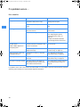
If a problem occurs ...
Error checklist
Problem
Possible cause
Possible solution
No operation indication
Batteries are flat or
accupack is flat (receiver only)
Replace the batteries or
recharge the accupack
No mains connection (transmitter
only)
Check the connections of the mains
unit
Transmitter and receiver are not on
the same channel
Set transmitter and receiver to the
same channel
Transmission range is exceeded
Check the squelch threshold setting
(see “Adjusting the squelch
threshold (receiver only)” on
page 29)
No RF signal
or reduce the distance between
transmitting antenna and receiver
Transmitter is set to mono operation
and the pilot tone evaluation of the
receiver is activated
Deactivate the pilot tone evaluation
on the receiver
Receiver’s squelch threshold is
adjusted too high
See “Adjusting the squelch threshold
(receiver only)” on page 29)
Audio signal has a high level
of background noise
Transmitter sensitivity is adjusted
too low
See “Adjusting the sensitivity
(transmitter only)” on page 30
Audio signal is distorted
Transmitter sensitivity is adjusted
too high
See “Adjusting the sensitivity
(transmitter only)” on page 30
No access to a certain channel
During scanning, an RF signal has
been detected on this channel and
the channel has been locked
See “Scanning the channel banks for
free channels (receiver only)” on
page 28
RF signal available,
no audio signal,
“MUTE” display appears on
the display panel
If a problem occurs that is not listed in the above table or if the problem cannot be solved with the proposed
solutions, please contact your local Sennheiser agent for assistance.
34
ew300_350_IEM_INT.book Seite 35 Freitag, 7. März 2008 8:55 08
Recommendations and tips
... for the EK 300 IEM G2 receiver
y The antenna should hang freely and be at least 1 cm away from the body.
The antenna must not be in direct contact with the skin.
... for optimum reception
y Transmission range depends to a large extent on location and can vary
from about 10 m to about 150 m. There should be a “free line of sight”
between transmitting and receiving antennas.
y If, with the SR 300 IEM G2 transmitter or the SR 350 IEM G2 twin receiver,
transmission conditions are unfavourable, you should use a remote
antenna which is connected via antenna cable.
y To avoid overmodulating the receiver, observe a minimum distance of 5 m
between transmitting and receiving antennas.
y Observe a minimum distance of 50 cm between the transmitting antennas
and metal objects (such as cross members or reinforced-concrete walls).
... for multi-channel operation
y For multi-channel operation, you can only use the channels in a channel
bank. Each of the channel banks “1” to “8” accommodates up to 12
factory-preset frequencies which are intermodulation-free. For alternative
frequency combinations, please refer to the enclosed frequency table. The
freely selectable frequencies can be selected via the “Tune” menu and can
be stored in the channel bank “U”.
y When using several transmitters simultaneously, interference can be
avoided by maintaining a minimum distance of 20 cm between two
transmitters. For multi-channel applications, use the appropriate
transmitter combiners (see “Accessories and spare parts” on page 40):
y SR 300 IEM G2 stereo transmitter:
AC 2 transmitter combiner
y SR 350 IEM G2 twin transmitter:
AC 2 transmitter combiner (only when the transmission power is set to
“LOW”) or AC 3200 transmitter combiner
Care and maintenance
Use a slightly damp cloth to clean the units from time to time.
Note:
Do not use any cleansing agents or solvents.
35
ew300_350_IEM_INT.book Seite 36 Freitag, 7. März 2008 8:55 08
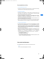
Additional information
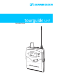
HDX noise reduction
RF link
Inherent noise
of the RF link
Transmitter
Receiver
Progress you can hear:
The evolution wireless G2 series is equipped with HDX, the Sennheiser noise
reduction system that reduces RF interference. It increases the signal-tonoise ratio in wireless audio transmission to more than 110 dB.
HDX is a wideband compander system which compresses the audio signal in
the transmitter in a 2:1 ratio (related to dB) to lift it above the inherent noise
floor of the RF link. In the receiver the signal is expanded in an identical and
opposite way in a 1:2 ratio to restore the original signal, at the same time
reducing the RF noise to below the noise floor of the receiver.
HDX has been specially developed for high quality radiomicrophone systems.
Note:
Only transmitters and receivers that are equipped with HDX can work
correctly with each other. If non HDX equipment was mixed with HDX, the
dynamic range would be drastically reduced and the transmission would
sound blunt and flat. HDX is permanently active and cannot be switched
off.
Wireless transmission systems
With the ew 300 IEM G2 system, Sennheiser puts an end to cable tangles and
enables complete freedom of movement. The systems operate exclusively in
the UHF band. UHF transmission is extremely reliable and is far less prone to
interference than the overcrowded VHF band – harmonics from mains units,
fluorescent tubes, refrigerators, computers, etc. are virtually eliminated. Also
indoor propagation of UHF radio waves is better than VHF so that the RF
power can be kept low – this is also an advantage when using multi-channel
systems. Finally, UHF frequency ranges are being approved all over the world
for radiomicrophone usage – in some countries licence-free.
Correct adjustment of transmitter sensitivity is vital. Too high and you get
overmodulation and distortion, too low and you get undermodulation and a
noisy signal. Please set the sensitivity correctly for the microphone/usage
and check it before every performance to ensure best operation.
36
ew300_350_IEM_INT.book Seite 37 Freitag, 7. März 2008 8:55 08
Squelch
Pilot tone squelch
The transmitter adds a 19-kHz pilot tone to the audio signal. The receiver
checks incoming audio signals to see if the pilot tone is present. In the
absence of the 19-kHz signal, the receiver’s audio output will remain muted,
even if a strong RF signal is present.
This prevents strong interfering signals from causing hissing noise in the
receiver when the transmitter is switched off.
Field strength-dependent squelch
Depending on the strength of the received RF signal, the receiver’s audio
output is opened or muted. Via the “SQELCH” menu of the receiver, the
squelch threshold can be adjusted in three steps (LO, MID, HI).
37
ew300_350_IEM_INT.book Seite 38 Freitag, 7. März 2008 8:55 08
Specifications
System
RF characteristics
Modulation
Frequency ranges
Transmission/receiving frequencies
wideband FM stereo, MPX pilot tone
518–554, 572–608, 626–662, 740–776, 786–822,
830–866 MHz
8 channel banks with up to 12 factory-preset channels each
Switching bandwidth
Nominal/peak deviation
Frequency stability
1 channel bank with up to 12 freely selectable channels
(1,440 frequencies, tunable in steps of 25 kHz)
36 MHz
± 24 kHz/± 48 kHz
≤ ± 15 ppm
AF characteristics
Noise reduction system
AF frequency response
MPX pilot tone (frequency/deviation)
S/N ratio (at 1 mV and peak deviation)
THD (at nominal deviation and 1 kHz)
Sennheiser HDX
40–15,000 Hz
19 KHz/±4 kHz
≥ 91 dB(A)
≤ 0,9 %
General data
Temperature range
Dimensions of carrying case [mm]
Weight of carrying case
–10 °C to +55 °C (with SR 350 IEM G2: –10 °C to +45 °C)
380 x 370 x 70
approx. 3 kg
IE 4 earphones
Frequency response
Max. SPL
Impedance
40–20,000 Hz
106 dB (1 kHz, 1 mW)
16 Ω
EK 300 IEM G2 receiver
RF characteristics
Receiver principle
Sensitivity (with HDX, peak deviation)
Adjacent channel rejection
Intermodulation attenuation
Blocking
Squelch
Pilot tone squelch (MPX pilot tone)
non diversity
< 2.5 μV at 52 dBArms S/N
≥ 70 dB
≥ 70 dB
≥ 80 dB
4 steps:
OFF
LO: 5 dBμV
MID: 15 dBμV
HI: 25 dBμV
can be switched off
AF characteristics
Headphone output
3.5 mm jack socket
AF output voltage (peak deviation, 1 kHzAF) PHONES 2 x ≥ 100 mW at 32 Ω
Overall device
Power supply
Nominal voltage
Max. power consumption at nominal voltage
Power consumption with switched-off receiver
Operating time (with batteries)
Operating time (with BA 2015 accupack)
Dimensions [mm]
Weight (incl. batteries)
38
2 AA size batteries, 1.5 V
2.4 V
approx. 190 mA (2 x 30 mW)
≤ 250 μA
6–10 hrs (depending on volume level)
6–10 hrs (depending on volume level)
82 x 64 x 24
approx. 170 g
ew300_350_IEM_INT.book Seite 39 Freitag, 7. März 2008 8:55 08
SR 300 IEM G2 transmitter/SR 350 IEM G2 twin transmitter
RF characteristics
RF output power at 50 Ω
SR 300 IEM G2
20 mW
SR 350 IEM G2
100 mW, switchable to 15 mW
ERP
Antenna output
depending on
antenna type used
BNC socket, 50 Ω
depending on
antenna type used
BNC socket, 50 Ω
AF characteristics
Headphone output
Output power at headphone output
AF input
Max. input voltage (peak deviation, 1 kHz)
Input impedance
¼’’ (6.3 mm) stereo jack socket
≥ 100 mW an 32 Ω (2x)
2 x XLR-3 socket, electronically balanced
+20 dBu
10 kΩ
Overall device
Power supply
Nominal voltage
Power consumption at nominal voltage
Dimensions [mm]
Weight
SR 300 IEM G2
SR 350 IEM G2
10,5–16 V DC
12 V DC
approx. 300 mA
212 x 145 x 38
approx. 1100 g
100–240 V AC/50–60 Hz
approx. 400 mA
436 x 215 x 43
approx. 3960 g
Type approvals
Area
Conformity
SR 300 IEM G2
SR 350 IEM G2
USA:
FCC-Part 74.861
FCC ID: DMOF2EUVL
RSS-123
IC: 2099A - G2SREK
FCC-Part 74.861
FCC ID: DMOSR350
RSS-123
IC: 2099A-SR350
Canada:
EU:
0682
complies with the requirements for Radio and
Telecommunications Terminal Equipment (R&TTE):
y EN 300422-1/-2, class II
y EN 301489-1/-9
complies with the requirements for safety (LVD):
y EN 60065
0682
complies with the requirements for Radio and
Telecommunications Terminal Equipment (R&TTE):
y EN 300422-1/-2, class II
y EN 300454-1/-2
y EN 301489-1/-9
complies with the requirements for safety (LVD):
y EN 60065
Connector assignment
SR 300/350 IEM G2:
SR 300/350 IEM G2:
SR 300:
¼’’ (6.3 mm) stereo jack plug
for headphone output
XLR-3M connector
DC connector for power 3.5 mm stereo jack plug
supply
for headphone output
+
2
EK 300 IEM G2:
1
3
39
ew300_350_IEM_INT.book Seite 40 Freitag, 7. März 2008 8:55 08
Accessories and spare parts
Cat. No. Accessory/spare part
009823 GA 2:
19’’ rack adapter
009912 AM 2 (for SR 300 IEM G2):
Antenna mount for mounting antennas to the front of the GA 2 rack adapter
004645 A 1031-U:
UHF antenna, passive, omni-directional, can be mounted onto a stand
003658 A 2003 UHF:
UHF antenna, passive, directional, can be mounted onto a stand
004368 GA 3030-AM (for SR 350 IEM G2):
Antenna mount
002324 GZL 1019-A1:
Antenna cable with BNC connectors, length: 1 m
002325 GZL 1019-A5:
Antenna cable with BNC connectors, length: 5 m
009822 AC 2:
Transmitter combiner, for combining the RF signals of up to four transmitters
onto a single antenna and for powering up to four transmitters
502048 AC 3200:
Transmitter combiner, for combining the RF signals of up to eight transmitters onto a single antenna and for powering up to eight transmitters
004863 NT 3:
Plug-in mains unit for AC2
500432 IE 4:
1 pair of earphones with medium ear sleeves
512814 IES 4–L:
Ear sleeves, large (10 pieces)
512815 IES 4–M:
Ear sleeves, medium (10 pieces)
512816 IES 4–S:
Ear sleeves, small (10 pieces)
009950 BA 2015:
Accupack
009828 L 2015:
Charger for BA 2015 accupack
009826 CC 2:
Carrying case for ew 300 IEM G2 system
40
ew300_350_IEM_INT.book Seite 41 Freitag, 7. März 2008 8:55 08
Manufacturer Declarations
Warranty
The original Sennheiser product you have purchased is covered by a warranty
of 24 months. The warranty period begins on the date of purchase of brand
new, unused products by the first end user. Please retain your sales receipt
(or your warranty certificate) as proof of purchase. Unless you submit proof
of purchase, which will be verified by your local Sennheiser service partner,
you will be obliged to pay for any repairs that are carried out. Proof of
purchase must state the date of purchase and name of the product.
We shall satisfy our warranty obligations by remedying any material or
manufacturing faults free of charge at our discretion either by repair or by
exchanging individual parts or the entire appliance. Any defective parts
removed from a product during the course of a warranty claim shall become
the property of Sennheiser electronic GmbH & Co. KG.
The following cases are not covered by the above warranty:
y minor faults or deviations in the quality of a product which do not affect
the product's value or fitness for its intended purpose
y any accessories supplied with the product
y rechargeable and disposable batteries (these products have a shorter
service life, the length of which also depends on the frequency of use)
y faults resulting from improper use (e.g. operating errors, mechanical
damage, incorrect operating voltage)
Proper use for the purposes of this warranty is defined as use of the
product under the conditions stated in the instructions for use.
y faults due to wear and tear
y any modification of Sennheiser products effected by you or a third party,
unless Sennheiser has given its prior written consent to the nature and
extent of the modification
y faults due to force majeure
y faults of which the purchaser was already aware at the time of purchase
All warranty claims become void if the product is tampered with by
unauthorised persons or repair shops.
Warranty claims can be enforced in any country throughout the world in
which the statutory rights of the country concerned are not in conflict with
our warranty regulations. No other warranty claims or claims over and above
the rights stated in these terms and conditions will be accepted.
Consumers may be entitled to statutory rights in their own countries which
are not restricted by these warranty terms and conditions, as the warranty is
governed by the laws of the country in which the Sennheiser product was
purchased by the consumer. The provisions of the UN Convention on the
International Sale of Goods do not apply to this service.
If you wish to file a claim under the warranty, please send the product to your
local service partner, together with accessories and proof of purchase.
An up-to-date list of all service partners of Sennheiser electronic GmbH & Co.
KG worldwide are available on the internet at www.sennheiser.com.
The customer bears the risk of shipment. To avoid any damage in transit,
please use the original packaging if possible.
41
ew300_350_IEM_INT.book Seite 42 Freitag, 7. März 2008 8:55 08
CE Declaration of Conformity
0682
This equipment is in compliance with the essential requirements and other
relevant provisions of Directives 1999/5/EC, 2004/108/EU or 2006/95/EC.
The declaration is available on the internet site at www.sennheiser.com.
Before putting the equipment into operation, please observe the respective
country-specific regulations!
Batteries or rechargeable batteries
The supplied batteries or rechargeable batteries can be recycled. Please
dispose of them as special waste or return them to your specialist dealer. In
order to protect the environment, only dispose of exhausted batteries.
WEEE Declaration
Your Sennheiser product was developed and manufactured with highquality
materials and components which can be recycled and/or reused. This symbol
indicates that electrical and electronic equipment must be disposed of
separately from normal waste at the end of its operational lifetime. Please
dispose of this product by bringing it to your local collection point or recycling
centre for such equipment. This will help to protect the environment in which
we all live.
Statements regarding FCC and industry Canada
This device complies with Part 15 of the FCC Rules and with RSS-210 of
Industry Canada. Operation is subject to the following two conditions: (1) this
device may not cause harmful interference, and (2) this device must accept
any interference received, including interference that may cause undesired
operation.
This equipment has been tested and found to comply with the limits for a
Class B digital device, pursuant to Part 15 of the FCC Rules. These limits are
designed to provide reasonable protection against harmful interference in a
residential installation. This equipment generates, uses and can radiate radio
frequency energy and, if not installed and used in accordance with the
instructions, may cause harmful interference to radio communications.
However, there is no guarantee that interference will not occur in a particular
installation. If this equipment does cause harmful interference to radio or
television reception, which can be determined by turning the equipment off
and on, the user is encouraged to try to correct the interference by one or
more of the following measures:
y Reorient or relocate the receiving antenna.
y Increase the separation between the equipment and receiver.
y Connect the equipment into an outlet on a circuit different from that to
which the receiver is connected.
y Consult the dealer or an experienced radio/TV technician for help.
This class B digital apparatus complies with the Canadian ICES-003
Changes or modifications made to this equipment not expressly approved by
Sennheiser electronic Corp. may void the FCC authorization to operate this
equipment.
42
ew300_350_IEM_INT.book Seite 44 Freitag, 7. März 2008 8:55 08
ew300_350_IEM_INT.book Seite 46 Freitag, 7. März 2008 8:55 08
Sennheiser electronic GmbH & Co. KG
Am Labor 1
30900 Wedemark, Germany
Phone +49 (5130) 600 0
Fax +49 (5130) 600 300
www.sennheiser.com
Printed in Germany
Publ. 03/08
524170/A01