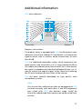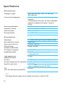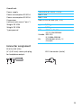
1
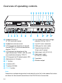
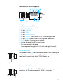
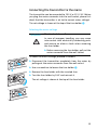
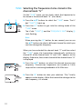
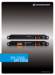
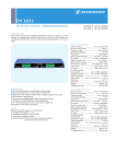
SR 3254
SR 3256
Instructions for use
4
SR 3254
SR 3256
Thank you for choosing Sennheiser!
We have designed this product to give you reliable operation
over many years. Over sixty years of accumulated expertise in
the design and manufacture of high-quality electro-acoustic
equipment have made Sennheiser a world-leading company in
this field.
Please take a few moments to read these instructions carefully,
as we want you to enjoy your new Sennheiser products quickly
and to the fullest.
Contents
Safety instructions ............................................................................ 6
SR 3254/SR 3256 transmitters ...................................................... 8
Delivery includes ................................................................................ 9
Overview of operating controls ....................................................10
Indications and displays .........................................................................11
Preparing the transmitter for use ................................................12
Using the transmitter as a stand-alone unit ......................................12
Rack-mounting several transmitters ...................................................13
Connecting the transmitter to the mains ............................................15
Using transmitters in a multi-channel system ...................................16
Using the transmitter .....................................................................18
Switching the transmitter on/off .........................................................18
The operating menu of the transmitter ......................................20
Overview of the operating menu ..........................................................21
Selecting the frequencies to be stored in the channel
bank “U” – TUNE .......................................................................................22
Selecting a channel from the channel
bank “U” or “F” – CHANNEL ....................................................................23
Switching between mono and stereo
operation – MONO/STEREO .....................................................................23
Care and maintenance ....................................................................24
Cleaning the transmitter ........................................................................24
Replacing the fuse ....................................................................................24
If problems occur ... .........................................................................26
Error checklist ....................................................................26
Additional information ...................................................................27
Specifications ...................................................................................28
Connector assignment ............................................................................29
Accessories .......................................................................................30
Safety instructions
y Please read these instructions carefully and completely
before using the transmitter.
y Make these instructions easily accessible to all users at all
times. Always include these instructions when passing the
transmitter on to third parties.
y Never open the transmitter, otherwise you can receive an
electric shock. If units are opened by customers in breach of
this instruction, the warranty becomes null and void.
y Keep the transmitter away from direct sunlight, central
heating radiators, electric heaters and similar sources of
heat. Ensure sufficient ventilation, especially when it is
mounted into a 19" rack.
y Water entering the housing of the transmitter can cause a
short-circuit and damage the electronics. Protect the
transmitter from damp and wet.
y Do not place any objects containing liquids on the top of
the transmitter.
y Use the transmitter in dry rooms only. Never expose it to
water (e.g. never place it in a position where it could be
subjected to water splashes).
y Only use a slightly damp cloth to clean the transmitter.
Attention! High volume!
This is a professional transmission system.
Commercial use is subject to the safety-at-work
regulations. Sennheiser, as the manufacturer, is
therefore obliged to expressly point out possible
health risks arising from use.
This system is capable of producing sound pressure exceeding
85 dB(A). 85 dB(A) is the sound pressure corresponding to the
maximum permissible volume which is by law (in some
countries) allowed to affect your hearing for the duration of a
working day. It is used as a basis according to the specifications
of industrial medicine. Higher volumes or longer durations can
damage your hearing. At higher volumes, the duration must be
shortened in order to prevent damage. The following are sure
6
signs that you have been subjected to excessive noise for too
long a time:
y You can hear ringing or whistling sounds in your ears.
y You have the impression (even for a short time only) that
you can no longer hear high notes.
Intended use of the transmitter
Intended use includes
y having read these instructions especially the chapter “Safety
instructions”.
y using the transmitter within the operating conditions as
described in these instructions.
Improper use
Improper use is when you use the transmitter other than
described in these instructions or when you use the transmitter
under operating conditions different from those described in
these instructions.
7
SR 3254/SR 3256 transmitters
With the wireless in-ear monitoring system, consisting of the
SR 3254 or SR 3256 stereo transmitter and the EK 3253
bodypack receiver, musicians, video and sound amateurs,
reporters/broadcasters, etc. can directly monitor the received
sound signals without troublesome cables or monitor speakers
being required. In addition, the system can also be used for any
application where talkback signals are to be transmitted.
The system has superb audio quality with an increased signalto-noise ratio and dynamic range due to the inclusion of
Sennheiser’s HDX noise reduction system.
The SR 3254 is a single stereo transmitter in a 19" 1 U housing.
4
SR 3254
The SR 3256 consists of two complete stereo transmitters in a
19" 1 U housing.
SR 3256
The stereo transmitters have the following features:
y Easy to use
y Stereo/mono selector switch
y Switching bandwidth of 36 MHZ per transmitter
y Transmission frequencies tunable in steps of 5 kHz
y HDX noise reduction system with more than 90 dB signal-tonoise ratio
y LC display for frequency, RF output power and deviation
y Rugged 19" housing with built-in mains unit; supplied with
rack-mounting kit
y Suitable for multi-channel applications
y RF output power of up to 100 mW
8
The channel bank system
The SR 3254/SR 3256 transmitter is available in five
UHF frequency ranges:
Range A:
Range B:
Range C:
Range D:
Range E:
518 to 554 MHz
626 to 662 MHz
740 to 776 MHz
786 to 822 MHz
830 to 866 MHz
The transmitter has two channel banks with up to 16
switchable channels each. The channels of the channel
bank “F“ (fixed bank) have been factory-preset to
customer-specific transmission frequencies. These
frequencies cannot be changed.
The channel bank “U” (user bank) allows you to freely
select and store frequencies.
Recommended receiver
y EK 3253
Delivery includes
y 1 SR 3254 transmitter or
1 SR 3256 twin transmitter
y 1 rack-mounting kit
y 1 mains cable
y 1 telescopic antenna (with the SR 3254)
or
2 telescopic antennas (with the SR 3256)
y Instructions for use
9
Overview of operating controls
Headphone output,
¼” (6.3 mm) jack socket
Fuse holder and mains voltage
selection (230 or 115 V)
Headphone volume control
2-pin IEC mains connector
LCD bargraph for deviation of the left
channel (DEV L), with overmodulation
display (“PEAK”)
Cable grip for mains cable
LCD bargraph for deviation of the
right channel and “MONO” (DEV R), with
overmodulation display (“PEAK”)
Audio input, left (AF IN (L))
LCD bargraph for RF output power (RF)
Alphanumeric LC display
SET button
Programming interface,
15-pin sub-D socket
Audio input, right
(AF IN (R) + MONO)
Type plate
Antenna output
왖 button (UP)
왔 button (DOWN)
POWER button
Note:
Connections and operating controls marked with a star () in the above illustration
are those for the second transmitter of the SR 3256 twin transmitter.
10
Indications and displays
Alphanumeric display
“FREQUENCY MHZ” display
“CHANNEL” display
LC dot CHANNEL
LC dot TUNE
LC dot MONO/STEREO
LC dot STEREO (transmitter is set to stereo operation)
LC dot MONO (transmitter is set to mono operation)
MUTE display (transmitter is muted)
6-step bargraph for RF output power
11-step deviation bargraph
(two separate bargraphs for the left and right channel)
Deviation display
The two bargraphs indicate the deviation of the audio signal
of the left and right channel. When the transmitter’s audio
input level is excessively high, “PEAK” lights up.
Display of the RF output power
The bargraph indicates the RF output power. During normal
operation, an RF output power of 100 % is indicated.
11
Preparing the transmitter for use
Using the transmitter as a stand-alone unit
Mounting the transmitter feet
To ensure that the transmitter cannot slip on the surface on
which it is placed, four self-adhesive soft rubber feet are
supplied.
왘 Ensure that the base of the transmitter is clean and free from
grease before mounting the rubber feet.
왘 Fix the rubber feet to the base of the transmitter by peeling
of the safety paper and fitting them as shown in the diagram
on the left.
Attention!
Some furniture surfaces have been treated with varnish,
polish or synthetics which might cause stains when they
come into contact with other synthetics. Despite a thorough
testing of the synthetics used by us, we cannot rule out the
possibility of staining.
Connecting the telescopic antenna
When using the transmitter as a stand-alone unit, connect the
supplied telescopic antenna !. The telescopic antenna can be
mounted quickly and easily and is suitable for all applications
where – good transmission conditions provided – a wireless
transmission system is to be used without a large amount of
installation work.
왘 Connect the telescopic antenna to the BNC socket at the
rear of the transmitter.
왘 Pull the end cap to extend the telescopic antenna.
Optimum transmission and reception conditions can be
obtained by using remote antennas (see “Mounting and
connecting remote antennas” on page 17).
12
Rack-mounting several transmitters
You can use the supplied rack mount “ears” to mount the
transmitter into a 19" rack (1 U). If you wish to mount the
antennas to the front of the rack, use the GA 3030-AM antenna
mount (see “Accessories” on page 30).
Setting up the transmitters
The SR 3254 and SR 3256 transmitters heat up during
operation.
y Ventilation in fixed installations
Ensure sufficient ventilation, especially when the transmitters
are mounted into a desk or chassis. Provide for a duct of
sufficient size to ensure a free air flow between the transmitters.
y Sufficient ventilation in a rack
When operating several transmitters in a rack, ensure
sufficient ventilation or cooling. We recommend not stacking
more than two transmitter directly one above the other, and
then providing for a duct of sufficient size to ensure a free air
flow between the transmitters.
Rack-mounting the transmitter without mounting the
antennas to the front of the rack
왘 Hook the two rack mount “ears” " to the rear of the
transmitter.
왘 Secure the rack mount “ears” to the left and right of the
transmitter using four recessed head screws respectively.
왘 Slide the transmitter into the 19" rack.
왘 Secure the rack mount “ears” " to the rack.
13
Rack-mounting the transmitter and mounting the antennas
to the front of the rack
왘 Mount the antenna holders
to the handles of the
transmitter as shown in the diagram on the left.
왘 Hook the two rack mount “ears” " to the rear of the
transmitter.
왘 Pull the cables of the antenna holders
in the rack mount “ears”.
through the holes
왘 Secure the rack mount “ears” to the left and right of the
transmitter using four recessed head screws respectively.
왘 Connect the cables of the antenna holders to the antenna
sockets at the rear of the transmitter.
왘 Slide the transmitter into the 19" rack.
왘 Connect the telescopic antennas to the BNC sockets of the
antenna holders .
14
Connecting the transmitter to the mains
The transmitter can be connected to 230 V or 115 V AC. Before
you plug the mains connector into the wall socket, please first
check that the transmitter is set to the correct mains voltage!
The set voltage is shown at the top of the fuse holder .
Selecting the mains voltage
WARNING!
Electric shock hazard!
In case of improper handling, you may come
into contact with electrically conducting parts
and receive an electric shock when removing
the fuse holder.
왘 Before removing the fuse holder, pull out the
mains connector from the wall socket.
To select the mains voltage, proceed as follows:
왘 Disconnect the transmitter completely from the mains by
pulling out the mains connector from the wall socket.
왘 Use a screwdriver to loosen the fuse holder .
왘 Remove the fuse holder with the inserted fuse.
왘 Turn the fuse holder by 180° and reinsert it.
The set voltage is shown at the top of the fuse holder.
15
Connecting the mains cable
왘 Insert the supplied mains cable into the socket on the
transmitter and pass the cable through the cable grip.
Note
A cable grip is particularly important when the transmitter is
permanently rack-mounted. Inside the rack there are often a
large number of cables – a cable grip prevents the cables
from pulling each other out.
Using transmitters in a multi-channel system
You can combine several transmitters to make a multi-channel
system. To do so, you require an antenna combiner (e.g. the
AC 3000, see “Accessories” on page 30) which allows you to
combine the signals of up to four twin receivers onto a single
antenna (see diagram below). For detailed information on
setting up a multi-channel system and on connecting the
transmitters, please refer to the operating manual of the
antenna combiner.
ANT
RF OUTPUT
8:1
16
Mounting and connecting remote antennas
Use a remote antenna when the transmitter position is not the
best antenna position for optimum transmission. You can
choose between two antennas (see “Accessories” on page 30):
y A 2003 UHF passive directional antenna
y A 1031 passive omni-directional antenna
A 2003
A 1031
Use a low-attenuation 50-Ω cable to connect the antenna to the
transmitter. Ready-made antenna cables from Sennheiser are
available as accessories with length of 5 m and 10 m. If possible,
use a short antenna cable and as little connections as possible,
since long cables and many connectors lead to an attenuation
of the antenna signal. Position antennas in the same room in
which the transmission takes place! Maintain a minimum
distance of 1 m from metal objects (including reinforced
concrete walls)!
Connecting the mixing console
Connect the mixing console to the XLR-3 sockets AF IN (L) and AF IN (R) + MONO .
Note
Any unit that is only suitable for mono operation must be
connected to the XLR-3 socket AF IN (R) + MONO . In this
case, set the transmitter to mono operation (see “Switching
between mono and stereo operation” on page 23).
17
Using the transmitter
Switching the transmitter on/off
왘 Press the POWER button to switch the transmitter on or
off.
After switch-on, the LC display is backlit and the last
transmission frequency set is displayed.
Until the PLL has locked on the desired transmission frequency,
the transmitter is muted. “MUTE” appears on the display and
the LCD bargraph for RF output power (RF) indicates 0 %.
Note
The POWER button works in the secondary circuit of the
integrated mains transformer, and thus only switches the
low voltage side. For larger installations with several
transmitters, a complete mains disconnection can best be
achieved by a central ON/OFF switch.
Connecting the headphones/monitoring the audio signal
Attention! High volume!
Even short exposure to high volume levels can damage your
hearing! Set the volume for the connected headphones to the
minimum before putting the headphones on. Do not listen at
higher volume levels than with loudspeakers.
왘 Connect headphones with a ¼“ (6.35 mm) stereo jack plug
to the headphone output to monitor the stereo audio
signal present at the audio inputs AF IN (L) and
AF IN (R) + MONO.
Note
Even during mono operation, the left and right channel are
reproduced separately via the headphones.
18
왘 First, set the volume control # to the lowest volume by
turning it to the left as far as possible. Then gradually turn up
the volume.
19
The operating menu of the transmitter
Via the operating menu, you can quickly and easily change the following settings:
Menu
Function of the menu
TUNE
Setting a transmission frequency for the channel bank “U”
(user bank)
CHANNEL
Selecting a channel from the channel bank “U” or “F”
MONO/STEREO
Switching between mono and stereo operation
The buttons
In the operating menu, all settings can be made using the 왖 , 왔 and SET buttons:
Buttons
왖/왔
Mode
Function of the button
Display mode Selects a menu.
Setting mode y Briefly pressing the button:
The display jumps either forwards or backwards to the
next setting.
y Holding down the button (“TUNE” and ”CHANNEL”
menu):
The display cycles continuously (“fast search”
function). The “fast search” function allows you to get
fast and easily to your desired setting.
SET
Display mode Changes to the setting mode of the selected menu.
Setting mode y Stores the setting and returns to the display mode.
y In the “TUNE” menu:
Confirms the selection of the channel for which you
want to set the frequency.
Canceling an entry
When in the setting mode of a menu, you can cancel your entry
at any time by pressing the 왖 and 왔 buttons simultaneously.
The cancellation is briefly confirmed on the display with “ESc.”.
The previous setting is kept and the transmitter returns to the
display mode.
20
Overview of the operating menu
Display mode
Setting mode
Press SET
for 1 sec.
SET
Current channel
: U 1... U 16, F 1... F16
SET: Selects the channel
SET
: Transmission
frequency in steps of 5 kHz
Current frequency
SET
SET
Current channel or current
frequency
Changing the channel
: U 1... U 16, F 1... F16
SET
SET
Switching between mono
and stereo operation
Current setting
: Mono, Stereo
SET
21
TUNE Selecting the frequencies to be stored in the
channel bank “U”
Via the “TUNE” menu, you can freely select the frequencies to
be stored in the channel bank “U” (user bank).
왘 Press the 왖/왔 buttons to select the “TUNE” menu. The LC
dot “TUNE” lights up.
왘 Press the SET button to get into the setting mode of the
“TUNE” menu.
The LC dot “TUNE” and the “FREQUENCY MHZ” display start flashing.
Note
When pressing the SET button for one second, you can use
the 왖/왔 buttons to select a different channel for which you
can then change the frequency.
When you have selected the channel bank “F” and then select
the “TUNE” menu, the transmitter automatically switches to
channel 01 of the channel bank “U” and “U.01” appears on the
display. Otherwise, the current channel of the channel bank “U”
is displayed.
왘 Press the 왖/왔 buttons to select the desired transmission
frequency. Transmission frequencies are tunable in 5-kHz
steps within a switching bandwidth of 36 MHz max.
왘 Press the SET button to store your selection. “Sto.” briefly
appears on the display. While the transmitter changes to the
new frequency, it is muted.
22
CHANNEL Selecting a channel from the channel bank “U”
or “F”
왘 Press the 왖/왔 buttons to select the “CHANNEL” menu.
The LC dot “CHANNEL” and the “CHANNEL” display light
up.
왘 Press the SET button to get into the setting mode.
왘 Press the 왖/왔 buttons to select the desired channel.
1 Sek.
왘 Press the SET button to store your selection. “Sto.” briefly
appears on the display.
MONO/STEREO Switching between mono and stereo operation
왘 Press the 왖/왔 buttons to select the “MONO/STEREO” menu.
The LC dot “MONO/STEREO” lights up.
왘 Press the SET button to get into the setting mode.
왘 Press the 왖/왔 buttons to select the desired operating mode.
왘 Press the SET button to store your selection. “Sto.” briefly
appears on the display.
23
Care and maintenance
Cleaning the transmitter
CAUTION!
Water can damage the electronics of
the transmitter!
Water entering the housing of the transmitter
can cause a short-circuit and damage the
electronics.
왘 Only use a slightly damp cloth to clean the
transmitter.
왘 Before cleaning, disconnect the transmitter from the mains.
왘 If necessary, you can clean the transmitter with a slightly
damp cloth. Do not use any cleansing agents or solvents.
Replacing the fuse
WARNING!
Electric shock hazard!
In case of improper handling, you may come into
contact with electrically conducting parts and
receive an electric shock when removing the
fuse holder.
왘 Before removing the fuse holder, pull out the
mains connector from the wall socket.
왘 Disconnect the transmitter completely from the mains by
pulling out the mains connector from the wall socket.
왘 Use a screwdriver to loosen the fuse holder .
왘 Remove the fuse holder with the inserted fuse.
왘 Replace the fuse by a new fuse with the same rating.
왘 Reinsert the fuse holder. Make sure to insert the fuse holder
the correct way round.
The set voltage is shown at the top of the fuse holder.
왘 Reconnect the transmitter to the mains and and switch it on
again.
24
If the replacement fuse also blows, please contact your local
Sennheiser agent or send the transmitter, with a precise
description of the trouble, to a Sennheiser service partner in
your area. You can find the address of your nearest service
partner in the enclosed service card or on the Internet at
“http://www.sennheiser.com/sennheiser/icm.nsf/root/
service_partner”.
25
If problems occur ...
Error checklist
Problem
Possible cause
Possible solution
No operation indication
No mains connection
Check the connections of
the mains connector
Fuse is defective
Replace the fuse
Transmitter and receiver
are not on the same
channel
Set transmitter and
receiver to the same
channel
Transmitter is out of
range
Change the antenna
position
Transmitter is set to
mono operation and the
pilot tone evaluation of
the receiver is activated
Deactivate the pilot tone
evaluation on the receiver
Receiver’s squelch
threshold is adjusted too
high
Reduce the squelch
threshold on the receiver
Transmitter sensitivity is
adjusted too low or too
high
See “Connecting the
mixing console” on
page 17
No RF signal
RF signal available,
no audio signal
Audio signal has a high
level of background
noise or is distorted
If problems occur that are not listed in the above table or if the problems cannot be
solved with the proposed solutions, please contact your local Sennheiser agent for
assistance.
26
Additional information
HDX noise reduction
RF link
Inherent
noise of
the RF link
Transmitter
Receiver
Progress you can hear:
The product family is equipped with HDX, the Sennheiser noise
reduction system that reduces RF interference. It increases the
signal-to-noise ratio in wireless audio transmission to more
than 90 dB.
HDX is a wideband compander system which compresses the
audio signal in the transmitter in a 2:1 ratio (related to dB) to
lift it above the inherent noise floor of the RF link. In the receiver
the signal is expanded in an identical and opposite way in a 1:2
ratio to restore the original signal, at the same time reducing
the RF noise to below the noise floor of the receiver.
HDX has been specially developed for high quality radio
microphone systems.
Note:
Only transmitters and receivers that are equipped with HDX
can work correctly with each other. If non HDX equipment
was mixed with HDX, the dynamic range would be
drastically reduced and the transmission would sound blunt
and flat.
27
Specifications
RF characteristics
Frequency ranges
518–554, 626–662, 740–776, 786–822,
830–866 MHz
Transmission frequencies
1 channel bank with up to 16 factory-preset
channels
1 channel bank with up to 16 freely selectable
channels (frequencies tunable in steps of
5 kHz)
Switching bandwidth
36 MHz
Frequency stability
±10 ppm (-10° C to +55°C)
Antenna output
BNC socket, 50 Ω
RF output power
max. 100 mW
AF characteristics
Modulation
FM stereo working on the pilot tone principle
Noise reduction system
Sennheiser HDX
Nominal/peak deviation
±24 kHz / ±48 kHz
MPX pilot tone
(frequency/deviation)
19 kHz / ±5 kHz
AF frequency response
40–15,000 Hz
Headphone output
¼“ (6.35 mm) stereo jack socket,
≥ 200 mW/32 Ω
Load impedance of
headphone output
≥ 16 Ω
AF input
2 x XLR-3, electronically balanced
AF input voltage (at nom. deviation) +4 dBu at 1 kHz, internally adjustable
Signal-to-noise ratio
> 90 dB(A)rms
(refers to overall link with EK 3253)
THD
(at 1 kHz and nominal deviation)
< 0.9 %
Note:
The above data also apply to the second transmitter in the SR 3256.
28
Overall unit
Power supply
115/230 V AC +10% / –15%
Power consumption SR 3254
max. 13 W
Power consumption SR 3256
max. 23 W
Dimensions
(without rack mount “ears”)
436 x 228 x 43 mm (19", 1 U)
Weight SR 3254
approx. 3,300 g
Weight SR 3256
approx. 4,000 g
Type approval
USA:
FCC-Part 74.861
FCC ID: DMOSREK3K
Canada: RSS-123
IC: 2099A-SREK3K
EU:
ETSI EN 300 454-1/-2
CE 0682!
Connector assignment
SR 3254/SR 3256
¼“ (6.35 mm) stereo jack plug
for headphone output
XLR-3 connector (male)
+
2
1
3
29
Accessories
AC 3000-EU Active Antenna combiner Cat. no. 009424
AC 3000-UK Active Antenna combiner Cat. no. 009410
AC 3000-US Active Antenna combiner Cat. no. 094409
A 1031-U Passive omni-directional antenna Cat. no. 004645
GA 3030-AM Antenna mount Cat. no. 004368
A 2003 UHF Passive directional antenna Cat. no. 003658
GZL 1019 A5 BNC-BNC coaxial cable, length 5 m Cat. no. 002325
GZL 1019 A10 BNC-BNC coaxial cable, length 10 m Cat. no. 002326
GZV 1019A BNC coupler Cat. no. 002368
HD 25 Monitoring headphone Cat. no. 002976
EK 3253 A Monitoring receiver Cat. no. 500522
EK 3253 B Monitoring receiver Cat. no. 500523
EK 3253 C Monitoring receiver Cat. no. 500524
EK 3253 D Monitoring receiver Cat. no. 500525
EK 3253 E Monitoring receiver Cat. no. 500526
30
Warranty regulations
The guarantee period for this Sennheiser product is 24 months from
the date of purchase. Excluded are accessory items, rechargeable or
disposable batteries that are delivered with the product; due to their
characteristics these products have a shorter service life that is
principally dependent on the individual frequency of use.
The guarantee period starts from the date of original purchase. For this
reason, we recommend that the sales receipt be retained as proof of
purchase. Without this proof (which is checked by the responsible
Sennheiser service partner) you will not be reimbursed for any repairs
that are carried out.
Depending on our choice, guarantee service comprises, free of charge,
the removal of material and manufacturing defects through repair or
replacement of either individual parts or the entire device.
Inappropriate usage (e.g. operating faults, mechanical damages,
incorrect operating voltage), wear and tear, force majeure and defects
which were known at the time of purchase are excluded from
guarantee claims. The guarantee is void if the product is manipulated
by non-authorised persons or repair stations.
In the case of a claim under the terms of this guarantee, send the
device, including accessories and sales receipt, to the responsible
service partner. To minimise the risk of transport damage, we
recommend that the original packaging is used. Your legal rights
against the seller, resulting from the contract of sale, are not affected
by this guarantee.
The guarantee can be claimed in all countries outside the U.S. provided
that no national law limits our terms of guarantee.
EC Declaration
of Conformity
This equipment is in compliance with the essential requirements and
other relevant provisions of Directives 1999/5/EC, 89/336/EC or 73/
23/EC. The declaration is available on the internet site at
www.sennheiser.com.
Before putting the device into operation, please observe the respective
country-specific regulations!
31
Sennheiser electronic GmbH & Co. KG
30900 Wedemark, Germany
Phone +49 (5130) 600 0
Fax +49 (5130) 600 300
www.sennheiser.com
Printed in Germany
Publ. 08/05
513631 / A01