1
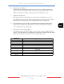
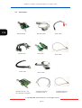
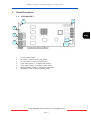
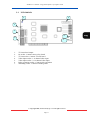
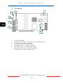
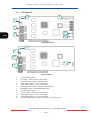
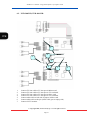
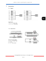
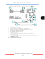
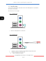
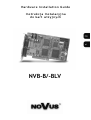
Hardware Installation Guide
Hardware Installation Guide
Instrukcja Instalacyjna
d o ka r t w i z y j n y c h
NVB-B/-BLV
DVR-user’s manual—integrated software of Capture Card
© Copyright 2005, Novus Security Sp. z o.o. All rights reserved
Page 2
Hardware Installation Guide
NVB-B/-BLV
DVR-user’s manual—integrated software of Capture Card
TABLE OF CONTENTS:
1.
2.
3.
4.
5.
6.
7.
PREFACE ……..……………………………………………….………….5
SPECIFICATION OF NVB-B/-BLV ...….………………………………...6
INSTALLATION NOTE …..…………...………………………………….8
PRODUCTS AND COMPONENTS ………………………………………9
BOARD DESCRIPTION …....…………………………………..………..11
INSTALL BOARD ..…………………………..………………………….17
ACCESSORIES …………………………………..………….…………...19
Technical modification are subject to change without prior notice. Misprints reserved.
© Copyright 2005, Novus Security Sp. z o.o. All rights reserved
Page 4
DVR-user’s manual—integrated software of Capture Card
1.
Preface:
This is a guide book that explains the hardware components and provides you the step by
step installation of DVR board.
For the software explanation please refer to “Installation and User’s Guide”.
The pictures and names of the products are subject to change depending on hardware
upgrade. But, the usages may be similar.
© Copyright 2005, Novus Security Sp. z o.o. All rights reserved
Page 5
DVR-user’s manual—integrated software of Capture Card
2.
Specification of NVB-B/-BLV:
1.
1~32 Camera inputs/output
Up to 16 camera inputs are available on screen for digital handling.
- Normal input condition: 75 Ohm, 1 Vp-p
2.
1~16 Sensor inputs
Up to 16 sensors can be linked to the system.
- Power supply of DC 12 Volt is required from outside.
3.
1~4 Digital outputs (Relay outputs)
Digital Outputs can be used to activate things like shutters and sirens, and activation
can be linked to sensor and motion detection.
4.
Sound recording and Two-way communication capability
Sound can be recorded with video images. Two-way communication is possible
between DVR_Main and DVR_Net.
5.
Display feature (with Multi-viewing)
Multi-Viewing allows 1, 4, 6, 9, 10, or 16 different camera shots to be displayed
onscreen at the same time. Other display features include enlarging all displayed
cameras or just one. 32 channel viewing can be attained with specially configured
cards.
6.
PAN/TILT/ZOOM/FOCUS Capabilities
Each connected camera can be manipulated through the DVR_Main program as long
as each camera supports such capabilities.
7.
Auto Rebooting System
When DVR detects an error or malfunction within the system, it will automatically
reboot the system in order to correct it.
8.
Motion Detection and Sensor Trigger
Detection features make it possible to record images only when movement is
detected, preserving volume space and maximizing the use of physical storage space.
9.
Scheduled Recording
Scheduling allows the administrator to record images only during designated time
periods, if so desired.
Every combination of scheduling is available in the DVR program.
© Copyright 2005, Novus Security Sp. z o.o. All rights reserved
Page 6
DVR-user’s manual—integrated software of Capture Card
10.
Manual and Auto Backup
Data can be preserved through various formats (DAT, CD, or DVD) and data from
specific cameras and/or time periods can be specifically isolated for backup as well.
Much like scheduled recording, backup of data can be scheduled as well.
11.
Digitalized Video Search
Recorded data features digital playback for each camera simultaneously or one at a
time. Playback features include advanced search features and image extracting, which
allows portions of existing video to be extracted and saved as a separate file.
12.
Network Support (PSTN, TCP/IP, LAN ,Modem Protocol Support) DVR supports
network access, which allows administrators to login to DVR_Main and remotely
access all the features provided locally.
13.
POS, Access Control, ATM Support
Record data from external devices (POS, Access Control, ATM, etc) with DVR video
images. Text Search allows to search data from external devices with DVR video image
when event occurs. This will raise the level of integrity and security
Function
Camera Input
Specification
1~16(32)Port(NTSC/PAL)
Sound Input
Sensor Input
Relay Output
Composite Output
Image Format
Recording Mode
1, 2, 4, 16 Port
16 Port
4 Port
1 Port (NTSC/PAL, Split, Switching )
MPEG
Watch, Normal, Motion Detection, Sensor, scheduled
Recording
Full remote control PSTN, ISDN,ADSL, LAN and TCP/IP
DAT, CD, DVD
RS-232/422/485 Interface
Remote Control
Back-up
PAN/TILT/ZOOM/
FOCUS
© Copyright 2005, Novus Security Sp. z o.o. All rights reserved
Page 7
DVR-user’s manual—integrated software of Capture Card
3.
Installation Note:
1.
Recommend to use Intel Chipset mother board (i845, i865– without i845G, i865G ,
i9xx ).
a)
Not compatible with mother boards that are specifically designed such for
Small
Form Factor (SFF-Mobile).
b)
Recommended to use ASUS, Gigabyte and Intel Mother boards.
2.
Recommend Intel Pentium 4 2.4 or higher for CPU.
a)
CPU that is lower than Intel Pentium 4 2.4 can reduce the recording frame
rate.
3.
Recommend 512MB or above system memory.
a)
Less than 512MB of memory may bring down the overall system performance.
4.
Recommend ATI Redeon 9000 or higher.
a)
Using video card lower than ATI Redeon 9000 may affect the recording data.
b)
Intel onboard Extreme II VGA is an alternative.
5.
Recommend 120GB or larger hard driver.
a)
Install the latest Service Pack when using 160GB or larger hard drive.
6.
Install Direct X 8.0 or higher.
a)
Under Windows 2000, must install Direct X 8.0 or higher for sound recording.
(In Windows XP, Direct X 8.0 is installed as default.)
7.
Disable screen saver and Standby mode.
a)
Turn off System Standby mode.
b)
Turn off Screen saver.
c)
Turn off all the energy saving feature.
8.
PC Specification for 32 channels capture card (NVB-400/32B):
a)
Motherboard with chipset 9xx, Intel, Gigabyte, ASUS;
b)
1 GB RAM
c)
HDD S-ATA.
d)
Intel Pentium 4 3GHz
© Copyright 2005, Novus Security Sp. z o.o. All rights reserved
Page 8
DVR-user’s manual—integrated software of Capture Card
4.
Products and Components:
4.1
DVR Board:
NVB-200/16BLV
NVB-100/16BLV
NVB-200/16B
NVB-100/16B
NVB-200/32B - Master
NVB-200/32B - Slave
NVB-400/32B - Master
NVB-400/32B - Slave
© Copyright 2005, Novus Security Sp. z o.o. All rights reserved
Page 9
DVR-user’s manual—integrated software of Capture Card
4.2
Accessories:
RS-485 Board
RS-232C Cable
Pigtail Cable
Sensor Port
Video Cable
RS-485 converter + TVOUT board for 32 channel
Audio Cable
Reset Cable
Sensor Cable
32 channel TV-OUT
connection Cable 1
32 channel TV-OUT
connection Cable 2
© Copyright 2005, Novus Security Sp. z o.o. All rights reserved
Page 10
DVR-user’s manual—integrated software of Capture Card
5.
Board Description:
5.1. NVB-200/16BLV:
2
1
3
4
6
5
7
1.
2.
3.
4.
5.
6.
7.
TV-Out select Jumper
IO socket : Connect sensor, relay board
TV-Out socket : Connect TV-Out board
Video input socket : 1~8 channel video input
Video input socket : 9~16 channel video input
Relay expansion socket : Connect relay expansion
Watchdog socket : Connect watchdog cable
© Copyright 2005, Novus Security Sp. z o.o. All rights reserved
Page 11
DVR-user’s manual—integrated software of Capture Card
5.2. NVB-100/16BLV:
1
2
3
4
6
5
7
1.
2.
3.
4.
5.
6.
7.
TV-Out select Jumper
IO socket : Connect sensor, relay board
TV-Out socket : Connect TV-Out board
Video input socket : 1~8 channel video input
Video input socket : 9~16 channel video input
Relay expansion socket : Connect relay expansion
Watchdog socket : Connect watchdog cable
© Copyright 2005, Novus Security Sp. z o.o. All rights reserved
Page 12
DVR-user’s manual—integrated software of Capture Card
5.3. NVB-200/16B:
1
2
3
4
6
5
7
1.
2.
3.
4.
5.
6.
7.
TV-Out select Jumper
IO socket : Connect sensor, relay board
TV-Out socket : Connect TV-Out board
Video input socket : 1~8 channel video input
Video input socket : 9~16 channel video input
Relay expansion socket : Connect relay expansion
Watchdog socket : Connect watchdog cable
© Copyright 2005, Novus Security Sp. z o.o. All rights reserved
Page 13
DVR-user’s manual—integrated software of Capture Card
5.4. NVB-100/16B:
3
1
2
4
5
7
6
8
1.
2.
3.
4.
5.
6.
7.
8.
TV-Out select Jumper
External TV-OUT socket : Connect to TV-OUT port in back panel.
IO socket : Connect sensor, relay board
TV-Out socket : Connect TV-Out board
Video input socket : 1~8 channel video input
Video input socket : 9~16 channel video input
Relay expansion socket : Connect relay expansion
Watchdog socket : Connect watchdog cable
© Copyright 2005, Novus Security Sp. z o.o. All rights reserved
Page 14
DVR-user’s manual—integrated software of Capture Card
5.5. NVB-200/32B:
1
2
3
4
6
5
7
MASTER Board
8
9
10
12
11
SLAVE Board
1.
2.
3.
4.
5.
6.
7.
8.
9.
10.
11.
12.
TV-Out select Jumper
IO socket : Connect sensor, relay board
TV-Out socket : Connect TV-Out board
Video input socket: 1~8 ch. video input
Video input socket: 9~16 ch. video input
Relay expansion socket: Connect relay expansion
Watchdog socket: Connect watchdog cable
TV-Out select jumper
TV-Out socket : Connect TV-Out board
Video input socket: 1~8 ch. video input
Video input socket: 9~16 ch. video input
TV-OUT board connect socket : Connect to TV-OUT board
© Copyright 2005, Novus Security Sp. z o.o. All rights reserved
Page 15
DVR-user’s manual—integrated software of Capture Card
5.6. NVB-400/32B:
1
2
3
4
6
5
7
MASTER Board
8
9
10
12
11
SLAVE Board
1.
2.
3.
4.
5.
6.
7.
8.
9.
10.
11.
12.
TV-Out select Jumper
IO socket : Connect sensor, relay board
TV-Out socket : Connect TV-Out board
Video input socket: 1~8 ch. video input
Video input socket: 9~16 ch. video input
Relay expansion socket: Connect relay expansion
Watchdog socket: Connect watchdog cable
TV-Out select jumper
TV-Out socket : Connect TV-Out board
Video input socket: 1~8 ch. video input
Video input socket: 9~16 ch. video input
TV-OUT board connect socket : Connect to TV-OUT board
© Copyright 2005, Novus Security Sp. z o.o. All rights reserved
Page 16
DVR-user’s manual—integrated software of Capture Card
6.
Install Board:
6.1. NVB-100/16B, NVB-200/16B, NVB-100/16BLV, NVB-200/16BLV:
1
2
3
4
5
1.
2.
3.
4.
5.
1~8 channel pigtail goes to the upper socket.
9~16 channel pigtail goes to the lower socket.
IO cable connects to Sensor port.
IO cable connects to IO socket on the DVR board.
Connect Watchdog cable.
Make Watchdog cable connection as shown in next figure.
© Copyright 2005, Novus Security Sp. z o.o. All rights reserved
Page 17
DVR-user’s manual—integrated software of Capture Card
6.2. NVB-200/32B, NVB-400/32B:
1
2
7
44
66
1.
2.
3.
4.
5.
6.
7.
3
Connect TV-Out cable to TV-Out port in Master card.
Connect TV-Out cable to TV-Out port in TV-out board.
Connect TV-Out cable to TV-Out port in Slave card.
Connect TV-Out cable to TV-Out port in TV-out board.
Connect white cable to left side of jumper in Slave card.
Connect white cable to the pin. (black cable goes to empty side)
Connect CCTV monitor.
© Copyright 2005, Novus Security Sp. z o.o. All rights reserved
Page 18
5
DVR-user’s manual—integrated software of Capture Card
7.
Accessories:
7.1. Pigtail:
Pigtail cable
1 ~ 4, 9 ~ 13 : Black BNC
5 ~ 8, 13 ~ 16 : White BNC
7.2. Sensor Port:
Sensor port pin number
1 ~ 8, 9 ~ 16 : Signal input
G : Ground
4, 3, 2, 1 : Relay output
© Copyright 2005, Novus Security Sp. z o.o. All rights reserved
Page 19
DVR-user’s manual—integrated software of Capture Card
7.3. RS232 to RS422/485 Converter:
2
1
3-1
3
3-2
5
1.
2.
3.
4.
5.
6.
4
Connect to system’s Com port.
Connect to PTZ port converterRS-485.
These are power supply sockets. Need to connect only one of them.
When you choose to use included power supply cable connect this to 3-2.
Connect to DVR board.
If one of power supplies(3, 3-1) has been connected there is no need to connect this
cable.
RS-485 Mode
RS-422 Mode
© Copyright 2005, Novus Security Sp. z o.o. All rights reserved
Page 20
DVR-user’s manual—integrated software of Capture Card
7.4. RS232 to RS422/485 Converter + TV-OUT board for 32 channel:
1
3
2
3-1
6
4
5
8
7
3-2
9
10
1.
2.
3.
4.
5.
6.
7.
8.
Connect to system’s Com port..
Connect to PTZ port converterRS-485 + TV-OUT board
These are power supply sockets. Need to connect only one of them.
TV-Out socket : Connect to Master card.
TV-Out socket : Connect to Slave card.
Connect to Slave card.
When you choose to use included power supply cable, connect this to 3-2.
Connect to DVR board.
If one of power supplies(3, 3-1) has been connected there is no need to connect
this cable.
9.
Connect to 4 or 5 socket.
10. Connect to Master or Slave card.
© Copyright 2005, Novus Security Sp. z o.o. All rights reserved
Page 21
DVR-user’s manual—integrated software of Capture Card
7.5. Sound Recording:
After connecting Microphone, ensure that “Line In” and “Microphone In” is not muted in
the Windows sound setting.
Must have Direct X 8.0 or higher.
7.5-1. 1 Channel sound
1
1. Connect to “Microphone In” of sound card.
7.5-2. 2 Channel sound
2
1.
2.
Connect to “Line In” of sound card with included 2 channel audio cable.
Connect microphones to the audio cable.
Must use amplified microphone.
© Copyright 2005, Novus Security Sp. z o.o. All rights reserved
Page 22
DVR-user’s manual—integrated software of Capture Card
7.5-3. 4 channel sound
3
1.
2.
3.
4
Additional sound card is needed (total 2 sound cards – 1 onboard and 1 PCI).
Connect “Line In” in both sound cards with included 2 channel audio cable.
Connect microphones to the audio cables.
Must use amplified microphones.
* Using 3 channels is the same as picture shown above.
© Copyright 2005, Novus Security Sp. z o.o. All rights reserved
Page 23
DVR-user’s manual—integrated software of Capture Card
© Copyright 2005, Novus Security Sp. z o.o. All rights reserved
Page 24
NOVUS Security Sp. z o.o.
Pulawska Street 431, 02-801 Warsaw, Poland
phone.: (22) 546 0 700, fax: (22) 546 0 719
www.novuscctv.com
2005-10-28.