1
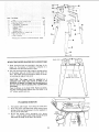
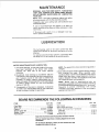
MODEL NO.
113.239201
SHAPER ONLY
113.239390
SHAPER WiTH STEEL
LEGS AND MOTOR
Serial
Number
Model and serial
number may be found
on the front of
the table.
You should record both
model and serial number
in a safe place for
future use.
WOOD
CAUTaON:
Read GENERAL
and ADDITIONAL
SAFETY
• assembly
e operating
iNSTRUCTIONS
carefully
Sold by SEARS,
Part No. 72036
SHAPER
o repair
ROEBUCK
AND
parts
CO.,
Chicago,
IL. 60684
U.S.A.
Printed
in USA.
.......
_L,_l_J¸¸
....
general
I.......
rr'l .........
-
-II
.....
i ¸ I li
instructions
safety
•
for
power
tools
1. KNOW YOUR POWER TOOL
Read
and
understand
the
owner's
manual
and
affixed
to
the tool.
Learn
its application
and
limitations
as wetl as the specific
potential
hazards
peculiar to this tool,
2. GROUND
3. KEEP GUARDS
in working
alignment.
and
in
proper
adjustment
KEYS
Cluttered
areas
and
must not be slippery
benches
of
Keep proper
footing
15. MAINTAIN
and batance
at all times_
TOOLS WITH CARE
Keep
tools
performance_
sharp
and clean
Follow
instructions
for
best and
for lubricating
safest
and
invite
accidents.
tools
7. KEEP CHILDREN
should
in
damp
kept
or wet
locations
Consult
or
lighted,
a safe distance
from
work
the
19. NEVER
switches,
or
by
removing
as
position
before
plugging
owner's
ACCESSORIES
manual
for
recommended
that accompany
accessories may
injury
cutting
tool
to do a job
if the tool is tipped
materials
to stand on the tool
above or near the tool
DAMAGED
operate
for
proper(y
alignment
or if the
contacted,
Do no_ store
Check
for.
such that
to reach them.
PARTS
aguard or other part that
checked to ensure that it
and perform
of moving
its intended
parts, binding
function.
of mowng
parts,
breakage
conditions
that
of parts,
may .affect
mounting,
and any
other
its operation.
A guard or
other
_s damaged
should
part
that
be properly
repaired
or replaced.
21.
DIRECTION
Feed work
of rotation
(Head Protection)
Wear Safety goggles (must
comply with ANSI
Z87:1)
at all times,
Everyday
eyeglasses only have impact
resistant
lenses, they are NOT safety glasses. Also, use
face or dust mask if cutting operation
iS dustY, and ear
occur
Before further
use of the tool,
is damaged should be carefu!ly
it was not
Do not wear loose clothing,
gloves, neckties or iewefry
(rings, wrist
watches)
to get caught
in moving
parts.
Nonslip
footwear
is recommended,
Wear protective
hair covering
to contain
long hair, Roll long sleeves
above the elbow,
could
is accidentaJly
_I is necessary
will
or attachment
GOGGLES
STAND ON TOOL
Serious
20. CHECK
and safer at the rate for which
11. WEAR PROPER APPARE L
12. USE SAFETY
such
STARTING
is in "OFF"
accessones
Follow
the {nstructions
the accessories.
The use of improper
cause hazards,
TOOL
tool
accessories
In,
KID-PROOF
master
tt wttl do the job better
_t was designed.
force
ACCIDENTAL
sure switch
18. USE RECOMMENDED
9. DON'T FORCE TOOL
10. USE RIGHT
Make
changing
AWAY
be
8. MAKE WORKSHOP
with
padlocks,
starter keys.
TOOLS
servicing;
when
bits, cutters, etc.
t7. AVOID
Floor
ENVIRONMENT
them
to rain. Keep work area well
adequate sui'rOunding
work space.
All vtsltors
area.
before
blades,
due to wax or sawdust.
DANGEROUS
use power
designed
periods
WORK
16. DISCONNECT
5. KEEP WORK AREA CLEAN
Don't
extended
14. DON'T OVERREACH
and
Form habit of checking to see that keys and adjusting
wrenches are removed from toot before turning
tt on.
expose
Provide
during
changi ng accessories.
4. REMOVE ADJUSTING
AND WRENCHES
Don't
or muffs)
Use clamps or a vise to hold work when practical.
It's
safer than using your hand, frees both hands to operate
tool,
IN PLACE
order,
(plugs
13. SECURE
ALL TOOLS
This tool is equipped
with an approved
3-conductor
cord and a 3-prong
grounding
type plug to fit the
proper grounding
type receptacle.
The green conductor
m the cord is the grounding
wire. Never connect the
green wire to a live terminal,
6, AVOID
protectors
operation,
labels
OF FEED
into a blade or cutter against
of the blade or cutter only,
22. NEVER LEAVE TOOL
UNATTENDED
:
Turn power off.
complete stop.
Don't
the direction
RUNNING
leave tool
until
it comes
to a
ADDiTiONAL
SAFETY iNSTRUCTIONS
FOR WOOD SHAPER
CAUTION:
Turn
Power
Cord
adju st ments.
motor
when
switch
changing
"OFF"
Shaper
and
disconnect
cutters
or
making
19, NEVER
perform
freehand
shaping
- Use either
the
fence, or a starting pin in the table and a collar on the
spindle, or a pattern.
Safety
is a combination
of operator
common
sense and
alertness at all times when the Wood Shaper is being used,
20. Do not place your
material being cut.
WARNING:
FOR
YOUR
OWN
SAFETY,
DO
NOT
ATTEMPT
TO OPERATE
YOUR WOOD SHAPER
UNTIL
IT
IS COMPLETLY
ASSEMBLED
AND
INSTALLED
ACCORDING
TO THE INSTRUCTIONS...
AND UNTIL
YOU
HAVE
READ
AND
UNDERSTAND
THE
21. NEVER
perform
irregular
shaping operations
with
cutter
guard removed.
Be positive
it is installed
adjusted per instructions.
the
and
22. NEVER
Shaper.
this
FOLLOWl
23. Do not use your hands to remove
from around cutters; use a brush.
NG:
PAGE
1.
2.
3.
4.
General Safety Instructions for Power Tools
Getting to Know your Wood Shaper ............
Basic Wood Shaper Operation
.................
Maintenance
..............................
5.
Stability
.....
2
12
15
19
of Machine
The Shaper must be bolted securely to a stand or work
bench,
in addition,
if there is any tendency
for the
Shaper to tip over or move during certain operations,
it
should be bolted to the floor.
6.
Location
7.
Protection:
Eyes, Hands,
Face, Ears, Body
Wear safety
goggles that
comply
with
ANSI
Z87.1
1968. Wear ear plugs or muffs during extended
periods
of operation.
Do not wear gloves ... roll long sleeves
above the elbow.
8.
Afways
feed against
rotation
"back
up" the workpiece.
9.
of
the
Do not take deep cuts or feed the stock
cutter.
too
NEVER
rapidly.
10. Be particularly
careful
in shaping wood that
cross grains or knots, as these may cause the
be thrown into the cutter or cause kickbacks.
contains
hands to
11. Before applying
power,
make sure the keyed washer is
installed
immediately
under the spindle
nut and the
spindle nut is securely fastened, and all guards are in the
proper position.
Make sure cutters are sharp.
12. Avoid
awkward
hand positions, where a sudden slip
could cause a hand to move into the cutter. Never reach
in back of or around the cutter with either hand to hold
down
24. Do not tamper
in any way.
internal
with
26. NEVER
attempt
work pieces.
source,
to
operations
objects
on
of
or materials
make them
inoperative
shape warped
or twisted
or bowed
has stopped
revofving.
29. If any part of this
or fai! in
Shaper
should
break,
bend,
on
any way or any electrical
component
fail to perform
properly,
or if any is missing, shut off power switch,
remove
power
supply
cord from
power
supply
and
replace
damaged
missing and/or
failed
parts before
resuming operation.
WARNING:
DO NOT ALLOW
FAMILIARITY
(GAINED
FROM FREQUENT
USE OF YOUR WOOD SHAPER)
TO
BECOME
COMMONPLACE.
ALWAYS
REMEMBER
THAT
A CARELESS
FRACTION
OF A SECOND
IS
SUFFICIENT
TO INFLICT
SEVERE
INJURY.
30. Note and follow
Shaper fence.
Safety
Instructions
WAR
A KEYED
that appears
on the
NING
WASHER
BE USED
UNDER
MUST
THE
31. Note and follow
Safety
Shaper Switch assembly,
ALWAYS
SPINDLE
NU'i"
instructions
that
appear
on the
DANGER
FOR YOUR OWN SAFETY:
READ
2
14. Rubbish,
shavings, stock, or other objects or material
should not be allowed on the floor where they may be a
tripping
hazard.
BEFORE
WEAR
t6.
When the fence is used, make sure it is securely
and will not slip, and is properly adjusted.
t7.
Do not wear gloves, neckties, loose sleeves, or ragged or
torn
clothing
of
any
kind.
Wear safety
goggles
complying
with ANSI
Z87.1-1968
to protect your eyes
from dust or flying
particles.
layout,
the cutting
assembly,
toot
or set-up
is rotating.
fastened
work
on
OWNE_4
OPERATING
SAFE_'P¢ GOGGLES
ANSI Z87 1
TIM_S
ALL
UND_.R
SF'INDLE
,NUT
AND
1_ DIRECTLY
SP_NDL_
_VLiT lS
T_G_TB_FORE TU_I_G S_A_E_
3
ALWAYS
ROTA:tON
_EED
O_
_N SAME
AW?;WARD
K_P
F;N_RS
CUTTER
ON
VVORKPI_CE
AGAIN$1
CUT/,_
MOTOR
._t_D
ROTATE
4 AVOID
5
S
_,_AC_4_NE
pen
BE POSIT_V_ K]_Y_D W_.$HER
CU'FTER
15. Use working
forms,
patterns
or
holders
wherever
possible,
and keep them maintained.
Care should
be
taken
that
the work
is securely
fastened
in these
fixtures.
Stock is often of such size or shape that it
must be clamped
in a holder before being shaped, The
inside jaws which
clamp directly
against the stock
should be lined with sand paper. Guards may also be
mounted
on a holder to afford additional
protection.
UNDE{_TANb
*&_D
M_tNUAL
AT
perform
nor
and the cutter
rotating.
NOT
guards
edge
cover
the workpiece.
table while
shaping
near
28. Never operate the Shaper without
a protective
the unused shaft end of a double ended motor.
_
the
hands
27. Before leaving the machine, make sure the motor switch
is "OFF"
the power cord is disconnected
from
the
13. Accumulations
of stock or of finished work should not
be allowed on the table. Never clear table while cutter is
18. DO
or
25. ALWAYS
joint or plane edge on surface of workpiece
that will be in contact with fence and/or table.
power
The
Shaper
should
be positioned
so neither
the
operator
nor a casual observer is forced to stand in line
with
the workpiece
when straight
line shaping.
This
Shaper is intended
for indoor use only.
perform
fingers
_)t_CT_DN
NAND POS_T_D_4$
AWAY'
,-- USE
I:ROM
_VOLVtNG
F_XTUR_S
W_4E_
NECESSARY
_5 USE OV_R_4_AD
ABLE
€_NC_
GUARD
_$ NOT
IN
WHEN
AOJUS'€.
PLA_E
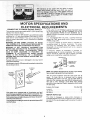
WARNING: THE 4-318" FLAT MOTOR PULLEY AND THE
2" SPINDLE PULLEY FURNISHED, WILL RUN THE CUT TER APPROXIMATELY 9000 R. P.M. WH EN USED WITH A
3450 MOTOR. NEVER SUBSTITUTE THESE PULLEYS
TO INCREASE THIS SPEED BECAUSE IT COULD BE
DANGEROUS.
Note and follow
motor.
safety instructions
CAUTION:
before
using,Reversible motor
that appear on the
- check rotation
ii 'can: 'reSult: in foreign
which::can
result in
before cornmencing
Sears
E LE CTRICA
CONNECTING
TO POWER SOURCE
This machine
must be grounded
operator from efectr:ic shock.
while
OUTLET
in use to protect
Plug power cord into a 120V properly
protected
by a t5 amp dual element
If the outlet
the
adapter as shown
known ground.
tt
sure that your
by a qualified
NOT
PERMIT
FINGERS
TO TOUCH
OF PLUGS
WHEN
INSTALLING
OR
PLUG TO OR FROM
THE OUTLET,
cord is worn or cut, or damaged
immediately.
to use for this power
type DO
PRONG
and
is recommended
replace
THREE
NOT REMOVE
OR
IN ANY
MANNER.
always
that
the TWO
prong
prong outlet.
connect
you
outlet
have
with
the grounding
a qualified
tool
is
ALTER
Use an
lug to
electrician
a properly
grounded
A temporary
adapter
as shown
below
is available
for
connecting
plugs
to 2=prong
receptacles.
The green
grounding
tug extending
from
the adaptor
must
be
connected
to a permanent
ground
such as to a properly
grounded
outlet box.
WARNING:
IF
NOT
PROPERLY
GROUNDED
THIS
POWER
TOOL CAN INCUR
THE
POTENTIAL
HAZARD
OF
ELECTRICAL
SHOCK.
PARTICULARLY
WHEN
USED
IN :DAMP
LOCATIONS
|N
PROXIMITY
TO
PLUMBING.
IF A:N ELECTRICAL
SHOCK
OCCURS
THERE
IS THE
POTENTIAL
OF
A SECONDARY
HAZARD
SUCH AS YOUR
HANDS
CONTACTING
THE
CUTTER
BLADE.
If power
replaced
you are planning
of the two prong
THE GROUNDING
grounded type outlet
time delay or circuit
saver fuse or circuit
breaker. If you are not
outlet is properly
grounded,
have it checked
electrician.
WARNING:
DO
THE TERMINALS
REMOVING
THE
L:IREQU! R EIV! ENTS
A temporary
adapter
as
illustrated
is available
for
connecting
plugs to 2-prong
receptacles,
The temporary
adapter
should
be used only until a properly
grounded
outlet can be installed
by a qualified
electrician.
GROUNDING
LUG
in any way, have it
Yourshaper
is wired for 120 volts and h_s a plug th at looks
the one shown below.
MAKE
3-PRONG
PLUG
like
KNOWN
SURE
THISIS
GROUND
2*PRONG
RECEPTACLE
3-PRONG
PLUG
ADAPTE
R
NOTE: The adapter illustrated is for use only if you already
have a properly grounded 2-prong receptacle.
PROPERLY
GROUNDED
OUTLET
The use of any extension
cord will cause some loss of
power,
To keep this to a minimum
and to prevent
overheating
and motor
burn-out,
use the table below to
determine
the minimum wire size (A.W.G,) extension cord.
Use only
3 wire extension
cords which have 3-prong
grounding
type plugs and 3-pote receptacles which accept
the tools plug.
@
GROU NDING
PRONG
Extension
Cord
Length
0-25
FT .................................
26-50
FT ...............................
51-100 FT ................................
l_his power tool is equipped with a 3_conductor cord and
grounding type plug listed by Underwriters" Laboratories. The
ground conductor has a green jacket and is attached to the
tool housing at one end and tothe ground prong in the attachment plug at the other end.
This plug requires a mating 3-conductor grounded type outlet
as shown above.
MOTOR
16
14
12
ROTATION
The
motor
is
counterclockwise
the other bythe
the motor.
4
Wire Size AWG
designed
to rotate
either
clockwise
or
and can be changed from one rotation to
use of a select switch located on the side of
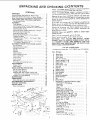
UNPACKING
AND CH ECKING
CO NTENTS
Model
113.239390
Wood
Shaper
is shipped complete
one carton and includes
st:eel
legs and motor.
.... : ................................
Instruction
for Power
Tools
2
2
..........
Additional
Safety Instructions
for Wood Shaper ......
Motor Specifications
and Electrical
Requirements
....
UNPACKING
AND
CHECKING
CONTENTS
.......
List of Loose Parts
..............................
ASSEMBLY
......................................
Tools Needed
...................................
Installing
Mounting
Installing
Elevating
Rod and Table Support
........
Belt Guard and Motor to Motor Mount
Motor Pulley
...........................
Mounting
Mounting
Assembling
Mounting
Plugging
Motor Support
Assembly
to Shaper
.....
Switch Assembly
......................
Steel Legs
..........................
Wood Shaper on Floor Stared ..........
in Motor
..............................
Installing
Shaper Fence -- For Straight
Edge
Shaping only .................................
installing Shaper Cutter Guard --- For Curved
or Irregular
Shaping
only
.....................
GETTING
TO KNOW
YOUR: WOOD
SHAPER
On-Off
Switch
.................................
Elevating
Control Lever
.........................
Spindle
Lock Knob
.............................
Spindle
........................................
Spacers
.......................................
Keyed Washer
.................................
Fence Adjusting
Knob
..........................
Fence Lock Knob
...............................
Fence Faces ...................................
Cutter Guard
...................................
3
4
5
5
6
6
..
7
7
8
9
9
9
10
10
11
....
11
12
12
13
!3
t3
t3
13
13
t3
t3
13
Starting
Pin ....................................
Removing
and Installing
Cutter
..................
ADJUSTMENTS
................................
13
13
14
Shaper Fence ..................................
Fence Faces
...................................
BASIC SHAPING
OPERATIONS
!4
14
15
.................
Use of Cutter Spacers
..........................
Straight
Edge Shaping
..........................
Shaping With Use of Miter
Gauge and
Hold-Down
Clamp (Optional
Accessory)
........
Irregular
or curved Shaping
.....................
MAINTENANCE
.................................
LUBRICATION
..................................
Motor Maintenance
and Lubrication
.............
RECOMMENDED
ACCESSORIES
...............
TROUBLE
SHOOTING
...........................
REPAIR
PARTS
.................................
Motor Connections
.............................
O
t5
16
16
17
19
19
t9
19
20
22
27
Model
113.239201
Wood
one carton
but DOES
NOT
Shaper
is shipped complete
in
INCLUDE
Steel Legs or Motor.
Separate al! parts from
p_oking
one with the illustration
and
the
certain all items are accounted
materials
and check each
tist of Loose Parts to make
for, before discarding
any
packing material.
If any parts are missing,
do
not attempt
to assemble
the
Shaper, plug in the pov_er
cord or turn the switch on until
the missing parts are obtair_ed
and are installed correctly.
Remove
the
protective
oil
and edges of the t_ble.
grease and spot remover.
CAUTION:
Never use
volatile solvents.
Apply
that
Use
is applied
any
g,asoline,
a coat of automobilJe
Wipe aH parts thoroughly
naptha
wax
with
to the
ordinary
table top
household
or
similar
type
highly
to the table.
a clean,
dry cloth,
WARNING:
FOR
yOUR
OWN
SAFETY,
NEVER
CONNECT
PLUG TO POWER
SOURCE
OUTLET
UNTIL
ALL ASSEMBLY
STEPS
ARE
COMPLETE,
AND
YOU
HAVE
READ AND
UNDERSTAND
THE SAFETY
AND
OPERATIONAL
INSTR
UCT_ONS.
LIST
Included
Item
A
B
C
D
E
F
G
H
J
K
L
M
N
O
P
Q
R
S
T
with
Model
OF
LOOSE
No.
113.23920t
PARTS
and
113,239390
Part Name
Motor Mount
Qt_/.
.............................
CONTENTS
WARRANTY
General Safety
in
Guard, Pulley .............................
Pulley, Motor .............................
Belt, "V" 1/2 x 33: ...........................
t
1
1
Support A_sembfy, _H
.....................
Support Assembly, L.H ......................
Guard, Cutter
.............................
Hub Assembly, Lock
.......................
Nut, Lock ...............................
Stud Nut ..................................
Support, Guard ............................
Bracket, Support
...........................
Fence Assembly ............................
Plate, Guard ................................
Switch Box Assembly
......................
Spin_fe Assembly ..........................
Base
1
1
t
t
1
1
1
I
1
I
1
1
Owners Manual
............................
Bag Assembly, Loose Parts
Containing The Fo_llowing:
Starting Pin
Insert, Table ............................
Wre rich
Screw, Hex Hd. 3/8-16;
I
(Part No. 72022)
1
I
1
2
x 1
====================
2
Bolt, Carriage 5/t6-18
× t-1/4
..............
Washer 21164 i.D. x 71B O.D. x 1/8 ..........
Screw, W/L0ckv_asher
5716-18 x 3/4
.........
Washer 11/32 I.D. x 1 - !/16 x 1,/8 ............
Wrench, Hex "L °' 5132
......
* .............
Wrench, Hex *'L'" I/4
Knob
4
4
3
2
1
3
Nut, He× 5/16-t8
L0ckwasher, Int. 5I:t _;................
Han_er, Cable
- .....................
7
3
Screw0 H ex H_1."5"1:I_: lj'_ 1"2
Elevating Rod
1
2
..............
................
,
i,,"
':'
_ ..
"
H
tnclude
.i ¸¸ .
Item
A
B
C
D
E
F
G
H
J
K
L
M
H
• : ;.:
PartName
0_.
Leg
• S++e+,"ii&+_+.+;
+i+++++'_
+;+: i:i:i:i;::ii
++
eNut, Hex 1]4-20 ._+++ ..... ....:.;: ........
2B o L0ckwasher, 114 External ...................
2B
Channel, Support ....................... 2
Stiffener ..............................
2
Stiffener, Side ..........................
2
Stiffener; End ..........................
2
• Screw, Pan lid. Ty. A N8 x 1/2 ............
4
• Nut, Flex Hd. t/2-13 ....................
B
• Foot, Leveling ......................... 4
Motor ................................
1
+
B
s
"; [
1
liARDWARE FOR MOUNTING TOOL
"
•
•
•
Screw,liex lid. 5/16-18 x 3 ...............
Lockwasher, 5116External ...............
Nut, Hex Jam 5/16-1B ...................
Washer,ti/32 ID .......................
• These parts
contained
3
3
3
3
f
N
in Loose Parts Bag No, 72031.
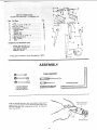
ASSEMBLY
7tI6++NCH
WRENCH
1/2-INCH
WRENCH
9116-1NCH
WRENCH
Coat the spindle assembly
with cup grease, being sure to
wipe some of the grease into tf+e elevating
stot miffed in the
spindle
assembJy,
Use a generous
amount
of grease to
cover the spindle.
TAPPED HOLE FOR
ELEVATING
ROD
SLOT
-
?
i ¸
SPINDLE
PULLEY
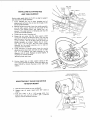
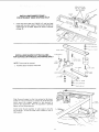
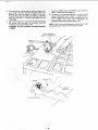
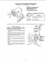
INSTALLING
ELEVATING
ROD
AND TABLE SUPPORT
Position
table upside down on 2 x 4's on edge for support
and clearance for Spindle assembly.
1.
Install
(3/8-24)
jam nut on short
elevating
rod and screw the rod into
side of spindle assembly.
2.
Remove spindle lock knob. Insert the spindle assembly
into the table support,
position
the long angle of the
elevating
rod
straight
down
and
tighten
jam
nut
securely.
The angle portion of elevating
rod must be
parallel with spindle assembly.
3.
Install
4.
Rotate
the set screw into
the table support,
while
moving the elevating
rod back and forth, until the dog
point on end of set screw enters the elevating
slot in
spindie assembly.
This can be felt as the set screw and
spindle
assembly
are rotated.
Tighten
the set screw,
then back it off
1/4 turn.
This will allow
enough
clearance
for the spindle
assembly
slot to slide on
dog-point
end of set screw.
5.
Check operation
of spindle
several times, by moving
elevating control
lever back and forth in order to make
sure it is not binding,
yet slides effectively
on the
dog-point
end of screw. Readjust
set screw slightly,
if
required, for smooth operation.
knob
Reinstall
,
on end of elevating
spindle
threaded
end of
the threads in the
rod.
lock knob.
Position shaper base on table support
casting so the
three mounting
holes are aligned. Install and tighten the
three 5/!6-18
× 3/4-inch
hex-head
screws with
lock
washers.
POSITION
MOTOR WITH
51"8 IN. DIA, SHAFT TI41S END
BELT GUARD
MOUNTING
BELT GUARD
TO MOTOR
MOUNT
1.
Place the motor
2.
Support
shown.
3.
Find four
5/16"
x 18 x 1-1/4 carriage
5/16-18
hex nuts, and two 21/64
x 3/4
Washers. Position hardware as shown.
rear
mount
AND MOTOR
of
motor
on your
mount
workbench.
with
3/4"
stock
bolts,
x t/16
as
four
Flat
MOTOR
3/4
IN, STOOl<
t/16 IN.THiCK
WASHERS
MOUNT
5/16
INHEXNUTS
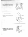
INSTALLING
1.
MOTOR PULLEY
Install motor pulley (flat-faced
pulley) on motor shaft,
with closed end of pulley facing out. Tighten pulley set
screw securel y.
5132
SETSCREW
f
/"
MOTOR
IN,
WRENCH
PUL LEY
F LUSH W{TH
SHAFT
_IOTOR
2.
MOiNT
PLATE
MOTOR
Using table insert as a spacer, position
motor on motor
mount
plate to provide
a distance
of 1/4-inch
from
mounting edge of motor mount plate as shown. Tighten
the four motor
mount
bolts securely
and recheck for
correct positioning.
MOTOR
/
TABLE INSE RT
USED AS A SPACER
1/4
INCH
£ULLEY
MOUNTING
MOTOR
SUPPORT ASSEMBLY
MOTO
R
TO SHAPER
MOTOR
1.
Place V-belt on motor
pulley and attach motor mount
plate to shaper base with
two bolts (3/8-16
x 1-inch)
and washers. Leave bolts finger tight.
2.
Roll the belt onto spindle
pulley,
pull motor
mount
plate toward
end of base until belt is tight enough to
prevent
slipping and tighten
the two bolts. Each bolt
should
be in approximately
the same position
in the
base slots.
3o
Position elevating
rod in approximate
mid position
and
turn spindle pulley by hand several times to see that the
belt rides in the approximate
mid position
of motor
pulley.
If not,
recheck
assembly.
The belt should
change positions on motor pulley as the lever position
is
changed (while the spindle pulley is rotated by hand).
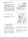
MOUNTING
Attach
the
switch
assembly
ASSEMBLING
two
to
the
screws
STEEL
(Supplied with 113,239390
2.
3,
PLATE
SPINDLE
PULLEY
BASE
SWITCH ASSEMBLY
Shaper table
using the
packed with the switch.
1.
ELEVATING
ROD
MOUNT
underside
of
the
and Iockwashers
LEGS
only)
Assemble
the two (2) End Stiffeners
and the two (2)
Side Stiffeners
using four (4) 1/4_20 Truss head screws.
The End Stiffeners
are placed on top of each Side
Stiffener
as shown.
Insert screws through the 9/32 inch
diameter
holes and finger tighten 1/4-20 nuts.
Attach
the four (4) legs to the side and End Stiffener
using 1/4-20 screws, _ockwashers and nuts as shown.
Remove
the four
(4) Truss head screws which
were
assembled
in Paragraph
No. One. Place the two
(2)
Support
Channels as shown, in position,
align holes in
supports
with
holes
in the side Stiffeners,
replace
tockwashers
and nuts. Tighten
all nuts using 7/16"
wrench,
4. The two
of each
screws.
screws.
(2) Stiffeners,
side stiffener
The guard
(F) are fastened to the top side
using N8 x t/2 self-threading
plate
is mounted
as shown
using same
5. Install
leveling feet as shown. To ieve! Leg Set, ]oosen
nut on inside of leg and turn nut on outside to raise or
lower feet. Adjust a_l four levelers, if necessary, and then
tighten
NOTE:
nuts on inside
These
adjustment.
of leg.
levelers
are
not
intended
for
height
Item
A
B
C
D
E
F
G
H
j
K
L
Qty,
Part Name
Leg .... ..........
_
e Screw, TrussHd. l/4_20xS]8
.,. .....
.,...
• Nut. Hex 1/4_20 , .. .....................
Lockwasher, _/4 E xternat
................
Channel. Support ........................
Stiffener
...............................
Stiffener, Side
........................
Stiffener, End ..........................
o Screw, Pan Hd•Ty. A N8 × t/2 ............
o Nut. Hex Hd. 1/2-13
....................
• Foot, Leveling
.........................
• These
parts contained
in Loose
4
28
28
28
2
2
2
2
4
8
4
Parts Bag No. 72031•
IL
GUARD
PLAT_
SHAPER ONFLOOR
MOUNT,NG
WOOD
STAND
_' t,
Three
mounting
holes are provided
in the base of the
:shaper
for the purpose
of moundng
it securely
on a
substantial
tool stand with screws or bolts,
2. The t0ol:stand
of the:shaper
should be high enough so the top surface
table wilt be '35 to 37 inches: above the
floor. The Shaper must be mounted
to overhang:_ear
edge Of tooi stand,
to allovy
the motor
NO,
PAN
:
(SUPPLIED
CAUTIONi
Substantial
:
:: '
The
toot:: stand
andi: secured
so:ithere:
8 x
HD.
WITH
1/2 IN.
SCREW
LEG
SET)
on a
is _ no
possibility of tlpping;The
Shaper:must be positioned on
the tool stand so that the spindle pulley is guarded from
the bottom:
: :i'
:" i:/::
:::
i'
'i:
::::
:
"......................
PIace the Shaper On: the Steel LEGS. Position as shown,
and align mounting
h01es_ Secure with 3 e& 5/16"x
18
x 3" screws; washers and nuts.
PLUGGING
IN MOTOR
MOTOR
1,
Find
plastic
2,
Route
the
cable hanger from
motor
cord behind
among
the
motor
the
loose parts.
mount,
across
the top of the Leg Set and plug it into the receptacle
the side of the switch box.
3.
Bring
cord..,
in
CABLE
HANGER
the
power
cord
alongside
the
motor
wrap the plastic cable hanger around the cords
and attach
the hanger to the top
of the Leg Set.
CORD
lO
CORD
5/16-18
X 2 IN,
HEX HD. SCREWS
AND
WASHERS
FENCE
INSTALLING
FOR STRAIGHT
SHAPER FENCE -EDGE SHAPING ONLY
Install the fence with two 5/16-18
x 2 inch hex head
screws and two plain washers. These screws thread into
tapped
holes in the table, Adjust
the fence as outlined
on page 13.
GUARD
INSTALL! NG SHAPER CUTTER GUARD FOR CURVED OR IRREGULAR
SHAPING ONLY
NOTE:
1.
Fence must
Assemble
Cutter
]/4-28
SUPPORT
LOCI(NUT
be removed.
Guard
as illustrated.
L.H,
SUPPORT
t
Align the guard support
so that it is centered on the shaper
spindle
(it may be necessary to loosen the 5/t6-18
screws
which
secure the support
bracket
to the channels
to
perform
this adjustment).
After the alignment
is achieved
tighten all four screws securely.
install
Cutter
Guard Assembly
to table
two 5/t6-18
× 2 inch hex head screws
support
located
using the
at rear of
table support,
11
SHAPER
10 cwrTE_
GUARD
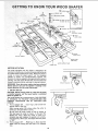
8
FENCE
LOCK KNOB
_
SP|NDLE
_:6
KEYED
NUT
"_"_.
WASHER
9¸
FENCE
FACE
J_
5
SPACERS
[2 EACH
7/'t6
IN,)
_"-"_
11 STArTiNG PIN
TABLE
7 FENCE
!__
_X'/4
_)
ADJUSIING
SPINDLE
KNOB
CONTROL LEVER
ELEVATING
]
SPINDLE
1
ON-OFF
LOCK
MOTOR (NOT
\
FURNISHED)
MOTOR
SHAPER
MOTOR
MOUNT
PLATE
BASE
ROTATION
The motor equipped
with, the shaper is designed to be
operated in a clockwise or counterclockwise
r0tation by use
of a select switch tocated on the motor. Before the motor is
@
turned on, move the select switch
"up"
for clockwise
rotation or "'down"
for counterclockwise
rotation.
The
direction
of rotation
cannot be changed while the motor is
running. Turn the motor off and wait until the motor has
stopped completely
before selecting the desired rotation:
WARNING!
always
correct
1.
Once
the motor
rotation
check to be sure the spindle
direction
for the cutter
being
ON-OFF
KEY
(YELLOW
_LAST]C}
has been selected
i_s rotating
used.
in the
SWITCH
CAUTION:
Before turning switch on, make sure the cutter
is installed
properly
and the keyed washer is positioned
below the spindle nut.
The On-Off Swi,tch has a locking feature. THIS FEATURE
IS INTENDED
TO PREVENT
UNAUTHORIZED
AND
POSSIBLE
HAZARDOUS
USE
BY CHILDREN
AND
OTHERS.
a.
TO turn
and pull
Shaper ON...
insert finger
END of lever out.
under switch
After turning
switch
ON, always
allow
come Up to full speed before cutting.
the
cutter
KEY
lever
to
Do not cycle the motor
switch
on and off rapidly,
as
this may cause the cutter to loosen. In the event this
should
ever occur,
allow
the cutter
to come
to a
complete stop and retighten
the spindle nut normally,
not excessively. Never leave the shaper while the power
is "'ON,:
b.
KNOB
SWITCH
TO turn Shaper OFF...
shaper until the cutting
stop.
PUSH lever in. Never leave the
tool has come to a complete
12
c. TO lock switchin OFFposition..,holdswitchIN
withonehand.,. REMOVE key with other hand,
Provides
added protection
for irregular shaping.
is adjustable for various thickness of material.
ALWAYS
LOCK
THE SWITCH "OFF"
WHEN
SHAPER IS NOT IN USE...
REMOVE KEY AND
KEEP IT IN A SAFE PLACE,,.
ALSO...
tN THE
EVENT OF A POWER FAILURE
(ALL OF YOUR
LIGHTS GO OUT) TURN SWITCH OFF .,, LOCK IT
AND REMOVE THE KEY. THIS WILL PREVENT
THE SHAPER FROM STARTING UP AGAIN WHEN
THE POWER COMES BACK ON,
2,
ELEVATING
CONTROL
CAUTION:
Always
rotate the spindle by hand before
starting the shaper motor to make sure cutter does not
strike guard.
11. STARTING
LEVER
depending
ALWAYS
12. REMOVING
SPINDLE
LOCK KNOB - used to lock the spindle and
quill
assembly
after
the desired
height
has been
determined.
CAUTION:
Always
release the quill
lock knob before
attempting
to change the position
of spindle and
tighten the knob securely before starting operation.
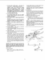
4.
SPINDLE
This
maximum
2-1/2-inch
diameter
bore.
5.
SPACERS
- A total of three spacers are provided,
two
7/16 inch thick and one 1/4 inch think for positioning
the cutter for desired shapes.
KEYED
WASHER
Must
always
immediately
below the spindle nut.
7.
FENCE
ADJUSTING
moved
forward
adjusting
knobs.
8.
FENCE
position
tightening
9.
LOCK
or
KNOB
-
be
upon
the
direction
on the in-feed side.
AND
CUTTERS
Raise spindle
b.
To REMOVE
cutter, hold spindle with the t/4" hex
wrench
and loosen nut with
wrench
provided
as
shown -- Reverse procedure to TIGHTEN
SPINDLE
NUT.
CAUTION:
under
the
Always
have
nut, otherwise
height
serious injury could
the keyed washer directly
the nut may loosen and
result.
positioned
by
turning
the
the
desired
fence
fence
After
has been selected,
the
the fence lock knobs.
fence
is secured
face
IN,
HEX
WRENCH
\
by
FENCE
FACES
- Each fence may be moved forward
or backward
by releasing
the fence lock knob
and
turning
the fence adjusting
knobs.
Each fence face
operates
independently
of the other, by means of the
adjusting
mechanism.
After the desired fence position
has been selected, it is secured by tightening
the fence
lock
knob.
The fence faces wilt
close in from
a
LOOSE
N
/
t/
maximum
three-inch
opening
down
to one-inch
for
small diameter
cutters, by loosening
the two screws in
the front of each face and sliding the face to the desired
posiiton.
The screws must be tightened
securely
after
each setting.
TI GHTE N
CAUTION: The opening between inner ends of fence faces
should never be larger than required to just clear the
particular cutter being used. ALWAYS ROTATE THE
SPINDLE BY HAND BEFORE STARTING THE SHAPER
MOTOR TO MAKE SURE CUTTER DOES NOT STRIKE
FENCE FACES.
10. CUTTER
but
Each fence face may be
backward
-
rotation,
a.
1/'4
KNOB
INSTALLING
to maximum
of
NOTE:
TO AVOID
POSSIBLE
BENDING
OF THE
SPINDLE
LOOSEN
OR TIGHTEN
NUT WITH BOTH
WRENCHES
POINTING
AS NEARLY
tN THE SAME
DIRECTION
AS POSSIBLE.
shaper
is designed
for use with
diameter cutters having a 1/2-inch
6.
PIN
The Starting
Pin must be used as a pivot to support the
work until it has been fed into the cutter and against
the collar. The Starting
Pin may be located in either of
the two threaded
holes near the table insert opening,
The
Elevating
Control
Lever
moves the
spindle
vertically
a distance of 7/8-inch
to locate the cutter at
the desired vertical position.
3.
Guard
WRONG
GUARD
NOTE:
Used for curved or irregular
fence
must be removed
and starting
place on in-feed side.
shaping onlypin must be in
R_GHT
13
,!,,
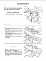
ADJUSTMENTS
WARNING:
FOR YOUR OWN SAFETY, TURN SWITCH
"OFF"
AND REMOVE PLUG FROM POWER SOURCE
OUTLET BEFORE MAKING ANY ADJUSTMENTS.
ADJUSTABLE
I,
SHAPER FENCE
Move both
fence faces
fence adjusting knobs.
out
3/4"
by turning
the two
:STRAIGHT
EDGE
FENCE
Position
fence
framing
square
adjusting knob.
2.
.
faces in the same plane by using a
or straightedge and adjusting the fence
Loosen the fence attaching bolts and shift the complete
fence assembly
until both fence faces are the same
distance from the miter slot,
Tighten
fence
attaching
correctly positioned.
Check this adjustment
sure it did not change,
bolts
:
after
fence
after:' tightening
:
;
Lock all controls
securely
I_een completed ....
after: :desired
has been
bolts to make
settings have
:i
FENCE FACES
t.
Loosen the four (4) screws as shown and slide each
fence face in as close to the cutter as possible, but do
not permit the cutter to strike fence faces.
2.
Set the fence faces so the cutter (Not supplied see
Recommended
Accessory
List)
projects
far enough
beyond
them to produce the desired depth of cut, If
the cutter is set to remove only a portion
of the edge of
the work piece, the two fence faces should be set even
with each other.
!4
FACE
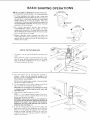
BASIC
SHAPING
OPERATmONS
NOTE: This shaper is designed
for use with maximum
2t/2 inch diameter cutters having a 1/2 inch diameter
bore.
1. For those
operators
who
prefer
to
use a motor
that
rotates clockwise
(facing pulley end) which would drive
the spindle
in a clockwise
direction the motor select
switch
should
be in the
up position.
With
this
combination,
the work would be fed into the cutter from
the left-hand
side of the table. In most cases, the cutter
would have to be turned over.
2. For
those
operators
which
may
require
counterclockwise
rotation
of the spindle,
the motor
select switch should be in the down position
and with
this combination
the work should be fed into the cutter
from the right side of the shaper.
3. Always
remember,
wllen
mounting
the cutter,
the
cutting edge of the cutter must lead into the direction
of
rotation
and the work piece must be fed against
the
direction
of the cutter
SPINDLE
USE OF CUTTER
The spacers
cutter.
can be
SPACERS
positioned
below
and
above
the
_
Notice when the spacer is positioned
below the cutter
how the spacer provides a bearing surface for the uncut
edge of the board, in addition
to its use as a spacer in
vertica! positioning
of the cutter,
2.
This
same cutter
can
be
inverted
produce
a shape with
the board
opposite
direction
IF DIRECTION
THE SPINDLE
tS REVERSED.
and
Notice how the spacer again provides
for the uncut edge of the board,
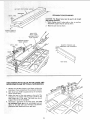
3.
a bearing
Feed workpiece
against
to
the
OF
be as
to use the Shaper for sizing
using the jointer
cutter and
rotation
of cutter.
NOTE:
It is a very good practice to make a trial cut on
a piece of scrap wood as a doubte check on the set-up
before using the actual workpiece.
WAR NING:
Serious injury may result
not always fed into the cutter against
rotation
of the cutter,
Use a smooth
Experience
will soon reveal the best
producing
the smoothest
cut,
5.
if workpiece
is
the direction of
even pressure.
rate of feed for
If the cut removes material
over the entire edge, thus
reducing
the width of the workpiece,
set the out-feed
fence in front of (toward the operator)
the m-feed face
enough to provide a contact surface for the work after
it passes the cutter, This setting
support the workpiece.
is necessary
DIRECTION
KEYED
WASHER
_"NCUTTER
surface
Cut the workpiece
to size, so the shaping cut will
light as possible to produce the desired pattern.
CAUTION:
Do not attempt
a workpiece
{except when
adjustable fence).
4.
mounted
fed through
in
OF ROTATION
SPACER
TtON
OF
ROTATION
to properly
15
OF
FEED
A'JX
WC_KPIECE
STRAIGHT
27 IN;
EDGE SHAPING
CAUTION: The Shaper fence must be used in all straight
edge shaping operations.
I; When shaping stock 3 inches wide or _ess, an auxiliary
fence/work Support must be used as shown.
2.
Make the push stick
as shown.
SLIGHTLY:THICK'ER
THAN
WORKPlECE
PUSH
STICK
(FEEDS UNDER
AUXILIARY
FENCE/
WORK SUPPORT
AUXILIARY
WORK
FENCE/
\
SUPPORT
SLIGHTLY
NARROWER
THINNER
AND
THAN WORKPIECE
FENCE
N
2O
PUSH STICK
WORKPIECE
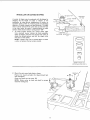
END SHAPING WITH USE OF MITER GAUGE AND
HOLD-DOWN CLAMP (OPTIONAL
ACCESSORIES)
1.
NEVER
use the Miter Gauge on the Shaper without
the
Hold-down
Clamp installed and the workpiece
clamped,
2,
Both fence faces MUST
cannot contact them.
3,
Adjust
the head of the miter gauge so the end of the
workpiece
to be shaped wil! be exactly
parallel to the
miter gauge slot in the table,
This holds true for all
be positioned
so the workpiece
angles of the end of the workpiece,
4.
The board is positioned
in the miter gauge; then hold
:::the w0rkpiece firmly
against the miter gauge head and
:doWn
on the table with your left hand, and feed by
::gripping the lock handle with your right hand.
/:i::::::i::
i/5
<.
:;,
;:::i:i:ii
¸:¸7:¸
i¸
•
t6
IRREGULAR
OR CURVED
SHAPING
[
A variety
of shapes may be produced
with the shaper by
changing
the the
height
of cutter
in relation
to the
workpiece,
by using various combinations
of cutters
on
successive passes, and/or
by inverting
cutter and changing
direction
of spindle rotation
and feed direction.
The table
insert must be removed if the cutter does not clear the hole
in the insert when the cutter is lowered
below
the table
surface:
1.
check
clearance
before
turning
switch
OF
(
"° _
°
SPINDLE
NUT
"ljj -,, ...,.__SPACER
wAs,,R
\ _. I.
"ON":
To make irregular
shaping cuts remove
power
cable
from
electrical
source,
remove
the fence assembly,
select the shaper collar that will position the cutter to
obtain the desired pattern, and lock the shaper collar
and cutter on the spindle,
SHAPER COLLAR
ACCESSORY)
(OPTIONAL
O
NOTE:
A shaper collar may be located above or below
a cutter, or between the two cutters selected.
O
SHAPER
COLLAR
(OPTIONAL
f
2.
Mount
the cutter
guard and adjust
Position
the Guard
clear workpiece)
Center
the Guard
verticatlV
over the cutter.
NOTE:
Rotate cutter
clearance inside guard.
by
hand
STARTIN G J
as shown.
(A)
(Guard
should
just
(B)
and check
for
proper
17
SET
ACCESSORY)
Workpiece
MUST contact
collar L_ toward the miter
5_
4,
WARNING:
LUMBER.
DO NOT ATTEMPT
of the cutter and
addition,
the following
operations are some which
performed::or_:
the shaper - shaping with
a
NOTE:I After a few hours of operation, tighten both
t screws securely with the Hex wrenches provided.
TO SHAPE WARPED
PIVOT
AROUND
In
the FRONT
gauge slot.
pattern, l,t0ngue and groove joints, reading and fluting,
etc:.
(" Power
Tool
Know
How"
Handbooks
are
available ).See Recommended
Accessories
st.
:_:l_
'
:
The starting pin must be used asa pivot to support the
work untillit has been :fed intothe :s_a_r col ari:Tlie
Starting:Pin
may
the:i:tw6
threaded holes "ear:the' table insert:oPening;: depending
upon i the: direction
0f :r0tatloni:: buti_aiways 0_ :the
in-feed side;
'
3.
WORKP|£CE
STARTING
PIN
18
pulley
MAINTENANCE
WARNING:
FOR YOUR OWN SAFETY, TURN SWITCH
"OFF"
AND REMOVE PLUG FROM POWER SOURCE
OUTLET BEFORE MAINTAINING
OR LUBRICATING
YOUR SAW.
NOTE: After a few hours of operation, tighten both pulley
set screws securely with the Hex wrenches provided.
Frequently clean your cutting tools with Craftsman Gum
and Pitch Remover.
A coat of automobile-type
wax applied to the table wilt
help to keep the surface clean and allow workpieces
to slide
more freely,
if the power cord is worn or cut, or damaged
have it replaced immediately.
in any way,
LUBRICATION
The ball bearings
used on the cutter
spindie
packed with lubricant
at the factory and require
attention,
To maintain
smooth
and easy operation,
few drops of oil to the outside
MOTOR
MAINTENANCE
have been
no further
occasionally
of the spindle
add a
assembly,
AND LUBRICATION
1. The sleeve bearings,
in both end shields of the motor,
have
been
lubricated
at the factory
with
correct
lubricant.
No.
other
part
of the
motor
requires
lubrication.
NOTE: The speed
changed.
4.
2. Re-lubricate
motor bearings
in accordance
with
the
instructions
on the nameplate.
Be sure to wipe off dirt or
grit if present
around
oil hole caps to prevent
any
possibility
of foreign
material
contaminating
the oil
wicks that supply the bearings with oil Use a good grade
of medium
weight
minera_
oil, such as automobile
engine oil, SAE 20.
ITEM
or
Every effort should be made to prevent foreign
material
from
entering
the
motor.
When
operated
under
conditions
likely to permit accumulations
of dust, dirt or
waste
within
the motor, a visual inspection should
be
made at frequent
intervals. Accumulations
of dry dust
can usually be blown out successfully.
ITEM
9-22213
9-22236
9-22222, 9-22221
9-23672
See Catalog
9-2299
Sears may recommend
be regulated
THE FOLLOWING ACCESSORIES
CAT. NO.
Floor Base .................................
Steel Legs ..................................
Casters ............................
Shaper Collar Set ...........................
Shaper Cutters
.........................
Push Blocks .................................
cannot
NOTE:
Motors
used
on wood-working
tools
are
particularly
susceptible
to the accumulation
of sawdust
and wood chips and should be blown out or "vacuumed"
frequently
to prevent
interference
with
normal
ventilation
and proper
operation
of the centrifugallyoperated
starting
switch.
3. If disassembly
of the motor is necessary,
it should be
returned
to your nearest Sears retail or mail-order
store
in order to prevent voiding the guarantee.
SEARS RECOMMENDS
of this motor
CAT.
Miter Gauge
.............................
Miter Gauge Hold Down
....................
"Power Tool Know How"
handbooks
Table Saw ..............................
Radial Saw ..............................
Universal
Jig
..............................
uther Accessories not i'_stedin manual.
See your nearest Sears Store or Catalog Department for other
Accessories,
Do not use any Accessory unless you have received and read
complete instructions for its use,
19
NO.
9-29929
9-29928
9-2918
9_2917
9-323
t
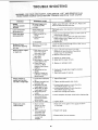
TROUBLE
SHOOTING
WARNING_ FOR IYOUR OWN SAFETY, TURN SWITCH "OFF" AND REMOVE PLUG
FROM POWER SOURCE OUTLET BEFORE TROUBLE SHOOTING YOUR SHAPER
"_-17
: _TROUBLE
J
PROBABLE
CAUSE
Set screw engaging
in spindle
too tight,
:itoo hard.
Cutter comes loose
:: during
operation.
Cutter slow down
I
during operation,
....Bindi.0fF "0e
......
i
Boards when adjusting
IN or
REMEDY
slot
Tighten screw then back it off 1/4 turn.
action is smooth without
end play.
assembly
Keyed washer not
properly installed.
The keyed
the nut.
washer must always
1. Work being fed too
rapidly.
2. Insufficient
belt
tension.
t. Feed work
thro'ugh
Adjust
be used directly
more slowly
to allow
3, Glazed belt
remove
2, Loosen
slightly
correct,
3. Replace
Bottoms of fence faces
striking table.
Loosen
s_ightly
1, Work piece not being
held firmly against
fence and/or table.
1, Apply sufficient
hand pressure in both
directions
or revise Auxiliary
Fence/Work
Support (pg. 15) accordingly.
2. Maintain continuous
feed,
until
under
cutter
to
stock smoothly,
motor mount plate bolts and move motor
toward rear of shaper until belt tension is
tighten bolts.
belt,
the two screws through
and tighten screws,
front
of face, raise it
out.
Shaper produces ragged
or riplMe cuts.
_.
2. Interrupted
:
feed
past cutter.
3. Dull cutter.
4, Belt slipping - causing
, cutter speed to vary.
5, Cutter blades not
concentric.
(Blade
,
3. Sharpen or replace cutter
4. Adjust [belt for proper tension.
5. Replace or resharpen
cutter,
segments have uneven
lengths.)
, :
.
:
:
:
:
'
F:
6. Feed work through
smooth cut,
6. Work being fed too
7_ Quality of wood not
sufficient
to produce
::: .... desired results,
7. Use a better
slow
enough
to produce
grade of material.
fence faces.
smooth
.,
not l'_|d
cut, but does
a straight edge,
:
set.
2: Spindie Assembly lock
knobnot
tight.
'
3. WOrkpiece not held
2. Tighten
assembly lock
knob.
3, increase hand pressure or revise Auxiliary
Fence/Work
Support
(10g, 15).
4. Increase hand pressure or revise Auxiliary
Fence/Work
Support (pg. t 5),
snugly against fence.
4. Work piece not held
snugly against table.
5, Work being fed to
rapidly.
Shape varies across
.width of board.
spindle
5. Feed work
through
6. Attempting
to remove
more material than
required to produce
desired shape.
7. Fence loose on table.
6, Joint workpiece
1. Work not held
securely to miter
gauge and/or to
table.
2. End of workpiece
not Paraltel with
miter gauQe slot.
3, End to be shaped
is wavy (not
straight),
1. Hold work firmly
on the table,
7, Tighten
2. Adjust
I
2O
more
to proper
slowly,
width
before
shaping
fence.
miter
3. Resaw andlor
against
miter
gauge.
joint as necessary.
gauge and down
edge.
TROUBLE
SHOOTING
-- MOTOR
NOTE: Motors used on wood-working
tools are particularly
susceptible to the accumulation
of sawdust and wood chips and should be blown out or "vacuumed"
frequently
to prevent
interference
with normal
motor ventilation.
TROUBLE
.......
PROBABLE
REMEDY
CAUSE
,,,,_ ...................
Excessive
1. Motor.
noise.
t. Have motor checked
by qualified
service
techniciar_.
Repair service _s available
at
your nearest Sears store.
overloaded
1 Circuit
tights, appliances
other motors
Motor fails to develop
full power. NOTE:
LOW VOLTAGE:
(Power
output
of motor
decreases
rapidty
with
decrease
m voltage at
motor terminals
For
2 Undersize
too long.
exampte,
a reduction
of
10% in voltage causes
a reduction
of 19% m
maximum
power output
of which the motor Is
wires
with
and
t. Do not use other appliances
or motors
same circuit
when using U"te saw
or c_rcuit
3, General
over}oadmg
power company
facilities.
on
2. increase
wire sizes, or reduce
!er_gth of w_r}ng
See "Motor
Specifications
arqd Etectrtca!
Requirements"
sechon
of
3. Request
company
a voltage
I
Request
vottage
2
Have motor
3
Have relay
check
from
the power
capabIe,
and a reduction
of 20% in voltage causes
a reduction
of 36% m
maximum
power output.)
............
i,,
, ,
,,
1, Low voitage
trip relay
Motor starts slowly
or fails to come up
to full speed,
2 Wir_dings
wiU not
burned
out
check
repaired
from the power
company
or replaced
or opera.
3, Start{ng
ope, fat*r;g
Motor
relay
not
.................
1 Feed
1 Motor overloaded
2, Improper
cooftng.
(Air
circulation
restricted
overheats.
operate.
,,_
, ......
slower
into blade.
to provide
normal air
motor.
and Lubrication"
section.
'i'["Havd switch reP'i'acedan'd req"uesi'a'"v'o_tage
check
1. Bu rned "sw"i"tCh contacts
(due to extended
hold-in
periods caused
by [ow line voitage, etc.)
2. Shorted
capacitor
3. Loose or broken
connecttons
in
work
2. C_ean out sawdust
circulation
through
See "Maintenance
through
motor due to
sawdust,
accumulating
inside of saw).
Starting switch
motor will not
rep{aced
from
the
power
company.
2 Have capacitor
tested and replace
3. Have wiring checked
and repaired
_f defechve
, ,,
Motor stalls
(resufting
in blown
fuses or tripped
circuit
breakers),
1 Starting
switch
operating.
1 Have switch
not
2 Request
2 Voltage
too low to permit
motor tO reach operating
speed.
breakers
3. Fuses or circuit
do not have sufficient
3. install
replaced
voltage
proper
check
from
s_ze fuses
the power
or c_rcuit
company
breakers
capac,ty.
, ........
Frequent opening
fuses or circuit
breakers.
®
of
,....
1 Feed
!. Motor overloaded.
2. Fuses or c_rcuit breakers
do not have sufficient
2. ]nstatl
work
slower
proper
into
s_ze fuses
capacity
3
Starting
swdch not
operating
(motor does
not reach speed}
21
Have sw_tch
replaced
btade
or c_rcu_t breakers
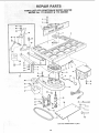
R:::E
PAl R::iP ART S
I
\
\
6
22
PARTS
LIST FOR CRAFTSMAN
MODEL
No. 113.239201
Always
Order
by Part
No.
- Not
FIGURE
"°Yi
No.
1
2
3
4
5
6
7
8
9
10
11
12
13
14
15
16
17
18
19
2O
21
22
23
24
25
26
Part
No.
72008
60167
STD 523120
39411
39613
C39290
39512
STD 551037
STD 541137
39629
STD551031
38799
39628
38546
60382
STD 551210
STD 51 t 105
39215
72014
STD 304330
STD 53311 2
STD 551031
STD 541231
39217
453068
WOOD
SHAPER
& 113.239390
by Key
1
'
Key
j No.
Description
Fence Assembly
(See Figure 2)
Washer, .343 x 1.062 x 1/8
*Screw, Hex Hd. 5/16-18 x 2
tnsert, Table
Pin, Table Dowel
Table (includes
Nameplate)
Knob, Lock
*Washer, 13/32 x 47/64 x 1/t6
*Nut, Hex. Jam, 3/8-24
Stud, Lock
*Washer, 2t/64 x 7/8 x t/8
Screw, Set, 3/8-24 x 3/4 Dog Pt.
Rod, Elevating
Knob
Switch Box Assembly
(See Figure
*Lockwasher,
Internal
No. 10
*Screw, Pan Hd. 10-32 x t/2
Base
Spindle Assembly
Plate, Guard
_Belt, V, 1/2 x 33
*Bolt, Carriage
*Washer 21/64
(See Figure
5/16-18
[
5)
x 1-1/4
Hardware
Part
No.
Description
'
72003
STD 503102
Guard,
i * Screw,
Soc.
Puiiey,
i'Washer,
39230
STD 55t037
42
43
44
45
46
47
56634
72026
72023
68036
37435
37837
38713
72022
Pulley
Set 5/t6-18
x 5/!6,
Hd. Cup Pt.
Motor, (w/Set Screw)
25/64 ×!-9/64
x 7/64
STD 523710i*Screw,
Hex Hd. 3/8-16 x 1
39216
i Support
Table
72027
i Guard,
Asm. Cutter
72024
i Support
Assembly,
R.H.
72025
I Support
Assembly,
L.H.
STD 55t 23! * Lockwas=her,
tnternal 5/16
STD 523t 12 Screw, Hex Hd. 5/16 x 18x
72005
Guard,
Cutter
60262
Grip
STD 541525 *Nut,
Lock t/4-28
70001
Hub Asm. Lock
172036
Items - May be Purchased
23
t
i
L.........
29
30
3t
32
33
34
35
36
37
38
39
40
41
48
*Nut, Hex 5/1618
Mount,
Motor
Screw, Mach, 5/16-18 x 3/4,
Hex, Hd. wiLockwasher
*Standard
27
28
4)
Number
Locaily.
1-1/4
Includes
Key No. 39)
Stud, Nut
Arm, Guard
Holder,
Guard
Hanger,
l'Wrench,
t Wrench,
Cabte
Hex.,
Hex.,
t/4
5,32
Wrench
Bag Asm. Loose Parts
(not illustrated)
i Owners
Manuat
(not illustrated)
PARTS LIST FOR CRAFTSMAN
WOOD SHAPER
MODEL No. 113;239201
& 113.239390
!
2
1
6
7
9
\
11
/ IOi
11
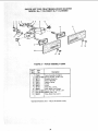
FIGURE 2 - FENCE ASSEMBLY 72008
Part
i.:
Description
,
L
72008
: Fence Assembly Complete
STD 511t005 *Screw, Pan Hd., t0-24 x 1/2
2
38711
" Bracket, Retaining
••••••i•3¸ 386!2
Knob, Adjusting
•: _•4 • •• : 18451
Washer; Spring
38413.
Frame
38531
Knob
_"i_'__i 6 "/ i 38 i10
Shoe Assy., Fence
_
_9
38533
Plate, Work Face (Right)
t0
STD 512507 *Screw, Pan Hd., 1/4.20 x 3/4
11
STD 551012 *Washer, Plain, 1/4
12
38532
Piate, Work Face (Left)
*Standard Hardware Item - May be Purchased Locally.
24
t0
PARTS LiST FOR CRAFTSMAN
WOOD SHAPER
MODEL No. 113.239201
& 113.239390
2
FIGURE 3 -- LEGS (Supplied with 113.239390
K 3y
No.
Part
No.
1 62614
2 60314
3 STD541025
4
5
6
7
10
11
STD551225
68060
72030
68059
62615
STD610805
STD 541050
803835
HARDWARE
w
Description
Leg
oScrew, Truss Hd. I/4-20 x 5/8
e'Nut, Hex 1/4-20
e* Lockwasher, 1/4 External
Channel, Support
Stiffener
Stiffener, Side
Stiffener, End
e'Screw, Pan Hal. Ty. A N8 x 1/2
o'Nut, Hex Hd. 1/2-13
e Foot, Leveling
FOR MOUNTING
STD523130
STD551131
STD541231
STD551031
only)
Standard
locally.
Hardware
Item
-
May be purchased
Stock Item - May be secured through
the
Hardware
Department
of most Sears Retail
Stores or Catalog Order Houses,
TOOL
These parts contained
No. 72031.
e Screw, Hex Hd. 5/!6-t8 x 3
e* Lockwasher, 5/16 External
*NUt, Hex Jam 5/16-18
*Washer, 11/32 ID
25
in Loose Parts Bag
PARTS LIST FOR CRAFTSMAN
:_MODEL No. 1113,239201:&
WOOD SHAPER
113.239390
7
8
6
/
/
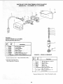
FIGURE 4 ON/OFF POWER OUTLET 60382
AND MOUNTING
BRACKET
i Key
No,
•
Part
No.
i
JL LL L
,
Descriptionii
"i
60382
o 0n/Off
i
2
60375
60378
Cord, Molded
Housing; Switch
Power Outlet
.....
31
4
7
5
6
7
Screw;
448007
'; 72034
STD600803
*Standard
Pan Hd. No. 6 x 3/4
Bracket, Switch MoUnting
i'Screw,
Pan Hd: Plastite No, 8x
Hardware
• Does Not Include
Order Separately
Item
-- May be Purchased
FIGURE 5-
3/8
Locally.
Key
No.
Key No. 3
If Required.
SPINDLE
Part
No.
Description
......
-1
2
3
4
5
6
396! 5
39711
39616
39617
72007
STD 503103
STD 328011
*Standard
/i:•_:••_/=•
¸_!ii!¸• •••
ASSEMBLY
• •
_/_ii//iiii_i_i
iiiiiiiiii:i_!i_i
_iii_
!_iii!Ii __i_
_III
_i i_ _ i
26
Hardware
rl
i,
Spindle Assembly Complete
Nut, Spindle
Washer, Keyed
Spacer 1/4
Spacer 7/16
Spindle Assembly
*Screw, Set 5/16-18 x 3/8,
Soc. Hd. Cup pt.
*Pultey, (w/Set Screw)
2x 1/2 Bore
Item
-
"V'"
May be Purchased
Locally.
PARTS LIST FOR CRAFTSMAN
WOOD SHAPER
MODEL No. 113.239201
& 113.239390
NOTE:
ANY ATTEMPT
TO REPAIR
THIS
MOTOR
MAY CREATE
A HAZARD
UNLESS
REPAIR
IS DONE
BY QUALIFIED
SERVICE
TECHNICIAN,
REPAIR
SERVICE
IS AVAILABLE
AT YOUR
NEAREST
SEARS
STORE,
1
2
FIGURE 6 -- 72035
Part
No.
Key
No.
3
MOTOR
1
60306
2
3
64088
64258
PARTS LIST
Description
Screw, 8-32 x 3/8, Thread
Cutting,
Stotted,
Serrated
Hd.
Cover, Terminal
Cord with Plug
TERMINAL
MOTOR
GREEN
CONNECTIONS
WARNING:
FOR
YOUR
OWN
SAFETY,
NEVER
CONNECT
PLUG TO POWER
SOURCE
OUTLET UNTIL
ALL ASSEMBLY
STEPS ARE COMPLETED.
1. Open motor connector
motor (viewed
from
screwdriver.
_NTERNAL\
LOCKWASHER
box cover tocated on ]eft end of
rear of saw) using a flat blade
_'
"_
1
BLACK WIRE TO
TERMINAL T1
2. Remove GREEN
SCREW and Iockwasher
and insert
screw through
round metal terminal
on the end of the
GREEN wire of power cord with Iockwasher
between
terminal and motor frame. (See illus.)
3. Reinsert
securely.
GREEN
SCREW
in the threaded
hole. Tighten
GREEN WIRE
GF_EEN SCREW
4. Insert terminal
end of WHITE wire on spade terminal
marked
T4 on the motor. Push terminal
firmly
until
seated.
5. Insert terminal
end
marked
T1 on the
seated.
STRAIN RELIEF
PVE
WIRE TO
T4
of BLACK wire on spade terminal
motor. Push terminal
firmly
until
6. Close motor connector
box being sure that power cord is
seated in the largest strain relief groove, and tighten box
cover screws.
27
WOOD
SERVICE
Now
ever
[h_._[ you
exist
Service,
Center
to provide
MODEL NO.
113.239201
SHAPER
for
SHAPER
have
purch_}sed
repair
parts
m_d most
aI! perti_ent
]"he model number
of
ptate attached
to your
your
or
Sears,
facts
wood
service,
Roebuck
when
Vou
shaper,
simply
and
call
should
contact
Co,
a need
arW
stores.
Sears
Be sure
or visit,
your wood shaper will be found
on a
wood shaper on the front of the tab}e,
ONLY
113.239390
SHAPER
WITH STEEL
LEGS AND MOTOR
HOW TO ORDER
WHEN
ORDERING
REPAIR
FOLLOWtN3
INFORMATION:
PARTS,
ALWAYS
GIVE
THE
REPARR PARTS
PART
NUMBER
MODEL NUMBER
113.239201
1 ! 3.239390
PART DESCRIPTION
NAME OF ITEM
WOOD SHAPER
A!I parts listed may be ordered
from any Sears Service Center
and most S_ars stores, tf the parts you need are not stocked
locally,
your order will be electronically
transmitted
to a Sears
Repair Parts Distributior_
Center for handling,
Sold
Part No, 72036
by SEARS,
ROEBUCK
AND
CO.,
Form No, SP4926-2
Chicago,
IlL. 60684
U.S.A.
Printed in U.S.A_ 6/89