1
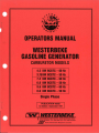
OPERATORS MANUAL
WESTERBEKE
GASOLINE GENERATOR
CARBURETOR MODELS
4.5 KW
3.75KW
7.2 KW
6.0 KW
9.6 KW
8.0 KW
BCGTC
BCGTC
BCGTC
BCGTC
BCGTC
BCGTC
-
60
50
60
50
60
50
Hz
Hz
Hz
Hz
Hz
Hz
Single Phase
•
PUBUCATION 42832
I
1st Edition / September 1997
~
WESJ'ERBEKE
WESTERBEKE CORPORATION · AVON INDUSTRIAL PARK
AVON, MA 02322 • TEL: (SOB) 588-7700 · FAX: (SOB) 559-9323
~~.,"""
~M'A
M~mber Naiio1l41 Morine Mo.twfoctu~rsASS()CiD.tion
Gasoline with an ETHANOL content
higher than 10% (E10) is not allowed
and may void warranty.
Engines & Generators
SAFETY INSTRUCTIONS
INTRODUCTION
PREVENT BURNS - FIRE
Read this SIlfety manu4l carefully. Most accidents are caused
by faiLure w follow fundamenwL rules and precautions.
Know when dangerous conditions exist and wke the
necessary precautions to protect yourse/}; your personnel,
and your machinery.
The following SIlfety instructUms are in compliance with
the A merican Boat and Yacht Council (ABYC) swndards.
PREVENT ELECTRIC SHOCK
A WARNING: Do not touch AC electrical connections
while engine is ronning, or when connected to shore
power. Lethal voltage is present at these connections!
A WARNING:
Fire can cause injury or death!
• Prevent flash fires. 00 not smoke or permit flames or
sparks to occur near the carburetor, fuel line, filter, fuel
pump, or other potential sources of spill ed fuel or fuel
vapors. Use a suitable container to catch all fuel when
removing the fuel line; carburetor, or fuel filters.
• 00 not operate with a Coast Guard Approved flame
arrester removed. Backfire can cause severe injury or
death.
• Do not operate with the air cleaner/silencer removed.
Bac'kfire can cause severe injury or death.
• Do not smoke or pennit flames or sparks to occur ncar the
fuel system. Keep the compartment and the engi ne/gener·
ator clean and free of debris to minimize the chances of
fire. Wipe up all spilled fuel and engine oil.
• Do not operate this machinery without electrical
enclosures and covers in place.
• Shut off electrical power before accessing electrical
equipment.
• Be aware -
• Use insul ated mats whenever working o n electrical
equipment.
PREVENT BURNS - EXPLOSION
•
Make sure your clothing and skin are dry, not damp
(particularly shoes) when handling electrical equipment.
•
Remove wristwatch and all jewelry when working o n
electrical equipment.
Electrical shock results from handling a charged capacitor.
Discharge capacitor by shorting terminals together.
PREVENT BURNS - HOT ENGINE
A
WARNING: 00 not touch hot engine parts or
exhaust system components. A ronning engine gets
very hot!
•
Explosions from fuel vapors can cause
• Follow re-fueling safety instructions. Keep the vessel 's
hatches closed when fueling. Open and ventilate cabin
after fueling. Check below for fumes/vapor before running
the blower. Run the blower for four minutes before starting your engine.
• All fuel vapors are highly explosive. Use extreme care when
handling and storing fuels. Store fuel in a well·ventilated
area away from spark-producing equipment and o ut of the
reach of children.
• 00 not fill the fuel tank(s) while the engine is running.
• Shut off the fuel service valve at the engine when servici ng
the fuel system. Take care in catching any fuel that might
spill. DO NOT allow any smoking, open flames, or ot her
sources of fire near the fuel system or engine when servicing.
Ensure proper ventil ation exists when servicing the fuel
system.
• Always check the engine coolant level at the coolant
recovery tank.
A WARNING:
A WARNING:
injury or death!
• 00 not connect util ity shore power to vessel's AC
circuits, except through a ship-la-shore double throw
transfer switch. Damage to vessel's AC generator may
result if this procedure is not followed.
•
diesel fuel will bum.
• 00 not alter or modify the fuel system.
Steam can cause injury or death!
• Be sure all fuel supplies have a positive shutoff valve.
In case of an engine overheat, allow the engine to cool
before to uching the engine or checking the coolant.
• Be certain fuel line fittings are adequately tightened and
free of leaks.
• Make sure a fire extinguisher is installed nearby and is
properly maintained. Be familiar with its proper use.
Extinguishers rated ABC by the NFPA are appropriate
for all applications encountered in this environment.
Engines & Generators
SAFETY INSTRUCTIONS
ACCIDENTAL STARTING
A
TOXIC EXHAUST GASES
A
WARNING: Accidental starting can cause injury
WARNING:
Cari10n monoxide (CO) is a deadly gas!
Dr death!
• Ensure that the exhaust system is adequate to expel gases
discharged from the engine. Check the exhaust system
regularly for leaks and make sure the exhaust manifolds
are securely attached and no warping exists. Pay close
attention to the manifold, water injection elbow, and
exhaust pipe nipple.
• Disconnect the battery cables before servicing the engine/
generator. Remove the negative lead first and reconnect
it last.
• Make certain all personnel are clear of the engine before
starting.
• Make certain all covers, guards, and hatches are
installed before starting the engine.
• Be sure the unit and its surroundings are well ventilated.
re~
• In addition to routine inspection of the exhaust system,
install a carbon monoxide detector. Consult your boat
builder or dealer for installation of approved detectors.
BATTERY EXPLOSION
A
•
WARNING:
Battery explosion can cause injury
Dr death!
A
WARNING:
Cari10n monoxide (CO) is an invisible
odorless gas_ Inhalation produces flu-like symptoms,
nausea Dr death!
• Do not smoke or allow an open flame near the battery
being serviced. Lead acid batteries emit hydrogen, a
highly explosive gas, which can be ignited by electrical
arcing or by lit tobacco products. Shut off all electrical
equipment in the vicinity to prevent electrical arcing during
servicing.
•
For addi tional information refer to ABYC T-22 (educational information on Carbon Monoxide).
• Do not use copper tubing in diesel exhaust systems. Diesel
fumes can rapidly destroy copper tubing in exhaust systems. Exhaust sulfur causes rapid deterioration of copper
tubing resulting in exhausVwater leakage.
Never connect the negative (-) battery cable to the positive (+) connection lenninal of the starter solenoid. Do not
test the battery condition by shorting the terminals
together. Sparks could ignite battery gases or fuel vapors.
Venti late any compartment containing batteries to prevent
accumulation of explosive gases. To avoid sparks, do not
disturb the battery charger connections while the battery is
being charged.
• Do not install exhaust outlet where exhaust can be drawn
through portholes, vents, or air conditione~. If the engine
exhaust discharge outlet is near the waterline, water could
enler the exhaust discharge outlet and close or restrict the
flow of exhaust. Avoid overloading the craft.
• AJthough diesel engine exhaust gases are not as toxic as
exhaust fumes from gasoline engines, carbon monoxide
gas is present in diesel exhaust fumes. Some of the symptoms or signs of carbon monoxide inhalation or poisoning
• Avoid contacting the leoninals with tools, etc.! to prevent
burns or sparks that could cause an explosion. Remove
wristwatch, rings, and any other jewelry before handling
the battery.
are:
Vomiting
• Always tum the battery charger off before disconnecting
the battery connections. Remove the negative lead first
and reconnect it last when servicing the battery.
Dizziness
Throbbing in temples
Muscular twitching
BATTERY ACID
Intense headache
A
Weakness and sleepiness
WARNING:
Sulphuric acid in batteries can cause
severe injury or death!
AVOID MOVING PARTS
• When servicing the battery or checking the electrolyte
level, wear rubber gloves, a rubber apron, and eye protection. Batteries contain sulfuric acid which is destructive. If
it comes In contact with your skin, wash it off at once
with water. Acid may splash on the skin or into the eyes
inadvertently when removing electrolyte caps.
~
A WARNING: Rotating parts can cause injury
or death!
• Do not service the engine/generator while it is running. If a
situation arises in which it is absolutely necessary to make
WESTERBEKE
Engines & Generators
ii
SAFETYINSTRUCT10NS
ABYC, NFPA AND USCG PUBLlCAnONS FOR
INSTAWNG GASOUNE AND DIESEL ENGINES AND
GENERATORS
operating adjustments, use extreme care to avoid touching
moving parts and hot exhaust system components.
• Do not wear loose clothing or jewelry when servicing
equipment; avoid wearing loose jackets, shirts, sleeves,
rings, necklaces or bracelets that could be caught in
moving parts.
Read the following ABYC, NFPA and USCG publications
for safety codes and standards. Follow their recommendations when installing your WESTERBEKE engine/generator.
• Make sure all allaching hardware is properly tightened.
Keep protective shields and guards in their respective
places at all times.
ABYC (American Boat and Yacht Council)
"Safety Standards for Small Craft"
Order From:
ABYC
15 East 26th ~treet
New York, NY 10010
• Do not check fluid levels or the drive belts' tension while
the engine/generator is operating.
• Stay clear of the drive shaft and the transmission coupling
when the engine is running; hair and clothing can easily
be caught in these rotating parts.
NFPA (National Fire Protection Association)
"Fire Protection Standard for Motor Craft"
HAZARDOUS NOISE
A
Order From:
NFPA
1 Ballerymarch Park
P.O. Box 9101
Quincy, MA 02269-9101
WARNING: High noise levels can cause healing
loss!
•
Never operate a generator without
USCG (United States Coast Guard)
"USCG 33CFR183"
its muffler installed.
• Do not run an engine with the air intake (silencer)
removed.
Order From:
U.S. Government Printing Office
Washington, D.C. 20404
• Do not run engines or generators for long periods with
their enclosures open.
A
WARNING: Do not work on machinery when you
ale mentally 01 physically incapacitated by fatigue!
OPERATORS MANUAL
Many of the preceding safety tips and warnings are repeated
in your Operators Manual along with other cautions and
notes to highlight critical information. Read your manual
carefully, maintain your equipment, and follow all safety
procedures.
GASOLINE ENGINE AND GENERATOR
INSTALLATIONS
Preparations to install a gasoline engine or generator should
begin with a thorough examination of the American Boat and
Yacht Council's (ABYC) standards. These standards are from
a combination of sources including the USCG and the NFPA.
Sections of the ABYC standards of particular interest are:
H-2 Ventilation
H-24 Gasoline fuel systems
P -1 Exhaust systems
P4 Inboard engines
E-9 DC Electrical systems
All installations must comply with the Federal Code of
Regulations (FCR).
Engines & Generators
iii
r
•
INSTALLATION
When installing WESTERBEKE engines and generators it is imponant th at strict
attention be paid to the following infonnation:
CODES AND REGULATIONS
Strict federal regulations. ABYC guidelines. and safety codes must be complied with
when installing engines and generators in a marine environment.
SIPHON·BREAK
For installations where the exhaust manifold/water injected exhaust elbow is close to
or below the vessel's waterline, provisions must be made to install a siphon-break in
the raw water supply hose to the exhaust elbow. This hose must be looped a minimum
of IS" above the vessel's waterline. Failure to use a siphon-break when th e exhaust
numifold injection port is at or below the load waterline will result in raw waLer
damage to the engine and possible flooding of the boaL
EXHAUST SYSTEM
The exhaust hose must be certified for marine use. The system must be designed to
prevent water from entering the exhaust under any sea conditions and at any angle
of the vessels hull.
A detailed 40 page Marine Installation Manual covering gasoline and
diesel, engines and generators, is available from your WESTERBEKE
dealer.
~
WESTERBEKE
Engines & Generators
iv
WESJERBEKE
-.v'
Engines & Generators
Declaration of Conformity
Application of Council Directive(s)
EMC 89/336IEEC
ISO 8846 1990(E)
Standard(s) to Which Conformity
is declared
EN50081-1
EN50082-2
EN55020
ISO-8846-1990(E), Certification
Number, IWES003
Manufacturers Name
Westerbeke Corporation
Manufacturers Address
41 Ledin Drive
Avon Industrial Park
Avon, Ma. 02322, USA
Type of Equipment
Marine Gasoline Generator
Product Name
Westerbeke Marine
Gasoline Generator
Model(s)
3.7/4.5BCGTE,6.017.2BCGTE
8.0/9.6BCGTE,3.7/4.5BCGTC,
6.017.2BCGTC & 8.0/9.6BTGTC
Product Options
All
Supplementary Information
1.) The equipment listed is only for use in Marine Applications aboard boats.
2.) The equipment listed must be located below decks on the vessel and
permanently installed in it's location.
3.) The equipment listed must be wired to the grounding system of the vessel.
I the undersigned, hereby declare that the equipment specified above conforms to
the above Directive(s) and Standard(s).
Place Avon. Massachusetts, U.S.A.
Date: September 1, 1996
Carleton F. Bryant
(Full Name)
Chief Operating Officer
(Title)
WESTERBEKE CORPORATION, AVON INDUSTRIAL PARK, AVON, MA 02322 U.S.A .•TEL.(508) 588-7700 .FAX: (508) 559-9323_ WEBSITE:WWWWESTEABEKE.COM
INTERNATIONAL MARINE CERTIFICATION INSTITUTE
Treves Centre, Rue de Treves 45
B-1040 8RUXELLES
BELGIQUE
tel: +32 (0) 2-238-7892
fax: +32 (0) 2-238-7700
eEl? TIFICA TE
We hereby certify the component stated below meets the EC Directive 94J25/EC for
type-examination in accordance with ISO 8846 and has following characteristics:
ITYPE
MANUFACTURER
ADDRESS
I
IGROUP OF
Model 1
Model 2
I
Model 3
Model 4
Model 5
Model 6
Model 7
Model 8
Model 9
Model 1 0
Model 11
Model 12
Model 13
Model 14
Model 15
Model 16
Model 17
Model 18
Model 19
Model 20
Model 21
Model 22
Model 23
Certification number
Signed
Name
Title
EU Notified Body No
Date
Gasoline Marine Generator
Westerbeke Corp.
Avon Industrial Park,
Avon, MA 02333
USA
+++++
3.7/4.5 BCGTE
6.017.2 BCGTE
80/96 BCGTE
3.7/4.5 BCGTC
60/7.2 BCGTC
80/9.6 BCGTC
+++++
+++++
+++++
+++++
+++++
+++++
+++++
+++++
+++++
+++++
+++++
+++++
+++++
+++++
+++++
+++++
+++++
I
+++++
+++++
+++++
+++++
+++++
+++++
+++++
+++++
+++++
+++++
+++++
+++++
+++++
+++++
+++++
+++++
+++++
+++++
+++++
+++++
+++++
+++++
+++++
+++++
I
I
+++++
+++++
+++++
+++++
+++++
+++++
+++++
+++++
+++++
+++++
+++++
+++++
+++++
+++++
+++++
+++++
+++++
+++++
+++++
+++++
+++++
+++++
+++++
+++++
IWES003
? -,\:::://r <'-~-,
Lars E. 8r'§nholm
Managing Director
0609
..(.c'/h
02/0211998
/
I
TABLE OF CONTENTS
Introduction .......................................................................2
Engine Lubricating 0i1 ................................................... 16
Warranty Procedures ....................................................2
Description ................................................................. 16
Changing the Engine Oil... ......................................... 16
Replacing the Oil Filter. ............................................. 16
Refilling the Oil Sump ............................................... 16
Remote Oil Filter (Optionalj .......................................... 17
Installation .................................................................. 17
DC Electrical System .....................................................18
12-Volt DC Control Circuit. ...................................... .18
Batteries ...................................................................... 18
Customer Identification Card ....................................... 2
Product Software ......................................................... .2
Serial Number Location ............................................... 2
Ordering Parts ............................................................. .3
Notes, Cautions and Warnings ..................................... 3
Protecting Your Investment ......................................... .3
Spares and Accessories ............................................... .3
Control Panels ..................................................................4
Generator Panel ............................................................ 4
Remote Panel .............................................................. .4
Overspeed Circuit Board ............................................. .4
Specifications ...................................................... 18
Battery Maintenance ........................................... 18
Battery Charging ........................................................ 18
Component Testing .................................................... 18
Safety Shutdown Switches .............................................5
Safety Shutdown Switches .......................................... .5
High Exhaust Temperature Switch ...................... .5
High Water Temperature Switch .......................... .5
Low Oil Pressure Switch ..................................... .5
Engine Circuit Breaker ........................................ .5
Fuel, Engine Oil and Engine Coolant ............................6
Wiring Diagram #42834 ............................................. 19
Wiring Schematic #42834 ......................................... .20
Wiring Diagram #42857 Remote Panel(s) ................ .21
Engine Adjustments .......................................................22
Engine Speed (Hertz) Adjustment... ........................... 22
Governor ............................................................. 22
Governor Adjustments ........................................ 22
Governor Maintenance ....................................... .22
Torquing the Cylinder Head Bolts ............................. 22
Valve Clearance Adjustment ...................................... 22
Choke Solenoid .......................................................... 23
Ignition Timing .......................................................... .23
Spark Plugs ................................................................. 23
Carburetor Adjustment .............................................. .24
Drive Belts Adjustment ............................................. .24
Timing Belt Inspection and Replacement ................. .25
Engine Troubleshooting .................................................29
Generator Information ...................................................31
Use of Electric Motors .............................................. .31
Required Operating Speed ........................................ .31
Generator Frequency Adjustment .............................. 31
Generator Maintenance .............................................. 31
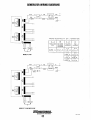
Generator Wiring Diagrams ..........................................32
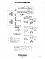
AC Electrical Connections ...........................................33
Lay-Up & Recommissioning ..........................................34
General ....................................................................... 34
Fresh Water Cooling System ......................................34
Lubrication System ................................................... .34
Fuel System ............................................................... .34
Raw Water Circuit ...................................................... 34
Intake Manifold ......................................................... .35
Starter Motor ............................................................. .35
Cylinder Lubrication ................................................ .35
Spare Parts ................................................................. .35
Batteries ..................................................................... .35
Recommissioning ....................................................... 35
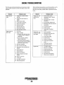
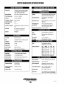
BCGTC Generator Specifications ................................36
BCGTC Generator Parts Identification ...................... .37
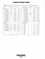
Standard Hardware Torques .........................................38
BCGTC Generator Hardware Torques ......................... .39
Metric Conversions ........................................................40
Suggested Spare Parts ..................................................41
Gasoline ........................................................................ 6
Care of the Fuel Supply ............................................... 6
Engine Oil .................................................................... 6
Engine Coolant ............................................................. 6
Coolant Recovery Tank ................................................ 6
Preparations for Initial Start-Up ................................... 7
Prestart Inspection ...................................................... _, 7
Operating Instructions .....................................................8
Generator Panel ............................................................ 8
Starting the Generator ........................................... 8
Stopping the Generator ......................................... 8
Remote Panel ............................................................... 8
Starting the Generator ........................................... 8
Stopping the Generator ......................................... 8
Emergency .stopping .................................................... 8
Starting Under Cold Conditions ................................... 8
Abnormal Stop .............................................................8
Break-In Procedure/Daily Operation .............................9
Break-In Procedure ...................................................... 9
Check List .................................................................... 9
Stopping the Generator ................................................ 9
Generator Adjustments ................................................. 9
Maintenance Schedule ..................................................10
Engine Cooling Circuit.. .................................................12
Description ................................................................. 12
Thermostat .................................................................. 13
Thermostat Test .......................................................... 13
Draining the Coolant .................................................. 13
Refilling the Coolant .................................................. 13
Raw Water Pump ........................................................ 14
Changing the Raw Water Pump Impeller .................. 14
Heat Exchanger .......................................................... 14
Drive Belt Adjustment .............................................. .14
Fuel System .....................................................................15
Gasoline ..................................................................... .15
Carburetor .................................................................. .15
Gasoline/Water Separator and Filter .......................... 15
Fuel Pump .................................................................. 15
Gasdenser ................................................................... 15
Engines & Generators
1
INTRODUCTION
WESTERBEKE CANNOT BE RESPONSIBLE FOR THE CONTENT
OF SUCH SOFTWARE, MAKES NO WARRANTIES OR REPRE·
SENTATIONS WITH RESPECT THERETO, INCLUDING ACCU·
RACY, TIMELINESS OR COMPLETENESS THEREOF AND Will
IN NO EVENT BE LIABLE FOR ANY TYPE OF DAMAGE OR
INJURY INCURRED IN CONNECTION WITH OR ARISING OUT OF
THE FURNISHING OR USE OF SUCH SOFTWARE.
This WESTERBEKE Generator is a product of
WESTERBEKE'S long years of experience and advanced
technology. We take great pride in the superior durability and
dependable perfonnance of our engines and generators.
Thank you for selecting WESTERBEKE.
In order to get the full use and benefit from your generator,
it is important that you operate and maintain it correctly. This
manual is designed to help you do this. Please read this
manual carefully and observe all the safety precautions
throughout. Should your engine require servicing, contact
your nearest WESTERBEKE dealer for assistance.
WESTERBEKE customers should also keep in mind the time
span between printings of WESTERBEKE product software
and the unavoidable existence of earlier WESTERBEKE
manuals. In summation, product software provided with
WESTERBEKE products, whether from WESTERBEKE or
other suppliers, must not and cannot be relied upon exclusively as the definitive authority on the respective product. It
not only makes good sense but is imperative that appropriate
representatives of WESTERBEKE or the supplier in question
be consulted to determine the accuracy and currentness of the
product software being consulted by the customer.
This is your Operators Manual. A Parts Catalog is also
provided and a Technical Manual is available from your
WESTERBEKE dealer. Also, if you are planning to install
this equipment yourself, contact your WESTERBEKE dealer
for WESTERBEKE'S Installation Manual.
WARRANTY PROCEDURES
Your WESTERBEKE Warranty is included in a separate
folder. If you have not received a customer identification
card registering your warranty 60 days after submitting the
warranty registration form, please contact the factory in
writing with model information, including the unit's serial
number and commission date.
I~l
SERIAL NUMBER LOCATION
The generator serial number and model number is located on
a decal on the the generator housing. Take the time to enter
the information on the blank decal provided. This will provide a quick reference when seeking technical information
and/or ordering parts.
WESTERBEKE
1 Marine Engine Pl'Oducts
Customer Identification
WESTERBEKE OWNER
MAIN STREET
HOMETOWN, USA
Model BCGTC Ser. #D703XXXX
Expires 9/20/02
CUSTOMER IDENTIFICATION CARD (Typical)
The WESTERBEKE serial number is an alphanumeric
number that can assist in determining the date of
manufacture of your WESTERBEKE engine/generator. The
first character indicates the decade (A=1960s, B=1970s,
C=1980s, D=1990s), the second character represents the year
in the decade, and the fourth and fifth number represents the
month of manufacture.
PRODUCT SOFTWARE
Product software (tech data, parts lists, manuals, brochures
and catalogs) provided from sourccs other than WESTERBEKE are not within WESTERBEKE'S CONTROL.
Engines & Generators
2
INTRODUCTION
The engine model number and serial number are located on a
plate mounted on the engine's valve cover.
PROTECTING YOUR INVESTMENT
Care at the factory during assembly and thorough testing
have resulted in a WESTERBEKE generator capable of
many thousands of hours of dependable service. However the
manufacturer cannot control how or where the generator is
installed in the vessel or the manner in which the unit is
operated and serviced in the field. This is up to the
buyer/owner-operator.
ORDERING PARTS
NOTE: Six important steps to ensure long generator life:
Whenever replacement parts are needed, always provide the
generator and engine model and serial numbers. In addition,
include a complete part description and part number for each
part needed (see the separately furnished Parts Catalog). Also
insist upon WESTERBEKE packaged parts because will fit
or generic parts are frequently not made to the same specifications as original equipment.
• Proper engine and generator installation and alignment.
• An efficient well-designed exhaust system that includes
an anti~siphon break to prevent water from entering the
engine.
• Changing the engine oil and oil fdters every ZOO operat.
ing hours.
• Proper maintenance of all engine and generator components according to the maintenance schedule in this
NOTES, CAUTIONS AND WARNINGS
As this manual takes you through the operating procedures,
manual.
maintenance schedules, and troubleshooting of your generator, critical information will be highlighted by NOTES,
CAUTIONS, and WARNINGS. An explanation follows:
• Use clean, filtered unleaded fuel.
• Winterize your engine according to the "Lay-up and
Recommissioning" section in this mnnual.
NOTE: An operating procedure essential to note.
SPARES AND ACCESSORIES
A
CAUTION: Procedures, which if not strictly
observed, can result in the damage or destruction of
the engine or generator.
A
Certain spare parts will be needed to support and maintain
your WESTERBEKE generator or engine when cruising (see
SUGGESTED SPARE PARTS). Often even simple items such
as proper fuel and oil filter can be difficult to obtain along
the way. WESTERBEKE will provide you with a suggested
spares and accessories brochure to assist you in preparing an
on-board inventory of the proper WESTERBEKE parts.
WARNING: Procedures, which if not properly
followed, can result in personal injury or loss of life.
Engines & Generators
3
CONTROL PANELS
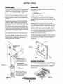
GENERATOR PANEL
REMOTE PANEL
The ON and START/OFF switches are the only functional
components to operate the generator at the engine. Both
switches are used to start the generator - see Starting the
Generator under OPERATING INSTRUCTIONS.
There are three functional components on the remote panel
for generator operation:
LON switch
2. START/STOP switch
The ON switch is a two-position switch with momentary
contacts in the up (on) position and a stationary contact
function in the center position. This switch energizes the
fuel pump.
3. Green LED indicator light
The ON switch is a two-position switch with momentary
contact functions in the up (Oil) position and a stationary contact function in the center position. This switch energizes the
fuel pump.
The START/OFF switch is a three-position switch with
momentary contact functions in the up (start) and down
(off) positions, and a stationary contact function in the
center position. When in the center (normal) position, this
switch allows the generator to be run, once started. When
in the up (start) position (together with the ON switch in
the up position), this switch starts the generator, and once
released, reverts to the center position. When in, the down
(off) position, this switch stops the engine in nonnal operation as well as in an emergency situation.
The START/STOP switch is a three-position switch with
momentary contact functions in the up (start) and down
(stop) positions, and a stationary contact function in the center position. The center position is a dual offJrun mode position and is normally in the off mode. When in the start (up)
position, this switch starts the generator (together with the
ON switchin the up position) and once released, reverts to
the center position, run mode. When in the stop (down) position, this switch stops the generator, and once released,
reverts to the center position, off mode.
When maintenance is being performed on the generator,
the 8 amp fuse should be removed. This will disable the
remote control panel(s), preventing attempts to start the
generator from their locations. However, it is always best
to disconnect the battery during this time jf it is not
required to perfonn the maintenance.
,
8 AMP FUSE: THE 8 AMP
FUSE ENERGIZES THE
. DC CIRCUIT
The Green LED indicator light indicates the engine running
condition. It lights when the ON switch is moved to the start
position, dims when the engine is cranking, and brightens
when the engine starts, notifying the operator to release the
START switch.
START/STOP
TOGGLE SWITCH
ON
REMOTE
PANEL
HOURMffiR: THE HOURMETER
RECORDS ELAPSED TIME OF ENGINE
USAGE. THE TOTAL NUMBER OF
HOURS SHOULD BE USED AS A GUIDE
FOR MAINTENANCE SCHEDULING.
OVERSPEED CIRCUIT BOARD
The overspeed circuit board senses the engine speed through
pulses off the engine coil. If the engine speed exceeds 3800
rpm, this overspeed circuit will activate, and will interrupt DC
power to the K2 relay shutting the engine down. It has an
automatic reset.
20 AMP CIRCUIT BREAKER:
THE 20 AMP RESET CIRCUIT BREAKER
PROTECTS THE ENGINE'S ELECTRICAL
SYSTEM FROM ELECTRICAL OVERLOADS.
START/OFF
TOGGLE SWlTCH
~-I+
TOGGLE
SWITCH
___ ON
TOGGLE SWITCH
CIRCUIT BREAKER: THE HEAVY
DUTY ON/OFF CIRCUIT BREAKER SHUTS
DOWN THE GENERATOR'S AC POWER.
NOTE: THIS CIRCUIT BREAKER SHOULD
BE IN THE OFF POSITION WHEN
PERFORMING MAINTENANCE.
GENERATOR
PANEl
a
~
WESTERBEKE
Engines & Generators
4
OVERSPEED
CIRCUIT BOARD
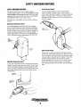
SAFETY SHUTDOWN SWITCHES
SAFETY SHUTDOWN SWITCHES
Low Oil Pressure Switch
The engine is protected by three automatic shutdown
switches. Should a shutdown occur, do not attempt to restart
without finding and correcting the cause. Refer to the heading Engine starts, runs and then shuts down in the ENGINE
TROUBLESHOOTING section of this manual.
A low oil pressure shutdown switch is located off the
engine's oil gallery. Normally open in a static state, this
switch's sensor monitors the engine's oil pressure. Should the
engine's oil pressure fall to 5-10 psi, this switch will open
interrupting the DC voltage to the K2-run relay thereby shutting off the engine.
The following is a description of these automatic shutdown
switches:
High Exhaust Temperature Switch
An exhaust temperature switch is located on the exhaust
elbow. Nonnally closed, this switch will open and interrupt
the DC voltage to the K2-run relay (shutting off the engine)
should the switch's sensor indicate an excessive exhaust temperature (an inadequate supply of raw water causes high
exhaust temperatures). This switch opens at 260-270°F (127132°C). This switch resets at approximately 225°F (107°C).
LOW OIL
PRESSURE SWITCH
HIGH
EXHAUST
TEMPERATURE
I
ELBOW
Engine Circuit Breaker
The generator's engine is protected by an engine mounted
manual reset circuit breaker (20 amps DC). Excessive current
draw or electrical overload anywhere in the instrument panel
wiring or engine wiring will cause the breaker to trip. In this
event the generator will shut down because the opened
breaker interrupts the DC circuit to the K2-run relay. If this
should occur, check and repair the source of the problem.
After repairing the fault, reset the breaker and restart the generator.
High Water Temperature Switch
A high water temperature switch is located at the thermostat
housing. Nonnally closed, this switch, should the fresh water
coolant's operating temperature reach approximately 210°F
(99°C), will open and interrupt the DC voltage to the K2-run
relay thereby shutting off the engine. This switch resets at
195°F (107°C).
THERMOSTAT
HDUS!NG-_ _ _ .1
HIGH WATER
TEMPERATURE
SWITCH
/
Engines & Generators
5
FUEL, ENGINE OIL AND ENGINE COOLANT
GASOLINE
ENGINE COOLANT
Westerbeke recommends a mixture of 50% antifreeze and
50% distilled water, when possible. Distilled water is free
from the chemicals that can corrode internal engine surt'aces.
A
CAUTION: Only use unleaded fuel with an octane
rating of 89 or higher. Leaded fuel will cause serious
hann to your engine and violate your warranty.
The antifreeze petfonns double duty, as it allows the engine
to run at proper temperatures by transferring heat away from
the engine to the coolant. It also lubricates and protects the
cooling circuit from rust and corrosion. Use a good quality
antifreeze that contains supplemental cooling additives
(SeAs) that keep the antifreeze chemically balanced, crucial
to long term protection.
CARE OF THE FUEL SUPPLY
Use only clean fuel! The clearance of the components in
your carburetor is very critical; invisible dirt particles which
might pass through the filter can damage these finely finished
parts. It is important to buy clean fuel, and keep it clean. The
best fuel can be rendered unsatisfactory by careless handling
or improper storage facilities. To assure that the fuel going
into the tank for your engine's daily use is clean and pure, the
following practice is advisable:
The water and antifreeze should be pre-mixed before being
poured into the cooling circuit.
NOTE: Use the new environmentally-friendly long lasting
antifreeze that is now available.
ANTIFREEZE PROTECTION CHART
Purchase a well-known brand of fuel.
Antifreeze concentration
Freezing Temperature
Install and regularly service a good, Coast Guard approved
metal bowl type filter/water separator between the fuel tank
and the engine.
23%
30%
35%
WF
8° F
_4° F
50%
-40° F
(-10°C)
(-13°C)
(-20°C)
(-40°C)
ENGINE OIL
COOLANT RECOVERY TANK
Use a heavy duty engine oil with an API classification of S1.
Change the engine oil after an initial 50 hours of break-in
operation, and every 100 hours of operation thereafter. For
recommended oil viscosity, see the foHowing chart:
A coolant recovery tank kit is supplied with each generator.
The purpose of this recovery tank is to allow for engine
coolant expansion and contraction, during engine operation,
without the loss of coolant and without introducing air into
the cooling system.
Operating Temperature
Oil Viscosity
Above 68° F (20° C)
SAE 30, 10W-30 or 15W-40
41° - 68° F (5°-20° C)
SAE 20 or 10W-30
Below 41° F (5° C)
SAE 10W-30
A
CAUTION: 00 not allow two or more brands of
engine oil to mix. Each brand contains its own additives; additives of different brands could react in the
mixture to produce properties harmful to your engine.
COOLANT RECOVERY TANK
-..v WESTERBEKE
Engines & Generators
6
PREPARATIONS FOR INITIAL START-UP
OIL FILL
PRESTART INSPECTION
Before starting your generator for the first time or after a prolonged layoff, check the following items:
•
Check the engine oil level: add oil to maintain the level at
the full mark on the dipstick.
• Check the fuel supply and examine the fuel filter/separator
bowls for contaminants.
• Check the DC electrical system. Inspect wire connections
and battery cable connections.
• Check the coolant level in both the plastic recovery tank
and at the manifold.
NOTE: After the initial running of the generator, the air in
the engine's cooling system will be purged to the coolant
recovery tank After shutdown and after the engine has
cooled, the coolant from the recovery tank will be drawn
into the engine's cooling system to replace the purged air.
COOLANT
PRESSURE
CAP
----1~~~~
Before subsequent operation a/the generator, the engine's
manifold should be topped off, and the coolant recovery
tank may need to be filled to the MAX level.
• Visually examine the unit. Look for loose or missing
parts, disconnected wires, unattached hoses, and check
threaded connections. Search for any gasoline leaks.
• Check load leads for correct connections as specified in
the wiring diagrams.
LOW
• Examine the air inlet and outlet for air flow obstructions.
• Be sure no other generator or utility power is connected to
the load lines.
COOLANT
RECOVERY
TANK
• Be sure that in power systems with a neutral line that the
neutral is properly grounded (or ungrounded) as the system
requires, and that generator neutral is properly connected
to the load neutral. In single phase systems an incomplete
or open neutral can supply the wrong line-to-neutral voltage on unbalanced loads.
A
CAUTION: When starting the generator, it is
recommended that all AC loads, especially large
mOtolS, be switched OFF until the engine has come up
to speed and, in cold climates, starts to warm up. This
precaution will prevent damage caused by unanticipated operation of the AC machinery and will prevent a
cold engine from stalling_
Engines & Generators
7
OPERATING INSTRUCTIONS
GENERATOR PANEL
A CAUTION:
Starling the Generator
Prolonged cranking intervals without
the engine starting can result in filling the engine
exhaust system with raw water. This may happen
because the pump is pumping raw water through the
raw water cooling system during cranking. This raw
water can enter the engine's cylinders by way of the
exhaust manifold once the exhaust system fills. Prevent
this from happening by closing the raw water supply
through-hull shutoff, draining the exhaust muffler, and
correcting the cause of the excessive engine cranking.
Engine damage resulting from raw water entry is not a
warrantable issue; the owner/operator should keep this
in mind•
To start the generator, hold the momentary ON switch in the
up (on) position, then hold the momentary START/OFF
switch in the up (start) position (both switches are held up
together). After approximately one second the starter will
engage and the engine will crank. Once the engine is running, the starter will disengage, and the START/OFF switch
may then be released to return to its center (run mode) position. Continue holding the ON switch until the engine has
sufficient oil pressure, then release it to its center position.
NOTE: Should the engine fail to start, release both switches,
wait 20 seconds, and try again. Never run the starter more
than 20 seconds at a time.
.... _?
START
(MOMENTARY)
ON
</~:./'
lH':x.",---- CENTER OFF/RUN
UHP-.-- POSITION
<,
'
~ OFF
(MOMENTARY)
--<:.
START/OFF SWITCH
('-
....
----;)
(MOMENTARY)
//
~~::::::> CENTER OFF/RUN
',,"
POSITION
C
EMERGENCY STOPPING
ON SWITCH
If the generator does not stop using the START/OFF switch,
remove the 8 amp fuse or disconnect the battery.
Stopping the Generator
To stop the generator, move the momentary START/OFF
switch to the down (off) position then release it to the center
(normal) position.
STARTING UNDER COLD CONDITIONS
Make certain the lubricating oil confonns with the ratings for
the prevailing temperature. Check the table under ENGINE
LUBRiCATING OIL. The battery should be fully charged to
minimize voltage drop.
REMOTE PANEL
Starling the Generator
To start the generator, hold the momentary ON switch in the
up (on) position (the green light will come on), then hold the
momentary START/STOP switch in the up (start) position
(both switches are held up together). After approximately one
second the starter will engage and the engine will crank (the
green light wi1l dim). Once the engine is running (the green
light will brighten), the starter will disengage and the
START/STOP switch may then be released to return to its
center (run mode) position. Continue holding the ON switch
until the engine has sufficient oil pressure, then release it to
its center position.
NOTE: Should the engine fail to start, release both switches,
wait 20 seconds, and try again. Never run the starter more
than 20 seconds at a time.
/?
-,...-;.//
c ,
k
<,
, ,
,,
,
---~
START
(MOMENTARY)
CENTER OFF/RUN
POSITION
ABNORMAL STOP
An abnormal stop is one in which the generator ceases to run
and comes to a stop as a result of an operating fault which
may cause damage to the engine, the generator, or create an
unsafe operating condition. The fault stop conditions are:
1. Overspeed condition.
2. High engine temperature.
3. Low oil pressure.
4. High exhaust temperature.
Should a fault condition occur, the engine will shut down and
the green LED light on the remote panel will go off indicating that a fault has occurred. Once detected, the fault should
be located (see ENGINE TROUBLESHOOTING).
ON
",---
'v'
,...--
-?
(MOMENTARY)
/~
//
CENTER OFF/RUN
POSITION
STOP
(MOMENTARY)
STARTISTOP SWITCH
ON SWtTCH
Stopping the Generator
To stop the generator, move the momentary START/STOP
switch to the down (stop) position then release it to the center
(offlrun mode) position. This will activate the remote control
panel for START/STOP functions.
WESTERBEKE
Engines & Generators
8
BREAK-IN PROCEDURE/DAILY OPERATION
BREAK-IN PROCEDURE
NOTE: Some unstable running may occur in a cold engine.
This condition should abate as normal operating temperature
is reached and leads are applied.
Once the generator has been started, check for proper operation and then encourage a fast warm-up. Run the generator
between 20% to 60% of full load for the first 10 hours.
A
A
CAUTION: 00 not operate the generator for long
periods of time without a load being placed on the
generator.
CAUTION: 00 not attempt to break-in your genera-
tor by running without a load.
STOPPING THE GENERATOR
After the first 10 hours of the generators' operation, the load
can be increased to the full-load rated output; then periodically vary the load.
Remove the major AC loads from the generator one at a
time. Allow the generator to run for a few minutes to stabilize the operating temperature, (then see SlOpping the
Generator under OPERATING INSTRUCTIONS).
Avoid overload at all times. An overload is signaled by a
smoky exhaust with reduced output voltage and frequency.
Monitor the current being drawn from the generator and keep
it within the generators' rating. Since the generator operates
at 3600 rpm to produce 60 hertz, or at 3000 to produce 50
hertz, control of the generator's engine break-in is governed
by the current drawn from the generator.
NOTE: After the first 50 hours of generator operation check
the maintenance schedule for the 50 hour service check.
GENERATOR ADJUSTMENTS
Once the generator has been placed in operation, there may
be governor adjustments required for engine speed (hertz)
during the engine's break-in period (first 50 hours) or after
this period (see ENGINE SPEED (HERTZ) ADJUSTMENT
under ENGINE ADJUSTMENTS. A no-load voltage adjustment may also be required in conjunction with the engine's
speed adjustment (see GENERATOR INFORMATION).
To protect against unintentional overloading of the generator,
the generator's output leads should be routed through a circuit breaker that is rated at the rated output of the generator.
NOTE: Be aware of motor starting loads and the high
current drawn required for starting motors. This starting
amperage drawn can be 3 to 5 times normal running amperage (see GENERATOR INFORMATION).
CHECK LIST
Follow this checklist each day before starting your generator.
• Record the hourrneter reading in your log (engine hours
relate to the maintenance schedule).
• Visually inspect the engine for fuel, oil, or water leaks.
• Check the oil level (dipstick).
• Check the coolant level in the coolant recovery tank.
• Check your fuel supply.
• Check the starting batteries (weekly).
• Check the drive belts for wear and proper tension
(weekly).
• Monitor the control panel gauges.
• Check for abnormal noise such as knocking, friction,
vibration and blow-back sounds.
• Confinn exhaust smoke:
When the engine is cold - White Smoke.
When the engine is warm - almost Smokeless.
When the engine is overloaded - some Black Smoke.
WESTERBEKE
Engines & Generators
9
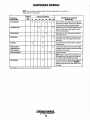
MAINTENANCE SCHEDULE
A
WARNING: Never attempt to perform any service while the engine is
running. Wear the proper safety equipment such as goggles and gloves, and
use the correct tools for each job. Disconnect the battery terminals when
servicing any of the engine's DC electrical equipment.
NOTE: Many a/the following maintenance procedures are simple but others are
more difficult and may require the expert knowledge of a service mechanic.
SCHEDULED
MAINTENANCE
CHECK
EACH
DAY
HOURS OF OPERATION
50
100
250
500
750 1000 1250
EXPLANATION OF SCHEDULED
MAINTENANCE
Fuel Supply
0
Unleaded gasoline with octane rating of 89 or
higher.
Fuel/Water Separator
0
Check for water and dirt in fuel (drain/replace filter
if necessary).
Engine Oil Level
0
Oil level should indicate between FULL and LOW on
dipstick.
Coolant Level
0
Check at recovery tank; if empty, check at manifold.
Add coolant if needed.
0
Inspect for proper tension (3/8' to 1/2" deflection)
and adjust if needed. Check belt edges for wear.
Drive Belts
Weekly
Visual Inspection of Engine
0
NOTE: Keep engine suiface clean. Dirt arul
oil will inhibit the engine:s ability to remain
coo!.
Spark Plugs
0
0
Generator
Carburetor Filler Screen
Starting Batteries
(and House Batteries)
0
0
0
0
'Adiustthe Valve
Clearances
0
Air Screen (Flame Arrester)
0
0
Engine Hoses
Governor
0
0
0
0
0
0
0
0
0
0
0
0
0
Check gap; inspect for burning and corrosion.
Check that AC connections are clean and secure
with no chafing - see GENERATOR INFORMATION
for additional information.
Initial change at 50 hrs, then change every 250 hrs.
Every 50 operating hours check electrolyte levels
and make sure connections are very tight. Clean off
excessive corrosion.
Weekly
Engine Oil
Exhaust System
0
0
0
Check for fuel, oil and water leaks. Inspect wiring
and electrical connections. Keep bolts & nuts tight.
Check for loose belt tension.
0
0
0
0
0
O·
0
Initial engine oil & filter change at 50 hrs .• then
change both every 100 hours.
Initial adjustment at 50 hrs .• then every 500 hrs.
0
Clean at 50 hours, then every 100 hours.
0
0
0
0
Initial check at 50 hrs., then every 250 hrs. Inspect
for leaks. Check siphon break operation. Check the
exhaust elbow for carbon and/or corrosion buildup
on inside passages; clean and replace as necessary.
Check that all connections are tight.
0
0
D
D
D
Hose should be hard & tight. Replace if so11 or
spongy. Check and tighten all hose clamps.
0
D
D
D
D
Change oil every 250 hours.
Lubricate linkage arm periodically.
'WESTERBEKE recommends this service be periormed by an authorized mechanic.
Engines & Generators
10
(continued)
MAINTENANCE SCHEDULE
NDTE: Use the engine hourmeter gauge 10 log your engine hours or record your
engine hours by running lime.
SCHEDULED
MAINTENANCE
Heal Exchanger
CHECK
EACH
DAY
HOURS OF OPERATION
50
100
250
500
D
D
D
D
D
Raw Water Pump
D
Clean or repiace anode. Open heal exchanger end
cap and clean out debris. Remove every 1000 hours
for professional cleaning and pressure testing.
D
Remove pump cover and inspect impellertor wear;
replace 0 needed. Also replace gasket Lubricate
both when reassembling.
Drain, flush, and refill cooling system with appropriate antoreeze mix.
D
D
EXPLANATION OF SCHEDULED
MAINTENANCE
D
D
'Starter Motor
'Engine Cylinder
Compression and
Valve Clearance
D
D
Coolant System
Distributor
750 1000 1250
D
Check solenoid and motor for corrosion. Remove
and lubricate. Clean and lubricate the Start motor
pinion dlive.
Check ignition timing. Check condition of distlibutor cap and rotor.
D
D
D
D
'Engine Timing Belt
Incorrect valve clearance will resuft in poor engine
performance; check compression pressure and timing,
and adjust valve clearances.
Remove and replace.
NOTE: Failure to replace the timing beft at the recommended interval could resuft in timing beft failure resufting in major damage to the engine.
'Exhaust Elbow
Test exhaust elbow for casting integrity. Replace if
casting is corroded or deteliorated. WARNING: A
defective exhaust elbow can cause carbon monoxide leakage!
D
'WESTERBEKE recommends thiS service be performed by an authonzed mechamc.
Engines & Generators
11
ENGINE COOLING CIRCUIT
DESCRIPTION
The engine's coolant temperature is thennostatically
controlled.
The generator's engine is fresh water cooled (engine coolant)
by an engine-mounted heat exchanger. Raw water is pumped
through the heat exchanger by a belt-driven, positive
displacement impeller pump. Mtcr the raw water cools the
fuel in the gasdenser and cools the engine coolant in the heat
exchanger, it mixes with the engine's exhaust gases, cools the
exhaust hose, and discharges overboard.
The engine's cooling system should be drained, flushed out,
and refilled with a fresh mixture of coolant at 750 operating
hours or every two years.
A
critical; almost half of engine failures can be traced
back to cooling system corrosion.
The engine's coolant is circulated by a belt-driven centrifugal-type metal impeller pump mounted on the front of the
engine.
COOLANT
CAUTION: Proper cooling system maintenance is
PRESSURE CAP
TANK
MANIFOLD
BLEED
PETCOCK
THERMOSTAT
EXHAUST
FRESH WATER
COOLANT
. .
RAW WATER
"
EXCHANGER
FRESH WATER
COOLANT PUMP
DRAIN
ZINC
ANODE
~
WESTERBEKE
Engines & Generators
12
ENGINE COOLING CIRCUIT
THERMOSTAT
DRAINING THE COOLANT
A thermostat controls the coolant temperature as the coolant
continuously flows through the closed cooling circuit. When
the engine is first started the closed thermostat prevents
coolant from flowing (some coolant is by-passed through a
hole in the thermostat to prevent the exhaust manifold from
overheating). As the engine warms up, the thermostat gradually opens. The thermostat is accessible and can be checked,
cleaned, or replaced easily. CarTy a spare thermostat and gasket.
Remove the manifold pressure cap, loosen the water drain
located on the left side of the engine block just under the
manifold and loosen the heat exchanger drain plug.
REFILLING THE COOLANT
Slowly pour clean premixed coolant into the manifold.
NOTE: Open the air bleed petcock on the exhaust manifold to
help remove air from the system. When a steady flow of
coolant appears at the drain, close the water drain plug, fill
the system and close the petcock.
Start the engine and bring it to operating temperature.
Monitor the coolant in the manifold and add as needed. Fill
the manifold to the filler neck and install the pressure cap.
Remove the cap on the coolant recovery tank and fill with
coolant halfway between LOW and MAX, and replace the
cap.
Run the engine and observe the coolant expansion flow into
the recovery tank.
TO COOLANT
RECOVERY TANK
PRESSURE CAP
FROM COOLANT
RECOVERY TANK
COOLANT EXPANSION
COOLANT RETRACTION
After checking for leaks, stop the engine and anow it to cool.
Coolant should drain back into the cooling system as the
engine cools down. Add coolant to the recovery tank if
needed. Clean up any spilled coolant.
NOTE: Periodically check the condition of the pressure cap.
Ensure that the upper and lower rubber seals are in good
condition and check that the vacuum valve opens and closes
tightly. Carry a spare cap.
THERMOSTAT TEST
A
WARNING: Always check the coolant level at the
coolant recovery tank. If the engine is /Jot, allow it to
cool before checking. HOT COOLANT and STEAM can
cause INJURY or DEATH! 00 not check the coolant at
the manifold unless the engine is cool!
If you suspect a faulty thermostat, place it in a pan of water and
bring to a boil. A working thermostat should open about 1/2".
Engines & Generators
13
ENGINE COOLING CIRCUIT
RAW WATER PUMP
HEAT EXCHANGER
The raw water pump is a self-priming, rotary pump with a
non-ferrous housing and a Neoprene impeller. The impeller
has flexible blades which wipe against a curved cam plate
within the impeller housing, producing the pumping action.
On no account should this pump be run dry. There should
always be a spare impeller and impeller ccver gasket aboard
(an impeller kit). Raw water pump impeller failures occur when
lubricant (raw water) is not present during engine operation.
Such failures are not warrantable, and operators are cautioned
to make sure raw water flow is present at start-up. The raw
water pump should be inspected periodically for broken or
tom impeller blades. See MAINTENANCE SCHEDULE.
Cool raw water flows through the inner tubes of the heat
exchanger. As the engine coolant passes around these tubes
the heat of the internal engine is conducted to the raw water
which is then pumped into the exhaust system and discharged.
The engine coolant (now cooled) flows back though the
engine and the circuit repeats itself.
The engine coolant and raw water are independent of each
other; this keeps the engine's water passages clean from the
harmful deposits found in raw water.
TO ENGINE BLOCK
~t
HEAT EXCHANGER
FROM RAW WATER PUMP
t
RAW
WATER IN
1
GASKET
ZINC
ANODE
COOLANT
DRAIN
END CAP
t
TO HEAT
EXCHANGER
FROM
GASDENSER
REPLACE
NEW
RAW WATER PUMP
REPLACE
ZINC ANODES
CLEAN AND
REPLACE
A zinc anode (or pencil) is located in the raw water cooling
circuit within the heat exchanger. The purpose of the zinc
anode is to sacrifice itself to electrolysis action taking place
in the raw water cooling circuit, thereby reducing the effects
of electrolysis on other components of the system. The condition of the zinc anode should be checked monthly and the
anode cleaned or repJaced, as required. Spare anodes should
be carried onboard. The area in the exchanger where the
anode is located should periodically be cleaned of anode
debris. Take care not to lose the small O-ring that nestles
between the heat exchanger end gasket and the ccver.
CHANGING THE RAW WATER PUMP IMPELLER
NOTE: Coat the replacement impeller blade tips with petroleum jelly before installing.
A
CAUTION: The raw water intake valve (seacock)
must be closed when servicing any components of the
raw water system, and must be re-opened before starting the engine.
DRIVE BELT ADJUSTMENT
A
CAUTION: The drive belt must be properly tensioned
for the belt-driven water pumps to function properly.
For the raw water pump/fresh water pump drive belt tension
adjustment procedure, see DRIVE BELTS ADJUSTMENT
under ENGINE ADJUSTMENTS.
-.y-
WESTERBEKE
Engines & Generators
14
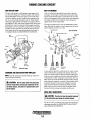
FUEL SYSTEM
These gasoline filters must have metal bowls (not "seethrough") to meet U.S. Coast Guard requirements. The metal
bowls have drain valves to use when checking for water and
impurities.
GASOLINE
Use unleaded 89 octane or higher gasoline. When fueling,
follow U.S. Coast Guard regulations, close off all hatches
and companionways to prevent fumes from entering the boat,
and ventilate after fueling.
NOTE: The generator compartment should have a gasoline
fume detector/alarm properly installed and working.
A
WARNING: Shut off the fuel valve at the tank
when servicing the fuel system. Take care in catching
any fuel that may spill. DO NOT allow any smoking,
open flames or other sources of fire near the fuel system when servicing. Ensure proper ventilation exists
when servicing the fuel system.
Ii
,I
GASOLlNEJWATER
SEPARATOR
CARBURETOR
FUEL PUMP
The carburetor is a single barrel downdraft type with a solenoid-activated electric choke and electric fuel shutoff solenoid.
Periodically check the fuel connections to and out of the pump
and make sure that no leakeage is present and that the fittings
are tight and secure. The DC ground connection at one of the
pump's mounting bolts should be dean and well secured by the
mounting bolt to ensure proper pump operation.
A
WARNING: Fuel leakage at the fuel pump or its
connections is a fire hazard and should be corrected.
Make sure proper ventilation exists whenever servicing
fuel system components.
GASDENSER
The gasdenser consists of a portion of the fuel line that is
coiled around the raw water intake line and insulated. It is
located between the raw water intake and the raw water
pump. The gasdenser cools the fuel to prevent vapor lock.
RAW WATER INTAKE
FUEL IN
CARBURETOR
GASOLINE/WATER SEPARATOR AND FILTER
....
A primary fuel filter of the water separating type must be
installed between the fuel tank and the engine to remove
water and other contaminants from the fuel before they can
be carried to the fuel system on the engine.
TO CARBURETOR
Most installers include a type of filter/water separator with
the generator installation package as they are well aware of
the problems that contaminants in the fuel can cause.
FUEL
"'""" WESTERBEKE
Engines & Generators
15
ENGINE LUBRICATING OIL
DESCRIPTION
Use a heavy duty engine oil with an API classification of SJ.
Change the engine oil after an initial 50 hours of break-in
operation and every 100 hours of operation thereafter. For
recommended oil viscosity see the following chart:
Operating Temperature
Oil Viscosity
Above 68" F (20" C)
SAE 30, 10W-30 or 15W-40
41" - 68" F (5"_20" C)
SAE 20 or 10W-30
Below 41" F (5" C)
SAE 10W-30
A
A
WARNING: Used engine oil contains harmful
contaminants. Avoid prolonged skin contact. Clean skin
and nails thoroughly using soap and water. Launder or
discard clothing or rags containing used oil. Discard
used oil properly.
REPLACING THE OIL FILTER
CAUTION: 00 not allow two or more brands of
engine oil to mix. Each brand contains its own addi·
tives; additives of different brands could react in the
mixture to produce properties harmful to your engine.
CHANGING THE ENGINE OIL
The engine oil should be warm. Remove the oil drain hose
from its attachment bracket and lower it into a container and
allow the oil to drain, or attach a pump to the end of the drain
hose and pump the old oil out. Make sure the oil drain hose
is properly secured in its holder after all of the old oil has
been drained.
Always observe the old oil as it is removed. A yellow/gray
emulsion indicates the presence of water in the oil. Although
this condition is rare, it does require prompt attention to
prevent serious damage. Call a competent mechanic if water
is present in the oil. Raw water present in the oil can
be the result of a fault in the exhaust system attached to the
engine and/or a siphoning through the raw water cooling
circuit into the exhaust, filling it up into the engine.
When removing the used oil filter, you may find it helpful to
punch a hole in the upper and lower portion of the old filter
to drain the oil into a container before removing it. This helps
to lessen spiI1age. An automotive filter wrench should be
helpful in removing the old oil filter, Place some paper towels
and a plastic bag around the filter when unscrewing it to catch
any oil that's in the filter. Inspect the old oil filter as it is
removed to make sure that the rubber sealing gasket comes
off with the old oil filter. If this rubber sealing gasket remains
sealed against the oil filter adapter, gently remove it. When
installing the new oil filter element, wipe the filter gasket's
sealing surface on the oil filter adapter free of oil and apply a
thin coat of clean engine oil to the rubber gasket on the oil
filter. Screw the filter onto the threaded oil filter nipple, and
tighten the filter firmly by hand.
NOTE: Use genuine WESTERBEKE oil fillers. Generic fillers
are not recommended.
REFILLING THE OIL SUMP
Add fresh oil through the valve cover. After refilling the oil,
run the engine for a few moments while checking the engine's
oil pressure. Make sure there is no leakage around the new
oil filter or from the oil drain system, and then stop the
engine. Then check the quantity of oil with the lube oil dipstick. Fill to, but not over, the FULL mark on the dipstick.
OIL DRAIN HOSE
OIL CONTAINER
....v- WESTERBEKE
Engines & Generators
16
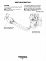
REMOTE OIL FILTER (OPTIONAL)
INSTALLATION
To install, simply remove the engine oil filter and thread on
WESTERBEKE's remote oil filter kit as shown. Always
install this kit with the oil filter facing down as illustrated.
This popular accessory is used to relocate the engine's oil filter from the engine to a more convenient location such as an
engine room bulkhead.
Contact your WESTERBEKE dealer for more information.
NOTE: Refer to REPLACING THE OIL FILTER for instruc-
NOTE: Westerbeke is not responsible for engine failure due to
tions on removing the oil filter.
incorrect installation of the Remote Oil Filter.
FASTEN SECURELY TO A BULKHEAD
(SCREWS ARE OWNER SUPPLIED).
APPLY A THIN COAT OF CLEAN OIL TO THE D-RING
WHEN INSTALLING THIS KIT. THREAD THE KIT ON,
THEN TIGHTEN (BY HAND) AN ADDITIONAL 3/4
TURN AFTER THE D-RING CONTACTS THE BASE.
~PPLYI'!~I~. ~OA~OF CLEAN Oil TO
WHEN INSTALLING.
WHEN THE F!lTER CONTACTS THE BASE,
TIGHTEN IT (BY HAND) A 3/4 TURN MORE.
"SlY'
WESTERBEKE
Engines & Generators
17
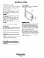
DC ELECTRICAL SYSTEM
12-VOLT DC CONTROL CIRCUIT
BATTERY CHARGING
The DC Circuit on the BCGTC functions to start, operate and
stop the generator's engine. The circuit is best understood by
reviewing the DC Wiring Diagram and Wiring Schematic.
The engine's DC wiring is designed with three simple basic
circuits: start, run and stop.
The generator supplies a continuous 17 amp charge from its
battery charger to the starting battery.
BATIERY
CHARGER
The engine has a 12 volt DC electrical control circuit that is
shown on the Wiring Diagrams. Refer to these diagrams
when troubleshooting or when servicing the DC electrical
system or the engine.
BAmRIES
A
BLACK
CAUTION: To avoid damage to the banery charg-
GREEN
ing circut, never shut off the engine banery switch
while the engine is running. Shut off the engine banery
switch, however, to avoid electrical shorts when working on the engine's electrical circuit.
YELLOW
RED
Specifications
COMPONENT TESTING
The minimum recommended capacity of the battery used in
the engine's 12-volt DC control circuit is 300 CCA.
All DC voltage measurements are made to the engine battery
negative ground point unless specified otherwise. In making
test measurements, make sure that a good ground for the
meter is established, preferably the point where the negative
battery is connected to the engine. Battery positive voltage is
indicated as B+ and should measure no Jess than 11.5 volts.
Battery Maintenance
Review the manufacturer's recommendations and then establish a systematic maintenance schedule for your engine's
starting batteries and house batteries.
AC voltage measurements should be made with a true RMS
AC meter to insure measurement accuracy.
• Monitor your voltmeter for proper charging during engine
operation.
Relay. The relays used in the control system have coils
which are polarized by the fact that they have internal free
wheeling suppression diodes across them. Relay coil terminal
86 must be maintained (+), tenninaI85(-). The relay coil is
rated 12V DC, and the coil resistance is typically 85 ohms.
With B+ on terminal 86, direct grounding of terminal 85 is
permissible for testing purposes.
• Check the electrolyte level and specific gravity with a
hydrometer.
• Use only distilled water to bring electrolytes to a proper
level.
• Make certain that battery cable connections are clean and
tight to the battery posts (and to your engine).
• Keep your batteries clean and free of corrosion.
A WARNING: Sulfuric acid in lead baneries can
cause severe burns on skin and damage clothing. Wear
protective gear.
~
WESTERBEKE
Engines & Generators
18
DC ELECTRICAL SYSTEM
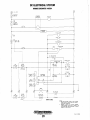
WIRING DIAGRAM #42834
OIL TEMP SWITCH INC)
[ ~
1)111111
~
+
1
n
!
-Ll
---11'
'
.-
'"
.
•
Engines & Generators
19
Rev. E 3/2S/98
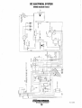
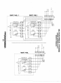
DC ELECTRICAL SYSTEM
WIRING SCHEMATIC #42834
r
c+: , 12
'-
-
VDC
~I, ~~n2~Y
STARTER
SOLENO I D
r- - - I
,,
CD
r
ICIRCUIT
I BREAKER
30
KI
,
,
,
,
,
,
,,
,
,
,L. _ _ _ ,
1 25 AMP
(
STARTER
"
I
BATTERY
CHARGER
FUEL PUMP
fI
! AMP
FUEL SOL.
r
I ®STOP SW
• ,I- 1, CKT I ( NC)
,,
,
,
,
HOUR METER
DISTRIBUTOR
COil
"",,
I
L------ 1
,
,
,
,
,,,
,
Oil
TE~P
':WITCH
7'0
CHOKE SOL.
t)/S40~
n
START
ON
L~
K I-START
IN4002
-T~·
~-,
TO
DIODE
SWljTCH
§..W.!...:3-~
DIODE
86
CKT20lQ)
®
,-EXHAUS,T
SJf~~H
OIL
PRESS.
~
\-
~
K2-RUN
OVERSPEED
~ DlODE
SHUT DOWN
n
86
"
85
I~I
I N4002
,";,
Cll'
(-
85
L,'1:J
_I
SWITCH
"
J
T1
13
~L::J
WATER ~
TEMP
SWITCH\H
JUMPER
TSI I
I
?J,
TS! 2
ON
SWITCH
I
I
J
T81
START
SWITCH
!... -~.i _~ -~oL
L __ I
L_I_I
I
I
I
_...I
"'-/
TBI ,
/
'-
'"
STOP SW
CI5JU~~)
""I
I" -
i
RU~
"'-
-
-
-
I
!.... ___ ..J~ - - _ .... _ - - -
'"
lNDICATDR
/
-D- - - - - - - - - - - - - -
/
"'-
1
I
.
"1=
-IWSTRUIIENTS- _ _ _ _ _ _ _ _ _ _ _ _ _ I
L_j_1
CKT2~ _ _ _ _ _ _ _ _ _ _ _ _ _ _ _ I
REMOTE PME!...
l!QllL
I. All WIRE iI6AWG(IOSDEG C SOOV-ALPHAI
!858/19-lm-W-i6878D TYPE 6) UNLESS
SPECIFIED OTHERWISE.
2. WARNING - RELAYS KI. K2 HAVE INTERNAL
o lODES ACROSS THE I R CO I LS, POLAR lTY AS
INDICATED !-lUST BE MAINTAIIIED TO AVOID
DAMAGE TO THE RELAYS,
Engines & Generators
20
Rev. E 3/28/98
~
~
~
".
".
-<
0
-< -<
0
=
r----
------------------------------------T--------------------------------------1
I
I
I
LED
~~
Nm~
...... Qo!1'l
i
START/STOP SW
CKT 2
"I
I
=~
CKT 1 I
ON SW
l-
=J
I
61S V
I~
sIS I41S I--
1& 3 ~
I~
2
~
I~
:~
IS l-
I
'-
[LED~
I
I
I
I
I
I
I
I
I
I
I
I
I
I
,
r
"
START/STOP SW
CKT 2
I
I
~I
1
6
I'"
"
'?
4c
ON SW
L-
I =J
1
'2
' 3
I Ii'l I Ii'l II
=
"" "
0
4
S
rn
6
TBI
\
,
I
I
I
I
I
I
I
I
SIS 1/
CKT II
, I
I
I
I
I
I
I
G>
~
--I
-j
I)
REMOTE PANEL 1
REMOTE PANEL 2
=
~
0= =
REMO\
JUMPE
1& 3 ~ 1/ :
I~
2
~
I'"'
I~
I~
I ~
CI
C')
I
I
I
I'
== m
m
==
m Z
:s:1n
....
I
I
~I'
l-
==
f)
,
I
-1-
mj!;
;g~
~-----------------------------------------~----------- --------------------------_.
fila!
~ ....
ji!i:S:
.I::'*"
~
Olll'l
~
o)ll
0
~
-< -<
ill,"
~
" . ".
r-------
LED
REMOTE PANEL
-----------------------------------,
i
START/STOP SW
CKT 2
I
I
=*
CKT 1 I
ON SW
I
=J
6
~S~
'"'
~
~4
L-
~
3 c
2
I'"
I
I
I
-
I
I
I
I
I
I
I'"
I
I
I
I
I
I
I
I
I
I
I
I
I
I
I
I
L ___________________________________________ J
'i'J
~
0= =
er ~
!a
G>
= = -< -<
0
!!!~
-<
""
=
"
~ 04 ~ ~
(i'J
\
REMOV
JUMPE
TBI
il;e:
C ')
~
~
m
==
ENGINE ADJUSTMENTS
NOTE: WESTERBEKE recommends that the following engine
adjustments be performed by a competent engine mechanic.
The information below is provided to assist the mechanic.
ENGINE SPEED (HERTZ) ADJUSTMENT
Governor Maintenance
Governor
1. Periodically lubricate the linkage arm attaching points at
the governor arm and throttle lever. Use a graphite lubricant or equivalent.
The belt-driven, mechanically operated governor maintains the
engine's rpm under various load conditions. Engine speed
determines the hertz and voltage output of the generator.
NOTE: Free movement of this linkage arm is important for
p"roper governor/throttle operation.
Governor Adjustments
2. Governor oil capacity -
Operate the generator to bring the unit up to operating temperature before adjusting the governor.
NOTE: Do not overfill the governor.
3. Change the governor oil every 250 hours of operation.
NOTE: If the governor is severely out of adjustment, manually
3 ounces 10/30 engine oil.
To change the oil, remove the governor from the engine,
remove the oil fill and the fill level plug, and drain all the
oil. Reinstall on the engine and fill with 3 ounces of 10/30
engine oil. Replace the plugs.
adjust the linkage at no-load to obtain a safe output voltage
before proceeding with the adjustment.
There are three adjusting points on the governor (see i1lustration).
4. Periodically adjust the governor belt tension (see DRIVE
BELTS ADJUSTMENT). Since belts stretch slightly, this
stretching wil1, to some degree, affect the govenor's
action.
1. Increase/Decrease Speed Adjustment. This adjusting bolt
sets the no-load speed of the engine. (The linkage ann
between the governor ann and throttle lever should be
adjusted to hold the throttle full open when the engine is
not running.) Make sure this linkage moves freely and that
the ball joint connectors are properly lubricated. Use
graphite lube for this purpose. Disconnect the ball joint and
apply graphite lube to the inside of the joint.
TORQUING THE CYLINDER HEAD BOLTS
After the initial break-in period (approximately 50 hours), the
cylinder head bolts should be re-torqued.
Tighten the cylinder head bolts according to the sequence
shown. Make sure the engine is cold when this is done, and
loosen one head bolt one-half turn and then tighten it
between 43-51 lb-ft (60-70 Nm). Then proceed to the next
head bolt in the sequence. Tighten the RS (rocker cover stud)
securely.
2. Hunting/ReguliltWnAdjustment_ If the variation in engine
speed between no-load and full-load is too great, adjust this
eye bolt to draw the spring closer to the lever hub. The
increase/decrease speed bolt may need to be adjusted as
well.
If the governor surges under load, adjust this eye bolt to
move the spring away from the lever hub (check speed
adjustment).
6
4
2
7
3
5
3. Bumper Screw Adjustment. This screw is used to remove a
no-load surge ONLY. NEVER turn the bumper screw into
the governor so far that it increases the no-load speed.
FRONT OF
ENGINE
ARM
Oil FILL
B
CARBURETOR
THROTILE
LEVER
REGULATION
ADJUSTMENT
SPEED An.""
GOVERNOR
"'T>"Nl
Engines & Generators
22
Rev.611f98
ENGINE ADJUSTMENTS
NOTE: WESTERBEKE recommends that the following engine
adjustments be performed by a competent engine mechanic.
The information below is provided to assist the mechanic.
VALVE CLEARANCE ADJUSTMENT
IGNITION TIMING
NOTE: Retorque the cylinder head bolts before adjusting the
1. Attach a timing light to the #1 spark plug and mark the
front timing pointer to indicate 18°. Locate the timing
mark on the crankshaft pulley and mark it with white
chalk or a crayon.
engine's valves (see TORQUING THE CYLINDER HEAD
BOLTS).
1. Remove the rocker cover and gasket.
2. Adjust the intake and exhaust valves in the firing order of
the engine (1-3-2), as follows:
2. Start the engine and warm it up to its normal operating
temperature. Make sure the generator is operating without
a load on it.
Rotate the crankshaft in its nonnaI direction of rotation,
placing the No. I piston at the IDC (Top Dead Center) of
its compression stroke with the intake and exhaust valves
completely closed. Then adjust the intake and exhaust
valve clearances for cylinder No. ].
3. Using the timing light, align the timing mark in the front
crankshaft pulley so it is just slightly before the first timing pointer. Do this by loosening and slowly rotating the
distributor body. Use the following timing specifications:
Valve clearances:
Intake valves - 0.20 mm (.008 in)
Exhaust valves - 0.30 mm (.012 in)
Timing Specifications: 18° ±
load on generator)
.so BIDC at 3600 rpm (no
tGNITION TIMING
Repeat the above procedure to adjust the intake and exhaust
valves for No.3 cylinder, then repeat this procedure once
more to adjust the intake and exhaust valves for No.2
cylinder.
3. Replace the rocker cover along with a new rocker cover
gasket.
Rocker cover torque: 2.9-5.1 Ib-ft (0.4-0.7 kg-m)
SPARK PLUGS
The spark plugs should be cleaned and rcgapped after the
first 50 hour break-in period, then inspected every 250 hours
thereafter and replaced as needed.
VALVE
CLEARANCE
ADJUSTMENT
CHOKE SOLENOID
A WARNING: Do not remove the spark plugs while
The choke solenoid is a 12 volt DC operated unit that functions to close the choke plate in the carburetor when the ON
switch is depressed during engine start-up.
the engine is hot. Allow the engine to cool before
removing them.
The choke solenoid de-energizes once the engine starts and
the ON switch is released. Some unstable running may be
present when the engine starts cold but should smooth out as
the engine reaches operating temperature.
Spark plug gap: 0.028 - 0.031 in. (0.7 - 0.8 mm).
Spark plug torque: 10.8 -15.2lb-ft (1.5 - 2.1 kg-m).
NOTE: Loc-tite Anti-Seize applied to the threaded portion of
the spark plugs will retard corrosion, making future removal
of the spark plugs easier.
WEAR AND
Keep this solenoid dry and periodically lubricate the linkage
between the solenoid and the choke lever.
CARBON
BURNT CONDITION
SPARK PLUG
INSPECTION
I---D""GE AND
DETERIORATION
CHOKE
SOLENOID
~
WESTERBEKE
Engines & Generators
23
Rev. 6(1198
ENGINE ADJUSTMENTS
NOTE: WESTERBEKE recommends that the following engine
adjustments be performed by a competent engine mechanic.
The information below is provided to assist the mechanic.
CARBURETOR ADJUSTMENT
DRIVE BELTS ADJUSTMENT
Basic Jet Adjustment is performed with the generator operat-
The drive belts must be properly tensioned. Excessive drive
belt tension can cause rapid wear of the belt and reduce the
service life of the fresh water pump's bearing. A slack belt or
the presence of oil on the belt can cause belt slipping, resulting in high operating temperatures.
ing. Screw the jet slowly in until it seats, then back it out
1-1/2 to 2 turns.
NOTE: An idle mixture jet adjusted too far off its seat can
induce a sooty exhaust discharge at engine start-up and shutdown.
The BCGTC generator has two drive belts, one for the governor and one for the raw water pump/fresh water pump. The
tension adjustment procedure for both belts is as follows:
NOTE: At idle speed, oil pressure will be lower than the rating
afthe oil pressure switch. Jump this switch to prevent engine
shutdown at idle speed.
1. Remove the belt guard.
Run Mixture Jet. This mixture jet is presized at the factory
and is not adjustable. The idle mixture jet adjustment can be
made in the 3600 rpm range to improve engine performance.
2. To adjust the governor drive belt, loosen the two governor
mounting bolts.
To adjust the raw water pump/fresh water pump drive
belt, loosen the two raw water pump mounting bolts.
3. With the belt(s) loose, inspect for wear, cracks and frayed
edges, and replace if necessary.
4. To loosen or tighten the governor drive belt, slide the governor in or out as required, then retighten its mounting
bolts.
FLAME
To loosen or tighten the raw water pump/fresh water
pump drive belt, slide the raw water pump in or out as
required, then retighten its mounting bolts.
ARRESTER
5. The drive belts are properly adjusted if they can be
deflected no less than 3/8 inch (10mm) and no more than
1/2 inch ( 12mm) as the belt is depressed with the thumb
at the midpoint between the two pulleys on the longest
span of the belt.
NOTE: Maintain a 22 lb pressure to the belt's outer face
for proper belt operation. Spare belts should always be
carried on board.
LINKAGE
ARM
A
WARNING: Never attempt to check or adjust a
drive belt's tension while the engine is in operation.
6. Operate the generator for about 5 minutes, then shut down
the generator and recheck the belt(s) tension.
7. Replace the belt guard.
IDLE
MIXTURE --k'<::~~
SC!iEW
FUEL SHUT-OFF
SOLENOID
CARBURETOR
Engines & Generators
24
ENGINE ADJUSTMENTS
NOTE: WESTERBEKE recommends that the following engine
adjustments be performed by a competent engine mechanic.
The information below is provided to assist the mechanic.
TIMING BELT INSPECTION AND REPLACEMENT
5. Remove the timing belt.
NOTE: If the timing belt is to be reused, draw an arrow on
the belt back to indicate the direction o/rotation (clockwise).
Timing Belt Removal
it. CAUTION: Water or oil on the timing belt severely
reduces the service life of the belt. Keep the timing
belt sprocket and tensioner free of oil and grease.
These parts should never be cleaned. Replace if serio
ously contaminated with dirt or oil. If oil is evident on
these parts, check the front case, oil pump oil seals,
and camshaft oil seals for a possible oil leak.
(
1. Turn the crankshaft c10ckwise to align the timing mark on
the camshaft sprocket and timing belt rear cover.
Camshaft Sprocket Removal
NOTE: always turn the crankshaft clockwise.
TIMING MARK
1. Remove the bolt without turning the camshaft.
2. Remove the plug on the left surface of the cylinder block
and insert a rod with a diameter of8mm (0.31in.) to lock
the counterbalance shaft.
NOTE: Be sure to use an inserting rod with a diameter of
8mm (0.31 in.).
__E;;;~~~~ROO
65 MM (2.6 IN) .
j:)
COUNTERBALANCE
SHAFT
Oil Pump Sprocket Flange Nut Removal.
CYLINDER
BLOCK
1. Remove the plug from the left side of the cylinder block.
2. Insert an 8 mm (0.31 in.) diameter round bar to lock the
counterbalance shaft.
3. Loosen the timing belt tensioner nut.
3. Remove the nut.
4. Move the timing belt tensioner toward the water pump,
and temporarily tighten the nut to hold the tensioner in
that position.
TIMING BELT TENSIONER
PUMP
""" WESTERBEKE
Engines & Generators
25
ENGINE ADJUSTMENTS
NOTE: WESTERBEKE recommends that the following engine
adjustments be performed by a competent engine mechanic.
The information below is provided to assist the mechanic.
Crankshaft Bolt Removal
Flange Installation
1. Lock the crankshaft in position.
1. Mount the flange so that its side shown by the heavy
arrow in the illustration faces toward the sprocket.
NOTE: Do not turn the crankshaft.
FLANGE
BEARING
2. Remove the crankshaft bolt.
Timing Belt Inspection
Replace the belt if any of the following conditions exist:
1. Hardening of back rubber-back side is glossy, without
resilience, and leaves no indent when pressed with fingernail.
SPROCKET
2. Cracks on rubber back.
Crankshaft Bolt Installation
3. Cracks or peeling of canvas.
1. Lock the crankshaft.
4. Cracks on tooth bottom.
NOTE: Do not turn the crankshaft.
5. Cracks on belt.
2. Tighten the crankshaft bolt to the specified torque.
6. Abnormal wear of belt sides. The sides are normal if
they are sharp as if cut by a knife.
Oil Pump Sprocket Flange Nut Installation
7. Abnormal wear on teeth.
1. Insert a round bar into the plug hole in the left side of the
cylinder block to keep the counterbalance shaft from turning.
8. Tooth missing and canvas fiber exposed.
2. Install the oil pump sprocket.
3. Tighten the nut to the specified torque.
2.
1.
CRACKS~
OR PEELING
3.
0
ACKS
4.
ROUNDED EDGE
~,.
5.
RUBBER
EXPOSED
---If.r!S
~ABNORMAL
.........
WEAR
~ (flUffY STRAND)
NUT
Camshaft Sprocket Bolt Installation
6.
1. Tighten the bolt to the specified torque.
TOOTH MISSING
AND CANVAS
~BEREXPOSED
~
7.
8.
Tensioner Inspection
1. Replace the tensioner if the pulley binds, rattles or is noisy
when turned.
~
WESTERBEKE
Engines & Generators
26
OIL PUMP
SPROCKET
ENGINE ADJUSTMENTS
NOTE: WESTERBEKE recommends that the following engine
adjustments be performed by a competent engine mechanic.
The information below is provided to assist the mechanic.
Tensioner Spring/Timing Tensioner Installation
At this time, check that the moveable range of teeth On
the oil pump sprocket is according to specifications.
1. Install the tensioncr spring and timing belt tensioner.
Standard value: 4 to 5 teeth in forward direction
1 to 2 teeth in reverse direction
2. Hook the tensioner spring onto the bend of the timing belt
tensioner bracket and the stopper pin on the cylinder
block.
OIL PUMP
SPROCKET
3. Move the timing belt tensioner as close as possible to the
water pump; temporarily tighten the tensioner nut.
TIMING BELT
REVERSE
4. If the movable range of the oil pump sprocket exceeds
the specified range, correct as follows:
a. Pull out the round bar from the plug hole in the left
side of the cylinder block.
TENSIONER
b. Turn the oil pump sprocket one turn at a time until
the round bar can again be inserted.
Timing Belt Installation
c. Check that the movable range of the oil pump
sprocket is in the specified value.
1. Align the triangular marking on the camshaft sprocket
with a marking on the timing belt rear cover.
S. Set the timing belt over the crankshaft sprocket and
then over the oil pump sprocket and camshaft sprocket,
in that order.
2. Align the notch in the crankshaft sprocket flange with
the marking on the front casco
NOTE: Ensure that the tension side of the timing belt is
not slack. Keep the round bar inserted until the timing
belt has been placed. After this step, be sure to remove
the round bar.
3. Align the triangular marking on the oil pump sprocket
with the marking on the front case, and then insert a 65
mm (2.56 in.) or longer, 8 mm (0.31 in.) diameter
round bar into the plug hole in the left side of the
cylinder blOC~k~.~;;;~~~_~
6. Apply counterclockwise force to the camshaft sprocket
to make the belt taut on the tension side, and make
sure that all timing marks are lined up.
MARKING ON
TIMING BELT ~
REAR COVER
CAMSHAFT
SPROCKET
TRIANGULAR
MARKING ON
CAMSHAFT
SPROCKET
TENSION SIDE
TIMING BELT
TENSIONER
7. Loosen the temperorarily tightened tensioner nut on
the water pump side 1 or 2 turns, and tension the belt
making use of spring force.
~b..'~'-..L--j,-TRIANGULAR MARKING
ON OIL PUMP SPROCKET
NOTCH IN
CRANKSHAFT
SPROCKET
FLANGE
MARKING
ON FRONT
CASE
Engines & Generators
27
ENGINE ADJUSTMENTS
NOTE: WESTERBEKE recommends that the following engine
adjustments be performed by a competent engine mechanic.
The information below is provided to assist the mechanic.
8. Tum the crankshaft clockwise by nine camshaft
sprocket teeth (81") to align the timing mark on the
camshaft sprocket with the tcnsioner set mark on the
timing belt rear cover.
A CAUTION: This operation is performed to give a
proper tension to the timing belt, so do NOT turn the
crankshaft counterclockwise and push the belt to
check the tension.
9. Make sure that the timing belt teeth are engaged with
the camshaft sprocket teeth along the portion of the
sprocket shown by the curved arrow in the illustration
below. Then tighten the tcosioner nut.
10. Pull the timing belt in the center of the tension side
toward the sealing gasket line for the belt cover, as
i1lustrated. Make sure that the clearance between the
back of the belt and the sealing line is the standard
value.
Standard Value: 12mm (0.47in.)
SEALING
GASKET
/L1NE
\\0:1 ~>-_ _ 12
mm (GA7IN)
11. Pull out a rod from the plug hole on the left surface of
the cylinder block and apply the specified sealant.
Then tighten the plug to the specified torque.
Specified sealant value: 3M AID Part No. 8660 or
equivalent
Tightening torque: 15-22 Nm (11-16 ft.lbs.)
Engines & Generators
28
ENGINE TROUBLESHOOTING
When troubleshooting indicates an electrical problem, see the
DC Electrical System Wiring Diagram and Schematic, as
they may reveal other possible causes of problems not listed
below.
The following troubleshooting tables are based upon certain
engine problem indicators and the most likely causes of the
problems.
PROBLEM
Engine does not
crank.
1. Voltage drop at starter solenoid
2.
3.
4.
5.
6.
7.
8.
9.
Engine cranks but
fails to start.
PROBLEM
PROBABLE CAUSE
Engine starts, runs
and then shuts
down.
terminal.
Engine 20A circuit breaker has
tripped.
Battery is low or dead.
Loose battery connections.
Faulty wire connection.
Faulty start switch.
Faulty start relay (K1).
Faulty starter solenoid.
Raw water filled cylinders.
1. Out of fuel.
2. Engine is flooded.
3.
4.
5.
6.
7.
8.
9.
10.
11.
12.
13.
Engine starts, runs
but does not come
up to speed.
a. Carburetor float needle valve open
or damaged. Clean or replace the
needle valve.
b. Float in carburetor is leaking.
Repair or replace float.
c. Float chamber gasket damaged or
securing screws are loose. Replace
gasket and/or tighten screws.
Fuel pump inoperative.
Worn or faulty spark plugs.
High tension wires grounding (wet
system).
Faulty ignition coil.
Faulty distributor.
Faulty wire connection.
Faulty overspeed circuit board.
Replace.
Faulty run relay (K2).
Timing belt.
No engine compression.
Faulty idle adjustment.
PROBABLE CAUSE
1. Faulty shutdown switch,
(oil pressure, water or exhaust
temperature).
2. High engine water or exhaust
temperature.
3. Dirty fuel/water separator filter.
4. Mechanical check valve at the fuel
supply faulty.
5. Low oil level in sump.
6. Faulty fuel pump.
7. Faulty engine temperature
sensor.
1. Fuel line restriction.
2. Mechanical check valve at the
fuel supply is faulty.
3.
4.
5.
6.
Throttle plate binding.
Faulty fuel pump.
Faulty wire connection.
Faulty engine temperature
sensor.
7. AC generator overload.
8. High exhaust pressure.
Engine hunts.
Engines & Generators
29
1.
2.
3.
4.
5.
6.
7.
Low battery voltage.
Generator is overloaded.
Cracked distributor cap.
Faulty high tension wires.
Faulty fuel pump.
High exhaust back-pressure.
Valves are out of adjustment.
ENGINE TROUBLESHOOTING
PROBLEM
Engine misfires.
PROBABLE CAUSE
1.
2.
3.
4.
5.
6.
7.
8.
Engine backfires.
PROBLEM
Poor quality fuel.
Incorrect timing.
Dirty flame arrester.
Cracked distributor cap.
Faulty ignition wires.
Spark plugs are worn.
High exhaust back-pressure.
Valve clearances are incorrect.
High oil pressure.
engine.
No DC charge to the
starting battery.
1. Faulty connections to
battery voltage regulator.
2. Faulty battery voltage regulator.
3. Faulty bridge rectifier.
4. Faulty generator charger
windings.
1. Spark plug wires are connected
wrong.
flooded under Engine cranks but
fails to start.
4. Dirty flame arrester.
5. Cracked distributor cap.
6. High exhaust back·pressure.
1. Coolant loss. Pressure test
cooling system.
2. Faulty raw water pump impeller.
3. Belts are loose or broken.
4. Raw water pump worn.·
Blue exhaust smoke
discharge from the
engine.
1.
2.
3.
4.
Black exhaust smoke
discharge from the
engine.
1. Dirty flame arrester.
2. Faulty carburetor.
Poor performance
at generator speed.
1. Main jet clogged. Remove and clean.
2. Carburetor inlet filter clogged.
1.
2.
3.
4.
Low oil level.
Wrong SAE type oil in the engine.
Wrong type oil filter.
Relief valve is stuck.
5. Faulty oil pump.
6. Faulty engine bearings.
~
Lube oil is diluted.
High lube oil level.
Crankcase breather hose is clogged.
Valves are worn or adjusted
incorrectly.
5. Piston rings are worn
or unseated.
Remove and clean.
3. Fuel pump clogged. Remove and
replace.
4. Air intake filter screen dirty. Remove
and clean.
5. Faulty thermostat.
Low oil pressure.
1. Dirty oil or wrong SAE type oil in the
2. Relief valve is stuck.
2. Incorrect timing.
3. Engine is flooded. See Engine is
Engine overheats.
PROBABLE CAUSE
WESTERBEKE
Engines & Generators
30
GENERATOR INFORMATION
USE OF ELECTRIC MOTORS
REQUIREO OPERATING SPEED
The power required to start an electric motor is considerably
more than is required to keep it running after it is started.
Some motors require much more current to start than others.
Split-phase (AC) motors require more current to start, under
similar circumstances, than other types. They are commonly
used on easy-starting loads, such as washing machines, or
where loads are applied after the motor is started, such as
small power tools. Because they require 5 to 7 times as much
current to start as to run, their use should be avoided, whenever possible, if the electric motor is to be driven by a small
generator. Capacitor and repulsion-induction motors require
from 2 to 4 times as much current to start as to run. The CUTrent required to start any motor varies with the load connected to it. An electric motor connected to an air
compressor, for example, will require more current than a
motor to which no load is connected.
Although individual units may vary slightly, the normal
voltage and frequency of typical 60 (50) hertz engine-driven
generators described in this manual are approximately as follows: run first with no load applied, then at half the generator's
capacity, and finally loaded to its full capacity as indicated on
the generator's data plate.
The output voltage should be checked periodically to ensure
proper operation of the generating plant and the appliances it
supplies.
GENERATOR FREQUENCY ADJUSTMENT
• Frequency is a direct result of engine/generator speed, as
indicated by the following:
• When the generator is run at 3600 rpm, the AC voltage
output frequency is 60 hertz.
In general, the current required to start 115 volt motors
connected to medium starting loads will be approximately
as follows:
• When the generator is run at 3000 rpm, the AC voltage
output frequency is 50 hertz.
MOTOR SIZE
(HP)
AMPS FOR
RUNNING
(AMPERES)
AMPS FOR
STARTING
(AMPERES)
1/6
3.2
6.4 TO 22.4
1/4
4.6
9.2 TO 32.2
GENERATOR MAINTENANCE
1/3
5.2
10.4 TO 72.8
1/2
7.2
14.4 TO 29.2
Maintaining cleanliness is important. Do not allow salt, dust,
or carbon from engine exhaust to build up on either the generator or its engine.
3/4
10.2
20.4 TO 40.8
1
13
26 TO 52
Therefore, to change the generator's frequency, the generator's
drive engine's speed must be changed. A reconfiguring of the
AC output connections at the generator must also be made.
NOTE: In the above table the maximum "AMPS FOR
STARTING" is more for some small motors than for larger
ones. The reason for this is that split-phase (the hardest starting types) are used in the smaller motors only.
Because the heavy surge of current needed for starting
motors is required for only an instant, the generator will not
be damaged if it can bring the motor up to speed in a few
seconds. If difficulty is experienced in starting motors, tum
off all other electrical loads and, if possible, reduce the load
on the electric motor.
BAND
-FLANGE
FRONT COVER
REAR
CAPACITOR
P
CONTROL BOX
GENERATOR COMPONENTS
Engines & Generators
31
GENERATOR WIRING DIAGRAMS
RED
+
;-----------,'
,,
'
,,
,
2
,
3
Allicr:::
,
Cnm_mi 0Jll
.ll.
L,:-t
WINDING RESISTANCE AT 20° C TEMPERATURE
A-A
B
C-C
0
ROTATING
PART
BATTERY
CHARGER
WINDING
STATOR
WINDING
EXC
WINDING
50~!
~-2
3.058
Hz
.n.. o.i41
- - - --.n..
('.433
.n..
'-3
c·-S'-5A .n.
MODEL 4.5 KW
4-,
0·491 .!1.
'·6
0·55;t ....n..
R[
,-----------1
,
~
'8
,,,
.n..
4-.334
,o-g
.n
3. 4S"~
'io-1-
4.5.34
.n.
'o-if
3. ;r.q..
..n.
+
SOHI
2
3
Allicr::;
,
,
:__ mmniOjjj
.It
L,:-t
Hz
MODELS 7.2 KW AND 9.6 KW
Engines & Generators
32
Rev. 6/1/98
AC ELECTRICAL CONNECTIONS
+
r--------.,
iAR]i
B UA.._...J
+
WHITE
B'~-...J
rv
CIRCUIT BREAKER
I
I
I
I
I
AR]i
I
.....
I
I
_--------
4------,
120 VAC
60 HZ
(CONNECT
JUMPER)
...,..----{) 4
C
L
VA----05
1-------,
5------~
r:___:h 240/120 VAC
60 HZ
DITWlo
189HZ
666
50
HZ
(REMOVE
JUMPER)
LJ
CONNECT fOR REQUIRED FREQUENCY
AND OUTPUT VOLTAGE
A - ROTOR
BI- BATTERY CHARGE WINDING
MODEL 4.5 KW
B2- BATTERY CHARGE WINDING
MODELS 7.2 KW AND 9.6 KW
C - STATOR WINDING
D - CAPACITOR WINDING
6-------,
220 VAC
3 :
_
4
50 HZ
(REMOVE
JUMPER)
r±----Jh
"'" -
-0
N
L
A WARNING: When changing from 60Hz to 50Hz,
make certain the ground wire (white & green stripe) is
properly repositioned according to this diagram.
Engines & Generators
33
Rev. 6/1/98
LAY-UP & RECOMMISSIONING
GENERAL
FUEL SYSTEM
Many owners rely on their boatyards to prepare their craft,
including engines and generators, for Jay-up during the offseason or for long periods of inactivity. Others prefer to
accomplish lay-up preparation themselves.
Top off your fuel tanks with unleaded gasoline of 89 octane
or higher. A fuel conditioner such as STABIL gasoline stabilizer should be added. Change the element in your
gasoline/water separator and clean the metal bowl.
Re-install and make certain there are no leaks. Clean
up any spilled fuel.
The procedures which follow will allow you to perform your
own lay-up and recommissioning, or wi1l serve as a checklist
if others do the procedures.
Start the engine and allow it to run for 5-10 minutes. Check
for any leaks that may have been created in the fuel system
during this servicing and correct them. Clean up any fuel
spills.
These procedures should provide protection for your
engine/generator during a Jay-up and also help familiarize
you with its maintenance needs.
RAW WATER CIRCUIT
If you have any questions regarding lay-up procedures, caB
your local servicing dealer. He will be more than willing to
provide assistance.
Close the through-huH fitting. Remove the raw water intake
hose from the fitting. Place the end of this hose into a 5-gallon
bucket of clean fresh water. Before starting the engine, check
the zinc anode in the heat exchanger on the engine and clean
or replace it as required. Clean the raw water strainer, if one
is installed on the inside of the hull.
FRESH WATER CODLING SYSTEM
A 50-50 solution of antifreeze and distilled water is recommended for use in the fresh water cooling system at all times.
This solution may require a higher concentration of antifreeze,
depending on the area's winter climate. Check the solution to
make sure the antifreeze protection is adequate.
Start the engine and anow the raw water pump to draw the
fresh water through the system. When the bucket is empty,
stop the engine and refill the bucket with an antifreeze solution slightly stronger than needed for winter freeze protection
10 your area.
Should more antifreeze be needed, drain an appropriate amount
from the engine block and add a more concentrated mixture.
Operate the engine to ensure a complete circulation and mixture of the antifreeze concentration throughout the cooling
system. Then recheck the antifreeze solution's strength.
Start the engine and allow all of this mixture to be drawn
through the raw water system. Once the bucket is empty, stop
the engine. This antifreeze mixture should protect the raw
water circuit from freezing during the winter lay-up, as well
as providing corrosion protection.
LUBRICATION SYSTEM
With the engine warm, drain all the engine oil from the oil
sump. Remove and replace the oil filter. (Place some paper
towels and a plastic bag around the filter to catch the oil during its removal.)
Remove the impeller from your raw water pump (some
antifreeze mixture will accompany it, so catch it in a bucket).
Examine the impeller. Get a replacement, if needed, and a
cover gasket. Do not replace the impeller (into the pump)
until recommissioning, but replace the cover and gasket.
When installing the new oil filter, be sure to apply a small
amount of oil on the rubber sealing gasket at the base of the
filter. Fill the sump with the correct amount of oil for your
engine model. (Refer to the SPECIFICATIONS section of
this manual.) Use an oil with an API specification of SJ.
Run the engine and check for proper oil pressure and make
sure there are no leaks or fuel spills.
A
CAUTION: Do not leave the engine's old engine
oil in the sump over the lay-up period_ Engine oil and
combustion deposits combine to produce harmful
chemicals which can reduce the life of your engine's
internal parts.
Engines & Generators
34
LAY-UP & RECOMMISSIONING
INTAKE MANIFOLD
RECOMMISSIONING
Clean the filter screen in the flame arrester, and place a clean
doth lightly soaked in lube oil around the flame arrester to
block any opening. Also place an oil-soaked cloth in the
through-hull exhaust port. Make a note to remove cloths prior to
start-up!
The recommissioning of your WESTERBEKE engine after a
seasonal lay-up generally follows the same procedures as
those presented in the PREPARATIONS FOR INITIAL STARTUP section regarding preparation for starting and normal
starts. However, some of the lay-up procedures will need to
be counteracted before starting the engine.
STARTER MOTOR
1. Remove the oil-soaked cloths from the intake manifold
and from the through-hull exhaust port.
Lubrication and cleaning of the starter drive pinion is advisable,
if access to the starter permits its removal. Make sure the battery connections are shut off before attempting to remove the
starter. Take care in properly replacing any electrical connections removed from the starter.
2. Remove the raw water pump cover and gasket. Discard the
gasket. Install the raw water pump impeller removed during lay-up (or a replacement, if required). Install the raw
water pump cover with a new cover gasket.
3. Remove the spark plugs, wipe clean, re-gap, and install to
CYLINDER LUBRICATION
proper tightness.
Spray fogging oil into the open air intake, with the flame
arrestor removed, while the generator is running. The fogging
oil will stall out the engine and coat the valves, cylinders and
spark plugs for winter protection.
4. Reinstall the batteries that were removed during the layup, and reconnect the battery cables, making sure the terminals are clean and that the connections are tight. Check
to make sure the batteries are fully charged.
NOTE: The spark plugs will need to be removed for cleaning
and regapping at spring commissioning.
5. Note that it is not necessary to flush the antifreeze/fresh
water solution from the raw water coolant system. When
the engine is put into operation, the system will self-flush
in a short period of time with no adverse affects.
SPARE PARTS
Lay-up time provides a good opportunity to inspect your
WESTERBEKE engine to see if external items such as drive
belts or coolant hoses need replacement. Check your basic
spares kit and order items not on hand, or replace those items
used during the lay-up, such as filters and zinc anodes.
6. Start the engine in accordance with procedures in the
PREPARATIONS FOR INITIAL SDlRT-UP section of this
manual.
BATTERIES
If batteries are to be left on ·board during the lay-up period,
make sure that they are fully charged, and will remain that
way, to prevent them from freezing. If there is any doubt that
the batteries will not remain fully charged, or that they will
be subjected to severe environmental conditions, remove the
batteries and store them in a wanner, more compatible environment.
A WARNING:
Lead acid batteries emit hydrogen, a
highly·explosive gas, which can be ignited by electri·
cal arcing or a lighted cigarette, cigar, or pipe. Do not
smoke or allow an open flame near the battery being
serviced. Shut off all electrical equipment in the
vicinity to prevent electrical arcing during servicing.
Engines & Generators
35
BCGTC GENERATOR SPECIFICATIONS
ENGINE SPECIFICATIONS
Engine Type
3 cylinder, 4 cycle, overhead camshaft
wlcounterbalance shaft, carbureted,
water cooled gasoline engine
Bore and Stroke
2.56 x 2.61 in. (65.0 mm x 66.3 mm)
Total Displacement
40.3 cu. in. (.66 liter)
Bearings
Four main bearings
Combustion Chamber
Semi-spherical
Compression ratio
9.8 - 1
Firing Order
1- 3- 2
Direction of Rotation
Counterclockwise viewed from the back
end
Inclination
25 continuous, all directions
30 temporary, all directions
General
Fresh water-cooled block through raw
water-cooled heat exchanger circuit
Fresh Water Pump
Centrifugal type, metal impeller,
belt-driven
Raw Water Pump
Positive displacement, rubber impeller,
belt-driven
Raw Water Flow,
at 3600 RPM
7.0-7.5 gpm (26.4-28.3 Ipm)
measured before discharge into
water injected exhaust elbow.
Cooling Water Capacity 3.5 qts. (3.4 liters)
0
LUBRICATING SYSTEM
0
Governor
Mechanical
Type
Forced lubrication by gear pump
Oil Filter
Fuel flow, paper element spin-on
disposals
Oil Capacity
2.7 qts. (2.6 liters)
Oil Grade
API specification SJ class
FUEL SYSTEM
Fuel Pump
Electric fuel pump
Fuel
Unleaded 89 octane or higher gasoline
Distributor
Breakerless distributor
Spark Plugs
14 mm
Ignition Coil
12 volt
Flame Arrester
Metal screen type
Carburetor
Single-barrel downdraft type
AC GENERATOR SPECIFICATIONS
2 pole capacitor regulated
50/60 hertz-1.0 power factor
Type
Rating (minimum)
ELECTRICAL SYSTEM
-
Start Motor
12 volt reduction gear wlsolenoid
Starting Battery
12 volt negative ground
Battery Capacity
300 cold cranking amps (CCA) (min)
Battery Charging
Integral electriC, 17 amps
r~m
3000
3000
3000
3600
3600
3600
Model
3.75 Kw
6.0 Kw
8.0 Kw
4.5 Kw
7.2 Kw
9.6 Kw
Hz
50
50
50
60
60
60
KVA
3.75
6.0
8.0
4.5
7.2
9.6
VAC
230
230
230
120
120
120
Consult factory for 120/240 volt application
TUNE-UP SPECIFICATIONS
AIR REQUIREMENTS
Spark Plug Gap
0.031 ± .002 inches (0.8 ± 0.05 mm)
Spark Plug Torque
10.8 - 15.2 Ib-ft
Generator Cooling
225--250 CFM
(6.3-7.0 cmm)
Valve Clearances
Intake valves: 0.20 mm (.008 in)
Exhaust valves: 0.30 mm (.012 in)
Engine Combustion
(all models)
42 CFM (1.2 cmm)
Timing Specifications
18 ± .5 BTDC at 3600 rpm
(no load on generator)
Engine Cooling
100 CFM (2.8 cmm)
Cylinder Head
60 - 70 Nm 43-51 ft-Ibs
Boll Torque
see TORQUING THE CYLINDER HEAD
BOLTS under ENGINE ADJUSTMENTS
0
0
-..v- WESTERBEKE
Engines & Generators
36
Rev. 6/1/98
BCGTC GENERATOR PARTS IDENTIFICATION
CARBURETOR
GOVERNOR
FRESH WATER
FILL CAP
WATER
TEMPERATURE
SWITCH
OIL FILTER
-------1
Oil PRESSURE
SWITCH
: : i - - - - - RAW WATER
PUMP
DC BATIERY
GROUND CONNECTION
DATA TAG
ZINC ANODE
STARTER
WITH SOLENOID
RIGHT SIDE
Oil
DRAIN HOSE
Oil
FILL CAP
DISTRIBUTOR
WATER INJECTED
EXHAUST ELBOW
COIL
FRESH WATER
DRAIN PLUG
LEFT SIDE
~
WESTERBEKE
Engines & Generators
37
STANDARD HARDWARE TORQUES
NOTE: Unless stated otherwise for a specific assembly, use the following torque values when tightening standard hardware.
Grade 4
Pitch
Ib-n
Grade 7T, 8T and 8·.8
kg-m
Pitch
Ib-n
kg-m
1
5.S-S.7
0.S-I.2
6mm bolt head/nut
1
2.9-5.1
0.4-0.7
6mm bolt head/nut
Smm bolt head/nut
1.25
7.2-11.6
1.0-1.6
Smm bolt head/nut
1.25
14.5-21.7
2.0-3.0
10mm bolt headinut
1.25
13.7-22.4
1.9-3.1
10mm bolt head/nut
1.25
2S.9-39.S
4.0-5.5
10mm bolt headinut
1.5
13.0-21.7
I.S-3.0
10mm bolt head/nut
1.5
26.S-37.6
3.7-5.2
1.25 (ISO)
54.2-75.9
7.5-10.5
12mm bolt head/nut
1.25 (ISO)
25.3-39.S
3.5-5.5
12mm bolt head/nut
12mm bolt headinut
1.5
25.3-39.8
3.5-5.5
12mm bolt head/nut
1.5
50.6-65.1
7.0-9.0
12mm bolt headinut
1.75
21.7-36.2
3.0-5.0
12mm bolt head/nut
1.75
43.4-61.5
6.0-S.5
13mm bolt headinut
1.5
32.5-50.6
4.5-7.0
13mm bolt head/nut
1.5
57.9-S6.S
S.0-12.0
1.5
72.3-10S.5
10.0-15.0
14mm bolt headinut
1.5
36.2-57.9
5.0-S.0
14mm bolt headinut
14mm bolt head/nut
2
34.0-55.7
4.7-7.7
14mm bolt head/nut
2
6S.7-101.3
9.5-14.0
16mm bolt head/nut
1.5
54.2-79.6
7.5-11.0
16mm bolt headinut
1.5
10S.5-166.4
15.0-23.0
7.HO.6
16mm bolt head/nut
2
101.3-159.1
14.0-22.0
1/4 UNC
9-11
1.2-1.5
16mm bolt head/nut
2
51.4-76.7
Grade 5 Cap Screw
Grade 6T
Bmm bolt head/nut
1
4.3-6.5
0.6-0.9
Bmm bolt head/nut
1.25
10.S-15.9
1.5-2.2
1/4 UNF
lH3
1.5-1.S
IS-20
2.5-2.S
10mm bolt head/nut
1.25
21.7-32.5
3.0-4.5
5/16 UNC
10mm bolt head/nut
1.5
19.5-30.4
2.7-4.2
5/16 UNF
21-23
2.9-3.2
12mm bolt head/nut
1.25 (ISO)
36.2-57.9
5.0-S.0
3/S UNC
2S-33
3.7-4.6
5.0-7.0
3/S UNF
30-35
4.1-4.S
4.S-6.S
7/16 UNC
44-49
6.1-6.S
7/16 UNF
50-55
6.9-7.6
1/2 UNC
6S-73
9.4-10.1
1/2 UNF
73-S0
10.Hl.l
12mm bolt head/nut
12mm bolt head/nut
1.5
1.75
36.2-50.6
34.7-49.2
Engines & Generators
38
BCGTC GENERATOR HARDWARE TORQUES
Front Case, Counterbalance Shaft
Nm
ft.lbs.
Front case bolt
8-10
6-7
OJ! pump cover bolt
8-10
6-7
58-72
Oil pan bolt
10-t2
7-9
50-57
36-41
Oil drain plug
35-45
25-33
Timing tensioner nut
22-30
7-9
Oil screen bolt
15-22
11-16
Timing belt rear cover bolt
10-12
Oil pump driven gear bolt
34-40
25-29
Rear cover bolt
10-12
7-9
15+90 tum
11 + 90° tum
TIming Belt
Nm
ft. Ibs.
135-145
98-105
Timing belt cover bolt
10-12
7-9
Camshaft sprocket bolt
80-100
Oil pump sprocket nut
Crankshaft bolt
Water Pump
Water pump
8-10
Piston and Connecting Rod
6-7
Connecting rod cap nut
Rocker Arms and Rocker Shaft
0
Crankshaft, Bearing
Rocker cover shaft
29-35
21-25
Camshaft thrust plate bolt
10-12
7-9
Oil seal case bolt
10-12
7-9
Rocker arm adjust nut
8-10
6-7
Bearing cap bolt
50-55
36-40
Taper plug 1/16
8-12
6-9
Taper plug 1/8
t5-22
11-16
Water drain plug
35-45
25-33
Taper plug pt-l/4
35-45
25-33
Cylinder Block
Cylinder Head, Valve
Cylinder head bolt (cold engine)
60-70
43-5t
~
WESTERBEKE
Engines & Generators
39
METRIC CONVERSIONS
INCHES TO MILLIMETERS
Inches
mm
1
2
3
4
5
10
25.40
50.80
76.20
101.60
127.00
254.00
15
20
25
30
35
40
MILLIMETERS TO INCHES
mm
Inches
381.00
508.00
635.00
762.00
889.00
1016.00
mm
Inches
mm
Inches
1
2
3
4
5
10
0.0394
0.0787
0.1181
0.1575
0.1969
03937
15
20
25
30
35
40
0.5906
0.7874
0.9843
1.1811
1.3780
1.5748
10 MIlliMETERS = lCENTIMETER, 100 CENTIMETERS = 1 METER = 39.37 INCHES (3.3 FEET)
INCHES TO METERS
Inches
Meters
1
2
3
4
5
6
0.0254
0.0508
0.0762
0.1016
0.1270
0.1524
Inches
METERS TO INCHES
Meters
0.1778
0.2032
0.2286
0.2540
0.2794
0.3048
7
8
9
10
11
12
Inches
Meters
0.1
0.2
0.3
0.4
0.5
0.6
3.937
7.874
11.811
15.748
19.685
23.622
Meters
Inches
0.7
0.8
0.9
1.0
1.1
1.2
27.559
31.496
35.433
39.370
43.307
47.244
TO CONVERT METERS TO CENTIMETERS, MOVE DECIMAL POINT TWO PLACES TO THE RIGHT
YARDS TO METERS
Yards
Meters
1
2
3
4
5
0.91440
1.82880
2.74320
3.65760
4.57200
Yards
6
7
8
9
10
METERS TO YARDS
Meters
Meters
Yards
Meters
5.48840
6.40080
7.31520
8.22960
9.14400
1
2
3
4
5
1.09361
2.18723
3.28084
4.37445
5.46807
6
7
8
9
10
Yards
6.56168
7.65529
8.74891
9.84252
10.93614
MOVE DECIMAL POINT FOR HIGHER VALUES - e.g. 6,000 METERS = 6,561.68 YARDS
Ib
POUNDS TO KILOGRAMS
kg
Ib
kg
1
2
3
4
5
0.454
0.907
1.361
1.814
2.268
Gallons
Liters
kg
2.722
3.175
3.629
4.082
4.536
6
7
8
9
10
KILOGRAMS TO POUNDS
Ib
kg
GALLONS TO LITERS
1
2
3
4
5
3.79
7.57
11.36
15.14
18.93
1
2
3
4
5
Liters
0.47
0.95
1.42
1.89
2.37
6
7
8
9
10
Liters
Liters
Gallons
10
20
30
40
50
37.86
75.71
113.57
151.42
189.28
1
2
5
10
20
0.26
0.53
1.32
2.64
5.28
Liters
60
90
120
150
180
40
I
I
5
50
I
I
10
Liters
Liters
Pints
Liters
6
7
8
9
10
2.84
3.31
3.79
4.26
4.73
1
2
3
2.11
4.23
6.34
8.45
10.57
6
7
8
60
I
I
15
70
I
I
20
Gallons
15.66
23.77
31.32
39.62
47.54
LITERS TO PINTS
Pints
4
5
9
10
TEMPERATURE
32
I
I
0
13.228
15.432
17.637
19.842
22.046
LITERS TO GALLONS
Gallons
PINTS TO LITERS
Pints
2.205
4.409
6.614
8.818
11.023
1
2
3
4
5
Ib
75
I
I
25
85
I
I
30
95
I
I
35
105
I
I
40
Engines & Generators
40
140
I
I
60
175 212
I
I
I
I
80 100
Pints
12.68
14.79
16.91
19.02
21.13
OF
°C
SUGGESTED SPARE PARTS
WESTERBEKE MARINE GASOLINE GENERATORS
Zinc Anodes
.G~Carry several.
Spall< Plugs
Heat Exchanger End Gasket
Always carry a full set.
,
Raw Water Impeller and Gasket
Check annually.
Oil Filter
Have several aboard.
Change every 100 hours.
Oistributor Cap and Wires
Fuel Lift Pump
Solid Slate Model. Have a
spare on board.
Carry matched pairs.
Inspect every 100 hours.
and Gasket
Always carry a spare aboard.
SPARE PARTS KITS
WESTERBEKE also offers two Spare Parts Kits,
each packaged in a rugged hinged toolbox.
Kit A includes the basic spares.
Kit B is for more extensive off-shore cruising.
KIT B
Impeller Kit
Water Pump Repair Kit
Kit
KIT A
Thermostat
Impeller Kit
Zinc Anodes
Heat Exchanger Gasket
Complete Gasket Kit
Oil Filter
ZineAnodes
Heat Exchanger Gasket
Oil Filter
Drive Belts
Spark Plugs
Spark Plugs
Drive Belts
Engines & Generators
41