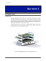
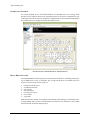
1
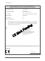
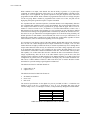
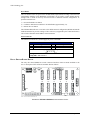
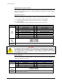
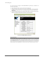
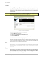
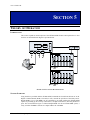
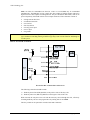
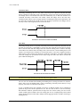
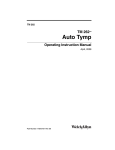
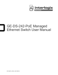
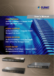
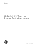
EX7000-OEM
SCALABLE OPEN-ARCHITECTURE
MICROWAVE INTERFACE
USER’S MANUAL
P/N: 82-0118-000
Release December 19, 2007
VXI Technology, Inc.
2031 Main Street
Irvine, CA 92614-6509
(949) 955-1894
VXI Technology, Inc.
2
EX7000-OEM Preface
www.vxitech.com
TABLE OF CONTENTS
INTRODUCTION
Certification ..........................................................................................................................................................5
Warranty ...............................................................................................................................................................5
Limitation of Warranty .........................................................................................................................................5
Restricted Rights Legend......................................................................................................................................5
DECLARATION OF CONFORMITY ...............................................................................................................................6
GENERAL SAFETY INSTRUCTIONS .............................................................................................................................7
Terms and Symbols ..............................................................................................................................................7
SUPPORT RESOURCES ...............................................................................................................................................8
SECTION 1....................................................................................................................................................................9
INTRODUCTION .........................................................................................................................................................9
Introduction ..........................................................................................................................................................9
Interactive Control..............................................................................................................................................10
Relay Drive Control............................................................................................................................................10
Interfacing with Other Components ...................................................................................................................11
Features...............................................................................................................................................................11
Relay Odometer.............................................................................................................................................11
Exclude Lists .................................................................................................................................................11
Scan Lists ......................................................................................................................................................11
Configuration Table ......................................................................................................................................12
Programmable MBB and BBM .....................................................................................................................12
EX7000-OEM Specifications .............................................................................................................................13
SECTION 2..................................................................................................................................................................15
PREPARATION FOR USE...........................................................................................................................................15
Overview ............................................................................................................................................................15
Unpacking...........................................................................................................................................................15
Installation Location ...........................................................................................................................................15
Driver Installation...............................................................................................................................................15
EX7000-OEM Hardware Setup ..........................................................................................................................16
Open-Collector vs. TTL Drive Lines..................................................................................................................17
Network Configuration.......................................................................................................................................17
SECTION 3..................................................................................................................................................................19
HARDWARE DESCRIPTION ......................................................................................................................................19
Overview ............................................................................................................................................................19
Digital Controller Board Detail ..........................................................................................................................19
Trigger Bus Connectors.................................................................................................................................20
Digital I/O Connector....................................................................................................................................20
Reset Button ..................................................................................................................................................22
Power Connector ...........................................................................................................................................22
Relay Driver Board Detail ..................................................................................................................................22
Digital Interface Controller Connectors ........................................................................................................23
Relay Drive Connectors ................................................................................................................................23
Power Connectors .........................................................................................................................................23
LED Connectors............................................................................................................................................24
Parallel TTL IO Ports ....................................................................................................................................24
Fan Power Connectors ..................................................................................................................................25
Address Switch..............................................................................................................................................25
Relay Banks ..................................................................................................................................................25
EX7000-OEM Preface
3
VXI Technology, Inc.
SECTION 4..................................................................................................................................................................27
WEB PAGE OPERATION...........................................................................................................................................27
Introduction ........................................................................................................................................................27
General Web Page Operation .............................................................................................................................27
Password Protection ......................................................................................................................................28
VXI Technology Logo ..................................................................................................................................29
EX7000 Title Block ......................................................................................................................................29
Soft Front Panel ..................................................................................................................................................30
Network Configuration.......................................................................................................................................30
Time Configuration ............................................................................................................................................32
Device Identify ...................................................................................................................................................34
Upgrade ..............................................................................................................................................................35
Reset ...................................................................................................................................................................35
Reboot.................................................................................................................................................................35
SECTION 5..................................................................................................................................................................37
THEORY OF OPERATION ..........................................................................................................................................37
Introduction ........................................................................................................................................................37
System Overview................................................................................................................................................37
Relay Access & Control .....................................................................................................................................38
Continuous Mode ..........................................................................................................................................39
Pulse Mode....................................................................................................................................................39
INDEX .........................................................................................................................................................................41
4
EX7000-OEM Preface
www.vxitech.com
CERTIFICATION
VTI Microwave, a business unit of VXI Technology, Inc. (VTI) certifies that this product met its published
specifications at the time of shipment from the factory. VTI Microwave further certifies that its calibration
measurements are traceable to the United States National Institute of Standards and Technology (formerly National
Bureau of Standards), to the extent allowed by that organization’s calibration facility, and to the calibration facilities
of other International Standards Organization members.
WARRANTY
The product referred to herein is warranted against defects in material and workmanship for a period of one year
from the receipt date of the product at customer’s facility. The sole and exclusive remedy for breach of any warranty
concerning these goods shall be repair or replacement of defective parts, or a refund of the purchase price, to be
determined at the option of VTI Microwave.
For warranty service or repair, this product must be returned to a VXI Technology authorized service center. The
product shall be shipped prepaid to VTI and VTI shall prepay all returns of the product to the buyer. However, the
buyer shall pay all shipping charges, duties, and taxes for products returned to VTI from another country.
VTI Microwave warrants that its software and firmware designated by VTI Microwave for use with a product will
execute its programming when properly installed on that product. VTI Microwave does not however warrant that the
operation of the product, or software, or firmware will be uninterrupted or error free.
LIMITATION OF WARRANTY
The warranty shall not apply to defects resulting from improper or inadequate maintenance by the buyer, buyersupplied products or interfacing, unauthorized modification or misuse, operation outside the environmental
specifications for the product, or improper site preparation or maintenance.
VTI Microwave and VXI Technology, Inc. shall not be liable for injury to property other than the goods themselves.
Other than the limited warranty stated above, VXI Technology, Inc. makes no other warranties, express or implied,
with respect to the quality of product beyond the description of the goods on the face of the contract.
VTI Microwave specifically disclaims the implied warranties of merchantability and fitness for a particular purpose.
RESTRICTED RIGHTS LEGEND
Use, duplication, or disclosure by the Government is subject to restrictions as set forth in subdivision (b)(3)(ii) of the
Rights in Technical Data and Computer Software clause in DFARS 252.227-7013.
VTI Microwave
A VXI Technology, Inc. Business Unit
2031 Main Street
Irvine, CA 92614-6509 U.S.A.
EX7000-OEM Preface
5
VXI Technology, Inc.
DECLARATION OF CONFORMITY
Declaration of Conformity According to ISO/IEC Guide 22 and EN 45014
MANUFACTURER’S NAME
VXI Technology, Inc.
MANUFACTURER’S ADDRESS
2031 Main Street
Irvine, California 92614-6509
PRODUCT NAME
Scalable Open-Architecture Microwave Interface
MODEL NUMBER(S)
EX7000-OEM
PRODUCT OPTIONS
All
PRODUCT CONFIGURATIONS
All
VXI Technology, Inc. declares that the aforementioned product conforms to the requirements of
the Low Voltage Directive 73/23/EEC and the EMC Directive 89/366/EEC (inclusive 93/68/EEC)
and carries the “CE” mark accordingly. The product has been designed and manufactured
according to the following specifications:
SAFETY
EN61010 (2001)
EMC
EN61326 (1997 w/A1:98) Class A
CISPR 22 (1997) Class A
VCCI (April 2000) Class A
ICES-003 Class A (ANSI C63.4 1992)
AS/NZS 3548 (w/A1 & A2:97) Class A
FCC Part 15 Subpart B Class A
EN 61010-1:2001
I hereby declare that the aforementioned product has been designed to be in compliance with the relevant sections
of the specifications listed above as well as complying with all essential requirements of the Low Voltage Directive.
December 2007
Steve Mauga, QA Manager
6
EX7000-OEM Preface
www.vxitech.com
GENERAL SAFETY INSTRUCTIONS
Review the following safety precautions to avoid bodily injury and/or damage to the product.
These precautions must be observed during all phases of operation or service of this product.
Failure to comply with these precautions, or with specific warnings elsewhere in this manual,
violates safety standards of design, manufacture, and intended use of the product.
Service should only be performed by qualified personnel.
TERMS AND SYMBOLS
These terms may appear in this manual:
WARNING
Indicates that a procedure or condition may cause bodily injury or death.
CAUTION
Indicates that a procedure or condition could possibly cause damage to
equipment or loss of data.
These symbols may appear on the product:
ATTENTION - Important safety instructions
Frame or chassis ground
Indicates that the product was manufactured after August 13, 2005. This mark is
placed in accordance with EN 50419, Marking of electrical and electronic
equipment in accordance with Article 11(2) of Directive 2002/96/EC (WEEE).
End-of-life product can be returned to VTI by obtaining an RMA number. Fees
for take-back and recycling will apply if not prohibited by national law.
WARNINGS
Follow these precautions to avoid injury or damage to the product:
Use Proper Power Source
Operating Conditions
Improper Use
EX7000-OEM Preface
To avoid electrical overload, electric shock, or fire hazard, do not
use a power source that applies other than the specified voltage.
To avoid injury, electric shock or fire hazard:
Do not operate in wet or damp conditions.
Do not operate in an explosive atmosphere.
Operate or store only in specified temperature range.
Provide proper clearance for product ventilation to prevent
overheating.
DO NOT operate if any damage to this product is suspected.
Product should be inspected or serviced only by qualified
personnel.
The operator of this instrument is advised that if the equipment is
used in a manner not specified in this manual, the protection
provided by the equipment may be impaired.
Conformity is checked by inspection.
7
VXI Technology, Inc.
SUPPORT RESOURCES
Support resources for this product are available on the Internet and at VXI Technology customer
support centers.
VTI Microwave
A VXI Technology Business Unit
World Headquarters
VXI Technology, Inc.
2031 Main Street
Irvine, CA 92614-6509
Phone: (949) 955-1894
Fax: (949) 955-3041
VXI Technology
Cleveland Instrument Division
5425 Warner Road
Suite 13
Valley View, OH 44125
Phone: (216) 447-8950
Fax: (216) 447-8951
VXI Technology
Lake Stevens Instrument Division
VXI Technology, Inc.
1924 - 203 Bickford
Snohomish, WA 98290
Phone: (425) 212-2285
Fax: (425) 212-2289
Technical Support
Phone: (949) 955-1894
Fax: (949) 955-3041
E-mail: [email protected]
Visit http://www.vxitech.com for worldwide support sites and service plan information.
8
EX7000-OEM Preface
www.vxitech.com
SECTION 1
INTRODUCTION
INTRODUCTION
The EX7000-OEM family is the first scalable series of microwave subsystems built on an openarchitecture Ethernet/LXI platform. It provides a common hardware platform and software
communications interface that is designed to simplify the development of custom radio frequency
interface unit (RFIU) requirements, while maintaining the look and feel of a standard product. The
EX7000-OEM is designed for the end users who want to design and build their own RFIU, while
minimizing development time of software and relay control.
The EX7000-OEM consists of an LXI Class A compliant digital controller interface and a
72-channel relay driver board. Optional driver expansion boards are available for designs that
require additional drive control (up to eight per interface).
FIGURE 1-1: EX7000-OEM-2 (SHOWN WITH OPTION PWD STACKING)
EX7000-OEM Introduction
9
VXI Technology, Inc.
INTERACTIVE CONTROL
As an LXI-compliant device, the EX7000-OEM has an embedded web server running which
provides a JAVA applet for interactively configuring the box for its specific configuration as well
as allowing for the direct control of components. Configurations are stored on the EX7000-OEM’s
non-volatile memory to simplify the software development cycle.
FIGURE 1-2: JAVA-BASED GRAPHICAL USER INTERFACE
RELAY DRIVE CONTROL
The EX7000-OEM has been designed to provide maximum flexibility for controlling virtually any
type of RF/microwave relay or component. The 72 high-current drivers are divided into twelve
sections of six lines. Each section consists of:
•
•
•
•
•
•
•
six high-current drive lines
six indicator/status bits
one reset line
four relay ID bits
one relay power input
one 5 V input
one ground
Each driver board is capable of recognizing and controlling either latching or non-latching relays.
A programmable delay (per driver board) dictates the amount of time allocated to relay settling
times and current cutoffs (for latching relays).
10
EX7000-OEM Introduction
www.vxitech.com
Each driver board has a single programmable delay parameter. The programmable delay for any
board should be set to the maximum value required by any component connected to that board.
Data is latched to the gate of the FET dictating whether or not the FET will sink current and
energize the relay coil. There is an optionally populated pull-up resistor from the FET drain to
+5 V for connection to devices which require TTL control. This is detailed in the section below.
Each relay section can support identification of one relay if the relay has ID bits (optional on some
types of relays) and the IDs are tied to the communications bus and the main interface board will
report the data back to the application code. If indicator contacts are present, the status of the relay
will also be reported back.
INTERFACING WITH OTHER COMPONENTS
The EX7000-OEM is capable of controlling other programmable components, such as filters and
attenuators, through either the high-current channels or the 32-bit parallel I/O. Consecutive
channels can be grouped and allocated to a particular component and assigned a logical name
which can be used in application code or through the graphical interactive utility.
Additionally, optional versions of the EX7000-OEM are available to convert the 72 drive lines
such that they are capable of driving TTL inputs. Options are available for 24, 48, or 72 TTL
capable drive lines. This is in addition to the 32-bit parallel I/O bus.
Channels are grouped and assigned to a logical name through the an intuitive graphical utility. As
an example, eight consecutive channels on a driver board can provide the logic that controls an
8-bit attenuator. The command to set the attenuator is called as follows:
driver->Attenuator->Item[0].Data = 16;
<writes the value of 16 to the first attenuator in the list>
FEATURES
Relay Odometer
Each relay drive line has an associated “odometer” which tracks the number of times a relay coil
has been actuated. This data is written to non-volatile memory and can be called from application
code or the web interface. This assists preventative maintenance programs as relays can be closely
monitored as they near end-of-life.
Exclude Lists
The supplied API supports the implementation of exclude lists. Undesirable combinations of relay
closures can be stored and warnings or errors will be generated any time an excluded combination
is attempted. This helps prevent unsafe conditions such as shorting sources to ground or coupling
one source to another.
Scan Lists
Up to 16,000 scan list elements can be stored to help reduce overhead that can be accrued when
relying on the host controller to manage the sequencing of switch states. A predefined list of
switch states can be stored on-board and advanced through hardware control/handshaking with
external system devices via the LXI Trigger Bus or the GP digital I/O port. Use of scan lists can
considerably speed up test execution times.
EX7000-OEM Introduction
11
VXI Technology, Inc.
Configuration Table
The information included in the Configuration File allows the user to establish a complete signal
route by indicating only the end points in an IVISwitch compliant Connect statement, thus
simplifying the programming task.
Programmable MBB and BBM
The application code can globally define whether or not the relays ‘break-before-make’ or ‘makebefore-break’ when sequencing through relay setups.
12
EX7000-OEM Introduction
www.vxitech.com
EX7000-OEM SPECIFICATIONS
DIGITAL INTERFACE BOARD
PHYSICAL DIMENSIONS
15.2 cm (width) x 8.8 cm (depth) x 2.2 cm (height)
CONNECTORS
Host interface
Trigger bus
GP Digital I/O
Power
Reset
Communication Bus
PROCESSOR
SDRAM
Flash ROM
Single-command Response Time
RJ-45 (CAT 5e) Ethernet (10/100T)
Dual 25-pin mini D-Sub
8 LVDS in/out, LXI Class A
9-pin D-Sub
8 TTL I/O
4-pin power header, 5 V
Momentary push-button LAN reset
40-pin IDC (to relay driver board)
MCF5272
32 MB
8 MB
< 3 ms
RELAY DRIVER BOARD
DIMENSIONS
18.4 cm (width) x 10.1 cm (depth) x 1.6 cm (height)
MAXIMUM DISTANCE
Interface Board to RDB
CONNECTORS
Communications bus
Relay drivers
Module ID
Power
12 in – 16 in (first to last)
40-pin IDC
20-pin IDC
Rotary switch
6-pin power header
(1) 5 V
(3) Ground
(2) EXT_SOURCE (5 V to 48 V)
DIGITAL CONTROL LINES
Dual 20-pin, 2 mm connectors
INDICATOR
Header for LXI compliant LEDs
RELAY POWER
+5 V to +48 V
*Three power pins, each connected to four relay driver connections
RELAY DRIVERS
72 per board open-collector, expandable to 576
MAXIMUM CURRENT SINK
200 mA (all channels ON)
410 mA (individual channels)
TTL I/O
32 channels per board, expandable to 256
MODULE ID
Rotary switch (0 through 7 identifies driver board in chain)
*Relay coil voltage is supplied to the relay driver board through three isolated power pins. Each pin is routed to a group of four driver connectors
(6 drive lines per connector). The three coil voltage pins can be connected to the same supply voltage or to three different voltages. This provides
the flexibility to use, for instance, 24 V, 12 V, and 5 V relays all with one driver board.
EX7000-OEM Introduction
13
VXI Technology, Inc.
SOFTWARE
PROGRAMMATIC CONTROL
IVI-COM and IVI-C API
IVI similar API for Linux
DOS-based interactive command set
Low-level command set (EXP protocol)
DIRECT CONTROL
Embedded JAVA applet
CONFIGURATION TABLE
128 elements (power-on, last known, user-defined)
SCAN LIST
16k set-ups
14
EX7000-OEM Introduction
www.vxitech.com
SECTION 2
PREPARATION FOR USE
OVERVIEW
This section provides a step-by-step process for setting up the EX7000-OEM for use. It covers
hardware installation, input connections, and software installation.
UNPACKING
When the EX7000-OEM is unpacked from its shipping carton, the contents should include the
following items:
•
•
•
•
EX7000-OEM (plus options, if applicable)
EX7000-OEM User’s Manual (this manual)
VXI Technology, Inc. Drivers and Product Manuals CD
Digital Interface Cable (VTI P/N: 52-0497-003)
All components should be immediately inspected for damage upon receipt of the unit.
INSTALLATION LOCATION
The EX7000-OEM is designed to be largely insensitive to external electrical, magnetic, and
thermal disturbances. However, as with all precision instrumentation, certain precautions, if taken
into consideration, can help achieve maximum performance.
1) The unit should be located away from sources of extreme high or low temperatures.
2) The unit should be located away from sources of high magnetic fields such as motors,
generators, and power transformers.
The EX7000-OEM employs active cooling for maximum product reliability. When the
EX7000-OEM is installed into a test fixture, the user must ensure that adequate air flow is
provided to all components.
DRIVER INSTALLATION
The EX7000-OEM is shipped with a VXI Technology, Inc. Drivers and Product Manuals CD
which includes software drivers, user’s manuals, the VXI Technology Product Catalog, as well as
some third-party software. Please refer to the ReadMe.txt file included on the Distribution CD for
installation instructions specific to revision of the CD provided.
EX7000-OEM Preparation for Use
15
VXI Technology, Inc.
EX7000-OEM HARDWARE SETUP
To properly set up the EX7000-OEM for use, the following cabling connections must be made:
•
•
•
•
The DCB must be connected to the RDB via the Digital Interface Cable provided with the
EX7000-OEM. This cable should connect J1 on the DCB to either J1 or J1A on the RDB. The
selection of RDB connector is made by positioning the jumper at J20. For more information
on J1, J1A, and J20, please refer to the Digital Interface Controller Connectors section.
A connection from the user-provided power supply must be made to J7 on the Digital
Controller Board (DCB) and to J14 or J14A of the Relay Driver Board (RDB). If multiple
RDBs exist, power must be supplied to each RDB. A cable can be made using the information
provided in the Power Connector section, as well as information provided by the power
supply manufacturer.
A connection to the relays, attenuators, and filters must be made from the appropriate device
to the RDB. Information in the Relay Drive Connectors section provide the user with the
information needed to create an appropriate cable.
A connection between the Host PC and the DCBs LAN port must be made. A CAT-5e cable
may be used to make this connection. Note, this cable is not provided with the EX7000-OEM.
Microwave
Relay
(User Provided)
To NIC Card
Host PC
(User Provided)
CAT-5e
Ethernet Cable
(User Provided)
Relay Cable
(User Provided
or Option 20IDC)
P2
J17
J14A
J16
P1
Ethernet
Port
+5 V &
GND
Digital Controller Board
(DCB)
Relay Driver Board
(RDB)
J1
J1
J13
J11
J9
J7
J5
J3
J12
J10
J8
J6
J4
J2
J21
J20
Digital
Interface
Cable
J1A
1
J14
J15
+5 V, GND, &
PWR_BANKx
Power Supply
(User Provided)
FIGURE 2-1: EX7000-OEM CABLING DIAGRAM
16
EX7000-OEM Preparation for Use
www.vxitech.com
OPEN-COLLECTOR VS. TTL DRIVE LINES
The RDBs of the EX7000-OEM may have varying quantities of open-collector and TTL drive
lines, depending on the model ordered. This property is linked to the relay drive connector banks,
as illustrated in Figure 3-3. The following table indicates how banks are used according the part
number assigned.
Part Number
-000
-001
-002
-003
Bank 0
Open-collector
TTL
TTL
TTL
Bank 1
Open-collector
Open-collector
TTL
TTL
Bank 2
Open-collector
Open-collector
Open-collector
TTL
CAUTION
It is imperative that TTL banks only have TTL devices connected to them. Connecting an
open-collector device to a TTL port will result in damage to the RDB and, potentially, to
other equipment in the test system. Failure to comply with this warning will result in voiding
the manufacturer’s warranty.
NETWORK CONFIGURATION
With its default network configuration, the EX7000-OEM will attempt to locate a DHCP server. If
one is found, the IP address assigned by the DHCP server will be used. Otherwise, after a timeout
of 20 seconds, the unit will attempt to obtain an IP address by using AutoIP.
NOTE
At any time, the EX7000-OEM can be returned to a known, default network configuration by
using the LCI (LAN Configuration Initialize) mechanism. See Reset Button for more information.
AutoIP is a mechanism for finding an unused IP address in the range 169.254.X.Y, where X is in
the range 1 through 254 and Y is in the range 0 through 255. The device will first attempt to obtain
the specific address 169.254.X.Y, where X and Y are the second-to-last and last octets (bytes) of
the device’s MAC address. However, X will be set to 1 if it is 0 in the MAC address, and to 254 if
it is 255 in the MAC address. This is in accordance with the AutoIP standard (RFC 3927). If this
address is already in use, the unit will attempt to obtain other IP addresses in a pseudorandom
fashion until it finds one that is available.
To illustrate the AutoIP mechanism, Table 2-1 lists the AutoIP default address for some example
MAC addresses.
MAC Address
00:0D:3F:01:00:01
00:0D:3F:01:01:01
00:0D:3F:01:A3:28
00:0D:3F:01:FE:FE
00:0D:3F:01:FF:FE
AutoIP Default Address
169.254.1.1
169.254.1.1
169.254.163.40
169.254.254.254
169.254.254.254
TABLE 2-1: AUTOIP DEFAULT ADDRESS ASSIGNMENT
If a static IP address assignment is preferred, one can be optionally assigned via the embedded
web page interface. This is done by clicking the Network Configuration link, disabling DHCP
and AutoIP, enabling Static, and then assigning a static IP address, subnet mask, and gateway
address, and, optionally up to three DNS servers. For more information, see Network
Configuration in Section 4.
EX7000-OEM Preparation for Use
17
www.vxitech.com
SECTION 3
HARDWARE DESCRIPTION
OVERVIEW
An EX7000-OEM consists of the following, constituent parts:
•
•
•
•
Digital Controller Board, or DCB
Relay Driver Board, or RDB (may be one to eight boards depending on the model)
A ribbon cable to connect the DCB to the RDB
If multiple RDBs are used, a special ribbon cable with multiple connectors is required
The DCB provides the user interface to the host PC, via a LAN connection, and controls the action
of the associated RDB cards. It is connected to the RDB cards via ribbon cables which run from its
J1 connector to the J1 or J1A connector of the RDB. Also available on the DCB are the LXI
trigger bus connectors, the Digital I/O connectors, and the LXI LAN Reset button.
The RDB is primarily responsible for providing control for the relays attached to the
EX7000-OEM. The board contains connectors for relays, communication to the DCB, power
supply inputs, optional LEDs, and parallel IOs. The remainder of this section will discuss, in
detail, the constituent parts of the EX7000-OEM.
NOTE
User must follow the specification listed below to make mating connectors. Deviation from these
specification may result in incorrect operation, or damage to the system.
DIGITAL CONTROLLER BOARD DETAIL
Five connectors are located on the digital controller board (DCB) that are user accessible.
Additionally, a reset button is provided for LCI functionality. The connectors provide access to the
EX7000-OEM’s DCB. The location of the connectors are provided below. Note, the power
connector is not visible in the figure below.
VTI Microwave
DIGITAL I/O
ETHERNET
TRIGGER BUS
RESET
10/100 BASE-T
FIGURE 3-1: EX7000-OEM REAR PANEL CONNECTORS (WITH OPTIONAL STACKING FRAME)
EX7000-OEM Basic Operation
19
VXI Technology, Inc.
Please note that Figure 3-1 depicts the EX7000-OEM mounted in an optional, single-high stacking
frame. Additional sections can be added for up to eight relay driver boards stacked on top of the
digital controller board.
Trigger Bus Connectors
The EX7000-OEM provides an LXI compatible trigger bus connector. For more information on
the LXI Trigger Bus and creating an appropriate cable, please visit www.lxistandard.org and refer
to LXI Standard Revision 1.1 and LXI Trigger Bus Cable and Terminator Specifications Rev 1.1.
Pin
1
2
3
4
5
6
7
8
9
10
11
12
13
Trigger Bus Connectors
Signal
Pin
+3.3 V
14
GND
15
RP_TRIG_P1
16
RP_TRIG_N1
17
GND
18
RP_TRIG_P3
19
RP_TRIG_N3
20
GND
21
RP_TRIG_P5
22
RP_TRIG_N5
23
RESERVED
24
RP_TRIG_P7
25
RP_TRIG_N7
1
13
14
25
Signal
RP_TRIG_P0
RP_TRIG_N0
RESERVED
RP_TRIG_P2
RP_TRIG_N2
GND
RP_TRIG_P4
RP_TRIG_N4
GND
RP_TRIG_P6
RP_TRIG_N6
RESERVED
Digital I/O Connector
The EX7000-OEM features an 8-channel digital I/O port on the rear panel of the instrument. This
port can be used as an arm/trigger source, for presentation of limit evaluation information, and as a
general purpose output device. The digital I/O connector is a standard DB-9 with the following pin
assignment:
Pin
1
3
5
7
9
Digital IO Connector
Signal
Pin
DIO Channel 0
2
DIO Channel 2
4
DIO Channel 4
6
DIO Channel 6
8
GND
Signal
DIO Channel 1
DIO Channel 3
DIO Channel 5
DIO Channel 7
1
5
6
9
Mating Connector: Tyco 5-747904-2
As a general purpose output device, each DIO channel can be independently programmed with
regards to its output functionality and its static level to assume when enabled as an output. When
not enabled as an output, a channel becomes tri-stated, preventing conflict with other potential
voltage drivers. Reference the port’s electrical specifications in Table 3-1 for voltage tolerance
limits and output drive capabilities. Regardless of output functionality, each channel provides
constant input functionality. That is, the input level on each channel can be accessed without a
specific enable command. Moreover, the base functionality of the DIO channels is not affected by
triggering, scanning, or any other instrument process. Unless linked to a limit condition, as
discussed below, its operation is completely autonomous.
20
EX7000-OEM Basic Operation
www.vxitech.com
When enabled as an output, each channel also has the ability to generate a 1 µs pulse upon
command. An example application of this pulse is to use the EX7000-OEM to externally trigger
another piece of test equipment. The specific operation of the pulse depends on the static level
programmed for that channel. When a channel is programmed with a static level of high, the pulse
will be low-going. When a channel is programmed with a static level of low, the pulse will be
high-going. Each pulse generation requires a separate command.
For expanded and more automated operation, each DIO channel can be independently linked to
one or multiple limit conditions on one or more input channels. This is termed a DIO Limit Event.
For example, DIO channel 0 can be programmed to go high when the upper limit of set 0 for
channel 2 or the lower limit of set 1 for channel 1 is exceeded. When linked as a limit event, a
DIO channel will be cleared at the beginning of a new acquisition. Its state will then be updated
with each scan according to the programmed limit evaluations. By default, the cleared state is low,
but can be set on a per channel basis to be high through the use of the Invert setting. Similarly, the
default operation of each channel is non-latch mode, but can be set on a per channel basis to be
latch mode. In latch mode, a transition out of the cleared state would remain, regardless of future
limit evaluations, until it is cleared at the beginning of a new acquisition.
It is important to note that the control of the DIO channels through DIO Limit Event assignment
does not lock out control through the direct output mechanism. For example, even if a DIO
channel has been set high by a DIO Limit Event, it could be asynchronously set low through direct
output control. Because limits can only be evaluated as fast as data is being acquired, there could
be an application that employs a slow sampling rate but requires the DIO channel to be reset
sooner than the normal limit evaluation mechanism would do it. The direct DIO control provides
this capability. Use of that control does not alter or disable the limit event mechanism controls; it
simply asynchronously alters the level of the DIO channel output. Upon the next scan (and
subsequent limit evaluation), the DIO channel will be updated normally per its DIO Limit Event
configuration. In general, however, an application will employ only one control mechanism. For
that reason, if a DIO channel is linked as a DIO Limit Event, this is noted in the direct control
mechanism as a pseudo-warning to guard against accidental use.
The default selections for each DIO channel are:
•
•
output enable is off
output level is 0
The default selections for DIO Limit Events are:
•
•
•
all channels are disabled
invert is off
latch is off
The electrical specifications for the digital I/O port are provided in Table 3-1. Particular note
should be given to the VINPUT specification of -0.5 V to 5.5 V. Exceeding that value with an
external voltage source, even through a resistance, could permanently damage the EX7000-OEM.
Characteristic
VINPUT
VIH
VIL
VOH (IOH = -32 mA)
VOL (IOL = 64 mA)
Value
-0.5 V to 5.5 V
2 V min
0.8 V max
2 V min
0.55 V max
TABLE 3-1: DIGITAL I/O PORT ELECTRICAL SPECIFICATIONS
EX7000-OEM Basic Operation
21
VXI Technology, Inc.
Reset Button
The reset button on the rear panel of the EX7000-OEM, implemented according to the LXI LAN
Configuration Initialize (LCI) Mechanism specification, can be used to restore default network
settings. This is useful for recovery from an incorrect or unknown network configuration. To
perform a network reset:
1) Press and hold the reset button.
2) Continue to hold the reset until the LAN LED flashes (approximately 5 s).
3) Release the reset button.
The EX7000-OEM will now revert back to the default network configuration (DHCP and AutoIP
enabled) instead of its previous settings. VXI-11 Discovery (supported by the VISA IO-Libraries)
can be used to determine the IP address of the instrument.
Power Connector
The connector located at J7 is used to supply dc power to the DCB.
Pin
1
3
Power Connectors
Pin
2
4
Signal
GND
+5 V
4
Signal
+5 V
GND
1
Mating Connector: AMP 640250-4
Crimp Pins: AMP 640706-1
RELAY DRIVER BOARD DETAIL
The relay diver board (RDB) has several connector interfaces which are made available to the
user. A description of the connectors and their function follows.
1
P2
J17
1
J14A
J16
1
1
P1
J19
1
J1
1
1
1
1
J13
J11
1
J9
J7
J5
J3
J12
J10
J8
J6
J4
J2
J21
J20
1
1
J1A
1
1
1
1
1
1
1
J15
1
J14
S1
1
NOTE: J19 and J21 are reserved for future use.
FIGURE 3-2: EX7000-OEM RDB CONNECTOR LOCATIONS
22
EX7000-OEM Basic Operation
www.vxitech.com
Digital Interface Controller Connectors
The J1 and J1A connectors are used to connect the relay driver board to the controller board. J1
and J1A are interchangeable for ease of usage. When J20 is jumpered, J1A will be utilized,
otherwise, J1 is used.
Relay Drive Connectors
Connectors J2 through J13 are Relay Drive connectors. On each connector, there will be:
1)
2)
3)
4)
Designator
J2
through
J13
6 relay drive outputs capable of 200 mA (410 mA for three or fewer channels)
6 relay indicator inputs which will provide the relay coil status, if applicable
4 relay ID inputs
1 relay reset output, capable of sinking up to 800 mA to reset all relay coils
Pin
1
3
5
7
9
11
13
15
17
19
Relay Drive Connectors
Signal
Pin
PWR_BANKx
2
RELAY_DRIVE1
4
RELAY_DRIVE3
6
RELAY_DRIVE5
8
RELAY_INDICATOR1
10
RELAY_INDICATOR3
12
RELAY_INDICATOR5
14
RELAY_ID1
16
RELAY_ID3
18
GND
20
Connector
Pin
Locations
Mating
Connector
Signal
RELAY_DRIVE0
RELAY_DRIVE2
RELAY_DRIVE4
RELAY_INDICATOR0
RELAY_INDICATOR2
RELAY_INDICATOR4
RELAY_ID0
RELAY_ID2
RELAY_RST_DRV
+5V
19
1
20
2
3M P/N: 3421-7600 (or similar)
CAUTION
It is imperative that TTL banks only have TTL devices connected to them. Connecting an
open-collector device to a TTL port will result in damage to the RDB and, potentially, to
other equipment in the test system. Failure to comply with this warning will result in voiding
the manufacturer’s warranty.
Power Connectors
Either J14 or J14A can be used to supply dc power to the relay driver board. PWR_BANKx
voltage can range from 5 V to 45 V.
Designator
J14 & J14A
Connector
Pin
Locations
Mating
Connector
Pin
1
3
5
7
Power Connectors
Signal
Pin
PWR_BANK0
2
PWR_BANK1
4
PWR_BANK2
6
+5 V
8
8
Signal
GND
GND
GND
+5 V
1
AMP P/N: 640250-8 (connector)
AMP P/N: 640706-1 (crimp pins)
EX7000-OEM Basic Operation
23
VXI Technology, Inc.
LED Connectors
A header is provided here for compliance with the LXI Standard. For more information, please
visit www.lxistandard.org and refer to LXI Standard Revision 1.1 for LED function.
Designator
J15
Pin
1
3
5
7
9
LED Connectors
Signal
GND
PWR_RED
LAN_RED
1588_RED
N/C
Connector
Pin
Locations
Mating
Connector
Pin
2
4
6
8
10
Signal
PWR_GRN
LAN_GRN
1588_GRN
Reserved
GND
2
10
1
9
AMP P/N: 746288-1
Parallel TTL IO Ports
The PIO port signals are bi-directional, +5 V TTL input/output ports. They can write to and be
written from an external device.
Designator
P1
P2
Pin
1
3
5
7
9
11
13
15
17
19
1
3
5
7
9
11
13
15
17
19
Parallel TTL IO Ports
Signal
Pin
GND
2
PIO_PORT0
4
PIO_PORT2
6
PIO_PORT4
8
PIO_PORT6
10
PIO_PORT8
12
PIO_PORT10
14
PIO_PORT12
16
PIO_PORT14
18
+5V
20
GND
2
PIO_PORT16
4
PIO_PORT18
6
PIO_PORT20
8
PIO_PORT22
10
PIO_PORT24
12
PIO_PORT26
14
PIO_PORT28
16
PIO_PORT30
18
+5V
20
Connector
Pin
Locations
Mating
Connector
24
Signal
GND
PIO_PORT1
PIO_PORT3
PIO_PORT5
PIO_PORT7
PIO_PORT9
PIO_PORT11
PIO_PORT13
PIO_PORT15
+5V
GND
PIO_PORT17
PIO_PORT19
PIO_PORT21
PIO_PORT23
PIO_PORT25
PIO_PORT27
PIO_PORT29
PIO_PORT31
+5V
19
1
20
2
Molex P/N: 87568-2043
EX7000-OEM Basic Operation
www.vxitech.com
Fan Power Connectors
J16 and J17 provide the power to the fan. Note, the voltage at J16/J17 come from PWR_BANK2.
Designator
J16 & J17
Connector
Pin
Locations
Mating
Connector
Fan Power Connectors
Signal
Pin
PWR_BANK2
2
Pin
1
1
Signal
GND
2
Tyco P/N: 3-640441-2
Address Switch
The rotary switch located at S1 sets an RDB’s address. The 16 position is only valid in the 0
through 7 range. Setting an RDB to addresses 8 through F is not defined and should not be used.
NOTES
In EX7000-OEM systems that include multiple RDBs, it is imperative that each RDB be set to a
unique address. The address does not have to be in sequential order.
Relay Banks
The EX7000-OEMs relay drive connectors on the RDB are partitioned into three banks: J2
through J5 constitute bank 0, J6 through J10 bank 1, and J11 through J14 bank 2. Although a
single RDB may contain both latching and non-latching devices, the banks may only contain one
type of device. For example, if J2, J3, and J4 are connected to non-latching devices, J5 may only
contain a non-latching relay. A latching relay could, however, be installed in J6.
J13
J11
J9
J7
J5
J3
J12
J10
J8
J6
J4
J2
Relay Driver Board (RDB)
Some connectors have been removed for clarity.
Bank 2
Bank 1
Bank 0
FIGURE 3-3: RELAY DRIVE CONNECTOR BANKS
EX7000-OEM Basic Operation
25
VXI Technology, Inc.
26
EX7000-OEM Basic Operation
www.vxitech.com
SECTION 4
WEB PAGE OPERATION
INTRODUCTION
The EX7000-OEM offers an embedded web page which provides network configuration control,
soft front panel access, time configuration, and the ability to perform firmware upgrades. To open
this web page, enter the EX7000’s assigned IP address or host name into an Internet browser
application, as shown in Figure 4-1.
FIGURE 4-1: IP ADDRESS ENTERED INTO INTERNET BROWSER
GENERAL WEB PAGE OPERATION
When initial connection is made to the EX7000, the instrument home page, Index, appears (see
Figure 4-2. This page displays instrument-specific information including:
•
•
•
•
•
•
•
•
•
•
•
Model
Manufacturer
Serial Number
Description
LXI Class
LXI Version
Hostname
MAC Address
IP Address
Netmask
Firmware version
This page is accessible from any other instrument page by clicking on the EX7000-OEM web
page header.
The EX7000-OEM command menu is displayed on the left-hand side of every internal web page.
The entries on the command menu represent three types of pages:
Status
Action
Entry
This type of page performs no action and accepts no entries. It provides operational
status and information only. The Index page is an example of a status page.
This type of page initiates a command on the instrument, but does not involve
parameter entry. The Reboot page is an example of an action page.
This type of page displays and accepts changes to the configuration of the instrument.
The Time Configuration page is an example of an entry page.
EX7000-OEM Basic Operation
27
VXI Technology, Inc.
Use of the entry-type web pages in the EX7000-OEM are governed by a common set of
operational characteristics:
•
•
•
Pages initially load with the currently-entered selections displayed.
Each page contains a Submit button to accept newly entered changes. Leaving a page before
submitting any changes has the effect of canceling the changes, leaving the instrument in its
original state.
Navigation through a parameter screen is done with the Tab key. The Enter key has the same
function as clicking the Submit button and cannot be used for navigation.
FIGURE 4-2: EX7000-OEM MAIN WEB PAGE
Password Protection
Once the IP address has been entered into the address bar of a web browser, the user should define
a password for the EX7000-OEM. No password is defined by default. To create a password, click
on the Change Password link in the command menu, then enter the desired password in both text
fields. From this point forward, pages that modify instrument configuration (e.g., Soft Front Panel)
require this password to initially login. It is only necessary to enter a password once per session.
28
EX7000-OEM Web Page Operation
www.vxitech.com
FIGURE 4-3: EX7000-OEM PASSWORD PAGE
NOTES
1) The instrument password uses lower-case letters.
2) This password mechanism provides only the most basic security. Applications requiring
additional security should consider using private, dedicated subnets, firewalls, etc. to limit
access to the instrument on the network.
VXI Technology Logo
The VXI Technology logo that appears on the upper left of all EX7000-OEM web pages is a link
to the VXI Technology, Inc. corporate website: http://www.vxitech.com.
EX7000 Title Block
The title block (“EX7000” on a black background at the top of the page) of all EX7000-OEM web
pages is a link to the Main Web Page.
EX7000-OEM Web Page Operation
29
VXI Technology, Inc.
SOFT FRONT PANEL
The EX7000-OEM Soft Front Panel page can be seen in Figure 4-4. By accessing this page, the
various switch modules, attenuators, and other devices connected to the EX7000-OEM can be
viewed, identified, and commanded.
FIGURE 4-4: EX7000-OEM SOFT FRONT PANEL PAGE
NETWORK CONFIGURATION
The EX7000-OEM Network Configuration page can be seen in Figure 4-5. By default, the
EX7000-OEM will attempt to locate a DHCP server. If one is found, the IP address assigned by
the DHCP server will be assumed, along with subnet masks, gateway, etc. Otherwise, after a
timeout of 20 seconds, the unit will attempt to obtain an IP address by using AutoIP (IPv4
Dynamic Link Local Addressing).
NOTE
The EX7000-OEM can be returned to a known, default network configuration by using the LCI
(LAN Configuration Initialize) Mechanism. See Reset Button for more information.
AutoIP is a mechanism for finding an unused IP address in the IANA assigned range 169.254.X.Y
(169.254/16) where X is in the range 1 - 254 and Y is in the range 0 - 255. The device will first
attempt to obtain the specific address 169.254.X.Y, where X and Y are the second-to-last and last
octets of the device’s MAC address. However, X will be set to 1 if it is 0 in the MAC address, and
to 254 if it is 255 in the MAC address for conformance with the AutoIP specifications. If this
address is already in use, the unit will attempt to obtain other IP addresses in the 169.254/16 range
in a pseudorandom fashion until it finds one that is available.
30
EX7000-OEM Web Page Operation
www.vxitech.com
To illustrate the AutoIP mechanism, Table 4-1 lists the AutoIP default address for some example
MAC addresses.
MAC Address
00:0D:3F:01:00:01
00:0D:3F:01:01:01
00:0D:3F:01:A3:28
00:0D:3F:01:FE:FE
00:0D:3F:01:FF:FE
AutoIP Default Address
169.254.1.1
169.254.1.1
169.254.163.40
169.254.254.254
169.254.254.254
TABLE 4-1: AUTOIP DEFAULT ADDRESS ASSIGNMENT
If a static IP address assignment is preferred, one can be optionally assigned via the embedded
web page interface. This is done by clicking the Network Configuration link, disabling DHCP
and AutoIP, enabling Static, and then assigning a static IP address, subnet mask, and gateway
address, and, optionally, up to three DNS servers (see Figure 4-5).
FIGURE 4-5: EX7000-OEM NETWORK CONFIGURATION
NOTE
The 169.254/16 subnet is reserved by the IANA for AutoIP usage. It should not be used for either
DHCP or static IP configurations.
EX7000-OEM Web Page Operation
31
VXI Technology, Inc.
However, a much more convenient and recommended way to obtain the benefits of a static IP
address is to employ DHCP, but assign the instrument a reserved IP address in your company’s
DHCP server configuration. This reserved address, linked to the EX7000’s MAC address on the
DHCP server, would be assigned to the EX7000-OEM at power up initialization without having to
manually set it on the EX7000. The DHCP server configuration provides a centralized, controlled
database of assigned IP addresses, preventing accidental assignment of the same IP address to
multiple instruments. Consult your company’s Information Technology department for assistance.
VXI-11 Device Discovery is also supported by the EX7000-OEM. This allows all EX7000-OEMs
on a local network to be found without knowledge of their MAC address or IP address with the
use of a broadcast message. Additionally, EX7000-OEMs provides MDSN (multicast domain
name system) support and may be discovered by software such as Bonjour®.
TIME CONFIGURATION
This entry page is used to change the time configuration of the EX7000OEM. By default, the
instrument has no notion of “wall-clock” or calendar time. The instrument has no battery-backed
clock or any other mechanism to retain time between reboots and power-cycles. By default, the
instrument’s time and date at power-up are midnight, January 1, 1970 (the beginning of the
“epoch”). The time and date can be manually specified on the Time Configuration page
(Figure 4-6). Manual configuration will be necessary if the network environment is such that the
instrument cannot reach the Internet. Manual time entry is not affected by the Time Zone control
and does not require an instrument reboot to be activated. However, manually-specified time is
volatile, and, therefore, must be reentered upon an instrument reboot or power cycle. It is not,
however, affected by the Reset page.
FIGURE 4-6: EX7000-OEM TIME CONFIGURATION WEB PAGE – MANUAL
32
EX7000-OEM Web Page Operation
www.vxitech.com
Optionally, the EX7000-OEM supports SNTP (Simple Network Time Protocol), allowing it to
receive its time from an SNTP server. The Time Zone control provides a pull-down selection in
which the user’s specific time zone is selected. SNTP or PTP (Peer-To-Peer Time Synchronization
or IEEE 1588) servers are specified in the Server configuration panel, by IP Address or hostname.
An instrument reboot is then required to activate the new selection.
FIGURE 4-7: TIME CONFIGURATION WEB PAGE – SNTP
EX7000-OEM Web Page Operation
33
VXI Technology, Inc.
FIGURE 4-8: TIME CONFIGURATION WEB PAGE – PTP
NOTE
Specifying SNTP or NTP servers by hostname requires that the instrument be configured for DNS,
either by DHCP or Static IP.
DEVICE IDENTIFY
This action page is used to identify the EX7000-OEM that is being commanded in the current
session. When the “Turn on” button is pressed, the LAN LED located on the rear panel of the
EX7000-OEM will blink. When the “Turn off” button is pressed, the LAN LED returns to its
normal operation. For more information on EX7000-OEM LEDs, see the LED Connectors section.
FIGURE 4-9: DEVICE IDENTIFY WEB PAGE
34
EX7000-OEM Web Page Operation
www.vxitech.com
UPGRADE
This action page is used to upgrade the embedded firmware of the EX7000-OEM. Prior to
initiating the firmware upgrade process, a new, uncompressed firmware image must be obtained
from VXI Technology and be accessible from the computer that is connected to the
EX7000-OEM. Unless specifically noted by VXI Technology, firmware upgrades do not alter the
calibration or non-volatile configuration settings (network configuration, time configuration) of
the EX7000-OEM.
NOTE
Do not power cycle the EX7000-OEM during the firmware upgrade process. If power is lost
during the upgrade, the instrument may be put into an inoperable state, requiring return to the
factory. An uninterruptible power supply may be used to avoid this risk.
FIGURE 4-10: UPGRADE WEB PAGE
Perform the following steps to conduct a firmware upgrade:
1)
2)
3)
4)
Perform a Reboot or a power cycle.
Connect to the EX7000-OEM via the embedded web page.
Click on the Upgrade link.
Click on the Browse button and select the firmware image file to be uploaded to the
instrument.
5) Click the Submit button to initiate the upgrade process.
The upgrade process takes approximately 5 minutes to complete and will be followed by a prompt
to reboot the instrument. Once the reboot is complete, reconnect and confirm on the Index page
that the firmware revision level has been properly updated.
RESET
This action page is used to return the EX7000-OEM to a known communication state. Pressing the
Reset button will cause the EX7000-OEM to terminate all active sessions, leaving only the current
session viable.
REBOOT
This action page is used to perform a complete instrument reboot, equivalent to that which occurs
when the instrument is power cycled. It is most commonly used to accept changes that are made to
the network configuration or time configuration settings. In addition, it is suggested that a reboot
be performed before conducting a firmware upgrade.
EX7000-OEM Web Page Operation
35
VXI Technology, Inc.
36
EX7000-OEM Web Page Operation
www.vxitech.com
SECTION 5
THEORY OF OPERATION
INTRODUCTION
This section expands on the description of the EX7000-OEMs features and explains how to best
use them. A functional block diagram is provided below.
FIGURE 5-1: FUNCTIONAL BLOCK DIAGRAM
SYSTEM OVERVIEW
Using the drivers provided with the EX7000-OEM, commands are issued from the host PC to the
Digital Controller Board (DCB). The DCB, in turn, controls the operation of the Relay Driver
Boards (RDBs). Up to eight RDBs can be controlled by one DCB, making the EX7000-OEM
capable of providing up to 576 relay control driver, 96 high-current drivers, and 256 parallel I/O
ports. This is illustrated in Figure 5-1.When multiple RDBs exist in an EX7000-OEM system, a
rotary switch on the RDB is used to set a unique address for each RDB.
EX7000-OEM Web Page Operation
37
VXI Technology, Inc.
RDBs can either be commanded one board at a time or several RDBs may be commanded
simultaneously. The RDB has 72 relay control drive lines capable of sinking 200 mA and twelve
high-current reset lines capable of sinking 800 mA. They are divided into three banks, each can be
powered separately. Each bank consists of four 20-pin connectors. Each connectors consists of:
•
•
•
•
•
•
•
NOTE
six high-current drive lines
six indicator/status bits
one reset line
four relay ID bits
one relay power input
one 5 V input
one ground
All devices connected to a particular bank (i.e. group of four connectors) must be of the same
type: continuous or latching. Mixing of different type may result in erratic behavior and damage to
overall system.
RELAY ACCESS & CONTROL
FIGURE 5-2: RELAY DRIVER BLOCK DIAGRAM
The following connections should be made:
1) The Relay Power line (PWR_BANKx) to the positive sides of all relay coils.
2) The Relay Drive line (RELAY_DRIVEx) to the negative sides of the coils.
When asserted, the relay drive lines will sink the necessary current through the coils, effectively
switching the Relay. The user can program the relay settling time for each RDB.
The relay control can be operated in 2 modes: Pulse and Continuous
38
EX7000-OEM Web Page Operation
www.vxitech.com
Continuous Mode
Connecting non-latching devices to any bank of the Relay Driver Board will dictate that bank
must be operating in continuous mode. Commanded by software, the latch signal driving the FET
will change state to activate/deactivate FETs and continuously stay in that state until the next
command. All Relay Control Drive bits within a bank will change state at the same time.
Continuous mode requires a power supply capable of sustaining the high current requirement. The
user must allow an appropriate amount of time after the Relay Control Drive bit changes state for
the relay to settle. This is typically between 10 ms to 30 ms.
FIGURE 5-3: CONTINUOUS OPERATION MODE
Pulse Mode
Connecting latching devices to any bank of the Relay Driver Board will dictate that bank must be
operating in pulse mode. Commanded by software, the latch signal driving the FET will change
state to activate FETs and then change state back when the settling time is reached. All Relay
Control Drive bits within a bank will change state at the same time. Certain latching devices will
require a reset signal to move all latches to a known state prior to a new state is applied. The Reset
signal will be a pulse with the same duration as the Relay Control Drive. The pulse width should
exceed the settling time specification for the relays being used. This value will be used as both
pulse width and settling time.
FIGURE 5-4: PULSE OPERATION MODE
NOTE
There is no current monitoring capability on the EX7000. It is the user’s responsibility to estimate
the total current requirement and provide sufficient power supply current.
The user can mix and match non-latching and latching devices among the banks. For instance,
bank 1 and 3 can be all latching, bank 2 can be non-latching. The Relay Driver Board, if set up
properly, will be able to control all of the devices.
In case of multiple Relay Driver Boards, all devices in different boards can be controlled in
parallel as long as the current requirement is met. The user does not have to wait for one Relay
Driver Board to finish its operation before moving to the next. On the contrary, the user can also
control one Relay Driver Board at time. The settling time in case of multiple Relay Driver Board
will be the longest between the boards, multiply with the aggregate number of banks connecting to
latching devices.
EX7000-OEM Web Page Operation
39
VXI Technology, Inc.
40
EX7000-OEM Web Page Operation
www.vxitech.com
INDEX
A
AutoIP.......................................................................................17, 30
B
BBM ............................................................. See break-before-make
break-before-make..........................................................................12
C
configuration table..........................................................................12
D
DCB ........................................................See digital controller board
declaration of conformity .................................................................6
DHCP........................................................................................17, 30
digital controller board
digital I/O connector ................................................................20
power connector .......................................................................22
reset button ...............................................................................22
trigger bus connectors ..............................................................20
digital controller board ...................................................................19
digital I/O........................................................................................21
DIO channels
output enable ............................................................................21
output level...............................................................................21
DIO limit events
channels ....................................................................................21
invert.........................................................................................21
latch ..........................................................................................21
driver...............................................................................................15
O
open-collector vs. TTL Drive lines................................................ 17
open-collector warning................................................................... 17
R
RDB................................................................ See relay driver board
reboot web page ............................................................................. 35
relay access and control ................................................................. 38
continuous mode ...................................................................... 39
pulse mode ............................................................................... 39
relay banks...................................................................................... 25
relay diver board ............................................................................ 22
relay drive control .......................................................................... 10
relay driver board
address switch .......................................................................... 25
digital interface connector .......................................................23
fan power connector................................................................ 25
LED connector ......................................................................... 24
parallel TTL IO ports ............................................................... 24
power connector....................................................................... 23
relay banks ............................................................................... 25
relay drive connector ............................................................... 23
relay odometer................................................................................ 11
reset
network configuration.............................................................. 22
reset web page ................................................................................ 35
S
firmware upgrade......................................................................34, 35
scan lists ......................................................................................... 11
SNTP .............................................................................................. 33
soft front panel web page ............................................................... 30
specifications.................................................................................. 13
digital interface board .............................................................. 13
relay driver board ..................................................................... 13
software.................................................................................... 14
system overview............................................................................. 37
I
T
Index web page...............................................................................27
installation location ........................................................................15
IP.............................................................. See network configuration
TCP.......................................................... See network configuration
time configuration .......................................................................... 32
E
exclude lists ....................................................................................11
F
L
LAN Configuration Initialize .............................................17, 22, 30
LCI................................................See LAN Configuration Initialize
LXI Trigger Bus .............................................................................20
M
V
VXI-11 device discovery ............................................................... 32
W
Web Page Operation ...................................................................... 27
WEEE............................................................................................... 7
MAC address ..................................................................................30
MAC address ..................................................................................17
make-before-break..........................................................................12
MBB ............................................................. See make-before-break
N
network configuration ....................................................................15
resetting ...................................See LAN configuration initialize
network configuration web page ....................................................30
EX7000-OEM Programming
41