1
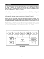
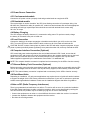
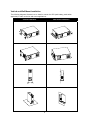
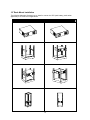
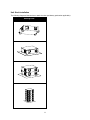
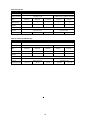
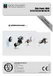
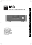
Athlon Series
True On Line, Double Conversion
Uninterruptible Power Supply
USER MANUAL
Introduction & Important Safety Instructions
Dear Customer,
Thank you for selecting a Marathon Power Uninterruptible Power Supply (UPS). You can rest assured
that you have purchased a product consistent with our reputation for quality and reliability. It will provide
you with years of protection against disruptive and costly powerdisturbances. As future needs arise, we
hope you will consider other products of ours.
Sincerely,
Marathon Power Inc.
103 W. Martin Luther King Blvd.
Los Angeles, CA 90037
Tel: 310-689-2328
Fax: 310-689-2329
_______________________________
Please take the time to read this manual!
It provides safety, installation and operating instructions that will allow you to derive the maximum
performance and service life from your UPS.
Please store this manual in a safe place!
It contains important instructions for the safe use of the UPS and for obtaining factory service
should you experience operational difficulties.
Please save or recycle the packaging materials!
They were designed to provide adequate protection from transport related damage. Since damage
sustained during transit is not covered under warranty, we recommend saving the material in case
the UPS needs to be returned for service or repair. Alternately, please recycle them.
Table of Contents
Section
Page
1. Overview . . . . . . . . . . . . . . . . . . . . . . . . . . . . . . . . . . . . . . . . . . . . . . . . . . . . . . . . . . . . . . . . . .1
2. Safety & EMC . . . . . . . . . . . . . . . . . . . . . . . . . . . . . . . . . . . . . . . . . . . . . . . . . . . . . . . . . . . . . . .2
3. Functionality . . . . . . . . . . . . . . . . . . . . . . . . . . . . . . . . . . . . . . . . . . . . . . . . . . . . . . . . . . . . . . . .4
4. Installation . . . . . . . . . . . . . . . . . . . . . . . . . . . . . . . . . . . . . . . . . . . . . . . . . . . . . . . . . . . . . . . .7
5. Operation . . . . . . . . . . . . . . . . . . . . . . . . . . . . . . . . . . . . . . . . . . . . . . . . . . . . . . . . . . . . . . . . .12
6. Alarms . . . . . . . . . . . . . . . . . . . . . . . . . . . . . . . . . . . . . . . . . . . . . . . . . . . . . . . . . . . . . . . . . . . .13
7. Software Options . . . . . . . . . . . . . . . . . . . . . . . . . . . . . . . . . . . . . . . . . . . . . . . . . . . . . . . . . . . .13
8. Care & Maintenance . . . . . . . . . . . . . . . . . . . . . . . . . . . . . . . . . . . . . . . . . . . . . . . . . . . . . . . . .14
9. Computer Interface Port . . . . . . . . . . . . . . . . . . . . . . . . . . . . . . . . . . . . . . . . . . . . . . . . . . . . . .14
10. Battery Replacement . . . . . . . . . . . . . . . . . . . . . . . . . . . . . . . . . . . . . . . . . . . . . . . . . . . . . . . . .15
11. Storage . . . . . . . . . . . . . . . . . . . . . . . . . . . . . . . . . . . . . . . . . . . . . . . . . . . . . . . . . . . . . . . . . .16
12. External Battery Packs . . . . . . . . . . . . . . . . . . . . . . . . . . . . . . . . . . . . . . . . . . . . . . . . . . . . . . .16
13. Troubleshooting . . . . . . . . . . . . . . . . . . . . . . . . . . . . . . . . . . . . . . . . . . . . . . . . . . . . . . . . . . . .17
14. Specifications . . . . . . . . . . . . . . . . . . . . . . . . . . . . . . . . . . . . . . . . . . . . . . . . . . . . . . . . . . . . .18
15. Product Warranties . . . . . . . . . . . . . . . . . . . . . . . . . . . . . . . . . . . . . . . . . . . . . . . . . . . . . . . . .22
1. Overview
For use in the most critical applications, these models are true on-line, double conversion designs
that provide a continuous, true sine-wave output with less than 3% total harmonic distortion
(THD). They allow for a wide input voltage range of +-27% and also feature power factor correction
and dual microprocessors for control of all functions.
Unique features include a ‘cold-start’ function that allows the user to power up the load(s) directly
from the UPS without the presence of utility power, a multi-function LCD display and cooling fans
that vary their speed relative to load size.
Independent input and output fuses and circuit breakers protect against overload and shortcircuits and advanced battery management extends battery life by up to 50%. 2000VA and 3000VA,
120V models also come with hard-wire terminal blocks for permanent installation.
Using the UPS with the included software and interconnecting cable allows intelligent control
of the system when linked to a host computer. (Some operating systems may require the use
of other optional software). In addition to the RS-232 function of the communication port, solid
state signalling and remote control of basic UPS functions is available.
When an overload or malfunction occurs, the UPS automatically and seamlessly transfers to bypass
mode and continues to supply the load with utility power. Upon removal of the fault condition, the
unit automatically transfers back to inverter mode once the unit has been restarted.
Block Diagram
1
EMC Statements
FCC Part 15
NOTICE: Pursuant to section 15 of the FCC rules, this product has been tested and thereby complies
with the conditions of a Class B (700-2000VA) and Class A (3000VA) digital device, which have been
established for offering sufficient protection against dangerous interference for installation in a
residential area. Installation and use of the equipment should comply with the instructions provided in
order to avoid such interference due to the amount of radio frequency energy that is radiated and
generated by the equipment. In spite of this, we cannot assure that a certain amount of interference may
not occur in some installations. If, by turning on and off, it can be deduced that your radio or television
reception is found to be influenced by harmful interference from the equipment, it is recommended that
one of the following preventive measures be used:
1. Place the receiving antenna in a separate location or orientation.
2. Ensure a greater distance is achieved between the receiver and the equipment.
3. Ensure that your equipment is connected to an outlet on a separate circuit than the receiver.
4. Contact a technician experienced with radio and TV or call tech support for further assistance.
ICES-003
This Class B Interference Causing Equipment meets all requirements of the Canadian Interference
Causing Equipment Regulations ICES–003. Cet appareil numérique de la classe B respecte toutes les
exigences du Reglement sur le matériel brouilleur du Canada.
Declaration of Conformity Request
Units labeled with a CE mark comply with the following standards and directives:
1. Harmonic Standards: EN 50091-1-1 and EN 50091-2
2. EU Directives: 73/23/EEC, Council Directive on equipment designed for use within certain voltage
limits.
93/68/EEC, Amending Directive 73/23/EEC
89/336/EEC, Council Directive relating to electromagnetic compatibility
92/31/EEC, Amending Directive 89/336/EEC relating to EMC
The EC Declaration of Conformity is available upon request for products with a CE mark.
2
IMPORTANT SAFETY INSTRUCTIONS
SAVE THESE INSTRUCTIONS
1. This Manual Contains Important Instructions that should be followed during Installation and
Maintenance of the UPS and Batteries.
2. The equipment can be operated by any individual. No previous experience is required.
3. CAUTION (UPS with Internal Batteries): Risk of electric shock - Hazardous live parts inside
this unit are energized from the battery supply even when the input AC power is disconnected.
Refer to top, rear and/or underside of the unit for cautionary markings.
4. CAUTION (No User Serviceable Parts): Risk of electric shock, do not remove cover. No user
serviceable parts inside. Refer servicing to qualified service personnel.
5. CAUTION (Non-isolated Battery Supply): Risk of electric shock, battery circuit is not isolated
from AC input; hazardous voltage may exist between battery terminals and ground. Test before
touching. Do not disconnect battery connector/s under load.
6. WARNING (Fuses): To reduce the risk of fire, replace only with the same type and rating of fuse.
7.
CAUTION (Live Heat Sink): Risk of electric shock - heatsink is live. Disconnect unit prior to servicing.
8. WARNING (Controlled Environment): Intended for installation in a controlled environment.
The maximum ambient temperature is 77°F / 25°C.
9. CAUTION: When replacing batteries, replace with the same type and number of batteries:
One Sealed lead acid battery, rated 12 V, 8.5 Ah max. Do not touch uninsulted battery terminals
10. ATTENTION (Electric Shock Hazard): Even when the unit is disconnected from the AC supply,
hazardous voltage may still exist via the battery supply. The battery supply should be disconnected
at the positive and negative termianls when the UPS needs to be serviced or the batteries replaced.
11. CAUTION: Do not dispose of batteries in a fire, as they may explode.
12. CAUTION: Do not open or damage the battery, electrolyte may be released which is harmful to
the skin and eyes.
13. CAUTION: A battery can present a risk of electric shock and high short circuit current.
The following precautions should be taken when working with batteries:
a. Remove watches, rings and other jewelry or metal objects.
b. Use only tools with insulated handles.
c. Wear rubber gloves and boots.
d. Do not lay tools or metal parts on top of batteries.
e. Disconnect charging source prior to connecting or disconnecting battery terminals.
14. To reduce the risk of electric shock, disconnect the UPS from the AC input power supply
before installing a communication interface cable. Reconnect the power cord only after
communication interconnections have been made.
15. Battery replacement should be performed or supervised by personnel with knowledge of
batteries. Keep unauthorized personnel away from the batteries.
16. CAUTION: To reduce risk of fire, use only No. 26 AWG or larger telecommunication line cord.
17. CAUTION (High Leakage Current - Ground Connection Essential): The total leakage current
for the UPS and any connected equipment shall not exceed 3.5 mA.
18. CAUTION (Size of Branch Circuit Over-current Protection): To reduce risk of fire, connect only
to a circuit capable of 35 amperes (2000VA models) and 50 amperes (3000VA models) maximum
branch circuit over-current protection in accordance with National Electric Code, ANSI/NFPA 70.
19. CAUTION (For Models with I/P Terminal Block): For 800 - 1500VA models: Use No. 10 AWG
type TW cable, trade size 3/4 in. conduit, 60°C, copper wire for input an output field wiring. For
2000/3000VA models: Use No. 8 AWG type TW cable, trade size 3/4 in. conduit, 60°C, copper
wire for input/output field wiring. Use tightening torque of 29 ft.-lbs./40Nm to secure wiring to block.
3
3. Functionality – Front Views
3.01
3.02
3.03
(not to scale)
I/P
LINE
BY PASS
I/P
LINE
Vac
BY PASS
O/P
Vac
INV
Hz
INV
O/P
INV
ON
Hz
C
BACKUP
OFF
INV
C
BACKUP
BATT
FAULT
OFF
BATT
0%
20 %
40 %
60 %
80 %
100 %
0%
20 %
40 %
60 %
80 %
100 %
ON
FAULT
0%
20 %
40 %
60 %
80 %
100 %
0%
20 %
40 %
60 %
80 %
100 %
LOAD
SELECT
LOAD
SELECT
RACK-MOUNT MODELS
3.04
LINE
3.05
BY PASS
3.06
INV
3.07
BACKUP
3.08
FAULT
I/P
O/P
INV
Vac
3.11
Hz
3.12
C
3.13
BATT
3.09
0%
20 %
40 %
60 %
80 %
100 %
0%
20 %
40 %
60 %
80 %
100 %
LOAD
3.10
TOWER MODELS
LCD DISPLAY DETAIL
3.01 “ON/TEST/SILENCE” Button
Once connected, pressing this button turns the UPS on and powers the loads. Depressing it for 1
second activates the UPS's self-test function (while in normal power mode) or silences the alarm
(while in back-up mode)
3.02 “OFF” Button
Pressing this button turns OFF the UPS and its connected loads.
3.03 “SELECT” Button
Depressing and holding the select button cycles through various LCD display modes. Modes include:
Input Voltage, Output Voltage, Input Frequency, Output Frequency and the Internal Temperature of
the UPS.
3.04 LINE:
Indicates normal operation from AC line.
3.05 BYPASS:
Indicates the UPS is in bypass mode due to a fault or manual bypass 'force' selection (See section 5).
Normal AC power will supply the load under this condition but the backup function will not operate.
3.06 INV:
This indicates that the inverter, and therefore the unit, is functioning properly.
(The opposite of BYPASS mode).
4
3.07 BACKUP:
Indicates unit is operating in backup mode during a power disturbance or loss of power.
3.08 FAULT:
Indicates an internal electronic fault.
3.09 BATTERY LEVEL BAR GRAPH:
This graph shows the charge/energy level of the battery in 20% increments.
3.10 LOAD LEVEL BAR GRAPH:
This graph shows how much of the units available capacity is being utilized in 20% increments.
3.11 INPUT (I/P) OR OUTPUT (O/P) VOLTAGE (Vac):
Pressing the SELECT button untill I/P and Vac are both lit will display the input voltage to the unit
on the display. Likewise, you may press SELECT again to show O/P and Vac to indicate the units
output voltage.
3.12 INPUT (I/P) OR OUTPUT (O/P) FREQUENCY (Hz):
Pressing the SELECT button untill I/P and Hz are both lit will display the input frequency to the
unit on the display. Likewise, you may press SELECT again to show O/P and Hz to indicate the
units output frequency.
3.13 oC (Celsius):
With this indicator lit the unit will display the internal temperature of the unit in degrees celsius.
3. Functionality – Rear Views
5
3. Functionality – Rear Views
3.19
3.21
3.21
3.14
3.15
3.16
3.17
3.18
700 / 1000 / 1500VA TOWER MODELS
3.18
NOTES:
1. Illustrations not to scale
2. All illustrations shown with NEMA receptacles. IEC and
European style receptacles are available for all models.
3.20
3. 2000 and 3000VA models shown with hardwire terminal
cover which applies to 120V models. A suitably rated IEC
socket is standard on 230V models.
2000 / 3000VA TOWER MODELS
1000 / 1500VA RM MODELS
3.20
3.15
3.16
3.18
3.17
3.21 3.14
3.19
2000 / 3000VA RM MODELS
6
3.14 SNMP/WEB INTERFACE (optional) PORT COVER
Provides access for the optional SNMP card for Ethernet connection. The SNMP kit makes the UPS
“SNMP manageable”, providing local and remote real time UPS and system status information for
networks and over the internet.
NOTE: For more information on an SNMP kit, please contact Marathon Power sales or technical support
3.15 AC OUTPUT POWER RECEPTACLES
3.16 OUTPUT CIRCUIT BREAKERS / FUSES
The circuit breaker will trip if one or both of the protected outlets are short circuited (or see a short circuit).
NOTE: Each fuse protects the outlet pair either directly to the left, or below itself.
3.17 AC INPUT POWER RECEPTACLE / CABLE
3.18 INPUT FUSE OR CIRCUIT BREAKER
The fuse will blow, OR circuit breaker will trip when the connected loads exceed the protected
receptacle's capacity.
!
CAUTION: Replace only with same fuse type and rating.
3.19 COMPUTER INTERFACE / REMOTE SIGNALLING
Provides both RS-232 and dry contact relay or solid state signals to support various operating systems.
3.20 HARDWARE INPUT / OUTPUT TERMINAL BLOCK (120V MODELS)
Allows unit to be hardwired for certain applications.
3.21 EXTERNAL BATTERY PACK CONNECTOR
For the connection of additional batteries for extended run-times.
NOTE: Use only a factory supplied or authorized connecting cable. Installation information can be
found in the user manual supplied with the battery pack.
4. Installation
4.1 Inspection
Inspect the UPS upon receipt for any visible damage. The packaging is recyclable; save it for reuse
or dispose of it properly.
NOTE: If the power consumption of the load is listed in units other than VA (e.g., Watts), use the
following calculations for conversion:
______ Watts(W) x 1.67 = ______ VA
OR
120V x ______ Amps(A) = ______ VA
4.2 Placement
Install the UPS in a protected area with adequate airflow and free of excessive dust.
!
CAUTION: Do NOT operate the UPS where the temperature and humidity is outside the specified limits.
7
4.3 Power Source Connection
4.31 Cord connected models
Connect the AC power cord to a properly wired and grounded outlet to energize the UPS.
4.32 Hardwired models
The terminal block is used to “hardwire” the UPS, thus allowing connection of input/output wiring. Use
#8 AWG wire (Twisted wire cable) for possible 3/4” conduit use and terminate each wire with appropriate
size/rating terminal lugs. Input/Output wires should be secured with terminal block screws using
29 ft.-lbs. of torque.
4.4 Battery Charging
The UPS charges its battery whenever it is connected to utility power. For optimum results, charge
the battery for at least 8 hours prior to initial use.
4.5 Load Connection
Connect the load(s) to the output receptacles or hardwire terminal block (per 4.32) on the rear of the
UPS. To use the UPS as a master ON/OFF switch, make sure all of the loads are switched ON.
!
CAUTION: Do NOT connect a laser printer or plotter to the UPS with other computer equipment. A laser
printer or plotter periodically draws significantly more power than when idle, and may overload the UPS.
4.6 Computer Interface Connection (Optional)
UPS control and power monitoring software kits are included with each UPS. If used, ensure that all
equipment is OFF and connect one end of the interface cable to the computer interface port on the back
panel of the UPS and the other end to an unused COM port on the computer. Use only kits and/or
cables supplied or approved by the manufacturer. See section 7 for additional info.
NOTE: The computer interface connection is optional and not necessary for the UPS to function correctly
4.7 External Battery Pack Connection (Optional)
Before connecting, ensure that the external bettery pack and connector cable are compatible with the UPS.
The DC bus voltages must be the same. Use only the factory supplied, external battery connection cable.
NOTE: The external battery connection is optional and not necessary for the UPS to function correctly.
4.8 Rack Mount Units
Depending on installation, 19" rack-mount applications may require the use of guide rails and/or brackets
to support the weight of the UPS. Please contact the manufacturer of your rack or enclosure to purchase
suitable mounting/installation hardware. Please see the installation diagrams that follow for guidance.
A Note on RFI (Radio Frequency Interference)
There is no guarantee that interference to a radio or TV receiver will not occur in a particular installation
If the UPS causes interference to radio or television reception, which can be determined by turining the
UPS OFF and ON, the problem may be rectified by trying one on more of the following:
• Connect the equipment to an outlet on a circuit different from that to which the receiver is connected.
• Increase the separation between the equipment and the receiver.
• Re-orient the receiving antenna.
8
Vertical and Wall-Mount Installation
The following diagrams illustrate how to install or mount the UPS (and battery packs when
applicable) in either vertical or wall-mount applications:
Vertical Installation
Wall-mount Installation
9
19” Rack-Mount Installation
The following diagrams illustrate how to install or mount the UPS (and battery packs when
applicable) in 19” rack-mount applications:
Lower Slide Rail Installation
Rear Bracket Installation
10
Unit Stack Installation
The following diagrams illustrate how to stack the units (and battery packs when applicable):
Stacking Units
11
5. Operation
5.1 Turn-ON
With the UPS connected to an A/C power source, press the ON/TEST button more than 2 seconds to
energize the UPS. It will perform a self-test each time it is switched ON. Where applicable verify the
circuit breaker on rear panel is ON.
NOTE: When switched OFF, the UPS will maintain and continue to charge the battery and also respond
to commands received through the computer interface port.
5.2 Turning Unit Off & Power Down
Press and hold the OFF button for more than one second. The 2000VA and 3000VA units require that
the rear panel breaker also be switched OFF to shut down entirely. 1000VA and 1500VA units require
input power cord to be removed from AC power source. The LCD panel displays “888.8” and the unit
will begin the power down process, which may take up to one minute.
5.3 Self-Test
Use the self-test to verify both the operation of the UPS and the condition of the battery. To perform
the self-test, press the ON/TEST button more for more than 1 second, but less than 2 seconds, under
normal power conditions. During the self-test, the UPS will operate in back-up mode.
NOTE: During the self-test, the load(s) use battery energy. The “BACKUP” icon will illuminate indicating
the UPS is supplying power.
If the UPS passes the self-test, it will return to normal on-line operation. The “BACKUP” icon will turn
OFF and the “INV” icon will illuminate.
If the UPS fails the self-test, the unit will go into BYPASS mode & may display a fault code (see
Troubleshooting), the loads are not affected. Recharge the battery overnight and perform the self-test
again. If the the self test fails again, contact tech support.
5.4 Audible Alarm Silencing
To silence the audible alarm, press the “ON/TEST” button for more than one second while the UPS
is in back-up mode.
NOTE: This function will not work when the UPS is under “Low Battery” or “Overload” conditions.
5.5 Load Bar Graph
The 5-segment display indicates the power drawn from the UPS by the load. The number of illuminated
segments represents the percentage of the UPS's rated capacity being utilized. For example, if two
segments are illuminated, the load is drawing between 20% and 40% of the UPS's rated capacity
(See section 3 for location of the display on the front panel.)
NOTE: If the UPS is overloaded, the fault code “E04“ illuminates and an alarm sounds.
(See section 6)
5.6 Battery Charge Bar Graph
The 5-segment display shows the present charge of the UPS's battery as a percentage of the battery
capacity. When all 5 segments are illuminated, the battery is fully charged. When only 1 is illuminated
the battery can supply less than 5 minutes of run time for the load.
(See section 3 for location of the display on the front panel.)
5.7 Cold Start
When the UPS is OFF and there is no utility power available or present, the cold start feature can be
used to apply power to the loads from the UPS using the battery as the power source. Press the
ON/TEST button until the UPS beeps and powers up.
12
5.8 Manual Bypass Mode
The UPS can be 'forced' into manual bypass by simultaneously pressing the ON and OFF buttons for
3 seconds. The UPS will then be in bypass mode and the load will be connected directly to the source.
The Bypass icon on the LCD display will be illuminated. This feature is used when an external maintenance bypass switch is installed and the UPS needs to be removed and/or serviced.
5.9 Shutdown Mode
In this mode, the UPS ceases supplying power to the load after battery depletion while waiting for the
return of utility power. If utility power is not restored, an external device, such as a server with software
connected to the UPS via the RS-232 interface, can command the UPS to shutdown. This is typically
done to preserve battery capacity after the proper shutdown of protected loads.
6. Alarms
6.1 “BACKUP” (slow alarm)
When in back-up mode, the UPS sounds an audible alarm. The alarm stops when the UPS returns to
LINE NORMAL operation. The alarm can be silenced by briefly pressing the “ON/TEST” button when
the ON BATTERY alarm sounds.
6.2 “LOW BATTERY” (rapid alarm)
In back-up mode, when the battery level runs low, the UPS beeps rapidly until either the UPS shuts
down due to battery depletion or it returns to LINE NORMAL operation.
NOTE: The alarm can not be silenced under this condition.
6.3 “OVERLOAD” (continuous alarm)
When the UPS is overloaded (i.e., the connected load(s) exceed the maximum rated capacity) the
UPS emits a continuous tone to warn of an overload condition, and displays the fault code “E04.”
Disconnect non-critical loads from the UPS to eliminate the overload.
6.4 “REPLACE BATTERY” (continuous alarm)
The UPS emits a continuous tone if the battery fails the self-test. See section 10 for instruction on
user battery replacement or contact tech support for assistance.
7. Software Options
7.1 Power Monitoring Software
NOTE: Please refer to the back of the software CD's holder for installation instructions. For operational
instrucions, install the software, launch the program then click HELP in the upper left corner of the
software application screen. Alternately, please visit our website to download the software User Manual.
The software is applied via the standard RS-232 interface to perform monitoring functions, as well as
as well as to implement an orderly shutdown of a computer in the event of a continuous power failure
In addition, the software displays diagnostic features, such as: input and output voltage, input and output
frequency, battery and load level, visually on your computer monitor.
The software is usable with Windows 95 or higher, Windows NT V3.5 or later, and others. Contact tech
support for more information on alternative computer OS compatible software.
7.2 Interface Kits
Included interface kit provides UPS monitoring. Each kit includes a special cable to convert status signals
from the UPS into signals which individual operating systems recognize. One end of the cable is connected to the remote port on the UPS and the other end to either the COM 1 or COM 2 port on the computer.
NOTE: Use only a factory supplied or authorized monitoring cable.
13
8. Care & Maintenance
1. Keep the unit clean and vacuum the ventilation intake periodically.
2. Wipe with a soft, damp cloth.
3. Check for loose and/or bad connections monthly.
4. Never leave the unit on an uneven surface.
5. Position the unit to allow at least 1/2” (1.3 cm) clearance between the rear panel and the wall.
6. Keep the ventilation intake open.
7. Avoid direct sunlight, rain, and high humidity.
8. Keep away from fire and extremely hot locations.
9. Do not stack anything on top of the unit.
10.The unit should not be exposed to corrosive environments.
11.Normal operating temperature is 32 to 104°F (0-40°C).
9. Computer Interface Port
1. The communication port on the back of the UPS may be connected to the host computer. The port
allows the computer to monitor the status of the UPS and, in some cases, control the operation of
the UPS.
2. Major functions include some or all of the following:
• Power disturbance notification.
• Closure of any open files prior to battery depletion.
• UPS power-up or OFF.
3. Although most computers are equipped with a connector (via COM port) to allow a link to the
communication port on the back of the UPS, a special plug-in card may be needed in the event
one is not available. Some computers may also need special software. Contact tech support for
details on various interface kits.
4. The computer interface port has the following characteristics:
• Pin 5 and 2 are open collector outputs which must be pulled up to a common reference
supply of no greater than +40 VDC.
• The transistors are capable of a maximum nonconductive load of 25 mA DC. Use pin 7 only
as the common.
• Pin 5 generates a High to Low signal when the battery inside the UPS has less than 5 minutes
back-up time left.
• Pin 2 generates a High to Low signal when the line fails.
• The UPS will shut down when a high RS-232 level is sustained on pin 6 for 0.36 seconds.
• Pin 9 is also used for RS-232 data output.
• Pin 6 is used for the RS-232 data input (RxD).
NOTES:
• Switch rating +40V,
0.15A non-inductive.
• Pin 7 should be connected to ground only.
Pin#
2
4
5
I/O
OUT
OUT
OUT
6
IN
7
IN
Function Explanation
Power failure, normally open, will become closed upon activation
Reference for pins 2 & 5 (ground)
Battery Low, normally open, closed upon activation
Remote shutdown UPS - Applying voltage (+5V ~ +12V)
to this pin for 500ms shuts the UPS down.
Reference for pin 6 (ground)
14
5 4 3 2 1
9 8 7 6
10. Battery Replacement
NOTE: Under normal operation, the battery’s life span will be 3-5 years before requiring replacement.
!
CAUTIONS:
•
•
•
•
Do NOT dispose of the batteries in a fire.
Do NOT attempt to open or dismantle the batteries.
Remove watches, rings, and other jewelry.
Use tools with insulated handles.
Marathon Power recommends that you contact our tech support for assistance with battery replacement.
To change the batteries for the Tower units:
1. Unplug the UPS unit from the AC power source and disconnect all connected equipment.
2. Disconnect the AC power cord from the UPS.
3. Remove the eight (8) cover panel securing screws located under and on the back of the unit.
4. Gently push the cover panel back until it disengages. For the 1000VA/1500VA models, the panel
slides all the way back to remove. For the 2000VA/3000VA after disengaging, the panel lifts
up and off.
5. The interconnecting wires and electronics will be exposed. Be careful not to touch any inner
components when changing the batteries.
6 . Remove the four (4) screws holding the battery retainer.
NOTE: Use caution when removing the battery retainer, the batteries are loose and may fall out.
7. Disconnect the battery cables from each battery.
8. The batteries can now be removed from the unit, and discarded appropriately.
9. Place the new batteries in the same position / direction as before and reconnect the wires.
Connect the RED wire to Positive (+) and the BLACK wire to Negative (-).
10.Follow the reverse of steps above to re-assemble the UPS.
11.Follow user manual instructions to correctly reconnect the UPS loads.
To change the batteries for the Rack Mount units (see note below for 2000VA/3000VA models):
1. Unplug the UPS unit from the AC power source and disconnect all connected equipment.
2. Disconnect the AC power cord from the UPS.
3. Remove the two (2) front panel securing screws located on the front of the unit.
4. The interconnecting wires and electronics will be exposed. Be careful not to touch any inner
components when changing the batteries.
5. Remove the two (2) securing screws and then the battery cover plate.
6. The batteries can now be removed from the unit. Slide the batteries out, disconnect and discard
appropriately.
7. Place the new batteries in the same position / direction as before and reconnect the wires.
Connect the RED wire to Positive (+) and the BLACK wire to Negative (-).
8. Follow the reverse of steps above to re-assemble the UPS.
9. Follow user manual instructions to correctly reconnect the UPS loads.
NOTE: The top cover of the 2000VA and 3000VA models will need to be removed to access the batteries.
NOTE: For proper battery disposal and recycling info, please call 800-RE-USE-Pb (800-738-7372)
15
11. Storage
11.1 Storage Conditions
Store the UPS covered, upright and in a cool, dry location, with its battery fully charged. Before
storing, charge the UPS for at least 8 hours. Remove any accessories from the unit and disconnect
any cables connected to the computer interface port to avoid draining the battery.
11.2 Extended Storage
During extended storage in environments where the ambient temperature is +5 to +86°F(-15 to +30°C ),
charge the UPS‘s battery every 6 months. During extended storage in environments where the ambient
temperature is +86 to +113°F (+30 to +45°C), charge the UPS‘s battery every 3 months.
12. External Battery Pack Installation
ATHLON SERIES RACK-MOUNT UPS + ONE RACK-MOUNT BATTERY PACK
4. Installation
12.1 Connecting The EBP's and the UPS
The EBP comes with a suitably rated interconnecting cable with a polarized plug on each end. Checking the orientation of the connectors, plug the cable into the sockets on the rear of the UPS and EBP.
RED connects to RED and BLACK connects to BLACK.
Secure the plug on either end of the cable to the UPS and the EBP using the supplied brackets. Minor
arcing (sparking) may occur briefly when connecting the EBP.
NOTE: If you are installing and connecting the UPS and EBP's for the first time, please follow the
instructions shown in the UPS User Manual as well.
NOTE: EBP's should be connected with the UPS off and completely disconnected. Do NOT connect
or disconnect EBP's while the UPS is in backup mode.
12.2 Battery Pack Charging
The UPS will charge the EBP's automatically as long as the UPS is connected to utility power, even
if the UPS is off. For optimum results, charge the UPS + EBP's for at least 24 hours prior to initial use.
16
13.Troubleshooting
Problem
Unit will not turn ON
Possible Cause
Corrective Action
ON/TEST button not pushed or
not pushed long enough
Press the ON/TEST button for more than
2 seconds to power up the UPS & load
Circuit breaker has tripped
Remove connected loads from the UPS
by unplugging equipment and resetting
the circuit breaker
Output short circuit, or UPS is
overloaded
To remove short circuited equipment or
overload, disconnect connected equipment then re-set the circuit breaker
Very low or no utility voltage
Check the AC power supply to the UPS
UPS will not turn ON or OFF Computer interface or accessory
problem. ON/TEST or OFF button
not pushed long enough
Disconnect the computer interface or
accessory. If the UPS then functions
normally, check the interface cable, the
attached computer and/or the accessory
even though line voltage is
UPS’s input circuit breaker tripped,
or circuit breaker requires activating
Remove connected loads from the UPS
by unplugging equipment and resetting
the circuit breaker
UPS beeps slowly
Normal UPS operation
None – the UPS is supporting the load
UPS does not provide
The UPS's battery is not fully recharged due to recent use or it is
near the end of its service life
Charge the battery. If the battery is near
the end of its service life, consider
replacing it, even if the fault code "E07"
has not been displayed yet
The UPS is overloaded
Check the UPS’s load display and
remove non-critical loads
Displays Fault code: E01
Output Failure
Internal fault
Do not attempt to use the UPS, turn it
OFF and have it serviced
Displays Fault code: E02
Over-temperature Condition
High ambient temp or internal fault
Power off UPS and allow to cool down.
Once cool, power up. If the problem
persists, contact technical support
Displays Fault code: E03
Output Short Circuit
Fault with connected equipment or
internal fault
Remove connected loads one-by-one
to identify. If the fault persists, contact
technical support
Displays Fault code: E04
Overload Condition
Rating/s of connected equipment
exceeds capacity of unit
Reduce load by removing some of the
connected equipment from unit
Displays Fault code: E05
Battery DC Bus Problem
Positive/Negative connections incorrect or DC bus voltage incorrect
Remove AC power from unit and reverse
the battery connections if incorrect
RED = +
BLACK =
Displays Fault code: E06
Incorrect Charge Voltage
Faulty battery charger
Contact technical support
Displays Fault code: E07
Battery Fault
Battery(ies) faulty or at the end
of their usefull life
Replace battery(ies)
UPS operates on battery
apparently present
expected back-up time
17
14. Specifications
13.1 120V Models
GENERAL
Rated Capacity:
Technology:
700VA, 1000 VA, 1500 VA, 2000 VA, 3000 VA with a power factor of 0.7
True on-line, double conversion topology with integral automatic bypass
INPUT
Phase:
Input Voltage Range:
Input Power factor:
Frequency:
AC Frequency range:
Synchronization range:
Input Current (120V):
Input Protection:
DC Bus Voltage:
Single phase plus ground
100V: 76-130V 110V: 80-138V 115V: 83.5-140V 120V: 87-140V
0.98
50 / 60 Hz Auto sensing
45 - 65 Hz
± 3Hz
700VA -5.8A, 1000VA -8.2A, 1500VA -12.4A, 2000VA -16.5A, 3000VA -25A
Circuit Breaker for overload and short protection
700VA - 24V, 1000VA - 36V, 1500VA - 48V, 2000VA - 72V, 3000VA - 96V
OUTPUT
Output Voltage:
Voltage regulation:
Voltage distortion:
Frequency regulation
Dynamic response:
Overload capacity:
Efficiency (Bypass Mode):
Efficiency (On-line Mode):
Crest Factor:
100 / 110 / 115 / 120 VAC
± 2% (700VA - 2000VA) ± 3% (3000VA)
< 5% THD with non-linear loads, < 3% THD with linear loads
± 0.25 Hz (while on battery)
± 9 % max from 100% to 20 % or from 20% to 100 % linear load
105% for 10 seconds, 130% ± 10% for 300 msec
Greater than 95%
Greater than 88%
3:1
13.2 230V Models
GENERAL
Rated power:
Technology:
700VA, 1000 VA, 1500 VA, 2000 VA, 3000 VA with a power factor of 0.7
True on-line, double conversion topology with integral automatic bypass
INPUT
Phase:
Input Voltage range:
Input Power factor:
Input Protection:
Frequency:
AC Frequency range:
Synchronization range:
Input Current (230V):
DC Bus Voltage:
Single phase plus ground
208V: 152-260V 220V: 160-276V 230V: 167-280V 240V: 174-280V
0.98
Circuit Breaker for overload and short protection
50 / 60 Hz Auto-sensing
45 - 65 Hz
± 3Hz
700VA - 3A, 1000VA - 4.4A, 1500VA - 6.5A, 2000VA - 8.7A, 3000VA - 13A
700VA - 24V, 1000VA - 36V, 1500VA - 48V, 2000VA - 72V, 3000VA - 96V
OUTPUT
Output Voltage:
Voltage regulation:
Voltage distortion:
Frequency regulation
Dynamic response:
Overload capacity:
Efficiency (Bypass Mode):
Efficiency (On-line Mode):
Crest Factor:
208 / 220 / 230 / 240 VAC
± 2%
< 5% THD with non-linear loads, < 3% THD with linear loads
± 0.25 Hz (while on battery)
± 9 % max from 100% to 20 % or from 20% to 100 % linear load
105% for 10 seconds, 130% ± 10% for 300 msec
Greater than 95%
Greater than 88%
3:1
18
13.3 All Models
ALARMS AND INDICATORS
Battery Backup:
Battery Low:
Overload:
Front Panel Display:
Display Parameters:
Communication (std):
(optional):
Slow beeping tone (approx. 0.25Hz)
Rapid beeping tone (approx. 1.00Hz)
Continuous Tone
High Intensity LCD panel
Input voltage, Output voltage, Input Frequency, Output Frequency,
Load (%), Internal Temperature (°C)
RS-232 bi-directional communication port and solid state signaling
SNMP/WEB kit for monitoring and control on a network or the internet
STANDARDS
Safety:
Emissions:
Immunity:
Conformity:
Transient Immunity (120V):
Transient Immunity (230V):
EN50091-1-1
EN50091-2 class B
EN50091-2
UL 1778, cUL 107.1, 107.2, CE
Per IEEE 62.41 (formerly IEEE 587)
Per IEEE C 61000-4-5 level 3
ENVIRONMENTAL
Ambient temperature range:
Optimum temperature range:
Storage temperature:
Cooling:
Humidity:
Elevation:
Audible noise:
+32 °F to +104°F
(+0 °C to +40 °C)
+59 °F to +77°F
(+15 °C to +25 °C)
+5 °F to +122°F
(-15 °C to +50 °C)
Forced air cooling
0-95%, non-condensing
10,000 feet max (operation), 45,000 feet (storage)
< 45 db normal and battery mode (700-1000 VA models)
< 52 db normal and battery mode (1500-3000 VA models)
19
120V Tower Models
Capacity
700VA / 490 W
Input Connection
1000VA / 700W
1500VA / 1050W
2000VA / 1400W
Hardwire Terminals
Fixed power cord
Output Connection
3000VA / 2100W
4 x NEMA 5-15R
8 x NEMA 5-15R + Hardwire Terminals
Battery Type &
Rating
Sealed, lead-acid
7.2Ah/12V
Sealed, lead-acid
7.2Ah/12V
Sealed, lead-acid
7.2Ah/12V
Sealed, lead-acid
7.2Ah/12V
Sealed, lead-acid
7.2Ah/12V
Battery Quantity
2
3
4
6
8
6 min
8 min
7 min
8 min
7 min
Backup time
(full load)
Recharge time
<8 hours to 90%
5.7 x 15.8 x 8.7
145 x 400 x 220
Dimensions ins/mm
WxDxH
Weight lbs/kg (net)
27.5 / 12.5
7.7 x 18.5 x 15.2
195 x 470 x 385
33 / 15
39.6 / 18
70.4 / 32
81.4 / 37
120V 19” Rack-mount Models (3U)
Capacity
700VA / 490 W
1000VA / 700W
1500VA / 1050W
2000VA / 1400W
3000VA / 2100W
Input Connection
Fixed power cord
Hardwire Terminals
Output Connection
4 x NEMA 5-15R
8 x NEMA 5-15R + Hardwire Terminals
Battery Type &
Rating
Sealed, lead-acid
7.2Ah/12V
Sealed, lead-acid
7.2Ah/12V
Sealed, lead-acid
7.2Ah/12V
Sealed, lead-acid
21W/12V
Sealed, lead-acid
21W/12V
Battery Quantity
2
3
4
6
8
6 min
5 min
Backup time
(full load)
6 min
8 min
Recharge time
<8 hours to 90%
19 x 15.8 x 5.2
485 x 400 x 130
Dimensions ins/mm
WxDxH
Weight lbs/kg (net)
7 min
38 / 17.3
19 x 20 x 5.2
485 x 508 x 130
44 / 20
55 / 25
20
61.6 / 28
70.4 / 32
230V Tower Models
Capacity
700VA / 490 W
1000VA / 700W
Input Connection
1500VA / 1050W
2000VA / 1400W
IEC 320 (10A)
Output Connection
Options
3000VA / 2100W
IEC 320 (16A)
4 x IEC 320 (10A)
8 x IEC 320 (10A)
4 x NEMA 5-15R
8 x NEMA 5-15R
2 x European
6 x European
Battery Type &
Rating
Sealed, lead-acid
7.2Ah/12V
Sealed, lead-acid
7.2Ah/12V
Sealed, lead-acid
7.2Ah/12V
Sealed, lead-acid
7.2Ah/12V
Sealed, lead-acid
7.2Ah/12V
Battery Quantity
2
3
4
6
8
6 min
8 min
7 min
8 min
7 min
Backup time
(Full load)
Recharge time
<8 hours to 90%
5.7 x 15.8 x 8.7
145 x 400 x 220
Dims ins/mm
WxDxH
Weight lbs/kg (net)
27.5 / 12.5
33 / 15
7.7 x 18.5 x 15.2
195 x 470 x 385
39.6 / 18
70.4 / 32
81.4 / 37
2000VA / 1400W
3000VA / 2100W
230V 19” Rack-mount Models (3U)
Capacity
700VA / 490 W
1000VA / 700W
Input Connection
1500VA / 1050W
IEC 320 (10A)
IEC 320 (16A)
Up to 12 x IEC 320 (10A)
4 x IEC 320 (10A)
Output Connection
Options
Up to 12 x NEMA 5-15R
4 x NEMA 5-15R
2 x European
6 x European, 1 x IEC 320 (16A)
Battery Type &
Rating
Sealed, lead-acid
7.2Ah/12V
Sealed, lead-acid
7.2Ah/12V
Sealed, lead-acid
7.2Ah/12V
Sealed, lead-acid
21W/12V
Sealed, lead-acid
21W/12V
Battery Quantity
2
3
4
6
8
6 min
5 min
Backup time
(Full load)
6 min
8 min
Recharge time
<8 hours to 90%
19 x 15.8 x 5.2
485 x 400 x 130
Dimensions ins/mm
WxDxH
Weight lbs/kg (net)
7 min
38 / 17.3
44 / 20
19 x 20 x 5.2
485 x 508 x 130
55 / 25
21
61.6 / 28
70.4 / 32
15. Warranty
15.1 Limited Three-Year Warranty and Exclusions
NOTE: For this warranty to be valid, completed registration information must be received within 30 days of original purchase.
Marathon Power warrants to the original purchaser, who must have properly registered the product within
30 days of purchase, and not for the benefit of anyone else that this product at the time of its sale by
Marathon Power is free of defects in materials and workmanship for three (3) years (batteries for 2 years
within the USA, Canada and Mexico, otherwise 1 year) from the original purchase date. Marathon Power
will correct such defects by repair or replacement, at its option, if within such three year period the product is
returned prepaid and all warranty claim instructions are followed. This warranty excludes labor for removal
or reinstallation of this product. This warranty is void if this product is installed improperly or in an improper
environment, overloaded, misused, opened, abused, or altered in any manner, or is not used under normal
operating conditions or not in accordance with all labels or instructions. There are no other or implied
warranties of any kind, including merchantability and fitness for a particular purpose, but if any implied
warranty is required by the applicable jurisdiction, the duration of any such implied warranty, including
merchantability and fitness for a particular purpose, is limited to three years. Marathon Power is not liable
for incidental, indirect, special or consequential damages, including damage to, or loss of use of, any
equipment, lost sales or profits or delay or failure to perform this warranty obligation.
15.2 Limitations & Claims
This warranty does not cover any Marathon Power UPS or any properly connected electronic equipment
which has been improperly installed, overloaded, abused or altered in any manner, or is not used under
normal operating conditions, or in accordance with any labels or instructions, and does not cover any
damage to properly connected electronic equipment resulting from a cause other than a “surge”.
Damage caused by failure to provide a suitable installation environment for the product (including, but
not limited to, lack of a good ground) will not be covered by this warranty. This warranty does not apply
to damage caused by direct lightning strikes, or damage caused by electrical disturbances that exceed
published product specifications. These products are intended to limit the maximum amplitude of transient
voltage surges on power lines to specified values. They are not intended to function as surge arrestors.
The UPS is intended to be installed on the load side of the service entrance and has been tested to verify
that transient voltage surges are limited when subject to non-repetitive transient voltage surge events. This
warranty excludes any incidental, indirect, special or consequential damages, including without limitation,
labor for removal or reinstallation of the Marathon Power UPS or any connected electronic equipment,
data loss or alteration loss of equipment use, lost sales or profits and any such damages for delay or
failure to perform this warranty obligation. This warranty is in lieu of and excludes all implied warranties
of merchantability or fitness for use. In addition, the warranty does not cover restoration of lost data and
reinstallation of software. Some states may not allow the exclusion or limitation of incidental or consequential
damages or other remedies, so the above exclusions or limitations may not apply to you.
Take the following stps to file a warranty claim: Contact us at Marathon Power, Inc., Attn: Returns, 2538 E.
54th Street, Huntington Park, California 90255 or call (310) 689-2328 within 30 days of the occurrence. Be
prepared to provide detailed information about the event, any damage, the UPS model number, purchase
date and location. You will then be provided with a Return Authorization Number (RAN), and be instructed
to forward your proof of purchase (receipt), an explanation of the event and your UPS. If Marathon Power
determines that the damage was due to a “surge”, we may request that all connected equipment be submitted
for evaluation. Marathon Power is not responible for shipping costs. In the event that the equipment has
been damaged by a “surge” Marathon Power will reimburse you for repair or replacement at fair market
value (on a pro rata basis) as indicated by the respective amounts above. The warranty coverage is above
and beyond, only to the extent needed, of that provided by any other source, including but not limited to
any connected equipment coverage, any manufacturer’s warranty or insurance policy. To receive payment
for repair to damage due to a “surge,” the original purchaser should (upon prior approval from Marathon
Power) have such equipment repaired by an authorized service center of such equipment’s manufacturer.
The original purchaser will submit a repair bill along with a statement from the repair facility documenting
the nature of the damage and how it was sustained to said equipment.
22
Copyright Marathon Power, Inc. 2007
www.marathon-power.com
athlonuserman2007