1
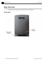
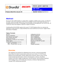
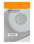
ShoreTel IP Phone 930D Base Station and Repeater User Guide May 2013 Legal Notices Document and Software Copyrights Copyright © 1998-2013 by ShoreTel Inc., Sunnyvale, California, USA. All rights reserved. Printed in the United States of America. Contents of this publication may not be reproduced or transmitted in any form or by any means, electronic or mechanical, for any purpose, without prior written authorization of ShoreTel, Inc. ShoreTel, Inc. reserves the right to make changes without notice to the specifications and materials contained herein and shall not be responsible for any damage (including consequential) caused by reliance on the materials presented, including, but not limited to typographical, arithmetic or listing errors. Trademarks and Patents ShoreTel, ShoreTel (and logo), ControlPoint, Brilliantly Simple, Brilliantly Simple Communication, ShoreCare, ShoreGear, ShorePhone, and ShoreWare are registered trademarks of ShoreTel, Inc. in the United States and/or other countries. The ShoreTel logo is a trademark of ShoreTel, Inc. in the United States and/or other countries. All other copyrights and trademarks herein are the property of their respective owners. The ShoreTel Mobility solution is covered by patents as listed at http://www.shoretel.com/about/patents.html. Version Information ShoreTel IP Phone 930D Base Station and Repeater User Guide Part Number: 800-1806-01 Date: May 2013 Company Information ShoreTel, Inc. 960 Stewart Drive Sunnyvale, California 94085 USA +1.408.331.3300 +1.408.331.3333 (fax) www.shoretel.com 2 Base Station and Repeater User Guide ShoreTel IP Phone 930D Contents Before You Start . . . . . . . . . . . . . . . . . . . . . . . . . . . . . . . . . . . . . . . . . . . . . . . . . . . . . . . . . . . .5 About This Book . . . . . . . . . . . . . . . . . . . . . . . . . . . . . . . . . . . . . . . . . . . . . . . . . . . . . . . . . . . . . Organization . . . . . . . . . . . . . . . . . . . . . . . . . . . . . . . . . . . . . . . . . . . . . . . . . . . . . . . . . . . . Conventions . . . . . . . . . . . . . . . . . . . . . . . . . . . . . . . . . . . . . . . . . . . . . . . . . . . . . . . . . . . . Related Documents . . . . . . . . . . . . . . . . . . . . . . . . . . . . . . . . . . . . . . . . . . . . . . . . . . . . . . . . . . Chapter 1 5 5 5 6 Using the Base Unit . . . . . . . . . . . . . . . . . . . . . . . . . . . . . . . . . . . . . . . . . . . . .7 Unpacking the Box . . . . . . . . . . . . . . . . . . . . . . . . . . . . . . . . . . . . . . . . . . . . . . . . . . . . . . . . . . . 7 Base Overview . . . . . . . . . . . . . . . . . . . . . . . . . . . . . . . . . . . . . . . . . . . . . . . . . . . . . . . . . . . . . . 8 Front View . . . . . . . . . . . . . . . . . . . . . . . . . . . . . . . . . . . . . . . . . . . . . . . . . . . . . . . . . . . . . . 8 Rear View . . . . . . . . . . . . . . . . . . . . . . . . . . . . . . . . . . . . . . . . . . . . . . . . . . . . . . . . . . . . . . 9 Understanding Base Basics . . . . . . . . . . . . . . . . . . . . . . . . . . . . . . . . . . . . . . . . . . . . . . . . . . . . 9 Readying the Base for Use . . . . . . . . . . . . . . . . . . . . . . . . . . . . . . . . . . . . . . . . . . . . . . . . . . . 10 Installing the Base . . . . . . . . . . . . . . . . . . . . . . . . . . . . . . . . . . . . . . . . . . . . . . . . . . . . . . . . . . 11 Resetting the Base to Factory Defaults . . . . . . . . . . . . . . . . . . . . . . . . . . . . . . . . . . . . . . . . . . 12 Monitoring a Base with the LED Indicator . . . . . . . . . . . . . . . . . . . . . . . . . . . . . . . . . . . . . . . . 12 Chapter 2 Using the Repeater Unit . . . . . . . . . . . . . . . . . . . . . . . . . . . . . . . . . . . . . . . . . 13 Unpacking the Box . . . . . . . . . . . . . . . . . . . . . . . . . . . . . . . . . . . . . . . . . . . . . . . . . . . . . . . . . . Repeater Overview . . . . . . . . . . . . . . . . . . . . . . . . . . . . . . . . . . . . . . . . . . . . . . . . . . . . . . . . . Front View . . . . . . . . . . . . . . . . . . . . . . . . . . . . . . . . . . . . . . . . . . . . . . . . . . . . . . . . . . . . . Rear View . . . . . . . . . . . . . . . . . . . . . . . . . . . . . . . . . . . . . . . . . . . . . . . . . . . . . . . . . . . . . Repeater Basics . . . . . . . . . . . . . . . . . . . . . . . . . . . . . . . . . . . . . . . . . . . . . . . . . . . . . . . . . . . . Powering the Repeater . . . . . . . . . . . . . . . . . . . . . . . . . . . . . . . . . . . . . . . . . . . . . . . . . . . . . . Connecting the AC Adapter . . . . . . . . . . . . . . . . . . . . . . . . . . . . . . . . . . . . . . . . . . . . . . . . Using a PoE Wire Adapter to Power the Repeater . . . . . . . . . . . . . . . . . . . . . . . . . . . . . . Registering a Repeater to a Base . . . . . . . . . . . . . . . . . . . . . . . . . . . . . . . . . . . . . . . . . . . . . . Installing the Repeater . . . . . . . . . . . . . . . . . . . . . . . . . . . . . . . . . . . . . . . . . . . . . . . . . . . . . . . Restoring a Repeater to Factory Defaults . . . . . . . . . . . . . . . . . . . . . . . . . . . . . . . . . . . . . . . . Monitoring a Repeater with the LED Indicator . . . . . . . . . . . . . . . . . . . . . . . . . . . . . . . . . . . . . Chapter 3 14 14 14 15 15 16 16 17 18 18 19 19 Troubleshooting . . . . . . . . . . . . . . . . . . . . . . . . . . . . . . . . . . . . . . . . . . . . . . . 21 Troubleshooting for the Base Station . . . . . . . . . . . . . . . . . . . . . . . . . . . . . . . . . . . . . . . . . . . . 21 Troubleshooting for the Repeater . . . . . . . . . . . . . . . . . . . . . . . . . . . . . . . . . . . . . . . . . . . . . . 22 Accessing Site Survey Mode . . . . . . . . . . . . . . . . . . . . . . . . . . . . . . . . . . . . . . . . . . . . . . . 24 ShoreTel IP Phone 930D Base Station and Repeater User Guide 3 Table of Contents 4 Base Station and Repeater User Guide ShoreTel IP Phone 930D Before You Start This preface contains the following topics: About This Book on page 5 Related Documents on page 6 About This Book This book is intended for those who install, administer, or use the ShoreTel IP Phone 930D. It describes the features of the base station unit and the repeater unit. This document should be used in conjunction with the ShoreTel IP Phone 930D Planning and Installation Guide. Organization This document is divided into the following chapters: Chapter 1, Using the Base Unit on page 7, describes how to install and use the base station. Chapter 2, Using the Repeater Unit on page 13, describes how to install and use the repeater. Chapter 3, Troubleshooting on page 21, describes how to troubleshoot issues with the components. Conventions The following typographical marking conventions are used in this document. Marking Meaning Bold Names of interface objects, such as buttons and menus. Blue Cross references with hyperlinks. Click the blue text to go to the indicated section. All chapters have a list of section links on the first page. Note: Table of Contents entries are also links, but they are not shown in blue. ShoreTel IP Phone 930D Base Station and Repeater User Guide 5 Before You Start Related Documents Related Documents The following documents are also available: 6 ShoreTel IP Phone 930D Planning and Installation Guide ShoreTel IP Phone 930D Handset User Guide Base Station and Repeater User Guide ShoreTel IP Phone 930D CHAPTER 1. Using the Base Unit This chapter describes how to set up and use the IP930D base unit and contains these main topics: Unpacking the Box on page 7 Base Overview on page 8 Understanding Base Basics on page 9 Readying the Base for Use on page 10 Installing the Base on page 11 Resetting the Base to Factory Defaults on page 12 Monitoring a Base with the LED Indicator on page 12 Unpacking the Box Make sure that all of these items are included in the base unit package: 1 x IP930D base 1 x base charging stand 1 x printed Safety, Warranty, and Regulatory Information sheet 2 x wall mounting screws and anchors ShoreTel IP Phone 930D Base Station and Repeater User Guide 7 1 Using the Base Unit Base Overview Base Overview The illustrations below show the front view and back view of the IP930D base. Front View 8 Base Station and Repeater User Guide ShoreTel IP Phone 930D 1 Using the Base Unit Rear View Rear View Understanding Base Basics Bases are the gateway between the IP network and IP930D handsets. Bases are powered by a Power-over-Ethernet (PoE) connection. Bases can be used in stand-alone- or multicell-mode. If more than four handsets are needed in a system, the multicell mode is required to synchronize bases and maximize performance. Each base can support up to four IP930D handsets. Bases come in two versions: A version for North America, and a second for Europe, Australia, and New Zealand. The IP930D handset detects the frequencies used by the base and adapts automatically. For more information, see the ShoreTel IP Phone 930D Planning and Installation Guide. ShoreTel IP Phone 930D Base Station and Repeater User Guide 9 1 Using the Base Unit Readying the Base for Use Readying the Base for Use 1. Prepare the configuration files for the base and upload them to the FTP server. See the ShoreTel IP Phone 930D Planning and Installation Guide for instructions on how to prepare these files. 2. If the base will be wall mounted, remove the base stand from the bottom of the base by pressing the area shown and pulling downward. 3. Plug the Ethernet cable downward into the jack and route the cable through the cable guide so the cable exits near the bottom of the base. WARNING! Do not unplug the Ethernet cable until the LED indicator stops fast flashing red (500 mS on/500 mS off); unplugging the cable while the LED indicator is fast flashing red can permanently damage the base. 10 Base Station and Repeater User Guide ShoreTel IP Phone 930D 1 Using the Base Unit Installing the Base When the Ethernet cable is attached, the base powers up and downloads configuration files from the specified FTP server, after which the base can be managed using ShoreTel IP930D Manager. Note Option 156 must be enabled and the ftpserver parameter set so that the base can locate and load the required configuration files. Refer to the ShoreTel IP Phone 930D Planning and Installation Guide for more information. The first time the base is plugged in, the process can take up to 10 minutes. The base LED indicator will stop flashing red or green when the process is complete. Installing the Base To mount the base on a wall, use the provided screws, or use bolts with a 6-10 mm head and a shaft that is less than 4 mm in diameter. Install screws or bolts with centers separated by 60 mm. Here are some guidelines for installing bases: Bases should be mounted as high on a wall as possible and away from large metal objects or building structures that can block their signal. Do not mount bases near electrical appliances such as microwave ovens or other radio frequency sensitive or generating equipment such as computers. Bases must be mounted with at least one meter of separation between devices. All bases must all be installed on the same subnet. For more guidance on where to locate bases when installing your system, see the ShoreTel IP Phone 930D Planning and Installation Guide. ShoreTel IP Phone 930D Base Station and Repeater User Guide 11 1 Using the Base Unit Resetting the Base to Factory Defaults Resetting the Base to Factory Defaults To return a base to its factory defaults, follow this procedure: 1. Plug in the base and wait until the LED indicator starts flashing green. 2. Press and then hold the reset button on the back of the base for at least 10 seconds, or until the LED indicator turns off. The base restarts using its factory defaults. WARNING! Never unplug a base or perform any type of reset on a base whose LED indicator is fast flashing red (500 mS on/500 mS off); doing so can permanently damage the base. A fast red flash means that firmware in the unit is being upgraded. Monitoring a Base with the LED Indicator The base has an LED indicator on the front that can be used to monitor the base’s status. Additional information on the base status is available using ShoreTel IP930D Manager. LED State Description Off No power. Two red flashes followed by flashing green (1 sec on/1 sec off) Base is starting. Winking green (800 mS on/200 mS off) Base has started running but has not yet synchronized to a master (multicell only). Solid green Unit is operating normally and is synchronized to a master. Winking red (800 mS on/200 mS off) No Ethernet. Fast flashing red (500 mS on/500 mS off) Unit is upgrading firmware. (Do not remove power.) 12 Flashing red/green (1 S red/1 S green) Registration enabled. Solid red Critical error. Base Station and Repeater User Guide ShoreTel IP Phone 930D CHAPTER 2. Using the Repeater Unit This chapter describes how to set up and use the IP930D repeater unit and contains these main topics: Unpacking the Box on page 14 Repeater Overview on page 14 Repeater Basics on page 15 Powering the Repeater on page 16 Registering a Repeater to a Base on page 18 Installing the Repeater on page 18 Restoring a Repeater to Factory Defaults on page 19 Monitoring a Repeater with the LED Indicator on page 19 ShoreTel IP Phone 930D Base Station and Repeater User Guide 13 2 Using the Repeater Unit Unpacking the Box Unpacking the Box Make sure that all of these items are included in your repeater package: 1 x IP930D repeater 1 x AC adapter with plug adapters 1 x printed Safety, Warranty, and Regulatory Information sheet 1 x wall mounting screw and anchor Repeater Overview The illustrations below show the front view and back view of the IP930D repeater. Front View 14 Base Station and Repeater User Guide ShoreTel IP Phone 930D 2 Using the Repeater Unit Rear View Rear View Repeater Basics Repeaters are used to extend the operating range of IP930D handsets beyond the coverage area of the base station. To deliver optimal service, IP930D handsets will automatically connect to the base or repeater with the strongest signal. Before the repeater is installed, it must be registered to a base station. Up to four repeaters can be registered to a base station. Up to three repeaters can be daisy chained to provide coverage (but doing so may introduce delays and Y-branches are not supported). Repeaters can be used to extend coverage in all directions, including vertically (to cover several floors in a building). If repeaters are positioned correctly, the mobile handset will automatically switch from cell to cell with no noticeable interruption. Correct positioning means overlapping the coverage area of the base station or other repeaters. ShoreTel IP Phone 930D Base Station and Repeater User Guide 15 2 Using the Repeater Unit Powering the Repeater Powering the Repeater Repeaters require one of these for power: A non-switched AC outlet (100-240V 50/60hz) within 2 meters of the repeater. A PoE wire adapter and Linksys POES5 5-volt PoE splitter for use with a powered Ethernet connection. Connecting the AC Adapter Follow these steps: 1. Choose the AC power plug that matches the AC outlet in your country or region. 2. Insert the AC power plug into the AC adapter; slide until it locks in place. 3. Plug the AC adapter cable into the modular adapter jack on the rear of the repeater. If the location where you would like to install in the repeater does not have a nearby AC outlet, use a PoE wire adapter instead of AC power. See Using a PoE Wire Adapter to Power the Repeater on page 17. WARNING! Do not use extension cables to lengthen the AC adapter cable; doing so can cause the repeater to malfunction. 16 Base Station and Repeater User Guide ShoreTel IP Phone 930D 2 Using the Repeater Unit Using a PoE Wire Adapter to Power the Repeater Using a PoE Wire Adapter to Power the Repeater If you need to position the repeater in a location that does not provide a nearby AC outlet, you can use a PoE wire adapter and a Linksys POES5 5-volt PoE splitter with a powered Ethernet connection to power the repeater. Use the Linksys splitter to provide power only; do not use the Ethernet cable provided by the splitter. See the illustration below. Splitter Ethernet cable (do not use) PoE wire adapter Linksys splitter Repeater Powered Ethernet cable plugs in here ShoreTel IP Phone 930D Base Station and Repeater User Guide 17 2 Using the Repeater Unit Registering a Repeater to a Base Registering a Repeater to a Base Refer to the ShoreTel IP Phone 930D Planning and Installation Guide for additional information. 1. Configure the bases in your system to permit repeaters to register, and to assign synchronization relationships for each repeater. 2. From the Base Security page in ShoreTel IP930D Manager, enable registration on the base with which you would like to register. Enable registration on only one base at a time; otherwise, the repeater may attempt to register with the wrong base and delay the registration process. 3. Provide power to the repeater by using AC power, or use a PoE wire adapter and splitter (see Using a PoE Wire Adapter to Power the Repeater on page 17). Power the repeater in a location that is near to the base to ensure a good signal. 4. Check that the LED indicator on the front of the repeater begins double-flashing green. If this is not the case, press and hold the reset button on the back of the repeater until the LED indicator turns red and then release the button. The LED indicator begins double-flashing green. 5. Within one minute, the LED indicator turns steady green, indicating that the repeater has registered with the base. Repeat the above process for all of the repeaters you wish to register with this base. Be sure to disable registration from ShoreTel IP930D Manager before proceeding to the next base. Installing the Repeater Here are some guidelines for installing repeaters: 18 Repeaters should be mounted as high on a wall as possible and away from large metal objects or building structures that can block their signal. Repeaters must be located within six feet of an AC outlet; otherwise, use a PoE wire adapter and splitter for power. See Using a PoE Wire Adapter to Power the Repeater on page 17. Repeaters must be located close enough to the base or repeater to which they are synchronized to provide a signal level between about -65 and -75 dBm. (A value of -70 dBm or better is recommended). Do not mount repeaters near electrical appliances or other radio frequency generating equipment, such as microwaves or computers. Repeaters must be mounted with at least one meter of separation between devices. Do not use an AC outlet that can be switched off. Base Station and Repeater User Guide ShoreTel IP Phone 930D 2 Using the Repeater Unit Restoring a Repeater to Factory Defaults Do not use a cable extender to lengthen the AC adapter’s cable; doing so may cause the repeater to malfunction. A single screw or bolt (provided) with a 6-10 mm head and a shaft that is less than 4 mm in diameter can be used to mount the unit on the wall. For information more information, see the ShoreTel IP Phone 930D Planning and Installation Guide. Restoring a Repeater to Factory Defaults While the repeater is powered, press and hold the reset button on the back of the unit for 3 seconds or until the repeater’s LED indicator turns red. The repeater restarts in a factory default state. Monitoring a Repeater with the LED Indicator The repeater has an LED indicator on the front that can be used to monitor the repeater’s performance. Additional information on the repeater status is available using ShoreTel IP930D Manager. LED State Description Off No power. Slow flashing green (400 mS on/250 mS off) Searching for fixed part (base or repeater). Double flashing green (900 mS on/200 mS off/200 mS on/200 mS off repeated) Searching for fixed part in registration mode or performing registration procedures. Steady green (occasional red flashes) Repeater is synchronized to its master and operating properly. Red flashes indicate traffic is passing through the repeater. Alternating red/green flashing (200 mS red/ Repeater is in recovery mode and cannot find base or 200 mS green) RPN allocation error. Steady red ShoreTel IP Phone 930D Critical error. Base Station and Repeater User Guide 19 2 Using the Repeater Unit 20 Base Station and Repeater User Guide Monitoring a Repeater with the LED Indicator ShoreTel IP Phone 930D CHAPTER 3. Troubleshooting This chapter contains the following topics: Troubleshooting for the Base Station on page 21 Troubleshooting for the Repeater on page 22 Troubleshooting for the Base Station Problem: The LED indicator on the base is fast flashing red (500 mS on/500 mS off) and does not show steady green after the Ethernet cable is plugged in. Solution: The LED indicator on the base fast flashes red during firmware upgrades, which may occur when the base is first powered on. The upgrade can take up to 10 minutes to complete. WARNING! Never unplug a base while the LED indicator is fast flashing red or the base may be permanently damaged. Problem: The LED indicator on the base is flashing green (1 second on/1 second off) and does not show steady green after the Ethernet cable is plugged in. Solution: The base is unable to obtain an IP address from a DHCP server. Check that a DHCP server is available by plugging a laptop or other device into the Ethernet cable. Problem: The LED indicator on the base is winking green (800 mS on/200 mS off) and never becomes steady green. ShoreTel IP Phone 930D Base Station and Repeater User Guide 21 3 Troubleshooting Troubleshooting for the Repeater Solution: The base is having difficulty synchronizing with other bases. In some cases this can take up to 10 minutes. If the issue extends longer, it may indicate that the base cannot find a free DECT channel to use to communicate with other bases. Check for interfering DECT or other RF devices near the base. Another cause may be an error in the configuration files for this base. Re-check the configuration files for the base, following the guidelines provided in the ShoreTel IP Phone 930D Planning and Installation Guide. Problem: The LED indicator on the base is winking red (800 mS on/200 mS off). Solution: The base does not detect an Ethernet connection. Check the connection between the base and the Ethernet switch. Problem: The LED indicator on the base is solid red Solution: This indicates a critical error. Try power cycling the base: Unplug the Ethernet connection to the base to remove power for a few seconds, then reconnect. If the issue is not resolved, the base has encountered a non-recoverable error and needs to be replaced. Troubleshooting for the Repeater Problem: The LED indicator on the repeater is slow flashing green (400 mS on/250 mS off) and never becomes steady green after installation. Solution: The repeater is having trouble connecting to either the base to which it is registered or to the repeater from which it receives synchronization. First try power cycling the repeater to resolve the issue. If the issue is not resolved, follow the procedure below (Accessing Site Survey Mode on page 24) to access site survey mode on the handset. Then check that the signal level from the hosting base or repeater is between -65 and -75 dBm when measured near the repeater with the flashing green LED. (A value of -70 dBm or better is recommended.) If the signal level is outside of this range, the repeater needs to be relocated to synchronize properly. Problem: The LED indicator on the repeater is alternating red and green flashing. Solution: The repeater is in the recovery mode and cannot find a base or cannot allocate an RPN. Load the project file for the installation into the ShoreTel IP930D Configuration Tool and check the following: Check for typographical errors in the IPEI values for each repeater. Check that the synchronization source for every repeater is correct. Check that every repeater is associated with the correct base. You can check each of these items by selecting a repeater and viewing properties in the right-hand pane of the Configuration Tool. Alternatively, you can print the installation summary to check these items. See the ShoreTel IP Phone 930D Planning and Installation Guide for assistance. 22 Base Station and Repeater User Guide ShoreTel IP Phone 930D 3 Troubleshooting Troubleshooting for the Repeater The symptom (LED indicator flashing red/green) may also indicate that the repeater cannot find a free DECT channel to use to communicate with the hosting base or repeater. Check for interfering DECT devices or other RF devices near the repeater and hosting base. Problem: There are no AC outlets near where the repeater should be located. Solution: Use a PoE wire adapter instead of AC power. See Using a PoE Wire Adapter to Power the Repeater on page 17 for more information. WARNING! Do not use extension cables to lengthen the AC adapter cable; doing so can cause the repeater to malfunction. Problem: A beep is heard about every 3 seconds when on a call. Solution: Debug mode on a repeater has been accidently activated. Follow these steps: 1. While on a call, access the site survey mode on the beeping handset. See Accessing Site Survey Mode on page 24 for the procedure. 2. In this mode, detect the RPN of the repeater that is in debug mode (it will be the left-most RPN on the site survey screen). 3. In the Manage Bases page of ShoreTel IP930D Manager, obtain the IPEI for the repeater that you identified by RPN in the previous step. 4. Find the matching repeater by looking at the IPEI on the hardware label. When there are no active calls on this repeater (the status LED is steady green without red flashes), press the reset button on the repeater for more than 20 seconds to turn off the beeping. ShoreTel IP Phone 930D Base Station and Repeater User Guide 23 3 Troubleshooting Accessing Site Survey Mode Accessing Site Survey Mode 1. Press and hold the Menu button on the IP930D handset for more than 3 seconds. The Settings menu appears. 2. Enter *service* (or *7378423*). 3. Turn on the site survey mode from the menu. An overlay displays the RPN of the base or repeater the handset is connected to (left-most) and any other base or repeaters it can see. Also shown is the RSSI (received signal strength indicator) for the base or repeater to which the handset is connected. Note The RPN is a unique identifier assigned to each base and repeater in the system. RPN assignments are included in the Installation Summary generated by the ShoreTel IP930D Configuration Tool during installation. 4. Press End/Power to exit the Settings menu. 24 Base Station and Repeater User Guide ShoreTel IP Phone 930D