1
INSTALLER: LEAVE THIS MANUAL WITH THE APPLIANCE. CONSUMER: RETAIN THIS MANUAL FOR FUTURE REFERENCE. NEVER LEAVE CHILDREN OR OTHER AT RISK INDIVIDUALS ALONE WITH THE APPLIANCE. 1 INSTALLATION AND OPERATING INSTRUCTIONS CERTIFIED UNDER CANADIAN AND AMERICAN NATIONAL STANDARDS: CSA 2.22, ANSI Z21.50 FOR VENTED GAS FIREPLACES. BCDV36CFNTR, BCDV36CFGN-1 CERTIFIED FOR CANADA AND UNITED STATES USING ANSI/CSA METHODS. NATURAL GAS MODEL SAFETY INFORMATION ! BCDV36CFPTR, BCDV36CFGP-1 WARNING If the information in these instructions are not followed exactly, a fire or explosion may result causing property damage, personal injury or loss of life. PROPANE GAS MODEL - Do not store or use gasoline or other flammable vapors and liquids in the vicinity of this or any other appliance. - WHAT TO DO IF YOU SMELL GAS: • Do not try to light any appliance. • Do not touch any electrical switch; do not use any phone in your building. • Immediately call your gas supplier from a neighbour’s phone. Follow the gas supplier’s instructions. • If you cannot reach your gas supplier, call the fire department. - Installation and service must be performed by a qualified installer, service agency or the supplier. This appliance may be installed in an aftermarket, permanently located, manufactured home (USA only) or mobile home, where not prohibited by local codes. This appliance is only for use with the type of gas indicated on the rating plate. This appliance is not convertible for use with other gases, unless a certified kit is used. ! WARNING HOT GLASS WILL CAUSE BURNS. DO NOT TOUCH GLASS UNTIL COOLED. NEVER ALLOW CHILDREN TO TOUCH GLASS. Wolf Steel Ltd., 24 Napoleon Rd., Barrie, ON, L4M 0G8 Canada / 103 Miller Drive, Crittenden, Kentucky, USA, 41030 Phone (705)721-1212 • Fax (705)722-6031 • www.continentalfireplaces.com • [email protected] $10.00 1.24B W415-1136 / 07.11.12 2 TABLE OF CONTENTS 1.0 2.0 3.0 INSTALLATION OVERVIEW INTRODUCTION 3 4 2.1 2.1.1 2.2 2.3 2.4 5 5 5 6 7 VENTING 3.1 3.2 3.3 3.3.1 3.3.2 3.4 3.5 3.6 3.7 3.8 3.9 3.10 4.0 5.0 6.0 7.0 8.0 9.0 DIMENSIONS BCDV36CF / BCDV36CFG GENERAL INSTRUCTIONS GENERAL INFORMATION RATING PLATE INFORMATION VENTING LENGTHS AND COMPONENTS TYPICAL VENT INSTALLATIONS SPECIAL VENT INSTALLATIONS PERISCOPE TERMINATION CORNER TERMINATION VENT TERMINAL CLEARANCES VENT APPLICATION FLOW CHART DEFINITIONS ELBOW VENT LENGTH VALUES TOP EXIT HORIZONTAL TERMINATION REAR EXIT HORIZONTAL TERMINATION TOP OR REAR EXIT VERTICAL TERMINATION 7 8 9 11 11 11 12 13 13 14 14 16 18 PRE-INSTALLATION PREPARATION 20 4.1 4.2 4.3 4.4 20 21 21 21 REMOVING THE VALVE ACCESS DOOR AND TOP DOOR TRIM DOOR OPERATION REAR EXIT TOP VENT INSTALLATION 22 5.1 5.2 5.3 5.4 5.4.1 5.4.2 5.4.3 5.5 5.5.1 5.5.2 5.6 5.6.1 5.7 5.8 5.9 22 23 23 24 24 25 26 26 26 26 27 28 29 29 30 WALL AND CEILING PROTECTION HORIZONTAL INSTALLATION VERTICAL INSTALLATION USING FLEXIBLE VENT COMPONENTS HORIZONTAL AIR TERMINAL INSTALLATION VERTICAL AIR TERMINAL INSTALLATION APPLIANCE VENT CONNECTION USING RIGID VENT COMPONENTS HORIZONTAL AIR TERMINAL INSTALLATION EXTENDED HORIZONTAL AND CORNER TERMINAL INSTALLATION VERTICAL THROUGH EXISTING CHIMNEY VERTICAL AIR TERMINAL INSTALLATION MOBILE HOME INSTALLATION GAS INSTALLATION OPTIONAL WALL SWITCH EXCLUDING BCDV36CFG FRAMING 31 6.1 6.2 6.2.1 6.3 6.3.1 6.3.2 6.3.3 6.3.4 6.4 6.4.1 6.4.2 6.5 6.6 32 33 34 35 35 36 36 37 38 38 39 40 40 INSTALLING STAND-OFFS MINIMUM FRAMING DIMENSIONS STEEL HEADER INSTALLATION FOR CLEAN FACE SURROUND MINIMUM ENCLOSURE CLEARANCES REAR VENT ENCLOSURE TOP VENT ENCLOSURE ALCOVE ENCLOSURE CLEAN FACE SURROUND MINIMUM ENCLOSURE CLEARANCES CLEAN FACE SURROUND FRAMING AND FINISHING FINISHED FLOOR INSTALLATION HEARTH INSTALLATION ALCOVE FRAMING MINIMUM MANTEL CLEARANCES FINISHING 41 7.1 7.2 41 42 DOOR INSTALLATION & REMOVAL CLEAN FACE TRIM KIT INSTALLATION BGD36CF FINISHING 43 8.1 8.2 8.3 8.4 8.5 43 44 44 44 44 LOG PLACEMENT GLOWING EMBERS CHARCOAL EMBERS LOGO PLACEMENT OPTIONAL ROCK KIT BCDV36CFG FINISHING 9.1 GLASS BURNER INSTALLATION 45 45 10.0 OPTIONAL BLOWER INSTALLATION 11.0 WIRING DIAGRAM 47 11.1 11.2 11.3 47 48 49 10.1 12.0 ACCESSING THE BLOWER BCDV36CFG LIGHT SWITCH BCDV36CFG BURNER SWITCH RECEPTACLE WIRING DIAGRAM 46 46 OPERATION 49 12.1 12.2 12.3 49 50 51 BCDV36CF LIGHT OPERATION BCDV36CF BCDV36CFG NOTE: Changes, other than editorial, are denoted by a vertical line in the margin. W415-1136 / 07.11.12 3 13.0 14.0 15.0 16.0 17.0 18.0 19.0 ADJUSTMENTS 52 13.1 PILOT BURNER ADJUSTMENT 13.2 VENTURI ADJUSTMENT 13.2.1 BCDV36CF VENTURI ADJUSTMENT 13.2.2 BCDV36CFG VENTURI ADJUSTMENT 13.3 BCDV36CF FLAME CHARACTERISTICS 13.4 BCDV36CFG FLAME CHARACTERISTICS 52 52 52 53 53 54 MAINTENANCE 54 14.1 14.2 14.3 14.4 14.5 55 55 56 56 56 LED ASSEMBLY REPLACEMENT GLASS LENS REPLACEMENT DOOR GLASS REPLACEMENT CARE OF GLASS CARE OF PLATED PARTS REPLACEMENTS TROUBLESHOOTING 57 61 16.1 16.2 BCDV36CF BCDV36CFG 61 63 WARRANTY SERVICE HISTORY NOTES 65 66 67 1.0 INSTALLATION OVERVIEW See the sections “MINIMUM ENCLOSURE CLEARANCES” for drywall (or other combustible material) See the section “MINIMUM MANTEL AND ENCLOSURE CLEARANCES” See the section “VENTING” and “INSTALLATION” See the section “INSTALLATION FRAMING” See the section “FRAMING” Side Wall See the section “RATING PLATE INFORMATION” W415-1136 / 07.11.12 4 2.0 INTRODUCTION ! • • • • • • • • • • • • • • • • • • • • • • • • • • • • • • WARNING THIS APPLIANCE IS HOT WHEN OPERATED AND CAN CAUSE SEVERE BURNS IF CONTACTED. ANY CHANGES TO THIS APPLIANCE OR IT’S CONTROLS CAN BE DANGEROUS AND IS PROHIBITED. Do not operate appliance before reading and understanding operating instructions. Failure to operate appliance according to operating instructions could cause fire or injury. Risk of fire or asphyxiation do not operate appliance with fixed glass removed. Do not connect 110 volts to the control valve. Risk of burns. The appliance should be turned off and cooled before servicing. Do not install damaged, incomplete or substitute components. Risk of cuts and abrasions. Wear protective gloves and safety glasses during installation. Sheet metal edges may be sharp. Do not burn wood or other materials in this appliance. Children and adults should be alerted to the hazards of high surface temperature and should stay away to avoid burns or clothing ignition. Young children should be carefully supervised when they are in the same room as the appliance. Toddlers, young children and others may be susceptible to accidental contact burns. A physical barrier is recommended if there are at risk individuals in the house. To restrict access to an appliance or stove, install an adjustable safety gate to keep toddlers, young children and other at risk individuals out of the room and away from hot surfaces. Clothing or other flammable material should not be placed on or near the appliance. Due to high temperatures, the appliance should be located out of traffic and away from furniture and draperies. Ensure you have incorporated adequate safety measure to protect infants/toddlers from touching hot surfaces. Even after the appliance is out, the glass and/or screen will remain hot for an extended period of time. Check with your local hearth specialty dealer for safety screens and hearth guards to protect children from hot surfaces. These screens and guards must be fastened to the floor. Any safety screen or guard removed for servicing must be replaced prior to operating the appliance. The appliance is a vented gas-fired appliance. Do not burn wood or other materials in the appliance. It is imperative that the control compartments, burners and circulating blower and its passageway in the appliance and venting system are kept clean. The appliance and its venting system should be inspected before use and at least annually by a qualified service person. More frequent cleaning may be required due to excessive lint from carpeting, bedding material, etc. The appliance area must be kept clear and free from combustible materials, gasoline and other flammable vapors and liquids. Under no circumstances should this appliance be modified. This appliance must not be connected to a chimney flue pipe serving a separate solid fuel burning appliance. Do not use this appliance if any part has been under water. Immediately call a qualified service technician to inspect the appliance and to replace any part of the control system and any gas control which has been under water. Do not operate the appliance with the glass door removed, cracked or broken. Replacement of the glass should be done by a licensed or qualified service person. Do not strike or slam shut the appliance glass door. When equipped with pressure relief doors, they must be kept closed while the appliance is operating to prevent exhaust fumes containing carbon monoxide, from entering into the home. Temperatures of the exhaust escaping through these openings can also cause the surrounding combustible materials to overheat and catch fire.Only doors / optional fronts certified with the unit are to be installed on the appliance. Only doors / optional fronts certified with the unit are to be installed on the appliance. Keep the packaging material out of reach of children and dispose of the material in a safe manner. As with all plastic bags, these are not toys and should be kept away from children and infants. As with any combustion appliance, we recommend having your appliance regularly inspected and serviced as well as having a Carbon Monoxide Detector installed in the same area to defend you and your family against Carbon Monoxide. Ensure clearances to combustibles are maintained when building a mantel or shelves above the appliance. Elevated temperatures on the wall or in the air above the appliance can cause melting, discolouration or damage to decorations, a T.V. or other electronic components. This appliance uses and requires a fast acting thermocouple. Replace only with a fast acting thermocouple supplied by Wolf Steel Ltd. 3.1C W415-1136 / 07.11.12 5 2.1 DIMENSIONS 2.1.1 BCDV36CF / BCDV36CFG 5” ǩ´ 27” 38 ½” 38 ½” 4" DIA. 33” 34” 7" DIA. 17” 24 ¼” 15” 8” ǩ´ 40” ǫ´ 2.2 3” ENTRÉE ÉLECTRIQUE CÔTÉ GAUCHE ENTRÉE DU GAZ GENERAL INSTRUCTIONS ! WARNING ALWAYS LIGHT THE PILOT WHETHER FOR THE FIRST TIME OR IF THE GAS SUPPLY HAS RUN OUT, WITH THE GLASS DOOR OPENED OR REMOVED. PROVIDE ADEQUATE CLEARANCE FOR SERVICING AND OPERATING THE APPLIANCE. PROVIDE ADEQUATE VENTILATION. NEVER OBSTRUCT THE FRONT OPENING OF THE APPLIANCE. OBJECTS PLACED IN FRONT OF THE APPLIANCE MUST BE KEPT A MINIMUM OF 48” FROM THE FRONT FACE OF THE APPLIANCE. SURFACES AROUND AND ESPECIALLY ABOVE THE APPLIANCE CAN BECOME HOT. AVOID CONTACT WHEN THE APPLIANCE IS OPERATING. FIRE RISK. EXPLOSION HAZARD. HIGH PRESSURE WILL DAMAGE VALVE. DISCONNECT GAS SUPPLY PIPING BEFORE PRESSURE TESTING GAS LINE AT TEST PRESSURES ABOVE 1/2 PSIG. CLOSE THE MANUAL SHUT-OFF VALVE BEFORE PRESSURE TESTING GAS LINE AT TEST PRESSURES EQUAL TO OR LESS THAN 1/2 PSIG. USE ONLY WOLF STEEL APPROVED OPTIONAL ACCESSORIES AND REPLACEMENT PARTS WITH THIS APPLIANCE. USING NON-LISTED ACCESSORIES (BLOWERS, DOORS, LOUVRES, TRIMS, GAS COMPONENTS, VENTING COMPONENTS, ETC.) COULD RESULT IN A SAFETY HAZARD AND WILL VOID THE WARRANTY AND CERTIFICATION. THIS GAS APPLIANCE SHOULD BE INSTALLED AND SERVICED BY A QUALIFIED INSTALLER to conform with local codes. Installation practices vary from region to region and it is important to know the specifics that apply to your area, for example in Massachusetts State: • This product must be installed by a licensed plumber or gas fitter when installed within the commonwealth of Massachusetts. • The appliance damper must be removed or welded in the open position prior to installation of an appliance insert or gas log. • The appliance off valve must be a “T” handle gas cock. • The flexible connector must not be longer than 36 inches. • A Carbon Monoxide detector is required in all rooms containing gas fired appliances. • The appliance is not approved for installation in a bedroom or bathroom unless the unit is a direct vent sealed combustion product. W415-1136 / 07.11.12 6 The installation must conform with local codes or, in absence of local codes, the National Gas and Propane Installation Code CSA B149.1 in Canada, or the National Fuel Gas Code, ANSI Z223.1 / NFPA 54 in the United States. Suitable for mobile home installation if installed in accordance with the current standard CAN/CSA Z240MH Series, for gas equipped mobile homes, in Canada or ANSI Z223.1 and NFPA 54 in the United States. We suggest that our gas hearth products be installed and serviced by professionals who are certified in the U.S. by the National Fireplace Institute® (NFI) as NFI Gas Specialists As long as the required clearance to combustibles is maintained, the most desirable and beneficial location www.nficertified.org for an appliance is in the center of a building, thereby allowing the most efficient use of the heat created. The location of windows, doors and the traffic flow in the room where the appliance is to be located should be considered. If possible, you should choose a location where the vent will pass through the house without cutting a floor or roof joist. If the appliance is installed directly on carpeting, vinyl tile or other combustible material other than wood flooring, the appliance shall be installed on a metal or wood panel extending the full width and depth. Some appliances have optional fans or blowers. If an optional fan or blower is installed, the junction box must be electrically connected and grounded in accordance with local codes, use the current CSA C22.1 Canadian Electrical Code in Canada or the ANSI/NFPA 70 National Electrical code in the United States. 4.1A All sections of this manual with BGD36CF(G) are common to BGD36CF, BGD36CFG and GD36M. All sections with BGD36CFG / GD36M are common to both the BGD36CFG and GD36M. 2.3 GENERAL INFORMATION FOR YOUR SATISFACTION, THIS APPLIANCE HAS BEEN TEST-FIRED TO ASSURE ITS OPERATION AND QUALITY! APPLIANCE NG LP Altitude (FT) 0-4,500 0-4500 Max. Input (BTU/HR) 17,000 17,000 Max. Output Steady State (BTU/HR) 10,900 10,900 Efficiency (w/the fan on) 64% 64% A.F.U.E. (Annual Fuel Utilization Efficiency) 53% 53% Min. Inlet Gas Supply Pressure 4.5" Water Column 11" Water Column Max. Inlet Gas Supply Pressure 7" Water Column 13" Water Column 3.5" Water Column 10" Water Column Manifold Pressure (Under Flow Conditions) When the appliance is installed at elevations above 4,500 ft, and in the absence of specifi c recommendations from the local authority having jurisdiction, the certifi ed high altitude input rating shall be reduced at the rate of 4% for each additional 1,000 ft. This appliance is approved for bathroom, bedroom and bed-sitting room installations and is suitable for mobile home installation. No external electricity (110 volts or 24 volts) is required for the gas system operation. Expansion / contraction noises during heating up and cooling down cycles are normal and are to be expected. Use only accessories designed for and listed with your specific appliance. W415-1136 / 07.11.12 7 2.4 RATING PLATE INFORMATION INSTALLER: It is your responsibility to check off the appropriate box on the rating plate according to the model, venting and gas type of the appliance. For rating plate location, see “INSTALLATION OVERVIEW” section. This illustration is for reference only. Refer to the rating plate on the appliance for accurate information. NOTE: The rating plate must remain with the appliance at all time. It must not be removed. E L P M A CERTIFIED UNDER / HOMOLOGUE SELON LES NORMES: CSA 2.22b-2009, ANSI Z21.50b-2009 VENTED GAS FIREPLACE / FOYER AU GAZ AVEC EVACUATION. FOYER A GAZ VENTILE DIRECT. HOMOLOGUE POUR INSTALLATION DANS UNE CHAMBRE A COUCHER, UNE DIRECT VENT GAS FIREPLACE. SUITABLE FOR BEDROOM, BATHROOM AND BED-SITTING ROOM SALLE DE BAIN ET UN STUDIO. APPROPRIE POUR INSTALLATION DANS UNE MAISON MOBILE SI SON ON ND INSTALLATION. SUITABLE FOR MOBILE HOME INSTALLATION IF INSTALLED IN ACCORDANCE INSTALLATION CONFORME AUX EXIGENCES DE LA NORME CAN/CSA Z240MH SERIE DE MAISONS ME CAN/CS CAN/C WITH THE CURRENT STANDARD CAN/CSA Z240MH SERIES GAS EQUIPPED MOBILE HOMES, MOBILES EQUIPEES AU GAZ, EN VIGUEUR AU CANADA ETATS-UNIS DE LA NORME DE ANADA NADA OU AUX ET IN CANADA OR IN THE UNITED STATES THE MANUFACTURED HOME CONTRUCTION AND SECURITE ET DE CONSTRUCTION DE MAISONS TITRE 24 CFR, SECTION 3280. S MANUFACTURE MANUFACTUREES, TI SAFETY STANDARD, TITLE 24 CFR, PART 3280. WHEN THIS US STANDARD IS NOT DANS LE CAS OU CETTE NORME D'ETATS-UNIS APPLIQUEE, SE REFERER A LA NORME NIS NE PEUT ETRE APPLIQUE APPLIQUEE APPLICABLE USE THE STANDARD FOR FIRE SAFETY CRITERIA FOR MANUFACTURED RELATIVE AU CRITERE DE MESURES DE SECURITE POUR LES INSTALLATIONS CURITE CONTRE L'INCENDIE P HOME INSTALLATIONS, SITES AND COMMUNITIES, ANSI / NFPA 501A. WHEN INSTALLED DANS LES MAISONS MANUFACTURES, ANSI/NFPA 501A. LORSQU'IL RES, LES SITES ES ET LES COMMUNAUTES COMMUNAUTES, AN WITH SCREEN KIT GD-565KT, THE FIREPLACE COMPLIES WITH CGA CERTIFICATION EST INSTALLE AVEC LA TROUSSE CONFORME A LA NORME DE SSE POUR ECRAN GD-565KT, LE FOYER EST CONF REQUIREMENT CR95-006. CERTIFICATION FICATION DE L'ACG CR95-006. 9700539 (WSL) 4001658 (NAC) BGD36CFNTR 4001657 (NGZ) 4001659 (WUSA) WUSA) A) BCDV36CFNTR MODEL 0-4500FT (0-1370m) 17,000 BTU/h 12,000 BTU/h ALTITUDE / ELEVATION INPUT / ALIMENTATION ON REDUCED INPUT / ALIMENTATION NTATION TATION REDUITE MANIFOLD PRESSURE: 3.5" WATER COLUMN PRESSION AU COLLECTEUR: 3.5" D'UNE COLONNE D'EAU AU MINIMUM SUPPLY PRESSURE: 4.5" WATER COLUMN OLUMN LUMN PRESSION D'ALIMENTATION MINIMALE: 4.5" D'UNE COLONNE NNE D'EAU MAXIMUM SUPPLY PRESSURE: 7.0" WATER ATER COLUMN PRESSION D'ALIMENTATION MAXIMALE: 7.0" D'UNE NE E COLONNE D'EAU NOT FOR USE WITH SOLID FUEL. FOR USE WITH TH GLASS DOORS CERTIFIED WITH THIS UNIT ONLY. Y. WARNING: THIS FIREPLACE USES AND REQUIRES A FASTT ACTING THERMOCOUPLE. REPLACE Y WOLF STEEL LTD. L ONLY WITH A FAST ACTING THERMOCOUPLE SUPPLIED BY ICH WILL LL COME IN CONTACT WITH THE FLAMES, DO NOT ADD ANY MATERIAL TO THE APPLIANCE, WHICH TURER WITH TH THE APPLIANCE. OTHER THAN THAT SUPPLIED BY THE MANUFACTURER TERIALS / MINIMUM CLEARANCE TO COMBUSTIBLE MATERIALS AUX UX COMBUSTIBLES: DEGAGEMENTS MINIMAUX DES MATERIAUX ESSED DEPTH / PROFONDEUR D'ENCASTRE 17.2 TOP/ DESSUS 0 RECESSED 17.25" VENT SIDES / COTES DE L'EVENT 1" FLOOR / PLANCHER 0 VENT TOP / EVENT SUPERIEUR 2" SIDES / COTES 0 0 VENT BOTTOM / EVENT INFERIEUR 1 BACK / ARRIERE 1" 2" * MANTEL / MANTEAU 12" TENSION ENSION / L'EXTENSION HORIZONTALE MAX MAXIMAL * MAXIMUM HORIZONTAL EXTENSION MAXIMALE: 2". SEE INSTRUCTION NSIONS. REFERER AU MANUEL D'INSTRUC D'INSTRUCT MANUAL FOR GREATER EXTENSIONS. D'INSTRUCTION POUR DES EXTENSIONS PLUS GRANDES. RUCTION MANUAL FOR MIN MINIMUM AND MAXIMUM VENT LENGTHS. SEE OWNER'S INSTRUCTION L D'INSTALLATION NSTALLATION DE PRO PROP REFERER AU MANUEL PROPRIETAIRE POUR LES LONGUEURS LE ET MAXIMALE. D'EVACUATION MINIMALE WOLF STEEL LTD. S ! BCDV36CFPTR 0-4500FT (0-1370m) 17,000 BTU/h 12,000 BTU/h MANIFOLD ANIFOLD PRESSURE: 10" WATER COLUMN PRESSION ESSION AU COLLECTEUR: COLLECTEU 10" D'UNE UNE COLONNE D'EAU MINIMUM SUPPLY PRESSURE: 11" WATER PRESS ATER COLUMN CO COL PRESSION D'ALIMENTATION MINIMALE: 11" 1 D'UNE COLONNE D'EAU 11 MAXIMUM SUPPLY PRESSURE: 13" WATER COLUMN WA PRESSION D'ALIMENTATION MAXIMALE: 13" D'UNE COLONNE D'EAU D'ALIMEN MAX UN COMBUSTI COMBUSTIBLE SOLIDE NE DOIT PAS ETRE UTILISE AVEC CET APPAREIL APPAREIL. UTILISER AVEC LES PORTES VITREES HOMOLOG HOMOLOGUEES SEULEMENT AVEC CETTE UNITE. AVERTISSEMENT: AVERT ERT CE FOYER UTILISE ET REQUIERT UN THERMOCOUPLE À ACTION RAPIDE. REMPLACEZ UNIQUEMENT AVEC UN THERMOCOUPLE À ACTION RAPIDE DE WOLF STEEL LTÉE. R EM N’AJOUTEZ PAS A CET APPAREIL AUCUN MATERIAU DEVANT ENTRER EN CONTACT AVEC LES FLAMMES AUTRE QUE CELUI QUI EST FOURNI AVEC CET APPAREIL PAR LE FABRICANT. THE APPLIANCE MUST BE VENTED USING THE APPROPRIATE WOLF STEEL VENT KITS. SEE OWNERS INSTALLATION MANUAL FOR VENTING SPECIFICS. PROPER REINSTALLATION AND RESEALING IS NECESSARY AFTER SERVICING THE VENT-AIR INTAKE SYSTEM. L'APPAREIL DOIT EVACUER SES GAZ EN UTILISANT L'ENSEMBLE D'EVACUATION PROPRE A NAPOLEON. REFERER AU MANUEL D'INSTALLATION DE PROPRIETAIRE POUR L'EVACUATION PRECISE. IL EST IMPORTANT DE BIEN REINSTALLER ET RESCELLER L'EVENT APRES AVOIR ASSURE LE MAINTIEN DU SYSTEME DE PRISE D'AIR. ELECTRICAL RATING / CLASSIFICATION: 115V 0.82AMP, 60HZ OPTIONAL FAN KIT / ENSEMBLE DE VENTILATEUR FACULTATIF: GZ550-KT, GD65 SERIAL NUMBER/NO. DE SERIE: 24 NAPOLEON ROAD, BARRIE, RIE, ON ON, L4M 0G8 CANADA 3.0 VENTING BGD36CFPTR BGD36CF W385-0342 / H WARNING RISK OF FIRE, MAINTAIN SPECIFIED AIR SPACE CLEARANCES TO VENT PIPE AND APPLIANCE. IF VENTING IS INCLUDED WITH SPACERS THE VENT SYSTEM MUST BE SUPPORTED EVERY 3 FEET FOR BOTH VERTICAL AND HORIZONTAL RUNS. USE SUPPORTS OR EQUIVALENT NON-COMBUSTIBLE STRAPPING TO MAINTAIN THE REQUIRED CLEARANCE FROM COMBUSTIBLES. USE WOLF STEEL LTD. SUPPORT RING ASSEMBLY W010-0370 OR EQUIVALENT NON-COMBUSTIBLE STRAPPING TO MAINTAIN THE MINIMUM CLEARANCE TO COMBUSTIBLES FOR BOTH VERTICAL AND HORIZONTAL RUNS. SPACERS ARE ATTACHED TO THE INNER PIPE AT PREDETERMINED INTERVALS TO MAINTAIN AN EVEN AIR GAP TO THE OUTER PIPE. THIS GAP IS REQUIRED FOR SAFE OPERATION. A SPACER IS REQUIRED AT THE START, MIDDLE AND END OF EACH ELBOW TO ENSURE THIS GAP IS MAINTAINED. THESE SPACERS MUST NOT BE REMOVED. THIS APPLIANCE USES A 4” EXHAUST / 7” AIR INTAKE VENT PIPE SYSTEM. Refer to the section applicable to your installation. For safe and proper operation of the appliance follow the venting instruction exactly. Deviation from the minimum vertical vent length can create difficulty in burner start-up and/or carboning. Under extreme vent configurations, allow several minutes (5-15) for the flame to stabilize after ignition. Provide a means for visually checking the vent connection to the appliance after the appliance is installed. Use a firestop, vent pipe shield or attic insulation shield when penetrating interior walls, floor or ceiling. NOTE: If for any reason the vent air intake system is disassembled; reinstall per the instructions provided for the initial installation. 7.1A W415-1136 / 07.11.12 8 3.1 VENTING LENGTHS AND COMPONENTS Use only Wolf Steel, Simpson Dura-Vent, Selkirk Direct Temp, American Metal Amerivent or Metal-Fab venting components. Minimum and maximum vent lengths, for both horizontal and vertical installations, and air terminal locations for either system are set out in this manual and must be adhered to. For Simpson Dura-Vent, Selkirk Direct Temp, American Metal Amerivent and Metal-Fab follow the installation procedure provided with the venting components. A starter adaptor must be used with the following vent systems and may be purchased from the corresponding supplier: PART 4”/7” SUPPLIER WEBSITE Duravent W175-0053 Wolf Steel www.duravent.com Amerivent 4DSC-N2 American Metal www.americanmetalproducts.com Direct Temp 4DT-AAN Selkirk www.selkirkcorp.com SuperSeal 4DNA Metal-Fab www.mtlfab.com For Simpson Dura-Vent, Selkirk Direct Temp, American Metal Amerivent and Metal-Fab follow the installation procedure found on the website for your venting supplier. For vent systems that provide seals on the inner exhaust flue, only the outer air intake joints must be sealed using a red high temperature silicone (RTV). This same sealant may be used on both the inner exhaust and outer intake vent pipe joints of all other approved vent systems except for the exhaust vent pipe connection to the appliance flue collar which must be sealed using the black high temperature sealant Mill Pac. High temperature sealant must be ordered separately. When using Wolf Steel venting components, use only approved Wolf Steel rigid / flexible components with the following termination kits: wall terminal kit GD222, GD222R, or 1/12 to 7/12 pitch roof terminal kit GD110, 8/12 to 12/12 roof terminal kit GD111, flat roof terminal kit GD112 or periscope kit GD201 (for wall penetration below grade). With flexible venting, in conjunction with the various terminations, use either the 5 foot vent kit GD220 or the 10 foot vent kit GD330. For optimum flame appearance and appliance performance, keep the vent length and number of elbows to a minimum. The air terminal must remain unobstructed at all times. Examine the air terminal at least once a year to verify that it is unobstructed and undamaged. Rigid and flexible venting systems must not be combined. Different venting manufacturer components must not be combined. These vent kits allow for either horizontal or vertical venting of the appliance. The maximum allowable horizontal run is 20 feet. The maximum allowable vertical vent length is 40 feet. The maximum number of vent connections is two horizontally or three vertically (excluding the appliance and the air terminal connections) when using flexible venting. 8.1 W415-1136 / 07.11.12 9 3.2 TYPICAL VENT INSTALLATIONS REQUIRED RISE ON HORIZONTAL VENTING REAR VENT TOP VENT CORNER VENT RIGID 0" / FT FLEXIBLE 0" / FT RIGID 0" / FT FLEXIBLE 0" / FT RIGID 0" FLEXIBLE 6" 16" MINIMUM For optimum performance, it is recommended that all horizontal runs have a 1" rise per foot. 40 FT MAXIMUM 3 FT MINIMUM 20" MAXIMUM 24 1/4" MINIMUM PLUS RISE* * See "VENTING" section. 24 1/4" REAR VENT W415-1136 / 07.11.12 10 16" MINIMUM 40 FT MAXIMUM 3 FT MINIMUM 24" MAXIMUM 10" MINIMUM 42 3/8" MINIMUM PLUS RISE* 34" 34" TOP VENT * See "VENTING" section. W415-1136 / 07.11.12 11 3.3 SPECIAL VENT INSTALLATIONS 3.3.1 PERISCOPE TERMINATION Use the periscope kit to locate the air termination above grade. The periscope must be installed so that when final grading is completed, the bottom air slot is located a minimum 12” above grade. The maximum allowable vent length is 10’ for a fireplace and 8’ for a stove. 12" MIN TO GRADE 12" MIN TO GRADE 30" MIN 30" MIN 34" 24 1/4" 9.4A 3.3.2 CORNER TERMINATION The maximum vent length for a corner installation is 20" of horizontal run, in addition to the 45° offset. In this case zero rise is acceptable when using rigid. Flexible venting must maintain a 6" rise. 20" MAX W415-1136 / 07.11.12 12 3.4 VENT TERMINAL CLEARANCES COVERED BALCONY APPLICATIONS ††* Q R INSTALLATIONS S G Q MIN = 3 feet R MAX = 2 x Q ACTUAL R MAX feet P CANADA U.S.A. A 12” 12” Clearance above grade, veranda porch, deck or balcony. B 12” 9” Clearance to windows or doors that open. C 12” * 12” * Clearance to permanently closed windows. D 18” ** 18” ** Vertical clearance to ventilated soffits located above the terminal within a horizontal distance of 2’ from the center line of the terminal. E 12” ** 12” ** Clearance to unventilated soffit. Δ Δ 0” 0” 0” *** 0” *** Clearance to an inside non-combustible corner wall or protruding non-combustible obstructions (chimney, etc.). 2” *** 2” *** Clearance to an inside combustible corner wall or protruding combustible obstructions (vent chase, etc.). 3’ 3’ **** Clearance to each side of the center line extended above the meter / regulator assembly to a maximum vertical distance of 15’. I 3’ 3’ **** Clearance to a service regulator vent outlet. J 12” 9” F G H Clearance to an outside corner wall. Clearance to a non-mechanical air supply inlet to the building or a combustion air inlet to any other appliance. K 6’ 3’ † L 7’ ‡ 7’ **** Clearance to a mechanical air supply inlet. M 12” †† 12” **** N 16” 16” Clearance above the roof. O 2’ †* 2’ †* Clearance from an adjacent wall including neighbouring buildings. Clearance above a paved sidewalk or paved driveway located on public property. Clearance under a veranda, porch or deck. P 8’ 8’ Roof must be non-combustible without openings. Q 3’ 3’ See chart for wider wall dimensions. R 6’ 6’ See chart for deeper wall dimensions. The terminal shall not be installed on any wall that has an opening between the terminal and the open side of the structure. 12” 12” S Δ Clearance under a covered balcony The terminal shall not be located less than 6 feet under a window that opens on a horizontal plane in a structure with three walls and a roof. * Recommended to prevent condensation on windows and thermal breakage ** It is recommended to use a heat shield and to maximize the distance to vinyl clad soffits. *** The periscope requires a minimum 18 inches clearance from an inside corner. **** This is a recommended distance. For additional requirements check local codes. † 3 feet above if within 10 feet horizontally. ‡ A vent shall not terminate where it may cause hazardous frost or ice accumulations on adjacent property surfaces. †† Permitted only if the veranda, porch, or deck is fully open on a minimum of two sides beneath the floor. †* Recommended to prevent recirculation of exhaust products. For additional requirements check local codes. ††* Permitted only if the balcony is fully open on a minimum of one side. NOTE: Clearances are in accordance with local installation codes and the requirements of the gas supplier. 12.1C W415-1136 / 07.11.12 13 3.5 VENT APPLICATION FLOW CHART TOP EXIT Horizontal Termination Vertical Termination Vertical rise is equal to or greater than the horizontal run Vertical rise is less than horizontal run Vertical rise is equal to or greater than the horizontal run Vertical rise is less than horizontal run Horizontal run + vertical rise to maximum of 40 feet Horizontal run + vertical rise to maximum of 24.75 feet Horizontal run + vertical rise to maximum of 40 feet Horizontal run + vertical rise to maximum of 40 feet 4.2 times the vertical rise equal to or greater than the horizontal run 3 times the vertical rise equal to or greater than the horizontal run 13.1 REAR EXIT Horizontal Termination Vertical Termination Vertical rise is equal to or greater than the horizontal run Vertical rise is less than horizontal run Vertical rise is equal to or greater than the horizontal run Vertical rise is less than horizontal run Horizontal run + vertical rise to maximum of 40 feet Horizontal run + vertical rise to maximum of 24.75 feet Horizontal run + vertical rise to maximum of 40 feet Horizontal run + vertical rise to maximum of 40 feet 3.5 times the vertical rise equal to or greater than the horizontal run 3 times the vertical rise equal to or greater than the horizontal run 13.2 3.6 DEFINITIONS For the following symbols used in the venting calculations and examples are: > - greater than > - equal to or greater than < - less than < - equal to or less than HT - total of both horizontal vent lengths (Hr) and offsets (Ho) in feet HR - combined horizontal vent lengths in feet HO - offset factor: .03 (total degrees of offset - 90°*) in feet VT - combined vertical vent lengths in feet 14.1 W415-1136 / 07.11.12 14 3.7 ELBOW VENT LENGTH VALUES 1° 15° 30° 45° 90°* FEET 0.03 0.45 0.9 1.35 2.7 INCHES 0.5 6.0 11.0 16.0 32.0 * The first 90° offset has a zero value and is shown in the formula as - 90° 3.8 15.1 TOP EXIT HORIZONTAL TERMINATION (HT) < (VT) See graph to determine the required vertical rise VT for the required horizontal run HT. Simple venting configuration (only one 90° elbow) 39 40 30 REQUIRED VERTICAL RISE IN FEET VT 20 10 0 2.5 5 7.5 10 12.5 15 17.5 20 HORIZONTAL VENT RUN PLUS OFFSET IN FEET HT The shaded area within the lines represents acceptable values for HT and VT For vent configurations requiring more than one 90° elbow, the following formulas apply: Formula 1: HT < VT Formula 2: HT + VT < 40 feet Example: V1 = 3 FT V2 = 8 FT VT = V1 + V2= 3 FT + 8 FT = 11 FT H1 = 2.5 FT H2 = 2 FT HR = H1 + H2 = 2.5 + 2 = 4.5 FT HO = .03 (three 90° elbows - 90°) = .03 (270° - 90°) = 5.4 FT HT = HR + HO = 4.5 + 5.4 = 9.9 FT HT + VT = 9.9 + 11 = 20.9 FT HT < VT 9.9 < 11 Formula 2: HT + VT < 40 FT 20.9 < 40 Since both formulas are met, this vent configuration is acceptable. Formula 1: 90° V2 90° H1 90° V1 16.1A W415-1136 / 07.11.12 H2 15 (HT) > (VT) Simple venting configuration (only one 90° elbow) See graph to determine the required vertical rise VT for the required horizontal run HT. 150 147” REQUIRED VERTICAL RISE IN INCHES VT 100 57” 50 10” 0 5 2’ 15 10 20 12.5’ 19.5’ HORIZONTAL VENT RUN PLUS OFFSET IN FEET HT The shaded area within the lines represents acceptable values for HT and VT For vent configurations requiring more than one 90° elbow, the following formulas apply: Formula 1: HT < 4.2 VT Formula 2: HT + VT < 24.75 feet Example: V1 = VT = 6 FT H1 = 3 FT H2 = 5 FT HR = H1 + H2 = 3 + 5 = 8 FT HO = .03 (two 90° elbows - 90°) = .03 (180° - 90°) = 2.7 FT HT = HR + HO = 8 + 2.7 = 10.7 FT HT + VT = 10.7 + 6 = 16.7 FT HT < 4.2 VT 4.2 VT = 4.2 x 6 = 25.2 FT Formula 2: HT + VT < 24.75 FT 16.7 < 24.75 Since both formulas are met, this vent configuration is acceptable. H1 90° H2 90° V1 Formula 1: Example: V1 = 4 FT V2 = 1.5 FT VT = V1 + V2 = 4 + 1.5 = 5.5 FT H1 = 2 FT H2 = 1 FT H3 = 1 FT H4 = 1.5 FT HR = H1 + H2 + H3 + H4 = 2 + 1 + 1 + 1.5 = 5.5 FT HO = .03 (four 90° elbows - 90°) = .03 (360° - 90°) = 8.1 FT HT = HR + HO = 5.5 + 8.1 = 13.6 FT HT + VT = 13.6 + 5.5 = 19.1 FT 90° 90° H1 90° V2 H4 H2 H 3 90° V1 HT < 4.2 VT 4.2 VT = 4.2 x 5.5 = 23.1 FT 13.6 < 23.1 Formula 2: HT + VT < 24.75 FT 19.1 < 24.75 Since both formulas are met, this vent configuration is acceptable. Formula 1: 16.2_3A W415-1136 / 07.11.12 16 3.9 REAR EXIT HORIZONTAL TERMINATION (HT) < (VT) Simple venting configuration (only two 90° elbows) See graph to determine the required vertical rise VT for the required horizontal run HT. 38.3 40 30 REQUIRED VERTICAL RISE IN FEET VT 20 10 1.6 0 2.5 5 7.5 10 12.5 15 17.5 20 1.6 HORIZONTAL VENT RUN PLUS OFFSET IN FEET HT The shaded area within the lines represents acceptable values for HT and HT For vent configurations requiring more than two 90° elbows, the following formulas apply: Formula 1: HT < VT Formula 2: HT + VT < 40 feet Example: V1 = 9 FT V2 = 6 FT VT = V1 + V2 = 9 + 6 = 15 FT H1 = 3 FT H2 = 2 FT H3 = 1.5 FT HR = H1 + H2 + H3 = 3 + 2 + 1.5 = 6.5 FT HO = .03 (four 90° elbows - 90°) = .03 (360° - 90°) = 8.1 FT HT = HR + HO = 6.5 + 8.1 = 14.6 FT HT + VT = 14.6 + 15 = 29.6 FT 90° H3 V2 90° H2 90° V1 H1 HT < VT 14.6 < 15 Formula 2: HT + VT < 40 FT 29.6 < 40 Since both formulas are met, this vent configuration is acceptable. Formula 1: 90° 16.3 W415-1136 / 07.11.12 17 (HT) > (VT) Simple venting configuration (only two 90° elbows) See graph to determine the required vertical rise VT for the required horizontal run HT. 147 REQUIRED VERTICAL RISE IN INCHES VT 150 100 66 50 12 0 2.5 1 5 7.5 10 12.5 15 3.5 17.5 20 19.25 HORIZONTAL VENT RUN PLUS OFFSET IN FEET HT The shaded area within the lines represents acceptable values for HT and HT For vent configurations requiring more than two 90° elbows, the following formulas apply: Formula 1: HT < 3.5VT Formula 2: HT + VT < 24.75 feet Example: V1 = 4 FT V2 = 1.5 FT VT = V1 + V2 = 4 + 1.5 = 5.5 FT H1 = 2 FT H2 = 1 FT H3 = 1 FT H4 = 1.5 FT HR = H1 + H2 + H3 + H4 = 2 + 1 + 1 + 1.5 = 5.5 FT HO = .03 (four 90° elbows + one 45° elbow - 90°) = .03 (90 + 90 + 90 + 90 + 45 - 90) = 9.45 FT HT = HR + HO = 5.5 + 9.45 = 14.95 FT HT + VT = 14.95 + 5.5 = 20.45 FT 90° H3 V2 90° H2 90° V1 H1 90° HT < 3.5VT 3.5VT = 3.5 x 5.5 = 19.25 FT 14.95 < 19.25 Formula 2: HT + VT < 24.75 FT 20.45 < 24.75 Since both formulas are met, this vent configuration is acceptable. Formula 1: 16.3_2A W415-1136 / 07.11.12 18 3.10 TOP OR REAR EXIT VERTICAL TERMINATION (HT) < (VT) Simple venting configurations. See graph to determine the required vertical rise VT for the required horizontal run HT. 40 30 REQUIRED VERTICAL RISE IN FEET VT 20 10 3 0 5 10 15 20 HORIZONTAL VENT RUN PLUS OFFSET IN FEET HT The shaded area within the lines represents acceptable values for HT and HT For vent configurations requiring one or more 90° elbows (top exit) or one or more 90° elbows (rear exit), the following formulas apply: Formula 1: HT < VT Formula 2: HT + VT < 40 feet Example: V1 = 5 FT V2 = 6 FT V3 = 10 FT VT = V1 + V2 + V3 = 5 + 6 + 10 = 21 FT H1 = 8 FT H2 = 2.5 FT HR = H1 + H2 = 8 + 2.5 = 10.5 FT HO = .03 (four 90° elbows - 90°) = .03 (360° - 90°) = 8.1 FT HT = HR + HO = 10.5 + 8.1 = 18.6 FT HT + VT = 18.6 + 21 = 39.6 FT HT < 3.5 VT 18.6 < 21 Formula 2: HT + VT < 40 FT 39.6 < 40 Since both formulas are met, this vent configuration is acceptable. Formula 1: 18.2 W415-1136 / 07.11.12 19 (HT) > (VT) Simple venting configurations. See graph to determine the required vertical rise VT for the required horizontal run HT. 19 REQUIRED VERTICAL RISE IN FEET VT 20 10 3 0 5 10 15 20 25 30 HORIZONTAL VENT RUN PLUS OFFSET IN FEET HT The shaded area within the lines represents acceptable values for HT and HT For vent configurations requiring more than two 90° elbows (top exit) or one 90° elbow (rear exit), the following formulas apply: Formula 1: HT < 3 VT Formula 2: HT + VT < 40 feet 90° 90° Example: V1 = 2 FT V2 = 1 FT V3 = 1.5 FT VT = V1 + V2 + V3 = 2 + 1 + 1.5 = 4.5 FT H1 = 6 FT H2 = 2 FT HR = H1 + H2 = 6 + 2 = 8 FT HO = .03 (four 90° elbows - 90°) = .03 (360° - 90°) = 8.1 FT HT = HR + HO = 8 + 8.1 = 16.1 FT HT + VT = 16.1 + 4.5 = 20.6 FT V1 V3 H1 H2 V2 90° 90° HT < 3.5 VT 3.5 VT = 3 x 4.5 = 13.5 FT 16.1 < 13.5 Since this formula is not met, this vent configuration is unacceptable. Formula 1: Formula 2: HT + VT < 40 FT 16.1 < 13.5 Since only formula 2 is met, this vent configuration is unacceptable and a new fireplace location or vent configuration will need to be established to satisfy both formulas. 18.2_2A W415-1136 / 07.11.12 20 Example: V1 = 1.5 FT V2 = 5 FT VT = V1 + V2 = 1.5 + 1 + 5 = 6.5 FT H1 = 1 FT H2 = 1 FT H3 = 10.75 FT HR = H1 + H2 + H3 = 1 + 1 + 10.75 = 12.75 FT HO = .03 (four 90° elbows + one 45° elbow - 90°) = .03 (360° + 45° - 90°) = 6.75 FT HT = HR + HO = 12.75 + 6.75 = 19.5 FT HT + VT = 19.5 + 6.5 = 26 FT Formula 1: HT < 3 VT 3 VT = 3 x 6.5 = 19.5 FT 19.5 = 19.5 V2 90° H2 45° V1 H3 H1 90° Formula 2: HT + VT < 40 FT 26 < 40 Since both formulas are met, this vent configuration is acceptable. 18.2_3 4.0 PRE-INSTALLATION PREPARATION For optimum performance, it is recommended that all horizontal runs have a 1" rise per foot. 4.1 REMOVING THE VALVE ACCESS DOOR AND TOP DOOR TRIM A. The valve access door rotates on the pins attached to the side frame. Lift the valve access door off the pins to operate the main glass door. B. Lift the top door trim off the top of the door. TOP D O W415-1136 / 07.11.12 OR TR IM 90° 21 4.2 DOOR OPERATION To access the lower door latch, open the Valve Access Door as illustrated. Release the top and bottom door latches, located at the right side of the door. 4.3 REAR EXIT ! WARNING FAILURE TO INSTALL THE CAP WILL CAUSE THE APPLIANCE TO FUNCTION IMPROPERLY AND CAN CAUSE INJURY OR PROPERTY DAMAGE. From inside the firebox, insert the 4" flue pipe / gasket assembly (provided) through the rear of the firebox. Secure the gasket assembly to the rear and top of the appliance using 4 #8 x ¾ inch Hex Head Wildrill screws supplied. Do not overtighten. The gasket needs only to be snug against the firebox. Before attaching elbows to the collars on the back of the appliance, 1½" will need to be trimmed off the 4" collar. 4.4 TOP VENT ! WARNING FAILURE TO INSTALL THE CAP WILL CAUSE THE APPLIANCE TO FUNCTION IMPROPERLY AND CAN CAUSE INJURY OR PROPERTY DAMAGE. A. Remove the 7" diameter cap from the top of the appliance and re-secure it over the 7" collar located at the rear of the appliance. Press firmly on the cap while securing to ensure an airtight seal. Do not damage the gasket. B. Remove the plate covering the 4" diameter flue opening (seen inside the top of the 7" diameter collar) and discard. Try not to disturb the retaining ring or the gasket beneath. Re-secure the ring and gasket using the screws removed from the plate. C. From inside the firebox, insert the 4" flue pipe / gasket assembly through the heat shield and out through the retaining ring. Secure the assembly to the rear and top of the appliance using 4 #8 x ¾" Hex Head Wildrill screws supplied. Do not overtighten. The gasket needs only to be snug against the firebox. W415-1136 / 07.11.12 22 5.0 INSTALLATION ! WARNING FOR SAFE AND PROPER OPERATION OF THE APPLIANCE, FOLLOW THE VENTING INSTRUCTIONS EXACTLY. ALL INNER EXHAUST AND OUTER INTAKE VENT PIPE JOINTS MAY BE SEALED USING EITHER RED RTV HIGH TEMP SILICONE SEALANT W573-0002 (NOT SUPPLIED) OR BLACK HIGH TEMP MILL PAC W573-0007 (NOT SUPPLIED) WITH THE EXCEPTION OF THE APPLIANCE EXHAUST FLUE COLLAR WHICH MUST BE SEALED USING MILL PAC. IF USING PIPE CLAMPS TO CONNECT VENT COMPONENTS, 3 SCREWS MUST ALSO BE USED TO ENSURE THE CONNECTION CANNOT SLIP OFF. DO NOT CLAMP THE FLEXIBLE VENT PIPE. RISK OF FIRE, EXPLOSION OR ASPHYXIATION. IMPROPER SUPPORT OF THE ENTIRE VENTING SYSTEM MAY ALLOW VENT TO SAG AND SEPARATE. USE VENT RUN SUPPORTS AND CONNECT VENT SECTIONS PER INSTALLATION INSTRUCTIONS. RISK OF FIRE, DO NOT ALLOW LOOSE MATERIALS OR INSULATION TO TOUCH THE VENT PIPE. REMOVE INSULATION TO ALLOW FOR THE INSTALLATION OF THE ATTIC SHIELD AND TO MAINTAIN CLEARANCES TO COMBUSTIBLES. 68.2A 5.1 WALL AND CEILING PROTECTION ! WARNING DO NOT FILL THE SPACE BETWEEN THE VENT PIPE AND ENCLOSURE WITH ANY TYPE OF MATERIAL. DO NOT PACK INSULATION OR COMBUSTIBLES BETWEEN CEILING FIRESTOPS. ALWAYS MAINTAIN SPECIFIED CLEARANCES AROUND VENTING AND FIRESTOP SYSTEMS. INSTALL WALL SHIELDS AND FIRESTOPS AS SPECIFIED. FAILURE TO KEEP INSULATION OR OTHER MATERIALS AWAY FROM VENT PIPE MAY CAUSE FIRE. 70.1 For clearances to combustible materials from the vent pipe, see “FRAMING” section. For optimum performance it is recommended that all horizontal runs have a minimum 1" rise per foot using flexible venting. For safe and proper operation of the appliance, follow the venting instructions exactly. W415-1136 / 07.11.12 23 5.2 HORIZONTAL INSTALLATION ! WARNING THE FIRESTOP ASSEMBLY MUST BE INSTALLED WITH THE VENT SHIELD TO THE TOP. TERMINALS MUST NOT BE RECESSED INTO A WALL OR SIDING MORE THAN THE DEPTH OF THE RETURN FLANGE OF THE MOUNTING PLATE. This application occurs when venting through an exterior wall. Having determined the correct height for the air terminal VENT location, cut and frame a hole in the exterior wall as SHIELD illustrated to accommodate the firestop assembly. CAULKING Dry fit the firestop assembly before proceeding to ensure the brackets on the rear surface fit to the inside surface of the horizontal framing. FIRESTOP SPACER The length of the vent shield may be cut shorter for combustible walls that are less than 8 1/2” thick but the vent shield must extend the full depth of the combustible wall. A. Apply a bead of caulking (not supplied) around the corner edge of the inside surface of the firestop assembly, fit the firestop assembly to the hole and secure using the 4 screws (supplied in your manual baggie). DETERMINE THE CORRECT HEIGHT FINISHING MATERIAL B. Once the vent pipe is installed in its final position, apply high temperature sealant W573-0007 (not supplied) between the pipe and the firestop. 20.2 5.3 VERTICAL INSTALLATION This application occurs when venting through a roof. Installation kits for various roof pitches are available from your authorized dealer / distributor. See accessories to order specific kits required. A. Determine the air terminal location, cut and frame a square opening as illustrated in the ceiling and the roof to provide the minimum 1“ clearance between the vent pipe and any combustible material. Try to center the vent pipe location midway between two joists to prevent having to cut them. Use a plumb bob to line up the center of the openings. A vent pipe shield will prevent any materials such as insulation, from filling up the 1” air space around the pipe. Nail headers between the joist for extra support. B. Apply a bead of caulking (not supplied) to the framework or to the Wolf Steel vent pipe shield plate or equivalent (in the case of a finished ceiling), and secure over the opening in the ceiling. A firestop must be placed on the bottom of each framed opening in a roof or ceiling that the venting system passes through. Apply a bead of caulking all around and place a firestop spacer over the vent shield to restrict cold air from being drawn into the room or around the fireplace. Ensure that both spacer and shield maintain the required clearance to combustibles. Once the vent pipe is installed in its final position, apply sealant between the pipe and the firestop assembly. 9 1/2" 9 1/2" FIRESTOP UNDERSIDE OF JOIST VENT PIPE SHIELD C. In the attic, slide the vent pipe collar down to cover up the open end of the shield and tighten. This will prevent any materials, such as insulation, from filling up the 1” air space around the pipe. CAULKING VENT PIPE COLLAR VENT PIPE SHIELD 21.1 W415-1136 / 07.11.12 24 5.4 USING FLEXIBLE VENT COMPONENTS ! WARNING DO NOT ALLOW THE INNER FLEX PIPE TO BUNCH UP ON HORIZONTAL OR VERTICAL RUNS AND ELBOWS. KEEP IT PULLED TIGHT. SPACERS ARE ATTACHED TO THE INNER FLEX PIPE AT PREDETERMINED INTERVALS TO MAINTAIN AN EVEN AIR GAP TO THE OUTER FLEX PIPE. THIS GAP IS REQUIRED FOR SAFE OPERATION. A SPACER IS REQUIRED AT THE START, MIDDLE AND END OF EACH ELBOW TO ENSURE THIS GAP IS MAINTAINED. THESE SPACERS MUST NOT BE REMOVED. ELBOW SPACERS For safe and proper operation of the appliance, follow the venting instructions exactly. All inner flex pipe and outer flex pipe joints may be sealed using high temperature sealant W573-0002 (not supplied) or the high temperature sealant W573-0007 Mill Pac (not supplied). However, the high temperature sealant W573-0007 Mill Pac (not supplied) must be used on the joint connecting the inner flex pipe and the exhaust flue collar. Use only approved flexible vent pipe kits marked: “Wolf Steel Approved Venting” as identified by the stamp only on the outer flex pipe. 22.1 5.4.1 HORIZONTAL AIR TERMINAL INSTALLATION A. B. Stretch the inner flex pipe to the required length taking into account the additional length needed for the finished wall surface. Apply a heavy bead of the high temperature sealant W573-0007 Mill Pac (not supplied) to the inner sleeve of the air terminal. Slip the vent pipe a minimum of 2” over the inner sleeve of the air terminal and secure with 3 #8 screws. Using the outer flex pipe, slide over the outer combustion air sleeve of the air terminal and secure with 3 #8 screws. Seal using high temperature sealant W573-0002 (not supplied). CAULKING X E ER FL INNP E IP 2" OVERLAP #10x2" SCREWS C. Insert the vent pipes through the firestop maintaining the required HI-TEMP clearance to combustibles. Holding the air terminal (lettering in SEALANT an upright, readable position), secure to the exterior wall and make weather tight by sealing with caulking (not supplied). D. If more vent pipe needs to be used to reach the fireplace, couple them together as illustrated. The vent system must be OUTER supported approximately every 3 feet for both vertical and FLEX PIPE horizontal runs. Use noncombustible strapping to maintain the minimum clearance to combustibles. OUTER FLEX PIPE HIGH TEMPERATURE SEALANT #8 X 1/2” SELF DRILLING SCREWS & WASHERS INNER COUPLER OUTER COUPLER OUTER FLEX PIPE INNER FLEX PIPE The air terminal mounting plate may be recessed into the exterior wall or siding no greater than the depth of its return flange. 23.1A W415-1136 / 07.11.12 25 5.4.2 VERTICAL AIR TERMINAL INSTALLATION ! WARNING MAINTAIN A MINIMUM 2” SPACE BETWEEN THE AIR INLET BASE AND THE STORM COLLAR. A. Fasten the roof support to the roof using the screws provided. The roof support is optional. In this case the venting is to be adequately supported using either an alternate method suitable to the authority having jurisdiction or the optional roof support. B. Stretch the inner flex pipe to the required length. Slip the inner flex pipe a minimum of 2” over the inner pipe of the air terminal connector and secure with 3 #8 screws. Seal using a heavy bead of high temperature sealant W573-0007 (not supplied). C. Repeat using the outer flex pipe, using a heavy bead of high temperature sealant W573-0002 (not supplied). D. Thread the air terminal connector / vent pipe assembly down through the roof. The air terminal must be positioned vertically and plumb. Attach the air terminal connector to the roof support, ensuring that the top of the air terminal is 16” above the highest point that it penetrates the roof. E. ROOF SUPPORT INNER PIPE AIR TERMINAL Remove nails from the shingles, above and to the sides of the air CONNECTOR terminal connector. Place the flashing over the air terminal connector HIGH leaving a min. 3/4” of the air terminal connector showing above the TEMPERATURE top of the flashing. Slide the flashing underneath the sides and upper SEALANT edge of the shingles. Ensure that the air terminal connector is properly INNER FLEX PIPE centred within the flashing, giving a 3/4” margin all around. Fasten to the roof. Do not nail through the lower portion of the flashing. Make weather-tight by sealing with caulking. Where possible, cover the sides and top edges of the flashing with roofing material. F. G. H. Aligning the seams of the terminal and air terminal connector, place the terminal over the air terminal connector making sure the vent pipe goes into the hole in the terminal. Secure with the three screws provided. OUTER FLEX PIPE AIR INLET BASE 2” Apply a heavy bead of weatherproof caulking 2” above the flashing. Install the storm collar around the air terminal and slide down to the caulking. Tighten to ensure that a weather-tight seal between the air terminal and the collar is achieved. CAULKING STORM COLLAR WEATHER SEALANT If more vent pipe needs to be used to reach the appliance see “HORIZONTAL AIR TERMINAL INSTALLATION” section. FLASHING 24.1 W415-1136 / 07.11.12 26 5.4.3 APPLIANCE VENT CONNECTION A. Install the inner flex pipe to the appliance. Secure with 3 screws and flat washers. Seal the joint and screw holes using the high temperature sealant W573-0007 (not supplied). B. Install the outer flex pipe to the appliance. Attach and seal the joints using the high temperature sealant W573-0002 (not supplied). #8 X 1/2” SELF DRILLING SCREWS 2” OVERLAP HIGH TEMP SEALANT 28.1 5.5 USING RIGID VENT COMPONENTS The vent system must be supported approximately every 3 feet for both vertical and horizontal runs. Use Wolf Steel Ltd. support ring assembly or equivalent noncombustible strapping to maintain the minimum clearance to combustibles for both vertical and horizontal runs. All inner exhaust and outer intake vent pipe joints may be sealed using either red high temperature silicone sealant W573-0002 (not supplied) or black high temperature sealant W573-0007 Mill Pac (not supplied) with the exception of the appliance exhaust flue collar which must be sealed using Mill Pac. 25.1 5.5.1 HORIZONTAL AIR TERMINAL INSTALLATION A. Move the appliance into position. Measure the vent length required between terminal and appliance #10x2" taking into account the additional length SCREWS needed for the finished wall surface and any 1¼” overlaps between venting components. 1"OVERLAP CAULKING HI-TEMP INNER SEALANT OUTER RIGID RIGID PIPE PIPE #8x1/2" SELF DRILLING SCREWS B. Apply high temperature sealant W573-0007 (not supplied) to the outer edge of the inner collar of the appliance. Attach the first inner rigid pipe component and secure using 3 self tapping screws. Repeat using the outer rigid pipe. C. Insert the vent pipes through the firestop maintaining the required clearance to combustibles. Holding the air terminal (lettering in an upright, readable position), secure to the exterior wall and make weather tight by sealing with caulking (not supplied). The air terminal mounting plate may be recessed into the exterior wall or siding no greater than the depth of the return flange. 26.1 5.5.2 EXTENDED HORIZONTAL AND CORNER TERMINAL INSTALLATION A 45° corner installation can have 0” rise between the appliance combustion air collar and the air terminal. In this case, vent lengths must be kept to a maximum of 24”. For longer vent lengths, a minimum vertical rise of 24” is required. AIR TERMINAL TELESCOPIC SLEEVE 20" A. Follow the instructions for "HORIZONTAL AIR TERMINAL INSTALLATION" COUPLER section. VENTING B. Continue adding components alternating inner and outer vent pipes. Ensure that all inner vent pipes and elbows have sufficient vent spacers attached and each component is securely fastened to the one prior. Attach the telescopic sleeve to the vent run. Secure and seal. To facilitate completion, attach inner and outer couplers to the air terminal. C. Install the air terminal. See “HORIZONTAL AIR TERMINAL INSTALLATION” section. Extend the outer telescopic sleeve; connect to the air terminal assembly. Fasten with self tapping screws and seal. 48.2 W415-1136 / 07.11.12 27 5.6 VERTICAL THROUGH EXISTING CHIMNEY ! WARNING RISK OF FIRE! CO-AXIAL TO CO-LINEAR VENTING CONFIGURATIONS MUST ONLY BE USED IN A NONCOMBUSTIBLE CHIMNEY OR ENCLOSURE. INSTALLATION IN A COMBUSTIBLE ENCLOSURE COULD RESULT IN A FIRE. This appliance is designed to be attached to a 3” co-linear aluminum flex vent system running the full length of a masonry chimney. TERMINATION The flex liners accommodate any contours of a masonry chimney, however, it is necessary to keep the flexible liners as straight as possible. The inlet air collar of the termination cap must be connected to the air intake flex liner and the exhaust collar must be connected to the exhaust flexible liner. Both Simpson Duravent and Selkirk co-linear to co-axial adaptors have been approved on this appliance (NOTE: A vent adaptor will be required directly off the appliance). Follow vent manufacturer’s installation instructions. Different manufacturer’s venting components must not be combined. Once the preferred manufacturer’s appliance adaptor has been attached, the remainder of the system must be that of the same manufacturer. AIR INTAKE EXHAUST FLUE FLEX LINER * 40 FT MAX. 10 FT MIN The only exception to this rule is to use Wolf Steel’s approved 3” flex liner and co-linear termination. COAXIAL TO CO-LINEAR ADAPATER APPLIANCE VENT ADAPTOR * Measured from appliance flue collar to termination flue collar 7.6 W415-1136 / 07.11.12 28 5.6.1 VERTICAL AIR TERMINAL INSTALLATION NOTE: Before attaching elbows to the collars on the back of the appliance, 1 1/2” will need to be trimmed off the 4” collar. REAR VENT APPLICATION: Attach 4” and 7” elbows to the appliance. Secure with 3 screws and seal the joints and screw heads using high temperature sealant. Proceed to step A below. INNER PIPE TOP VENT APPLICATION: A. Move the appliance into position. B. Fasten the roof support to the roof using the screws provided. The AIR roof support is optional. In this case the venting is to be adequately TERMINAL supported using either an alternate method suitable to the authority CONNECTOR having jurisdiction or the optional roof support. HIGH C. Apply high temperature sealant W573-0007 (not supplied) to the TEMPERATURE outer edge of the inner sleeve of the air terminal. Slip the inner SEALANT coupler a minimum of 2” over the sleeve and secure using 3 screws. INNER RIGID D. Apply high temperature sealant W573-0002 (not supplied) to the PIPE outer edge of the of the outside sleeve of the air terminal connector. Slip the outer coupler over the sleeve and secure as before. Trim the OUTER outer coupler even with the inner coupler end. RIGID PIPE E. Thread the air terminal connector / vent pipe assembly down through the roof support and attach, ensuring that a minimum 16” of air terminal connector will penetrate the roof when fastened. If the attic space is tight, we recommend threading the Wolf Steel vent pipe collar or equivalent loosely onto the air terminal connector / vent pipe assembly as it is passed through the attic. The air terminal connector must be VENT positioned vertically and plumb. PIPE F. Remove nails from the shingles, above and to the sides of the air terminal COLLAR connector. Place the flashing over the air terminal connector and slide it VENT underneath the sides and upper edge of the shingles. Ensure that the air terminal connector is properly centered within the flashing, giving a 3/4” PIPE margin all around. Fasten to the roof. Do NOT nail through the lower SHIELD portion of the flashing. Make weather-tight by sealing with caulking. Where possible, cover the sides and top edges of the flashing with roofing material. G. Apply a heavy bead of waterproof caulking 2” above the flashing. Install the storm collar around the air terminal and slide down to the caulking. Tighten to ensure that a weather-tight seal between the air terminal connector and the collar is achieved. H. Continue adding rigid venting sections, sealing and securing as above. Attach the inner collapsed telescopic sleeve to the last section of rigid piping. Secure with screws and seal. Repeat using the outer telescopic sleeve. REAR VENT APPLICATION: I. Run a bead of high temperature sealant W573-0007 (not supplied) around the outside of the inner elbow. Pull the telescopic sleeve a minimum of 2” onto the elbow. Secure with 3 screws. Repeat with the outer telescopic sleeve. TOP VENT APPLICATION: J. Run a bead of high temperature sealant W573-0007 (not supplied) around the outside of the inner collar on the appliance. Pull the telescopic sleeve a minimum of 2” onto the collar. Secure with 3 screws. Repeat with the outer telescopic sleeve. K. In the attic, slide the vent pipe collar down to cover up the open end of the shield and tighten. This will prevent any materials, such as insulation, from filling up the 1” air space around the pipe 27.1 W415-1136 / 07.11.12 29 5.7 MOBILE HOME INSTALLATION This appliance is also certified to be installed as an OEM (Original Equipment Manufacturer) installation in a manufactured home (U.S. only) or mobile home and must be installed in accordance with the manufacturer’s instructions and the Manufactured Home Construction and Safety Standard, Title 24 CFR, Part 3280, in the United States or the Mobile Home Standard, CAN/CSA Z240 MH Series, in Canada. This appliance is only for use with the type(s) of gas indicated on the rating plate. This Mobile/Manufactured Home Listed appliance comes factory equipped with a means to secure the unit. Built in appliances are equipped with 1/4” diameter holes located in the front left and right corners of the base. Use #10 hex head screws, inserted through the holes in the base to secure. For free standing products contact your local authorized dealer / distributor for the appropriate securing kit. For mobile home installations, the appliance must be fastened in place. It is recommended that the appliance be secured in all installations. Always turn off the pilot and the fuel supply at the source, prior to moving the mobile home. After moving the mobile home and prior to lighting the appliance, ensure that the logs are positioned correctly. This appliance is certified to be installed in an aftermarket permanently located, manufactured (mobile) home, where not prohibited by local codes. This appliance is only for use with the type of gas indicated on the rating plate. This appliance is not convertible for use with other gases, unless a certified kit is used. A conversion kit is supplied with the mobile home appliance. Conversion Kits This appliance is field convertible between Natural Gas (NG) and Propane (LP). To convert from one gas to another consult your Authorized dealer/distributor. 5.8 29.1 GAS INSTALLATION ! WARNING RISK OF FIRE, EXPLOSION OR ASPHYXIATION. ENSURE THERE ARE NO IGNITION SOURCES SUCH AS SPARKS OR OPEN FLAMES. SUPPORT GAS CONTROL WHEN ATTACHING GAS SUPPLY PIPE TO PREVENT DAMAGING GAS LINE. ALWAYS LIGHT THE PILOT WHETHER FOR THE FIRST TIME OR IF THE GAS SUPPLY HAS RUN OUT WITH THE GLASS DOOR OPENED OR REMOVED. PURGING OF THE GAS SUPPLY LINE SHOULD BE PERFORMED BY A QUALIFIED SERVICE TECHNICIAN. ASSURE THAT A CONTINUOUS GAS FLOW IS AT THE BURNER BEFORE CLOSING THE DOOR. ENSURE ADEQUATE VENTILATION. FOR GAS AND ELECTRICAL LOCATIONS, SEE “DIMENSION” SECTION. ALL GAS CONNECTIONS MUST BE CONTAINED WITHIN THE APPLIANCE WHEN COMPLETE. HIGH PRESSURE WILL DAMAGE VALVE. DISCONNECT GAS SUPPLY PIPING BEFORE TESTING GAS LINE AT TEST PRESSURES ABOVE 1/2 PSIG. VALVE SETTINGS HAVE BEEN FACTORY SET, DO NOT CHANGE. W415-1136 / 07.11.12 30 Installation and servicing to be done by a qualified installer. A. Move the appliance into position and secure. B. If equipped with a flex connector the appliance is designed to accept a 1/2” gas supply. Without the connector it is designed to accept a 3/8” gas supply. The appliance is equipped with a manual shut off valve to turn off the gas supply to the appliance. C. Connect the gas supply in accordance to local codes. In the absence of local codes, install to the current CAN/CSA-B149.1 Installation Code in Canada or to the current National Fuel Gas Code, ANSI Z223.1 / NFPA 54 in the United States. D. When flexing any gas line, support the gas valve so that the lines are not bent or kinked. E. The gas line flex-connector should be installed to provide sufficient movement for shifting the burner assembly on it’s side to aid with servicing components. F. Check for gas leaks by brushing on a soap and water solution. Do not use open flame. 30.1A 5.9 OPTIONAL WALL SWITCH EXCLUDING BCDV36CFG ! WARNING DO NOT CONNECT EITHER THE WALL SWITCH, THERMOSTAT OR GAS VALVE DIRECTLY TO 110 VOLT ELECTRICITY. For ease of accessibility, an optional remote wall switch or millivolt thermostat may be installed in a convenient location. Route a 2 strand, solid core millivolt wire from the valve to the wall switch or millivolt thermostat. The recommended maximum lead length depends on wire size: WIRE SIZE MAX. LENGTH 3 14 gauge 100 feet 16 gauge 60 feet 2 18 gauge 40 feet 1 Disconnect the existing wires from terminals 1 and 3 (from the ON/OFF switch) and replace with the leads from the wall switch / millivolt thermostat. 50.1 W415-1136 / 07.11.12 31 6.0 FRAMING ! WARNING RISK OF FIRE! IN ORDER TO AVOID THE POSSIBILITY OF EXPOSED INSULATION OR VAPOUR BARRIER COMING IN CONTACT WITH THE APPLIANCE BODY, IT IS RECOMMENDED THAT THE WALLS OF THE APPLIANCE ENCLOSURE BE “FINISHED” (IE: DRYWALL / SHEETROCK), AS YOU WOULD FINISH ANY OTHER OUTSIDE WALL OF A HOME. THIS WILL ENSURE THAT CLEARANCE TO COMBUSTIBLES IS MAINTAINED WITHIN THE CAVITY. DO NOT NOTCH THE FRAMING AROUND THE APPLIANCE STAND-OFFS. FAILURE TO MAINTAIN AIR SPACE CLEARANCE MAY CAUSE OVER HEATING AND FIRE. PREVENT CONTACT WITH SAGGING OR LOOSE INSULATION OR FRAMING AND OTHER COMBUSTIBLE MATERIALS. BLOCK OPENING INTO THE CHASE TO PREVENT ENTRY OF BLOWN-IN INSULATION. MAKE SURE INSULATION AND OTHER MATERIALS ARE SECURED. WHEN CONSTRUCTING THE ENCLOSURE ALLOW FOR FINISHING MATERIAL THICKNESS TO MAINTAIN CLEARANCES. FRAMING OR FINISHING MATERIAL CLOSER THAN THE MINIMUMS LISTED MUST BE CONSTRUCTED ENTIRELY OF NON-COMBUSTIBLE MATERIALS. MATERIALS CONSISTING ENTIRELY OF STEEL, IRON, BRICK, TILE, CONCRETE, SLATE, GLASS OR PLASTERS, OR ANY COMBINATION THEREOF ARE SUITABLE. MATERIALS THAT ARE REPORTED AS PASSING ASTM E 136, STANDARD TEST METHOD FOR BEHAVIOUR OF MATERIALS IN A VERTICAL TUBE FURNACE AT 750°C AND UL763 SHALL BE CONSIDERED NON-COMBUSTIBLE MATERIALS. MINIMUM CLEARANCE TO COMBUSTIBLES MUST BE MAINTAINED OR A SERIOUS FIRE HAZARD COULD RESULT. THE APPLIANCE REQUIRES A MINIMUM ENCLOSURE HEIGHT. MEASURE FROM THE APPLIANCE BASE. IF STEEL STUD FRAMING KITS WITH CEMENT BOARD ARE PROVIDED, THEY MUST BE INSTALLED. 71.1 It is best to frame your appliance after it is positioned and the vent system is installed. Frame to local building codes. It is not necessary to install a hearth extension with this appliance system. When roughing in the appliance, raise the appliance to accommodate for the thickness of the finished floor materials, i.e. tile, carpeting, hard wood, which if not planned for will interfere with the opening of the lower access door and the installation of many decorative flashing accessories. Combustible materials may be installed flush with the front of the appliance but must not cover any of the black face-areas of the appliance. Non-combustible material (brick, stone or ceramic tile) may protrude in these areas. W415-1136 / 07.11.12 32 Minimum clearance to combustible construction from appliance and vent surfaces: Non-combustible Framing: Top - 0" to stand-offs if using optional clean face surround. Combustible Framing: Sides, back and bottom of appliance Top - 0" to rear. - 3 1/2" to stand-offs if using optional clean face surround. Combustible Finishing: Sides, bottom and top Enclosure top Recessed depth Top, sides and bottom of vent pipe* Ceiling - 0" to appliance edge. - 13 1/2" to top of appliance. - 25" - 2" - 54" from bottom of appliance. * HORIZONTAL VENT SECTIONS - A minimum clearance of 1" at the bottom and sides and 2" at the top of the vent pipe on all horizontal runs to combustibles is required. Use firestop spacer W010-1777 (supplied). * VERTICAL VENT SECTIONS - A minimum of 1" all around the vent pipe on all vertical runs to combustibles is required except for clearances in appliance enclosures. See "MINIMUM ENCLOSURE CLEARANCES" section. Use firestop spacer W500-0096 (not supplied). 6.1 INSTALLING STAND-OFFS These appliances are supplied with two standoffs. For convenience, the standoffs have been shipped flat and located on the top at the front. Before framing ensure the standoffs are bent up and screwed into place ensuring a height of 4.5". NOTE: The information and dimensions in this section represent the minimum clearances to combustible material. It is best to frame your appliance after it is positioned and the vent system is installed. Use 2x4's and frame to local building codes. A steel header is required if using optional clean face surround. W415-1136 / 07.11.12 33 6.2 MINIMUM FRAMING DIMENSIONS ! WARNING FOR TOP EXIT APPLICATIONS: DO NOT BUILD INTO THIS AREA. IT MUST BE LEFT CLEAR TO PROVIDE ADEQUATE CLEARANCE FOR THE VENT. IN THIS 14" WIDE AREA CENTRED ALONG THE FRONT OF THE APPLIANCE, NO COMBUSTIBLES ARE ALLOWED. 49” (TOP EXIT) 38 3/4” (REAR EXIT) 1 1/2” MAX STEEL HEADER REQUIRED IF USING OPTIONAL CLEAN FACE SURROUND OR STYLO GLASS FACIA (GD36M) 14” MIN 1 1/2” MAX 17 1/4” 38 3/4” 40 1/2” W415-1136 / 07.11.12 34 17 1/4" INSIDE CHASE 40 1/2" 6" 40 1 59 /2" ” 41 3/8" OUTSIDE CHASE 17 1/4" 40 1/2" 12” TO COMBUSTIBLE MANTLE IMPORTANT: Encroaching in this area with finishing material will interfere with the opening of the door. THIS AREA MUST REMAIN EXPOSED TO ALLOW FOR PROPER DOOR OPERATION. 6.2.1 STEEL HEADER INSTALLATION FOR CLEAN FACE SURROUND 14” MIN 1 1/2” MAX 2 40 1/4” Convex Clean Face Surround Kit Illustrated 3 1 W415-1136 / 07.11.12 35 6.3 MINIMUM ENCLOSURE CLEARANCES 6.3.1 REAR VENT ENCLOSURE COMBUSTIBLE TOP OF COMBUSTIBLE ENCLOSURE NON-COMBUSTIBLE SHELF 4 1/2” 2” 0” IF NONCOMBUSTIBLE FINISHING IS USED SUCH AS BRICK AND STONE 38 1/2” 1” 24 1/2” MINIMUM PLUS RISE** 34” 2” The appliance requires a minimum enclosure height of 38 1/2“ (REAR VENT) 49" (TOP VENT). For temperature requirements, the enclosure space around and above the appliance must be left unobstructed. ** See "VENTING" section. W415-1136 / 07.11.12 36 6.3.2 TOP VENT ENCLOSURE COMBUSTIBLE COMBUSTIBLE MATERIAL SHELF NONCOMBUSTIBLE 2” 2” 1 1/2” 15” 49” 0” IF NONCOMBUSTIBLE FINISHING IS USED SUCH AS BRICK AND STONE 1” *6 1/2” MIN NONCOMBUSTIBLE MATERIAL STEEL HEADER REQUIRED IF USING OPTIONAL CLEAN FACE 34” SURROUND 43” MINIMUM * If this appliance is installed PLUS RISE** flush to the finishing material and optional clean face surround or Stylo glass facia is to be installed then a minimum of 6 1/2" of cement board or non-combustible equivalent must be used on the top only of the front face. ** See Venting Section 2” 6.3.3 ALCOVE ENCLOSURE TOP VENT NONCOMBUSTIBLE MATERIALS ONLY ALCOVE AREA OVER APPLIANCE Alcoves above the appliance can be made as deep as desired as long as the clearances to combustibles are maintained as in 6.3.1 and 6.3.2. If clearances to vent components are reduced, materials must be non-combustible. W415-1136 / 07.11.12 REAR VENT 37 6.3.4 CLEAN FACE SURROUND MINIMUM ENCLOSURE CLEARANCES ! WARNING NON-COMBUSTIBLE FINISHING MATERIALS REQUIRED SUCH AS BRICK AND TILE CAN BE EXTENDED OVER THE BLACK FACE OF THE APPLIANCE. USE ONLY NON-COMBUSTIBLE MATERIAL SUCH AS CEMENT BOARD, CERAMIC TILE, MARBLE, ETC. WHEN FINISHING TO THE APPLIANCE. DO NOT USE WOOD OR DRYWALL. STEEL HEADER 6 1/2” MIN STEEL HEADER COMBUSTIBLE NON-COMBUSTIBLE *6 1/2” 2” 0” IF NON-COMBUSTIBLE FINISHING IS USED SUCH AS BRICK AND STONE 40 1/2” 1” 34” * installation requires a minimum 6 1/2" of non-combustible facing above the top of the appliance. Use material supplied. 2” W415-1136 / 07.11.12 38 6.4 CLEAN FACE SURROUND FRAMING AND FINISHING CONCAVE S36CCN (BROWN) S36CCP (PEWTER) CONVEX S36CVN (BROWN) S36CVP (PEWTER) WAVE S36WN (BROWN) S36WP (PEWTER) Installation requires a minimum of 6 1/2" non-combustible facing material at the top of the appliance. Refer to illustrations above (depending on your installation) to ensure your appliance has been installed with the proper requirements for this kit. Whether installing to a finished floor or a hearth, a 3/8" clearance must be maintained at the bottom of the clean face surround kit. To obtain this clearance an appliance riser is required. 6.4.1 FINISHED FLOOR INSTALLATION When installing to a finished floor the appliance riser must create a minimum clearance of 3 3/8" from the finished floor to the bottom of the appliance. COMBUSTIBLE MATERIAL STEEL HEADER CEMENT BOARD PANEL (SUPPLIED) (SUPPLIED) STAND-OFF STEEL HEADER (SUPPLIED) STAND-OFF 6 1/2” MINIMUM CLEAN FACE SURROUND KIT CLEANFACE SURROUND 37 3/8” CLEAN FACE SURROUND KIT FINISHED FLOOR W415-1136 / 07.11.12 3/8” CLEARANCE 3 3/8” FIREPLACE RISER 3/8” CLEARANCE FIREPLACE RISER 3 3/8” FINISHED FLOOR 39 6.4.2 HEARTH INSTALLATION When installing to a hearth the appliance riser must create a minimum clearance of 3 3/8" PLUS the height of the hearth from the finished floor to the bottom of the appliance. COMBUSTIBLE MATERIAL STEEL HEADER CEMENT BOARD PANEL (SUPPLIED) (SUPPLIED) STEEL HEADER (SUPPLIED) STAND-OFF STAND-OFF 6 1/2” MINIMUM CLEAN FACE SURROUND KIT CLEANFACE SURROUND 37 3/8” PLUS HEARTH HEIGHT CLEAN FACE SURROUND KIT FINISHED FLOOR 3/8” CLEARANCE 3 3/8” PLUS HEARTH HEIGHT FIREPLACE RISER HEARTH HEARTH 3/8” CLEARANCE FIREPLACE RISER 3 3/8” FINISHED PLUS HEARTH HEIGHT FLOOR W415-1136 / 07.11.12 40 6.5 ALCOVE FRAMING RECESS OR ALCOVE AREA ENCLOSURE AREA APPLIANCE NOTE: Recesses or alcoves above the appliance can be made as deep as desired provided the minimum clearances to combustibles are maintained. Non-combustible material can be used, provided the minimum clearances to combustible materials are applied. The minimum enclosure volume must be increased by no less than the volume of the recess. This adjustment can be made by increasing any or all of the height, width and depth of the enclosure. 71.2 6.6 MINIMUM MANTEL CLEARANCES ! WARNING RISK OF FIRE, MAINTAIN ALL SPECIFIED AIR SPACE CLEARANCES TO COMBUSTIBLES. FAILURE TO COMPLY WITH THESE INSTRUCTIONS MAY CAUSE A FIRE OR CAUSE THE APPLIANCE TO OVERHEAT. ENSURE ALL CLEARANCES (I.E. BACK, SIDE, TOP, VENT, MANTEL, FRONT, ETC.) ARE CLEARLY MAINTAINED. WHEN USING PAINT OR LACQUER TO FINISH THE MANTEL, THE PAINT OR LACQUER MUST BE HEAT RESISTANT TO PREVENT DISCOLOURATION. 73.1 Combustible mantel clearance can vary according to the mantel depth. Use the graph to help evaluate the clearance needed. 8” MANTEL 6” 4” 2” 18” 16” 14” 12” TOP OF OPENING W415-1136 / 07.11.12 41 7.0 FINISHING 7.1 DOOR INSTALLATION & REMOVAL ! WARNING GLASS MAY BE HOT, DO NOT TOUCH GLASS UNTIL COOLED. THE DOOR LATCHES ARE PART OF A SAFETY SYSTEM AND MUST BE PROPERLY ENGAGED. DO NOT OPERATE THE APPLIANCE WITH LATCHES DISENGAGED. FACING AND/OR FINISHING MATERIALS MUST NOT INTERFERE WITH AIR FLOW THROUGH AIR OPENINGS, LOUVRES OPENINGS, OPERATION OF LOUVRES OR DOORS OR ACCESS FOR SERVICE. OBSERVE ALL CLEARANCES WHEN APPLYING COMBUSTIBLE MATERIALS. BEFORE DOOR IS REMOVED TURN THE APPLIANCE OFF AND WAIT UNTIL APPLIANCE IS COOL TO THE TOUCH. DOORS ARE HEAVY AND FRAGILE SO HANDLE WITH CARE. 75.1 To access the door latches, remove the valve control door and upper trim. To open the door, release the top and bottom door latches, located at the right side of the door. NOTE: The protective wrap on plated parts is best removed when the assembly is at room temperature but this can be improved if the assembly is warmed, using a hair dryer or similar heat source. W415-1136 / 07.11.12 42 7.2 CLEAN FACE TRIM KIT INSTALLATION The “wave” clean face surround kit is shown in all illustrations. A. B. C. D. From the rear side of the clean face front, insert the weld studs on the top window plate assembly upward through the holes on the underside of the top section of the clean face front. Using a socket wrench, secure using the nuts and washers provided. Depending on your surround, space may be tight. First secure the clean face surround to the appliance front by hooking the ledge that runs horizontally on the rear surface of the clean face surround over the bottom edge of the appliance front opening. With the clean face surround against the appliance front, hook the surround clips in behind the top lip of the appliance front opening and secure using the screws provided through the slot in the surround clip and into the pre-drilled hole in the clean face surround. If the optional clean face trim kit was installed, the surround clip fits into the cut out and is secured in the same fashion. W415-1136 / 07.11.12 43 8.0 BGD36CF FINISHING 8.1 LOG PLACEMENT ! WARNING FAILURE TO POSITION THE LOGS IN ACCORDANCE WITH THESE DIAGRAMS OR FAILURE TO USE ONLY LOGS SPECIFICALLY APPROVED WITH THIS APPLIANCE MAY RESULT IN PROPERTY DAMAGE OR PERSONAL INJURY. LOGS MUST BE PLACED IN THEIR EXACT LOCATION IN THE APPLIANCE. DO NOT MODIFY THE PROPER LOG POSITIONS, SINCE APPLIANCE MAY NOT FUNCTION PROPERLY AND DELAYED IGNITION MAY OCCUR. THE LOGS ARE FRAGILE AND SHOULD BE HANDLED WITH CARE. 76.1A PHAZERTM logs and glowing embers exclusive to Continental® Appliances, provide a unique and realistic glowing effect that is different in every installation. Take the time to carefully position the glowing embers for a maximum glowing effect. Log colours may vary. During the initial use of the appliance, the colours will become more uniform as colour pigments burn in during the heat activated curing process. 1 2 A. Place the rear log so that it rests against the two log brackets on the back wall of the firebox. The air space between the log and firebox back is used to facilitate combustion air flow 1 B. Move the charcoal strip into position lining up the holes in the bottom with the studs located on the burner on the burner. Ensure strip sits flat on the burner. 4 3 1 2 C. 1 3 2 Position the front right log just behind the grate lining up the holes in the bottom with the studs located on the log support. D. Move the left log into position lining up the hole in the bottom with the stud on the left side of the log support. 6 5 5 1 4 E. 2 1 4 3 Line up the square hole in the right crossover with the square post located on the right side of log and install as shown. F. 2 3 Line up the rectangular hole in the left crossover with the rectangular post located on the left side of log and install as shown. W415-1136 / 07.11.12 44 8.2 GLOWING EMBERS Tear the embers into pieces and place along the front row of ports covering all of the burner area in front of the small logs. Care should be taken to shred the embers into thin, small irregular pieces as only the exposed edges of the fibre hairs will glow. The ember material will only glow when exposed to direct flame; however, care should be taken to not block the burner ports. Blocked burner ports can cause an incorrect flame pattern, carbon deposits and delayed ignition. PHAZERTM logs glow when exposed to direct flame. Use only certified "glowing embers" and PHAZERTM logs available from your Napoleon® dealer. 8.3 CHARCOAL EMBERS Randomly place the charcoal embers along the front and sides of the log support tray in a realistic manner. Fine dust found in the bottom of the bag should not be used. NOTE: Charcoal embers are not to be placed on the burner. 32.1 8.4 LOGO PLACEMENT Remove the backing of the logo supplied and place on the glass viewing door, as indicated. ½" LOGO ½" 8.5 97.1 OPTIONAL ROCK KIT (RAK-ROCK ADAPTOR KIT IS NECESSARY WITH THIS KIT). ! WARNING REAL ROCKS MUST NOT BE USED IN THIS APPLIANCE. HEAT WILL CAUSE THEM TO EXPLODE. LOG SUPPORT BRACKET ROCK SUPPORT BRACKET Remove all logs and media. Remove the 2 screws and log support brackets already installed in the firebox and secure the rock support bracket along the back of the firebox. NOTE: When the porcelain panels are installed, the rock support bracket is secured over the rear porcelain panel. Tabs on rear porcelain panel must be bent up to sit flush on the rock support bracket. C. Move the two rock clusters into position, lining up the studs located on the burner with the holes in the bottom of the rocks. Ensure the clusters are sitting flat on the burner. NOTE: For best results it's recommended you remove the grate and using Wolf Steel approved paint, paint the surfaces underneath where the grate was removed. Place the large cut out rocks along the edge of the rock support bracket as shown. E. Place the remaining refractory rocks around the burner as desired, making sure not to cover any burner ports. (There are no set locations). A. B. D. W415-1136 / 07.11.12 45 9.0 BCDV36CFG FINISHING 9.1 GLASS BURNER INSTALLATION ! WARNING CLEAN THE GLASS MEDIA PRIOR TO INSTALLATION. BEFORE APPLYING THE CLEANED GLASS, ENSURE THAT IT IS DRY. DO NOT CHANGE OR SUBSTITUTE THE GLASS MEDIA MATERIAL PROVIDED WITH THIS APPLIANCE. IF REPLACING, USE ONLY THE REPLACEMENT GLASS MEDIA AVAILABLE FROM YOUR AUTHORIZED DEALER / DISTRIBUTOR. GLASS MEDIA OVER THE BURNER MUST NOT BE MORE THAN ONE LAYER HIGH. MORE THAN ONE LAYER OVER THE BURNER WILL CAUSE FLAME LIFTING AND SOOTING PROBLEMS. Evenly spread the glass media onto the media tray, covering the burner tube and following the natural shape of the media tray. In some installations, glass media over the burner tube may cause a “Puffing” sound. If this sound is excessive, simply push the media away from the burner ports. NOTE: The distribution of glass media over the burner tube will influence the flame height. When the flames impinge on the glass, the glass may discolour slightly and the edges may soften. CLEANING GLASS MEDIA Glass media may have a fine oil residue that needs to be cleaned prior to installation. Clean the glass with mild dish soap, drain, rinse thoroughly and dry before placing over the burner. 74.1A Secure the glass ember tray to the burner using 6 screws (W570-0001). Spread the clear glass embers (W300-0102) onto the glass ember tray evenly covering the burner tube (follow natural shape of tray). NOTE: The distribution of clear glass embers over the burner tube will influence the flame height. NOTE: When removing the glass ember tray make sure the glass embers are away from the center of the screen, exposing the burner, remove screws and lift glass ember tray out. When replacing burner, absolutely no glass embers can be in cup surrounding the orifice. HINT: If glass falls into cup and surrounds the orifice, insert a clean bag into a vacuum cleaner and vacuum out glass embers. Replacement glass embers can be ordered from Wolf Steel Ltd. MEDIA TRAY BURNER W415-1136 / 07.11.12 46 10.0 OPTIONAL BLOWER INSTALLATION ! WARNING RISK OF FIRE AND ELECTRICAL SHOCK. TURN OFF THE GAS AND ELECTRICAL POWER BEFORE SERVICING THIS APPLIANCE. USE ONLY WOLF STEEL APPROVED OPTIONAL ACCESSORIES AND REPLACEMENT PARTS WITH THIS APPLIANCE. USING NON-LISTED ACCESSORIES (BLOWERS, DOORS, LOUVRES, TRIMS, GAS COMPONENTS, VENTING COMPONENTS, ETC.) COULD RESULT IN A SAFETY HAZARD AND WILL VOID THE WARRANTY AND CERTIFICATION. ENSURE THAT THE FAN’S POWER CORD IS NOT IN CONTACT WITH ANY SURFACE OF THE APPLIANCE TO PREVENT ELECTRICAL SHOCK OR FIRE DAMAGE. DO NOT RUN THE POWER CORD BENEATH THE APPLIANCE. THE WIRE HARNESS PROVIDED IN THE BLOWER KIT IS A UNIVERSAL HARNESS. WHEN INSTALLED, ENSURE THAT ANY EXCESS WIRE IS CONTAINED, PREVENTING IT FROM MAKING CONTACT WITH MOVING OR HOT OBJECTS. 51.5 10.1 ACCESSING THE BLOWER A. Remove the valve access door and top door trim. B. Open the main door. C. Carefully remove the logs or glass media. D. Remove the log support as illustrated (7 screws) or media tray. See the section "GLASS BURNER INSTALLATION" E. Remove the top deflector and, if applicable, the porcelain panels from the firebox. F. Remove the 8 perimeter screws as illustrated and lift out the burner train assembly. (The gas line flex-connector should provide sufficient movement to permit shifting the burner assembly to the side). G. Reverse procedure to re-assemble making certain the burner train gasket is intact and properly located to seal the burner base. W415-1136 / 07.11.12 47 11.0 WIRING DIAGRAM ! WARNING DO NOT USE THIS APPLIANCE IF ANY PART HAS BEEN UNDER WATER. CALL A QUALIFIED SERVICE TECHNICIAN IMMEDIATELY TO HAVE THE APPLIANCE INSPECTED FOR DAMAGE TO THE ELECTRICAL CIRCUIT. RISK OF ELECTRICAL SHOCK OR EXPLOSION. DO NOT WIRE 110V TO THE VALVE OR TO THE APPLIANCE WALL SWITCH. INCORRECT WIRING WILL DAMAGE CONTROLS. ALL WIRING SHOULD BE DONE BY A QUALIFIED ELECTRICIAN AND SHALL BE IN COMPLIANCE WITH LOCAL CODES. IN THE ABSENCE OF LOCAL CODES, USE THE CURRENT CSA22.1 CANADIAN ELECTRIC CODE IN CANADA OR THE CURRENT NATIONAL ELECTRIC CODE ANSI/NFPA NO. 70 IN THE UNITED STATES. ALWAYS LIGHT THE PILOT WHETHER FOR THE FIRST TIME OR IF THE GAS SUPPLY HAS RAN OUT, WITH THE GLASS DOOR OPENED OR REMOVED. 69.2 11.1 BCDV36CFG LIGHT SWITCH A wall switch must be installed in a convenient location to operate the lights. A 20’ length of 18 gauge wire is connected to the lights for the wall switch, however, if a greater length is required, route 2-strand (solid core) wire complete with two 1/4” female quick connects through the electrical hole located at the bottom left side of the appliance and connect to the lights as shown. LED Light Bar AC Adaptor To Remote Wall Switch (20’ Remote Switch Wire Supplied) 69.2 W415-1136 / 07.11.12 48 11.2 BCDV36CFG BURNER SWITCH NOTE: WIRE TAGS ARE BRACKETED BATTERY HOLDER Black Orange [through (I) independent conduit] MAIN BURNER SWITCH* PILOT GAS LINE (20’ REMOTE SWITCH WIRE SUPPLIED) GAS VALVE Red AC ADAPTOR Red (3 Volt) BATTERY RELAY BLACK (12 Volt) TO LIGHT & LIGHT SWITCH (20’ REMOTE SWITCH WIRE SUPPLIED) TM Black (-) MODULE PLUG Orange Black (TP) Green Orange x2 (THTP) Green x2 (TH) Yellow Red (+) Black W415-1136 / 07.11.12 WIRE HARNESS Black Main Burner Switch Brown (SWI) Blue PILOT ASSEMBLY Yellow [through Gas line (S) conduit] IGNITION MODULE RELAY PLUG 49 11.3 RECEPTACLE WIRING DIAGRAM 12.0 OPERATION 12.1 BCDV36CF LIGHT OPERATION To operate the lights locate the ON/OFF switch on the wall. A. B. C. Turning the light switch into the ON position will begin the light operation, the colour of this light when first initiated will be white. To change the light colours turn the light switch into the OFF position and then into the ON position, within a few seconds, this will begin the rolling colour sequence. If you desire to lock one of the colours from the rolling colour sequence turn the light switch into the OFF position and then back into the ON position within three seconds, this will lock in that colour. NOTE: After the colour has been locked, switching Off and ON will shart the cycle over with the white colour. If the light is switched to the OFF position and then back to the ON position, the cycle will begin again with the white colour. In order to reset this operation, at any time, turn the light switch to the OFF position for a minimum of 10 seconds. W415-1136 / 07.11.12 50 12.2 BCDV36CF ! WARNING IF YOU DO NOT FOLLOW THESE INSTRUCTIONS EXACTLY, A FIRE OR EXPLOSION MAY RESULT CAUSING PROPERTY DAMAGE, PERSONAL INJURY OR LOSS OF LIFE. ALWAYS LIGHT THE PILOT WHETHER FOR THE FIRST TIME OR IF THE GAS SUPPLY HAS RUN OUT WITH THE GLASS DOOR OPENED OR REMOVED. Ensure that a continuous gas flow is at the burner before installing the door. When lit for the first time, the appliance will emit an odor for a few hours. This is a normal temporary condition caused by the "burn-in" of paints and lubricants used in the manufacturing process and will not occur again. After extended periods of non-operation such as following a vacation or a warm weather season, the appliance may emit a slight odor for a few hours. This is caused by dust particles in the heat exchanger burning off. In both cases, open a window to sufficiently ventilate the room. FOR YOUR SAFETY READ BEFORE LIGHTING: A. This appliance is equipped with a pilot which must be lit by hand while following these instructions exactly. B. Before operating smell all around the appliance area for gas and next to the floor because some gas is heavier than air and will settle on the floor. C. Use only your hand to turn the gas control knob. Never use tools. If the knob will not turn by hand, do not try to repair it. Call a qualified service technician. Force or attempted repair may result in a fire or explosion. D. Do not use this appliance if any part has been under water. Immediately call a qualified service technician to inspect the appliance and replace any part of the control system and any gas control which has been under water. WHAT TO DO IF YOU SMELL GAS: Turn off all gas to the appliance. Open windows. Do not try to light any appliance. Do not touch any electric switch; do not use any phone in your building. Immediately call your gas supplier from a neighbor's phone. Follow the gas supplier's instructions. If you cannot reach your gas supplier, GAS KNOB call the fire department. LIGHTING INSTRUCTIONS: WARNING: The gas valve has an interlock device which will not allow the pilot burner to be lit until the thermocouple has cooled. Allow approximately 60 seconds for the thermocouple to cool. When lighting and re-lighting, the gas knob cannot be turned from pilot to off unless the knob is depressed slightly. 1. Stop! Read the above safety information on this label. 2. Turn off all electric power to the appliance. 3. Turn the gas knob clockwise to off. 4. Wait five (5) minutes to clear out any gas. If you smell gas including near the floor. Stop! Follow "B" in the above safety information on this label. If you don't smell gas go the next step. 5. Turn gas knob counter-clockwise to pilot. 6. Depress slightly and hold gas knob while lighting the pilot with the push button igniter. Keep knob depressed for one minute, then release. If pilot does not continue to burn, repeat steps 3 through 5. 7. With pilot lit, depress and turn gas knob counter-clockwise to on. 8. If equipped with remote on-off switch / thermostat, main burner may not come on when you turn valve to on. Remote switch must be in the on position to ignite burner. 9. Turn on all electric power to the appliance. TO TURN OFF GAS 1. Turn off all electric power to the appliance if service is to be performed. 2. Push in gas control knob slightly and turn clockwise to off. Do not force. TURN THE CONTROL VALVE TO THE OFF POSITION WHEN HEATER IS NOT IN USE. 47.2 W415-1136 / 07.11.12 51 12.3 BCDV36CFG ! WARNING IF YOU DO NOT FOLLOW THESE INSTRUCTIONS EXACTLY, A FIRE OR EXPLOSION MAY RESULT CAUSING PROPERTY DAMAGE, PERSONAL INJURY OR LOSS OF LIFE. ALWAYS LIGHT THE PILOT WHETHER FOR THE FIRST TIME OR IF THE GAS SUPPLY HAS RUN OUT WITH THE GLASS DOOR OPENED OR REMOVED. Ensure that a continuous gas flow is at the burner before installing the door. When lit for the first time, the appliance will emit an odor for a few hours. This is a normal temporary condition caused by the "burn-in" of paints and lubricants used in the manufacturing process and will not occur again. After extended periods of non-operation such as following a vacation or a warm weather season, the appliance may emit a slight odor for a few hours. This is caused by dust particles in the heat exchanger burning off. In both cases, open a window to sufficiently ventilate the room. FOR YOUR SAFETY READ BEFORE LIGHTING: A. This appliance is equipped with an ignition device which automatically lights he pilot. Do not try to light by hand. B. Before operating smell all around the appliance area for gas and next to the floor because some gas is heavier than air and will settle on the floor. C. Use only your hand to turn the gas control knob. Never use tools. If the knob will not turn by hand, do not try to repair it. Call a qualified service technician. Force or attempted repair may result in a fire or explosion. D. Do not use this appliance if any part has been under water. Immediately call a qualified service technician to inspect the appliance and replace any part of the control system and any gas control which has been under water. WHAT TO DO IF YOU SMELL GAS: ƔTurn off all gas to the appliance. ƔOpen windows. ƔDo not try to light any appliance. ƔDo not touch any electric switch; do not use any phone in your building. ƔImmediately call your gas supplier from a neighbor's phone. Follow the gas supplier's instructions. ƔIf you cannot reach your gas supplier, call the fire department. LIGHTING INSTRUCTIONS: 1. 2. 3. 4. 5. 6. 7. Stop! Read the above safety information on this label. Turn remote wall switch to off position. Turn off all electrical power to the appliance and remove batteries. This appliance is equipped with an ignition device which automatically lights the pilot. Do not try to light the pilot by hand. Turn manual shutoff valve clockwise to off. Open the glass door. Manual Shut-off Wait five (5) minutes to clear out any gas. If you smell gas including near the floor, STOP! Follow “B” in the Valve Shown in above safety information on this label. If you don’t smell gas go to the next step. “OFF” position. 8. Close the glass door. 9. Turn manual shutoff valve counter-clockwise to on. 10. Turn on all electrical power to the appliance and re-install batteries. 11. Turn on remote wall switch to on position. 12. If appliance will not operate, follow instructions “TO TURN OFF GAS” and call your service technician or gas supplier. TO TURN OFF GAS 1. Turn off remote wall switch to the appliance. 2. Turn off all electrical power to the appliance if service is to be performed. 3. Turn manual shutoff valve clockwise to off. Do not force. 47.6 W415-1136 / 07.11.12 52 13.0 ADJUSTMENTS 13.1 PILOT BURNER ADJUSTMENT Adjust the pilot screw to provide properly sized flame. Turn in a clockwise direction to reduce the gas flow. PILOT BURNER THERMOPILE Inlet pressure can be checked by turning screw (A) THERMOCOUPLE counter-clockwise until loosened and then placing pressure gauge tubing over the test point. Gauge should read 7” (minimum 4.5”) water column for natural gas or 13” (11” minimum) water column for propane. Check that main burner is operating on “HI”. Outlet pressure can be checked the same as above using screw (B). Gauge should read 3.5” water column for natural gas or 10” water column for propane. Check that main burner is operating on “HI”. A B AFTER TAKING PRESSURE READINGS, TIGHTEN SCREWS FIRMLY TO SEAL. DO NOT OVER TORQUE. LEAK TEST. O PL T ON LO FF IH O I PILOT PILOT SCREW 39.3 13.2 VENTURI ADJUSTMENT 13.2.1 BCDV36CF VENTURI ADJUSTMENT ! WARNING CARBON CAN BE DISTRIBUTED IN SURROUNDING LIVING AREA IF THE AIR SHUTTER IS IMPROPERLY ADJUSTED. THE FRONT OF THE APPLIANCE BECOMES VERY HOT DURING OPERATION. LET THE APPLIANCE COOL COMPLETELY BEFORE CONDUCTING SERVICE. This appliance has an air shutter that has been factory set open according to the chart below: Regardless of venturi orientation, closing the air shutter will cause a more yellow flame, but can lead to carboning. Opening the air shutter will cause a more blue flame, but can cause flame lifting from the burner ports. The flame may not appear yellow immediately; allow 15 to 30 minutes for the final flame colour to be established. VENTURI BURNER AIR SHUTTER OPENING ORIFICE AIR SHUTTER ADJUSTMENT MUST ONLY BE DONE BY A QUALIFIED INSTALLER! BCDV36CF NG 1/16" LP 1/4" W415-1136 / 07.11.12 To access the air shutter, remove the control panel, remove the two screws that secure the cover to the air housing, loosen the set screw and adjust air shutter position. 49.1 VENTURI 53 13.2.2 BCDV36CFG VENTURI ADJUSTMENT ! WARNING CARBON CAN BE DISTRIBUTED IN SURROUNDING LIVING AREA IF THE AIR SHUTTER IS IMPROPERLY ADJUSTED. THE FRONT OF THE APPLIANCE BECOMES VERY HOT DURING OPERATION. LET THE APPLIANCE COOL COMPLETELY BEFORE CONDUCTING SERVICE. This appliance has an air shutter that has been factory set open according to the chart below: Closing the air shutter will cause a more yellow flame, but can lead to carboning. Opening the air shutter will cause a more blue flame, but can cause flame lifting from the burner ports. The flame may not appear yellow immediately; allow 15 to 30 minutes for the final flame color to be established. BCDV36CFG AIR SHUTTER ADJUSTMENT MUST ONLY BE DONE BY A QUALIFIED INSTALLER! NG 0 LP 1/4" The alternate access is to remove the glass, glass ember tray and burner from the appliance and then adjust the air shutter. NOTE: When removing the glass ember tray make sure the glass embers are away from the center of the screen, exposing the burner, before lifting glass ember tray out. When replacing burner, absolutely no glass can be in cup surrounding the orifice. HINT: If glass falls into cup and surrounds the orifice, insert a clean bag into a vacuum cleaner and vacuum out glass embers. Replacement glass embers can be ordered from Wolf Steel Ltd. 13.3 BCDV36CF FLAME CHARACTERISTICS It’s important to periodically perform a visual check of the pilot and burner flames. Compare them to the illustrations provided. If any flames appear abnormal call a service person. 3/8” - 1/2” FLAME MUST ENVELOP UPPER 3/8" TO 1/2" OF THERMOCOUPLE & THERMOPILE 54.2 W415-1136 / 07.11.12 54 13.4 BCDV36CFG FLAME CHARACTERISTICS It’s important to periodically perform a visual check of the pilot and burner flames. Compare them to the illustrations provided. If any flames appear abnormal call a service person. FLAME MUST ENVELOP UPPER 3/8" TO 1/2" OF FLAME SENSOR 54.4 14.0 MAINTENANCE MAINTENANCE ! WARNING MAINTENANCE TURN OFF THE GAS AND ELECTRICAL POWER BEFORE SERVICING THE APPLIANCE. APPLIANCE MAY BE HOT, DO NOT SERVICE UNTIL APPLIANCE HAS COOLED. DO NOT USE ABRASIVE CLEANERS. CAUTION: Label all wires prior to disconnection when servicing controls. Wiring errors can cause improper and dangerous operation. Verify proper operation after servicing. This appliance and its venting system should be inspected before use and at least annually by a qualified service person. The appliance area must be kept clear and free of combustible materials, gasoline or other flammable vapors and liquids. The flow of combustion and ventilation air must not be obstructed. A. In order to properly clean the burner and pilot assembly, remove the logs, rocks and/or glass to expose both assemblies. B. Keep the control compartment, media, burner, air shutter opening and the area surrounding the logs clean by vacuuming or brushing, at least once a year. C. Check to see that all burner ports are burning. Clean out any of the ports which may not be burning or are not burning properly. D. Check to see that the pilot flame is large enough to engulf the flame sensor and/or thermocouple / thermopile as well as reaches the burner. E. Replace the cleaned logs, rocks or glass. Failure to properly position the media may cause carboning which can be distributed in the surrounding living area. F. Check to see that the main burner ignites completely on all openings when turned on. A 5 to 10 second total light-up period is satisfactory. If ignition takes longer, consult your local authorized dealer / distributor. G. Check that the gasketing on the sides, top and bottom of the door is not broken or missing. Replace if necessary. H. If for any reason the vent air intake system is disassembled, re-install and re-seal per the instructions provided for the initial installation. 40.1 W415-1136 / 07.11.12 55 14.1 LED ASSEMBLY REPLACEMENT A. Turn off all gas and electrical supply to the appliance. B. Remove the valve access door and top door trim. C. Remove the glass and glass ember tray from the firebox. Review the "GLASS BURNER INSTALLATION" section. D. Locate the two wire leads from the LED bar and then unplug the wires. E. Remove the two screws securing the LED bar. They are located on the base of the firebox as illustrated below. Ensure to hold onto the LED bar when removing the two screws to avoid any further damages. F. Remove the LED bar from the appliance and replace it with the new LED bar. G. To reinstall LED bar reverse these steps. 14.2 GLASS LENS REPLACEMENT A. Turn off all gas and electrical supply to the appliance. B. Remove the valve access door and top door trim. C. Remove the glass and glass ember tray from the firebox. Review the "GLASS BURNER INSTALLATION" section. D. There are three retainers holding the glass lens in place in addition to a bead of silicon. Firstly you must remove the three retainers, as illustrated below. E. With a knife cut the silicon in order to free the glass lens from the appliance. F. To reinstall the glass lens reverse these steps. Once the lens has been removed scrap off the excess silicone material using a patty knife. Use red high temperature silicone when reinstalling the lens. NOTE: When installing the glass lens ensure the labeled side is facing upwards and reseal the glass lens with a bead of silicon. WARNING: You must remove this label prior to operating the appliance. W415-1136 / 07.11.12 56 14.3 DOOR GLASS REPLACEMENT ! WARNING DO NOT USE SUBSTITUTE MATERIALS. GLASS MAY BE HOT, DO NOT TOUCH GLASS UNTIL COOLED. CARE MUST BE TAKEN WHEN REMOVING AND DISPOSING OF ANY BROKEN DOOR GLASS OR DAMAGED COMPONENTS. BE SURE TO VACUUM UP ANY BROKEN GLASS FROM INSIDE THE APPLIANCE BEFORE OPERATION. DO NOT STRIKE, SLAM OR SCRATCH GLASS. DO NOT OPERATE APPLIANCE WITH GLASS REMOVED, CRACKED, BROKEN OR SCRATCHED. A. Place the door frame face down careful not to scratch the paint. GASKET GLASS B. Center the gasketed glass inside the door frame with the thick side of the gasket facing up. C. Bend the glass retainers located along the edge of the door frame over the gasket holding the glass in place. Careful not to break the glass. GLASS RETAINER DOOR FRAME 56.1A 14.4 CARE OF GLASS DO NOT CLEAN GLASS WHEN HOT! DO NOT USE ABRASIVE CLEANERS TO CLEAN GLASS. ! WARNING HOT GLASS WILL CAUSE BURNS. Buff lightly with a clean dry soft cloth. Clean both sides of the glass after the first 10 hours of operation with a recommended fireplace glass cleaner. Thereafter clean as required. If the glass is not kept clean permanent discoloration and / or blemishes may result. DO NOT TOUCH GLASS UNTIL COOLED. NEVER ALLOW CHILDREN TO TOUCH GLASS. 5.1 14.5 CARE OF PLATED PARTS If the appliance is equipped with plated parts, you must clean fingerprints or other marks from the plated surfaces before operating the appliance for the first time. Use a glass cleaner or vinegar and towel to clean. If not cleaned properly before operating for the first time, the marks can cause permanent blemishes on the plating. After the plating is cured, the fingerprints and oils will not affect the finish and little maintenance is required, just wipe clean as needed. Prolonged high temperature burning with the door ajar may cause discolouration on plated parts. NOTE: The protective wrap on plated parts is best removed when the assembly is at room temperature but this can be improved if the assembly is warmed, using a hair dryer or similar heat source. 6.1 W415-1136 / 07.11.12 57 15.0 REPLACEMENTS ! WARNING FAILURE TO POSITION THE PARTS IN ACCORDANCE WITH THIS MANUAL OR FAILURE TO USE ONLY PARTS SPECIFICALLY APPROVED WITH THIS APPLIANCE MAY RESULT IN PROPERTY DAMAGE OR PERSONAL INJURY. ** THIS IS A FAST ACTING THERMOCOUPLE. IT IS AN INTEGRAL SAFETY COMPONENT. REPLACE ONLY WITH A FAST ACTING THERMOCOUPLE SUPPLIED BY WOLF STEEL LTD. Contact your dealer or the factory for questions concerning prices and policies on replacement parts. Normally all parts can be ordered through your Authorized dealer / distributor. FOR WARRANTY REPLACEMENT PARTS, A PHOTOCOPY OF THE ORIGINAL INVOICE WILL BE REQUIRED TO HONOUR THE CLAIM. When ordering replacement parts always give the following information: • Model & Serial Number of appliance • Installation date of appliance • Part number • Description of part • Finish * IDENTIFIES ITEMS WHICH ARE NOT ILLUSTRATED. FOR FURTHER INFORMATION, CONTACT YOUR AUTHORIZED DEALER. 41.2 COMPONENTS REF NO. BCDV36CF BCDV36CFG DESCRIPTION 1* W385-0430 W385-0430 CONTINENTAL® LOGO 2* W750-0112 W750-0193 20FT OF WIRE (BURNER SWTICH) 2* N/A W750-0194 20FT OF WIRE (LIGHT SWTICH) 3* W361-0016 N/A GLOWING EMBERS 4* W550-0001 N/A CHARCOAL EMBERS 5* W010-1340 W010-1340 BLACK DOOR FRAME 6 W456-0048 W456-0048 #48 NATURAL GAS ORIFICE 6 W456-0056 W456-0056 #56 PROPANE GAS ORIFICE 7 W010-0539 W010-0539 FLUE PIPE ASSEMBLY C/W GASKET 8* W010-0538 W010-0538 FLUE CAP C/W GASKET 9 W010-0454 W010-0454 GLASS C/W GASKET 10 W010-0516 W010-0516 BLACK DOOR C/W GLASS & GASKET 11 W010-1777 W010-1777 FIRESTOP SPACER 12 W357-0001 N/A PIEZO IGNITER 13 W680-0004 N/A THERMOPILE 14 W680-0005 N/A THERMOCOUPLE ** 15 W010-0800 N/A PROPANE GAS PILOT ASSEMBLY 15 W010-0801 W010-1684 NATURAL GAS PILOT ASSEMBLY 16 W455-0069 W455-0091 NATURAL GAS PILOT INJECTOR 16 W455-0067 W455-0092 PROPANE GAS PILOT INJECTOR 17 W725-0025 W725-0032 NATURAL GAS VALVE 17 W725-0026 W725-0049 PROPANE GAS VALVE 18* W361-0014 N/A VERMICULITE 19 W010-0764 W100-0102 MAIN BURNER 20 GL-639 N/A LOG SET 21 W135-0183 N/A BACK LOG (#1) 22 W135-0184 N/A LEFT MIDDLE LOG (#2) 23 W135-0185 N/A RIGHT MIDDLE LOG (#3) 24 W135-0186 N/A LEFT CROSSOVER LOG (#4) 25 W135-0187 N/A MID CROSSOVER LOG (#5) 26 W135-0188 N/A RIGHT CROSSOVER LOG (#6) W415-1136 / 07.11.12 58 COMPONENTS REF NO. BCDV36CF BCDV36CFG DESCRIPTION 27* N/A W300-0102 GLASS EMBERS 28* N/A W010-1835 GLASS EMBER TRAY 29* N/A W010-2919 LED ASSEMBLY 30* N/A W300-0154 LED GLASS 31* N/A W190-0015 CONTROLE MODULE 32* N/A W190-0021 CONTROL RELAY 33* N/A W707-0002 TRANSFORMER, VALVE 34* N/A W707-0011 TRANSFORMER, LIGHTS REF NO. BCDV36CF BCDV36CFG DESCRIPTION 35* W010-0397 W010-0397 4" FLEXIBLE VENT PIPE - (5 FT) C/W SPACERS 36* W410-0017 W410-0017 7" FLEXIBLE VENT PIPE - (5 FT) FLEXIBLE VENT KITS GD220 (5 FT) GD330 (10 FT) 37* W410-0018 W410-0018 7" FLEXIBLE VENT PIPE - (10 FT) 38* W010-0300 W010-0300 4" FLEXIBLE VENT PIPE - (10 FT) C/W SPACERS 39* W010-0370 W010-0370 WALL SUPPORT ASSEMBLY TERMINAL KITS REF NO. BCDV36CF BCDV36CFG DESCRIPTION 40 GD201 GD201 PERISCOPE 41 GD-222 GD-222 WALL TERMINAL KIT REF NO. BCDV36CF BCDV36CFG DESCRIPTION 42* GD110 GD110 1/12 TO 7/12 PITCH 43* GD111 GD111 8/12 TO 12/12 PITCH 44* GD112 GD112 FLAT ROOF 45* W490-0073 W490-0073 4/7 INNER/OUTER SLEEVE 46 W670-0006 W670-0006 4/7 TERMINAL 47 W170-0063 W170-0063 STORM COLLAR 48 W010-0453 W010-0453 ROOF SUPPORT 49 W263-0054 W263-0054 ROOF FLASHING W263-0055 W263-0055 W263-0056 W263-0056 ROOF TERMINAL KITS W415-1136 / 07.11.12 59 ACCESSORIES REF NO. BCDV36CF BCDV36CFG DESCRIPTION 50* W175-0001 W175-0001 4" COUPLER 51* W175-0013 W175-0013 7" COUPLER 52* W500-0103 W500-0103 TERMINAL EXTENSION PLATE 53 GD-301 GD-301 HEAT GUARD 54* W010-0370 W010-0370 WALL SUPPORT ASSEMBLY 55* W175-0053 W175-0053 DURA-VENT ZERO CLEARANCE ADAPTOR 56* VS47KT VS47KT VENT SLEEVE 57 W170-0063 W170-0063 VENT PIPE COLLAR 58 W585-0072 W585-0072 VENT PIPE SHIELD 59* W175-0159 W175-0278 CONVERSION KIT - NG TO LP 60* W175-0164 W175-0279 CONVERSION KIT - LP TO NG 61* GD831KT N/A DECORATIVE BRICK PANELS - SANDSTONE 62* GD-565-1KT GD-565-1KT SAFETY SCREEN 63* S36WN S36WN WAVE SURROUND - BROWN 63* S36WP S36WP WAVE SURROUND - PEWTER 64* S36CCN S36CCN CONCAVE SURROUND - BROWN 64* S36CCP S36CCP CONCAVE SURROUND - PEWTER 65* S36CVN S36CVN CONVEX SURROUND - BROWN 65* S36CVP S36CVP CONVEX SURROUND - PEWTER 66* CFT36W CFT36W UPPER TRIM FOR WAVE SURROUND 67* CFT36CC CFT36CC UPPER TRIM FOR CONCAVE SURROUND 68* CFT36CV CFT36CV UPPER TRIM FOR CONVEX SURROUND 69* W690-0001 W690-0001 MILLIVOLT THERMOSTAT 70* W690-0010B W690-0010B REMOTE CONTROL - ADVANTAGE 71* W690-0011B W690-0011B REMOTE CONTROL - ADVANTAGE PLUS 72* GZ550-1KT GZ550-1KT BLOWER KIT 73 B440-KT B440-KT BLOWER 74* W500-0033 W500-0033 VARIABLE SPEED SWITCH WALL MOUNTING PLATE 75* W690-0005 W690-0005 THERMOSTAT, 110 VOLT FOR USE WITH GA-566 76* W660-0026 W660-0026 PROGRAMMABLE TIMER 77 GA-566 GA-566 HOT AIR KIT 78 GA-72 GA-72 HOT AIR EXHAUST KIT 79 GA-70 GA-70 EXTENSION KIT 5FT 80* ANI-K ANI-K ANDIRONS - BLACK 81* ANI-G ANI-G ANDIRONS - GOLD PLATED 82* 270 270 PAINT, BLACK - 13OZ 83* W573-0007 W573-0007 10.3OZ TUBE HIGH TEMP SEALANT W415-1136 / 07.11.12 60 55 48 59 43 60 76 49 42 51 77 72 50 78 W415-1136 / 07.11.12 61 16.0 TROUBLESHOOTING 16.1 BCDV36CF ! WARNING ALWAYS LIGHT THE PILOT WHETHER FOR THE FIRST TIME OR IF THE GAS SUPPLY HAS RAN OUT, WITH THE GLASS DOOR OPEN OR REMOVED. TURN OFF THE GAS AND ELECTRICAL POWER BEFORE SERVICING THE APPLIANCE. APPLIANCE MAY BE HOT, DO NOT SERVICE UNTIL APPLIANCE HAS COOLED. DO NOT USE ABRASIVE CLEANERS. SYMPTOM Main burner goes out; pilot stays on. Main burner goes out; pilot goes out. Pilot goes out when the gas knob is released. The gas valve has an interlock device which will not allow the pilot burner to be lit until the thermocouple has cooled. Allow approximately 60 seconds for the thermocouple to cool. Pilot burning; no gas to main burner; gas knob is on ‘HI’; wall switch / thermostat is on. Pilot goes out while standing; Main burner is in ‘OFF’ position. PROBLEM TEST SOLUTION Pilot flame is not large enough or not engulfing the thermopile. - Turn up the pilot flame. Replace pilot assembly. Thermopile shorting. - Clean thermopile connection to the valve. Reconnect. Replace thermopile / valve. Remote wall switch wire is too long; too much resistance in the system. - Shorten wire to correct length or wire gauge. Faulty thermostat or switch. - Replace. Refer to “MAIN BURNER GOES OUT; PILOT STAYS ON” Vent is blocked - Check for vent blockage. Vent is re-circulating - Check joint seals and installation Flexible vent has become disconnected from appliance. - Re-attach to appliance. Cap was not replaced. System is not correctly purged - Purge the gas line. Out of propane gas. - Fill the tank. Pilot flame is not large enough. - Turn up the pilot flame. Pilot flame is not engulfing the thermocouple - Gently twist the pilot head to improve the flame pattern around the thermocouple. Thermocouple shorting / faulty. - Loosen and tighten thermocouple. Clean thermocouple and valve connection. Replace thermocouple. Replace valve. Faulty valve. - Replace. Thermostat or switch is defective - Connect a jumper wire across the wall switch terminals; if main burner lights, replace switch / thermostat. Wall switch wiring is defective. - Disconnect the switch wires & connect a jumper wire across terminals 1 & 3; if the main burner lights, check the wires for defects and/or replace wires. Remove stoppage in orifice. Main burner orifice is plugged. - Faulty valve. - Replace. Gas piping is undersized. - Turn on all gas appliances and see if pilot flame flutters, diminishes or extinguishes, especially when main burner ignites. Monitor appliance supply working pressure. Check if supply piping size is to code. Correct all undersized piping. Main burner flame is a blue, lazy, transparent flame. Blockage in vent. - Remove blockage. In really cold conditions, ice buildup may occur on the terminal and should be removed as required. To minimize this from happening again, it is recommended that the vent lengths that pass through unheated spaces (attics, garages, crawl spaces) be wrapped with an insulated mylar sleeve. Prevent sleeve from sagging. Contact your local authorized dealer for more information. 42.3B W415-1136 / 07.11.12 SYMPTOM PROBLEM Pilot will not light. No spark at pilot burner. TEST SOLUTION - Check if pilot can be lit by a match. Check that the wire is connected to the push button igniter. Check if the push button igniter needs tightening. Replace the wire if the wire insulation is broken or frayed. Replace the electrode if the ceramic insulator is cracked or broken. Replace the push button ignitor Out of propane gas. - Fill the tank. Spark gap is incorrect. - Spark gap should be 0.150” to 0.175” (5/32” to 11/64” approx.) from the electrode tip and the pilot burner. To ensure proper electrode location, tighten securing nut (finger tight plus 1/4 turn). No gas at the pilot burner. - Check that the manual valve is turned on. Check the pilot orifice for blockage. Replace the valve. Call the gas distributor. Unit is over-fired or underfired. - Check pressure readings: Inlet pressure can be checked by turning screw (A) counter-clockwise 2 or 3 turns and then placing pressure gauge tubing over the test point. Gauge should read 7” (minimum 4.5”) water column for natural gas or 13” (minimum 11”) water column for propane. Check with main burner is operating on ‘HI’. Outlet pressure can be checked the same as above using screw (B). Gauge should read 3.5” water column for natural gas or 10” water column for propane. Check that main burner is operating on ‘HI’. AFTER TAKING PRESSURE READINGS, BE SURE TO TURN SCREWS CLOCKWISE FIRMLY TO RESEAL. DO NOT OVER TORQUE. Leak test with a soap and water solution. PILOT BURNER THERMOPILE - THERMOCOUPLE Flames are consistently too large or too small. Carboning occurs. B A O FF PL T ON LO IH O I - PILOT 62 Flames are very aggressive. Carbon is being deposited on glass, logs or combustion chamber surfaces. Door is ajar. - Ensure the mechanical means of securing the door is providing a tight seal. Venting action is too great. - Check to ensure venting is properly sealed. If a restrictor plate is not included with the unit, restrict vent exit with the restrictor plate kit listed in the “ACCESSORIES” section. Air shutter has become blocked. - Ensure air shutter opening is free of lint or other obstructions. Flame is impinging on the logs or combustion chamber. - Check that the logs are correctly positioned. Open air shutter to increase the primary air. Check the input rate: check the manifold pressure and orifice size as specified by the rating plate values. Check that the door gasketing is not broken or missing and that the seal is tight. Check that both vent liners are free of holes and well sealed at all joints. Check that minimum rise per foot has been adhered to for any horizontal venting. - SYMPTOM White / grey film forms. PROBLEM Sulphur from fuel is being deposited on glass, logs or combustion chamber surfaces. TEST SOLUTION - Clean the glass with a recommended gas appliance glass cleaner. DO NOT CLEAN GLASS WHEN HOT. If deposits are not cleaned off regularly, the glass may become permanently marked. Exhaust fumes smelled in room, headaches. Appliance is spilling. - Ensure exhaust bracket gasket seal. Check door seal and relief flap seal. Check for chimney blockage. Check that chimney is installed to building code. Room is in negative pressure; increase fresh air supply. Check cap gasket on the flue pipe assembly. Remote wall switch is in ’OFF’ position; main burner comes on when gas knob is turned to ‘ON’ position. Wall switch is mounted upside down. - Reverse. Remote wall switch is grounding. - Replace. Remote wall switch wire is grounding. - Check for ground (short); repair ground or replace wire. Faulty valve. - Replace. W415-1136 / 07.11.12 42.3_3 63 16.2 BCDV36CFG ! WARNING ALWAYS LIGHT THE PILOT WHETHER FOR THE FIRST TIME OR IF THE GAS SUPPLY HAS RAN OUT, WITH THE GLASS DOOR OPEN OR REMOVED. TURN OFF THE GAS AND ELECTRICAL POWER BEFORE SERVICING THE APPLIANCE. APPLIANCE MAY BE HOT, DO NOT SERVICE UNTIL APPLIANCE HAS COOLED. DO NOT USE ABRASIVE CLEANERS. SYMPTOM Pilot will not light. PROBLEM TEST SOLUTION Wiring. - Verify the “S” wire for the sensor and the “I” wire for the ignitor are connected to the correct terminals (not reverse) on the module and pilot assembly. Loose connection. - Verify no loose connections, electrical shorts in the wiring or ground out to any metal object. Module. - Turn the ON/OFF switch to the “OFF” position. Remove the igniter wire “I” from the module. Place the ON/OFF switch to the “ON” position. Hold a grounded wire about 3/16” away from the “I” terminal on the module. If no spark the “I” terminal module must be replaced. If there is a spark the “I” terminal is fine. Inspect pilot assembly for a shorted wire or cracked insulator around the electrode. Igniter Spark gap is incorrect. - Spark gap of the ignitor to the pilot should be .17” tor 1/8” Transformer. - Verify the transformer is installed and plugged into the module. Check voltage of the transformer under load at the spade connections on the module with the ON/OFF switch in the “ON” position. Acceptable readings of a good transformer are between 3.2 and 2.8 volts A.C. A shorted or loose Connection. - Remove and reinstall the wiring harness that plugs into the module. Remove and verify continuity of each wire in wiring harness. Improper switch wiring. - Troubleshoot the system with the simplest ON/OFF switch. Module is not grounded. - Verify the value and pilot assemblies are properly grounded to the metal chassis of the appliance or log set. Gas supply. - Verify that the incoming gas line ball valve is “Open”. Verify that the inlet pressure reading is within acceptable limits, inlet pressures must not exceed 14” W.C. Module is not grounded. - Verify the value and pilot assemblies are properly grounded to the metal chassis of the appliance or log set. Out of propane gas. - Fill the tank. Air shutter has become blocked. - Ensure air shutter opening is free of lint or other obstructions. Flame is impinging on the logs or combustion chamber. - Check that the logs are correctly positioned. Open air shutter to increase the primary air. Check the input rate: check the manifold pressure and orifice size as specified by the rating plate values. Check that the door gasketing is not broken or missing and that the seal is tight. Check that both vent liners are free of holes and well sealed at all joints. Check that minimum rise per foot has been adhered to for any horizontal venting. Makes noise with no spark at pilot burner. Pilot sparks but will not light. Carbon is being deposited on glass, logs or combustion chamber surfaces. - 42.7_4 W415-1136 / 07.11.12 64 SYMPTOM Carbon is being deposited on glass, logs, rocks, media or combustion chamber surfaces. PROBLEM TEST SOLUTION Air shutter has become blocked. - Ensure air shutter opening is free of lint or other obstructions. Flame is impinging on the glass, logs, rocks, media or combustion chamber. - Check that the glass, logs, rocks or media are correctly positioned. Open air shutter to increase the primary air. Check the input rate: check the manifold pressure and orifice size as specified by the rating plate values. Check that the door gasketing is not broken or missing and that the seal is tight. Check that both vent liners are free of holes and well sealed at all joints. Check that minimum rise per foot has been adhered to for any horizontal venting. - Continues to spark and pilot lights, but main burner will not light. Pilot lights Stops sparking / pilot remains lit but burner will not turn on. Exhaust fumes smelled in room, headaches. Short or loose connection in sensor rod. - Verify all connections. Verify the connections from the pilot assembly are tight; also verify these connections are not grounding out to any metal. Poor flame rectification or contaminated sensor rod. - Verify the flame is engulfing the sensor rod. This will increase the flame rectification. Verify correct pilot orifice is installed and inlet gas specifications to manual. (Remember, the flame carries the rectification current, not the gas. If the flame lifts from pilot hood, the circuit is broken. A wrong orifice or too high of an inlet pressure can cause the pilot flame to lift.) The sensor rod may need cleaning. Poor grounding between pilot assembly and gas valve. - Verify that the wire harness is firmly connected to module Verify that the ceramic insulator around the sensor rod is not cracked, damaged, or loose. Verify the connection from the sensor rod to the sensor wire. Damaged pilot or dirty sensor rod. - Clean sensor rod with an emery cloth to remove any contamination that may have accumulated on the sensor rod. Verify continuity with multimeter with ohms set at the lowest range. Wiring / Connection. - Inspect all wires, ensure good tight connections. Verify that all wiring is installed exactly as specified. Wiring harness. - Inspect the wiring harness, and verify the harness is tightly connected to the module. Verify that all wires are connected in the right order. See “WIRING DIAGRAM” section. Appliance is spilling. - Check all seals. Check if exhaust is re-entering through an open door or window. 42.7_2 W415-1136 / 07.11.12 65 17.0 WARRANTY CONTINENTAL® products are manufactured under the strict Standard of the world recognized ISO 9001 : 2008 Quality Assurance Certificate. CONTINENTAL® products are designed with superior components and materials assembled by trained craftsmen who take great pride in their work. The burner and valve assembly are leak and test-fired at a quality test station. The complete appliance is again thoroughly inspected by a qualified technician before packaging to ensure that you, the customer, receives the quality product that you expect from CONTINENTAL®. CONTINENTAL® GAS APPLIANCE PRESIDENT’S LIFETIME LIMITED WARRANTY The following materials and workmanship in your new CONTINENTAL® gas appliance are warranted against defects for as long as you own the appliance. This covers: combustion chamber, heat exchanger, stainless steel burner, phazer™ logs and embers, rocks, ceramic glass (thermal breakage only), gold plated parts against tarnishing, porcelainized enameled components and aluminum extrusion trims.* Electrical (110V and millivolt) components and wearable parts such as blowers, gas valves, thermal switch, switches, wiring, remote controls, ignitor, gasketing, and pilot assembly are covered and CONTINENTAL® will provide replacement parts free of charge during the first year of the limited warranty.* Any labour related to warranty repair is not covered. * Construction of models vary. Warranty applies only to components included with your specific appliance. CONDITIONS AND LIMITATIONS CONTINENTAL® warrants its products against manufacturing defects to the original purchaser only. Registering your warranty is not necessary. Simply provide your proof of purchase along with the model and serial number to make a warranty claim. CONTINENTAL® reserves the right to have its representative inspect any product or part thereof prior to honouring any warranty claim. Provided that the purchase was made through an authorized CONTINENTAL® dealer your appliance is subject to the following conditions and limitations: Warranty coverage begins on the date of original installation. This factory warranty is non-transferable and may not be extended whatsoever by any of our representatives. The gas appliance must be installed by a licensed, authorized service technician or contractor. Installation must be done in accordance with the installation instructions included with the product and all local and national building and fire codes. This limited warranty does not cover damages caused by misuse, lack of maintenance, accident, alterations, abuse or neglect and parts installed from other manufacturers will nullify this warranty. This limited warranty further does not cover any scratches, dents, corrosion or discoloring caused by excessive heat, abrasive and chemical cleaners nor chipping on porcelain enamel parts, mechanical breakage of PHAZER™ logs and embers. CONTINENTAL® warrants its stainless steel burners against defects in workmanship and material for life, subject to the following conditions: During the first 10 years CONTINENTAL® will replace or repair the defective parts at our option free of charge. From 10 years to life, CONTINENTAL® will provide replacement burners at 50% of the current retail price. In the first year only, this warranty extends to the repair or replacement of warranted parts which are defective in material or workmanship provided that the product has been operated in accordance with the operation instructions and under normal conditions. After the first year, with respect to this President’s Lifetime Limited Warranty, CONTINENTAL® may, at its discretion, fully discharge all obligations with respect to this warranty by refunding to the original warranted purchaser the wholesale price of any warranted but defective part(s). CONTINENTAL® will not be responsible for installation, labour or any other expenses related to the reinstallation of a warranted part and such expenses are not covered by this warranty. Notwithstanding any provisions contained in the President’s Lifetime Limited Warranty, CONTINENTAL’S responsibility under this warranty is defined as above and it shall not in any event extend to any incidental, consequential or indirect damages. This warranty defines the obligations and liability of CONTINENTAL® with respect to the CONTINENTAL® gas appliance and any other warranties expressed or implied with respect to this product, its components or accessories are excluded. CONTINENTAL® neither assumes, nor authorizes any third party to assume, on its behalf, any other liabilities with respect to the sale of this product. CONTINENTAL® will not be responsible for: over-firing, downdrafts, spillage caused by environmental conditions such as rooftops, buildings, nearby trees, hills, mountains, inadequate vents or ventilation, excessive venting configurations, insufficient makeup air, or negative air pressures which may or may not be caused by mechanical systems such as exhaust fans, furnaces, clothes dryers, etc. Any damages to appliance, combustion chamber, heat exchanger, brass trim or other components due to water, weather damage, long periods of dampness, condensation, damaging chemicals or cleaners will not be the responsibility of CONTINENTAL®. All parts replaced under the President’s Limited Lifetime Warranty Policy are subject to a single claim. During the first 10 years CONTINENTAL® will replace or repair the defective parts covered by the lifetime warranty at our discretion free of charge. From 10 years to life, CONTINENTAL® will provide replacement parts at 50% of the current retail price. All parts replaced under the warranty will be covered for a period of 90 days from the date of their installation. The manufacturer may require that defective parts or products be returned or that digital pictures be provided to support the claim. Returned products are to be shipped prepaid to the manufacturer for investigation. If a product is found to be defective, the manufacturer will repair or replace such defect. Before shipping your appliance or defective components, your dealer must obtain an authorization number. Any merchandise shipped without authorization will be refused and returned to sender. Shipping costs are not covered under this warranty. Additional service fees may apply if you are seeking warranty service from a dealer. Labour, travel, diagnostic tests, shipping and other related charges are not covered by this warranty. ALL SPECIFICATIONS AND DESIGNS ARE SUBJECT TO CHANGE WITHOUT PRIOR NOTICE DUT TO ON-GOING PRODUCT IMPROVEMENTS. CONTINENTAL® IS A REGISTERED TRADEMARK OF WOLF STEEL LTD. 2.8B W415-1136 / 07.11.12 66 18.0 SERVICE HISTORY W415-1136 / 07.11.12 43.1 67 19.0 NOTES 44.1 W415-1136 / 07.11.12 68 W415-1136 / 07.11.12

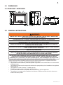
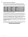
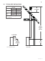
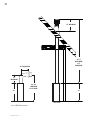
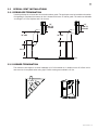
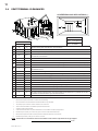
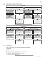
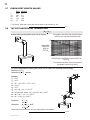

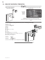
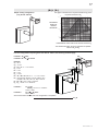
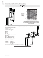
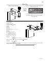
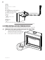
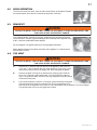
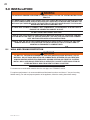
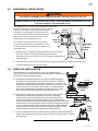
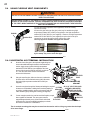
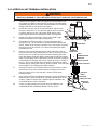
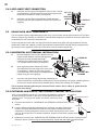

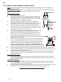

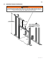
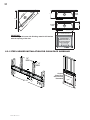
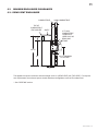
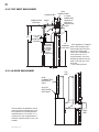
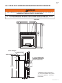
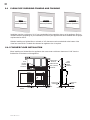
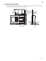
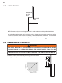
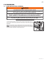
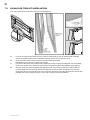
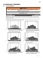
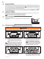
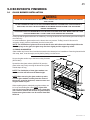
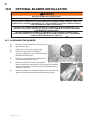
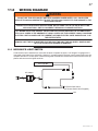

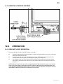
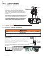
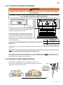

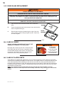
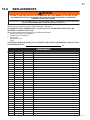
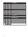
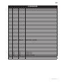

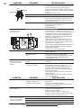
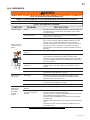
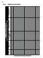

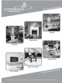
![Foyer Napoléon GD-36 manuel Fr [3,11 Mo]](http://vs1.manualzilla.com/store/data/006313775_2-728e225ad06644f8febf76921e05f7d5-150x150.png)