1
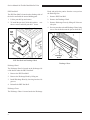
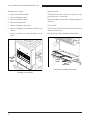
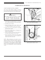
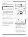
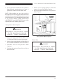
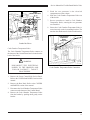
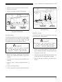
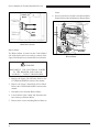
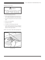
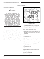
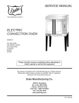
Service Manual FLEXIBLE BATCH BROILER MODELS FBB-NO-120 FBB-NC-120 FBB-PO-120 FBB-PC-120 Please read this manual completely before attempting to install, operate or service this equipment This document is prepared for trained Duke service technicians. It is not to be used by anyone not properly qualified to perform these procedures. This Service Manual is not all encompassing. If you have not been trained on servicing this product, be sure to read the manual completely before attempting servicing. Be sure all necessary tools, test equipment, and skills are available. Those procedures for which you do not have the proper skills and test equipment must be performed only by a qualified Duke trained service technician. This manual is Copyright © 2011 Duke Manufacturing Co. All rights reserved. Reproduction without written permission is prohibited. Duke is a registered trademark of the Duke Manufacturing Co. Duke Manufacturing Co. 2305 N. Broadway St. Louis, MO 63102 Phone: 314-231-1130 Toll Free: 1-800-735-3853 Fax: 314-231-5074 www.dukemfg.com P/N 175782C Service Manual for Flexible Batch Broiler Units IMPORTANT WARNING AND SAFETY INFORMATION IMPORTANT FOR YOUR SAFETY THIS MANUAL HAS BEEN PREPARED FOR PERSONNEL QUALIFIED TO INSTALL GAS EQUIPMENT. THE QUALIFIED INSTALLER SHOULD PERFORM THE INITIAL FIELD STARTUP AND ADJUSTMENTS OF THE EQUIPMENT COVERED BY THIS MANUAL. IMPORTANT THE INSTRUCTIONS TO BE FOLLOWED IN THE EVENT THE SMELL OF GAS IS DETECTED SHOULD BE POSTED IN A PROMINENT LOCATION. THIS INFORMATION CAN BE OBTAINED FROM THE LOCAL GAS SUPPLIER. IMPORTANT IN THE EVENT A GAS ODOR IS DETECTED, SHUT DOWN BROILER AT MAIN SHUTOFF VALVE AND CONTACT THE LOCAL GAS COMPANY OR GAS SUPPLIER FOR SERVICE. IMPORTANT FOR YOUR SAFETY DO NOT STORE OR USE GASOLINE OR OTHER FLAMMABLE VAPORS OR LIQUIDS IN THE VICINITY OF THIS OR ANY OTHER APPLIANCE. WARNING IMPROPER INSTALLATION, ADJUSTMENT, ALTERATION, SERVICE OR MAINTENANCE CAN CAUSE PROPERTY DAMAGE, INJURY OR DEATH. READ THE INSTALLATION, OPERATING AND MAINTENANCE INSTRUCTIONS THOROUGHLY BEFORE INSTALLING OR SERVICING THIS EQUIPMENT. WARNING IN THE EVENT OF A POWER FAILURE, DO NOT ATTEMPT TO OPERATE THIS DEVICE. 2 Service Manual for Flexible Batch Broiler Units TABLE OF CONTENTS INSTALLATION....................................................................................................................5 OPERATION.........................................................................................................................5 CLEANING...........................................................................................................................5 SPECIFICATIONS................................................................................................................6 TOOLS ...............................................................................................................................6 Standard........................................................................................................................6 REMOVAL AND REPLACEMENT OF COMPONENTS.......................................................7 COVERS AND PANELS.......................................................................................................7 Upper Lift Off Panel.......................................................................................................7 Lower Control Side Service Panel.................................................................................7 Discharge Tray..............................................................................................................8 Discharge Hood.............................................................................................................8 Discharge Chute............................................................................................................8 Discharge Pan...............................................................................................................9 Discharge Grease Pan..................................................................................................9 Discharge Access Panel................................................................................................10 Main Grease Pan..........................................................................................................10 Grease V Pan................................................................................................................10 Loader Tray...................................................................................................................11 Conveyor Drive Motor Cover.........................................................................................11 Top Service Panel.........................................................................................................12 Removing the Front Panel.............................................................................................12 Removing the Rear Panel.............................................................................................12 COMPONENT REMOVAL....................................................................................................13 Conveyor Drive Motor Assembly...................................................................................13 Conveyor Drive Chain ..................................................................................................14 Conveyor Drive Motor Sprocket....................................................................................14 Conveyor Drive Motor Capacitor...................................................................................15 Blower Hose..................................................................................................................16 Upper Flame Sensor Assembly.....................................................................................16 Upper Igniter Assembly.................................................................................................17 Lower Flame Sensor Assembly.....................................................................................17 Lower Igniter Assembly.................................................................................................18 Upper Infrared Burner Assembly...................................................................................18 Lower J Burner .............................................................................................................19 Ignition Modules............................................................................................................20 Combo Gas Valves........................................................................................................20 Cook Chamber Temperature Probe..............................................................................21 Control Board................................................................................................................22 Step-Down Transformers..............................................................................................23 3 Service Manual for Flexible Batch Broiler Units TABLE OF CONTENTS (CONTINUED) Solid-State Relays.........................................................................................................23 Main Power Switch......................................................................................................................24 Blower Motor...............................................................................................................................24 Replacing Conveyor Links...........................................................................................................25 ADJUSTMENTS.................................................................................................................................26 Incoming Gas Pressure.................................................................................................................26 Combo Gas Valves.......................................................................................................................26 Drive Chain Deflection................................................................................................................27 Conveyor Position Adjustment....................................................................................................27 Upper Infrared Burner Air Supply...............................................................................................28 Lower Burner Air Supply.............................................................................................................28 TROUBLESHOOTING CHART........................................................................................................29 SCHEMATIC DIAGRAM...................................................................................................................39 REPLACEMENT PARTS LIST..........................................................................................................40 4 Service Manual for Flexible Batch Broiler Units INTRODUCTION INSTALLATION CLEANING For detailed installation instructions, refer to the Installation and Operation Manual. For specific cleaning instructions, refer to the Installation and Operation Manual. OPERATION For specific operating instructions, refer to the Installation and Operation Manual. 5 Service Manual for Flexible Batch Broiler Units SPECIFICATIONS NATURAL GAS PROPANE MANIFOLD PRESS. TOP BURNERS 3.75″ WC 0.93 kPa 8″ WC 2.0 kPa MANIFOLD PRESS. BOT. BURNER 3.75″ WC 0.93 kPa 8″ WC 2.0 kPa ALTITUDE (MAXIMUM) 2000 FT 607 m 2000 FT 607 m GAS PIPE CONNECTION 3/4" F-NPT 3/4" F-NPT INLET PRESSURE RANGE 7"–12" W.C. 10"–12" W.C. TOTAL ENERGY RATE 87,000 – 111,000 BTU/HR 25.5 –32.5 kW 79,000 –105,000 BTU/HR 23.2 –30.7 kW BURNER ORIFICE SIZE BURNER ORIFICE SIZE FRONT INFRARED BURNER #40 2.49mm #52 1.61mm BACK INFRARED BURNER #36 2.70mm #51 1.70mm LOWER BURNER #31 2.05mm #49 1.85mm MODEL NUMBER VOLTAGE AMPS CYCLE PLUG *FBB-NO-120 120 2 60 NEMA 5-15P *FBB-NC-120 120 2 60 NEMA 5-15P *FBB-PO-120 120 2 60 NEMA 5-15P *FBB-PC-120 120 2 60 NEMA 5-15P SHIPPING WEIGHT lbs Kg BATCH BROILER (STANDARD) 482 219 SHIPPING DIMENSIONS Standard Metric (cm) LXWXH 47″ X 34″ X 68″ 119.4 X 86.4 X 172.7 ELECTRICAL * Model Number Information: • FBB-NO-120: Natural Gas No Catalyst • FBB-NC-120: Natural Gas with Catalyst • FBB-PO-120: Propane Gas No Catalyst • FBB-PC-120: Propane Gas with Catalyst TOOLS Standard • Standard set of hand tools. • VOM with AC current tester (Any quality VOM with a sensitivity of at least 20,000 ohms per volt can be used). • Manometer • Pyrometer • Gas Leakage Tester or method to test for gas leaks • Conveyor Link Removal Pliers • Duke Testing Harness 6 WARNING THIS BROILER IS DESIGNED TO OPERATE WITH INCOMING NATURAL GAS PRESSURES BETWEEN 7" AND 12" WATER COLUMN (WC). SERVICE PRESSURES ABOVE 12" WC OR LESS THAN 2 PSI, WILL REQUIRE DUKE’S HIGH SUPPLY NATURAL GAS KIT (P/N 175689). THE KIT INCLUDES COMPONENTS TO ADD AN EXTERNAL REGULATOR TO THE BROILER. THE REGULATOR SHOULD BE ADJUSTED AFTER INSTALLATION TO 7" WC PER THE ENCLOSED INSTRUCTIONS. FOR INCOMING PRESSURE LESS THAN 7" WC CONTACT GAS SUPPLIER. Service Manual for Flexible Batch Broiler Units REMOVAL AND REPLACEMENT OF COMPONENTS COVERS AND PANELS WARNING DISCONNECT THE ELECTRICAL POWER TO THE BROILER AND FOLLOW LOCKOUT / TAGOUT PROCEDURES. Caution: If the broiler has been operating, broiler panels and components may be hot. Use PROPER PROTECTION. Upper Lift Off Panel Lower Control Side Service Panel The Lower Control Side Service Panel provides access to the Combo Gas Valves, Ignition Modules, Transformers, Blower Motor, Conveyor Motor Capacitor, and electrical connections to the Control Board. 1. Remove the six screws securing the Lower Control Side Service Panel. 2. Remove the panel from the broiler. 3. Reverse procedure to install the Lower Control Side Service Panel. Control Side Service Panel The Upper Lift Off Panel provides access to the Upper Flame Sensors, Igniters and Blower Hose. 1. Remove Upper Lift Off Panel by lifting up and removing from broiler. 2. Install Upper Lift Off Panel by lowering into the side grooves. Screws Lower Control Side Service Panel Control Side Access Panel Upper Lift Off Panel 7 Service Manual for Flexible Batch Broiler Units PHU Pan Shelf The PHU Pan Shelf is located on the discharge side of the broiler and holds the unused holding pans. Hood and guides the patties from the conveyor into the Discharge Pan. 1. Remove PHU Pan Shelf. 1. Lift the pan shelf up and remove. 2. Remove the Discharge Hood. 2. To install the pan shelf, slide the keyholes over the two screws and slide pan shelf down. 3. Remove Discharge Chute by lifting off of the two side pins. 4. Reverse procedure to install Discharge Chute, being sure to rest the hooks onto the pins on both sides. PHU Pan Shelf Pin Discharge Hood Discharge Chute Pin Hook PHU Pan Shelf and Discharge Hood Discharge Hood The Discharge Hood is located on the discharge side of the broiler under the PHU Pan Shelf. 1. Remove the PHU Pan Shelf. 2. Remove the Discharge Hood by lifting out. 3. Install Discharge Hood by lowering into the side grooves. 4. Reinstall the PHU Pan Shelf. Discharge Chute The Discharge Chute is located under the Discharge 8 Discharge Chute Service Manual for Flexible Batch Broiler Units Discharge Pan Discharge Grease Pan The Discharge Pan is located on the discharge side of the broiler below the Discharge Hood and is used to support the PHU Holding Pan (not supplied). The Discharge Grease Pan is located below the Discharge Pan and catches any grease drippings. 1. Remove the PHU Holding Pan if present. 2. Slide Discharge Pan up and out of keyhole slots. 3. Install Discharge Pan by lowering it into the thumbscrews. Discharge Pan 1. Tilt Discharge Grease Pan up to unhook and pull forward to remove. 2. When installing the Discharge Grease Pan, be sure to tilt up and push all the way back. NOTE: Correct positioning will not allow pan removal without upward tilt. 1 2 Discharge Pan Discharge Grease Pan Discharge Grease Pan 9 Service Manual for Flexible Batch Broiler Units Discharge Access Panel Main Grease Pan 1. Remove the PHU Pan Shelf. The Main Grease Pan is located on the front of the broiler under the V Grease Pan. 2. Remove Discharge Hood. 3. Remove Discharge Chute. 4. Remove Discharge Pan. Remove the Main Grease Pan by sliding straight out of broiler. 5. Remove Discharge Grease Pan. V Grease Pan 6. Remove Discharge Access Panel by lifting it up and out. The V Grease Pan is located on the front of the broiler under the Loader Tray. 7. Reverse procedure to install Discharge Access Panel. Remove pan by sliding straight out from broiler. Discharge Side Access Panel Grease V-Pan Main Grease Pan V Grease Pan and Main Grease Pan Discharge Access Panel 10 Service Manual for Flexible Batch Broiler Units Loader Tray Conveyor Drive Motor Cover The Loader Tray is located on the front of the broiler and slides into the channels on the Loader Brackets. The Conveyor Drive Motor Cover, located on the lower front of the broiler on the discharge side, covers the Drive Chain Motor. 1. Remove Loader by sliding it out of the Loader Tray. 2. Remove Loader Tray from the Loader Brackets by pulling forward and disengaging ears on Loader Tray from keepers on the Loader Brackets. 3. Install Loader Tray by sliding it into bracket and engaging ears with keepers. 1. Remove the Main Grease Pan and the V Grease Pan. 2. Remove the three screws securing the cover to the broiler. 3. Lift Conveyor Drive Motor Cover off the broiler. Conveyor Drive Motor Cover Loader Carriage Ear Loader Bracket Conveyor Drive Motor Cover Loader Tray 11 Service Manual for Flexible Batch Broiler Units Top Service Panel The perforated Top Service Panel provides access to the two Infrared Burners Front Access Panel 1. Remove the four screws securing the perforated Top Service Panel. 2. Remove the perforated Top Service Panel from the broiler. 3. Reverse procedure to install the perforated Top Service Panel. Flue Restrictor Top Service Panel Front Panel Removing the Rear Panel 1. Lift the Rear Panel up and away from the broiler. 2. Reverse to reinstall the Rear Panel. Rear Access Panel Top Service Panel Removing the Front Panel 1. Slide the Loader out of the Loader Tray. 2. Unlatch the Loader Tray and slide it out of the Loader Tray Mounting Brackets. 3. Pull the Main Grease Pan out of the front of the broiler. 4. Pull the V Grease Pan out of the front of the broiler. 5. Lift the Front Panel up and away from the broiler. 6. Reverse these steps to reinstall these parts. 12 Rear Panel Service Manual for Flexible Batch Broiler Units COMPONENT REMOVAL CONVEYOR DRIVE MOTOR ASSEMBLY The Conveyor Drive Motor Assembly is located in the lower front of the broiler at the discharge end. The motor drives the Conveyor by use of a drive chain. Screws Motor Assembly WARNING DISCONNECT THE ELECTRICAL POWER TO THE BROILER AND FOLLOW LOCKOUT / TAGOUT PROCEDURES. 1. Remove the Conveyor Drive Motor Cover. Refer to the COVERS and PANELS section of the manual. 2. Disconnect wires to motor. Motor Mounting Plate Conveyor Drive Motor Assembly 3. Remove Discharge Access Panel. Refer to the COVERS and PANELS section of the manual. Chain 4. Remove four screws securing motor to mounting plate and remove motor. 5. Raise motor mounting plate to disengage drive chain from motor pulley. 6. Remove sprocket from motor shaft. Sprocket is secured to motor shaft by two set screws. 7. Reverse procedure to install a new motor. Ensure that one of the sprocket set screws is tightened to the flat side of the motor shaft. NOTE: When installing the new motor, be sure to engage the chain on the motor sprocket. Adjust the tension on the chain to allow 3/16″ chain deflection, as described in the procedure DRIVE CHAIN DEFLECTION ADJUSTMENT in the ADJUSTMENT Section, before tightening the motor mounting plate screws. Motor Sprocket Motor Sprocket and Drive Chain 13 Service Manual for Flexible Batch Broiler Units Conveyor Drive Chain The Conveyor Drive Chain connects the drive motor to the Conveyor. Conveyor Sprocket WARNING DISCONNECT THE ELECTRICAL POWER TO THE BROILER AND FOLLOW LOCKOUT / TAGOUT PROCEDURES. Chain Motor Sprocket 1. Remove Conveyor Drive Motor Cover. Refer to the COVERS and PANELS section of the manual. 2. Remove Discharge Access Panel. Refer to the COVERS and PANELS section of the manual. 3. Disconnect motor wires. 4. Remove four screws securing motor mounting plate. 5. Raise motor mounting plate to disengage drive chain from motor sprocket. 6. Disengage chain from conveyor sprocket. 7. Remove chain from broiler by removing the master link. 8. Reverse procedure to install a new chain. NOTE: When installing the new chain, be sure to engage the chain on the motor sprocket and conveyor sprocket. Then adjust the tension on the chain to allow 3/16″ chain deflection, as described in the procedure DRIVE CHAIN DEFLECTION ADJUSTMENT in the ADJUSTMENT Section, before tightening the motor mounting plate screws. Drive Chain and Sprockets Conveyor Drive Motor Sprocket The Conveyor Drive Motor Sprocket is attached to the motor shaft. WARNING DISCONNECT THE ELECTRICAL POWER TO THE BROILER AND FOLLOW LOCKOUT / TAGOUT PROCEDURES. 1. Remove Conveyor Drive Motor Cover. Refer to the COVERS and PANELS section of the manual. 2. Remove Discharge Access Panel. Refer to the COVERS and PANELS section of the manual. 3. Disconnect the motor wires. 4. Remove the four screws securing motor mounting plate. 5. Raise motor mounting plate to disengage drive chain from motor sprocket. 6. Disengage drive chain from motor sprocket. 7. Loosen the two setscrews on motor sprocket and remove sprocket from motor shaft. 14 Service Manual for Flexible Batch Broiler Units 8. Reverse procedure to install a new Conveyor Drive Motor Sprocket, ensuring that one set screw is tightened to the flat side of the motor shaft. NOTE: When installing the new Conveyor Drive Motor Sprocket, be sure to engage the chain on the motor sprocket and conveyor sprocket, then adjust the tension on the chain to allow 3/16″ chain deflection as described in the procedure DRIVE CHAIN DEFLECTION ADJUSTMENT in the ADJUSTMENT Section, before tightening the motor mounting plate screws. 5. Remove screw securing capacitor to frame and remove Conveyor Drive Motor Capacitor. 6. Reverse procedure to install a new Conveyor Drive Motor Capacitor. Conveyor Drive Motor Capacitor Conveyor Drive Motor Capacitor WARNING DISCONNECT THE ELECTRICAL POWER TO THE BROILER AND FOLLOW LOCKOUT / TAGOUT PROCEDURES. Conveyor Drive Motor Capacitor 1. Remove the Upper Lift Off Panel. Refer to the COVERS and PANELS section of the manual. 2. Remove Lower Control Side Service Panel. Refer to the COVERS and PANELS section of the manual. 3. Disconnect wires to Conveyor Drive Motor Capacitor. 4. Discharge the capacitor. Ground the two leads to the broiler frame. Blower Hose WARNING DISCONNECT THE ELECTRICAL POWER TO THE BROILER AND FOLLOW LOCKOUT / TAGOUT PROCEDURES. 15 Service Manual for Flexible Batch Broiler Units 1. Remove Upper Lift Off Panel. Refer to the COVERS and PANELS section of the manual. Mounting Guide 2. Loosen Blower Hose clamp at output of Blower Motor. 3. Loosen hose clamp at center of air supply to upper burners. Porcelain Insulator 4. Remove Blower Hose. 5. Reverse procedure to install Blower Hose. Air Tube Clamp Flame Sensors Infrared Air Tube Flame Sensor Wire Upper Flame Sensor 4. Disconnect Upper Flame Sensor wire from Ignition Module and remove Upper Flame Sensor Assembly. Blower Hose Upper Flame Sensor Assemblies The Upper Flame Sensor Assemblies are accessible by removing the Upper Lift Off Panel. Each upper burner has a corresponding Flame Sensor Assembly. WARNING DISCONNECT THE ELECTRICAL POWER TO THE BROILER AND FOLLOW LOCKOUT / TAGOUT PROCEDURES. 1. Remove the Control Side Access Panel. Refer to the COVERS and PANELS section of the manual. 2. Remove Lower Control Side Service Panel. Refer to the COVERS and PANELS section of the manual. 3. Disengage Upper Flame Sensor from guide and bracket, and pull out of guide and bracket. 5. Pinch the tabs on the wire grommets to remove them. 6. Feed wire through shelf to completely remove the Flame Sensor Assembly. 7. Reverse procedure to install a new Upper Flame Sensor Assembly. Upper Igniter Assemblies The Upper Igniter Assemblies are accessible by removing the Upper Lift Off Panel. Each upper burner has a corresponding Igniter Assembly WARNING DISCONNECT THE ELECTRICAL POWER TO THE BROILER AND FOLLOW LOCKOUT / TAGOUT PROCEDURES. 1. Remove the Upper Lift Off Panel. Refer to the COVERS and PANELS section of the manual. 2. Remove Lower Control Side Service Panel. Refer to the COVERS and PANELS section of the manual. 3. Remove two screws securing igniter cover. 16 Service Manual for Flexible Batch Broiler Units 3. Disengage Lower Flame Sensor from guide and bracket and pull out of guide and bracket. Sensor/Igniter Support Bracket Ground Wires Nut Igniters Bracket Cables Upper Igniters 4. Disconnect the cable and ground wire from the Igniter. 5. Remove Blower Hose. Lower Flame Sensor Lower Flame Sensor 6. Remove the two remaining screws that secure the Air Box Cover and remove the Air Box Cover. 4. Disconnect Lower Flame Sensor wire from Lower Ignition Module, and remove Lower Flame Sensor Assembly. 7. Remove the Sensor/Igniter Support Bracket. 5. Pinch the tabs on the wire grommet to remove it. 8. Remove the nut securing the Igniter. 6. Feed the wire through the hole to fully remove the Flame Sensor Assembly. 9. Reverse procedure to install a new Upper Igniter, ensuring the replacement Igniter has the proper 1/8" spark gap. For proper ignition, the spark should be approximately 3/16" away from the surface of the IR burner tile. Lower Flame Sensor Assembly 7. Reverse procedure to install a new Lower Flame Sensor Assembly. Lower Igniter Assembly The Lower Igniter Assembly is accessible by removing the Upper Lift Off Panel. The Lower Flame Sensor Assembly is accessible from the back of the broiler. WARNING WARNING DISCONNECT THE ELECTRICAL POWER TO THE BROILER AND FOLLOW LOCKOUT / TAGOUT PROCEDURES. DISCONNECT THE ELECTRICAL POWER TO THE BROILER AND FOLLOW LOCKOUT / TAGOUT PROCEDURES. 1. Remove the Upper Lift Off Panel. Refer to the COVERS and PANELS section of the manual. 1. Remove Lower Control Side Service Panel. Refer to the COVERS and PANELS section of the manual. 2. Disconnect Lower Igniter cable and ground wire from the Igniter. 2. Remove Rear Panel. Refer to the COVERS and PANELS section of the manual. 3. Remove the nut securing the Igniter. 17 Service Manual for Flexible Batch Broiler Units 4. Reverse procedure to install a new Lower Igniter Assembly, ensuring the replacement Igniter has the proper 1/8" spark gap. For proper ignition, the spark should be approximately 3/4" above the lower burner. Upper Infrared Burner Assembly There are two Infrared Burners located on the top of the broiler. These Infrared Burners can be accessed by removing the Top Service Panel and Impedance Pan. WARNING DISCONNECT THE ELECTRICAL POWER TO THE BROILER AND FOLLOW LOCKOUT / TAGOUT PROCEDURES. WARNING SHUT OFF THE GAS SUPPLY BEFORE SERVICING THE UNIT. 5. Remove both Igniter Guards. 6. Remove Blower Hose. 7. Remove Air Box Cover. 8. Remove the four screws that secure the Burner Venturi to the Air Box. 9. Use a putty knife to gently pry the Burner Venturi from the Air Box. 10. Lift Infrared Burner Assembly out of top of broiler, by sliding the burner forward, up and out of the broiler. 11. Reverse procedure to install a new Infrared Burner Assembly. NOTE: Use Anti-Seize Technologies TFE1400 pipe thread sealant on all gas line fittings when reassembling the Infrared Burner gas lines. NOTE: Clean excess silicone sealer from Air Box and Burner Venturi if reinstalling burner. Reapply high temp silicone sealer before installing burner. Lower J Burner Assembly WARNING CHECK ALL GAS JOINTS DISTURBED DURING SERVICING FOR LEAKS. CHECK USING A SOAP AND WATER SOLUTION (BUBBLES). DO NOT USE AN OPEN FLAME. Caution: If the broiler has been operating, broiler panels and components may be hot. Use proper protection. 1. Remove Impedance Pan. Refer to the COVERS and PANELS section of the manual. 2. Remove Lower Control Side Service Panel. Refer to the COVERS and PANELS section of the manual. 3. Disconnect gas line at input to top Infrared Burner Assembly to be removed. 4. Remove nuts which run along the length of the burner. 18 The Lower J Burner Assembly is located under the Conveyor and can be accessed at the discharge end of the broiler and from the front of the broiler. WARNING DISCONNECT THE ELECTRICAL POWER TO THE BROILER AND FOLLOW LOCKOUT / TAGOUT PROCEDURES. 1. 2. 3. 4. 5. 6. Remove PHU Pan Shelf. Remove Discharge Hood. Remove Discharge Chute. Remove Discharge Pan. Remove the Discharge Grease Pan Remove the Discharge Access Panel. Refer to the COVERS and PANELS section of the manual. 7. Remove the Ash Scraper, by pulling thetop of the Ash Scrapper out, away from the broiler and lifting it up and out. Service Manual for Flexible Batch Broiler Units 8. Remove the Main Grease Pan and V Grease Pan. 9. Remove Front Panel. Refer to the COVERS and PANELS section of the manual. 10. Disengage J Burner bracket from stud at discharge end, and move J Burner toward discharge end to disengage from its orifice. 11. Carefully slide J Burner Assembly out of front of broiler, taking care not to damage the Igniter Assembly. J Burner Air Shutter Input End Lower J Burner Assembly Gas Connection Ignition Modules Air Box Mounting Plate The Ignition Modules are accessible by removing the Lower Control Side Service Panel. The Ignition Modules are at the bottom of the compartment behind the Relays. WARNING Infrared Burner Assembly 12. Reverse procedure to install a new J Burner Assembly. NOTE: Be sure J Burner input end engages the gas orifice and that the discharge end of the J Burner sits securely in the burner bracket. DISCONNECT THE ELECTRICAL POWER TO THE BROILER AND FOLLOW LOCKOUT / TAGOUT PROCEDURES. 1. Remove the Lower Control Side Service Panel. Refer to the COVERS and PANELS section of the manual. 2. Tag and disconnect the wires to the Ignition Module to be removed. 3. Disconnect the Flame Sensor wire/s. 4. Remove the two screws attaching Ignition Module to frame and remove the module. 5. Reverse this procedure to replace an Ignition Module. 19 Service Manual for Flexible Batch Broiler Units WARNING Flame Sensor Wires ALL JOINTS PRIOR TO THE COMBO GAS VALVE MUST BE CHECKED BEFORE LIGHTING THE UNIT. WARNING Lower Ignition Module Screws Upper Ignition Module Ignition Modules NOTE: Combo Gas Valves are not serviceable and must not be disassembled. 1. Shut off gas to broiler. Combo Gas Valves WARNING DISCONNECT THE ELECTRICAL POWER TO THE BROILER AND FOLLOW LOCKOUT / TAGOUT PROCEDURES. WARNING SHUT OFF THE GAS SUPPLY BEFORE SERVICING THE BROILER. WARNING CHECK ALL GAS JOINTS DISTURBED DURING SERVICING FOR LEAKS. CHECK USING A SOAP AND WATER SOLUTION (BUBBLES). DO NOT USE AN OPEN FLAME. 20 ALL JOINTS BEYOND THE COMBO GAS VALVE MUST BE CHECKED AFTER UNIT IS LIT. 2. Remove the Upper Lift Off Panel and Lower Control Side Service Panel. Refer to the COVERS and PANELS section of the manual. 3. Disconnect gas line going to the burner assembly at the Combo Gas Valve. 4. Tag and disconnect wires to the Combo Gas Valve. 5. Using a pipe wrench unscrew the Combo Gas Valve from the input gas line. 6. Reverse procedure to install a Combo Gas Valve. Make sure the new Combo Gas Valve is installed in the right direction. NOTE: Use Anti-Seize Technologies TFE1400 pipe thread sealant on all gas line fittings when replacing the Combo Gas Valves. 7. Check all gas connections for leaks. 8. Ensure proper gas valve pressure. Service Manual for Flexible Batch Broiler Units Upper Combo Gas Valve Input Gas Lines Burner Gas Lines 5. Pinch the two grommets in the electrical compartment to remove them. 6. Slide the Cook Chamber Temperature Probe out of the broiler. 7. Reverse procedure to install a Cook Chamber Temperature Probe, ensuring the two grommets are reinstalled. 8. Ensure the Cook Chamber Temperature Probe is seated correctly on the its mounting bracket. The notch on the sheath must be locked on the bracket. Lower Combo Gas Valve Cook Chamber Temperature Probe Connection Combo Gas Valves Cook Chamber Temperature Probe The Cook Chamber Temperature Probe connects to the bottom of the Control Board and is located on the back of the broiler. WARNING DISCONNECT THE ELECTRICAL POWER TO THE BROILER AND FOLLOW LOCKOUT / TAGOUT PROCEDURES. Cook Chamber Temperature Probe Connection 1. Remove the Lower Control Side Service Panel. Refer to the COVERS and PANELS section of the manual. 2. Remove the Rear Panel. Refer to the COVERS and PANELS section of the manual. 3. Disconnect the Cook Chamber Temperature Probe connector at the bottom of the Control Board. 4. Remove the Cook Chamber Temperature Probe from the bracket by pushing down gently on the bracket. 21 Service Manual for Flexible Batch Broiler Units 6. Reverse procedure to install a new Control Board. 7. Alert the restaurant manager the Control Board has been replaced and fine adjustments may be required. Screws 9-Pin and 12-Pin Connectors Cook Chamber Temperature Probe Cook Chamber Temperature Probe Mounting Control Board The Control Board is located on the front of the broiler. Control Board programming is preset at the factory with standard BURGER KING® recipes. Any fine adjustments made at the restaurant level are the responsibility of the restaurant manager. WARNING DISCONNECT THE ELECTRICAL POWER TO THE BROILER AND FOLLOW LOCKOUT / TAGOUT PROCEDURES. 1. Remove the Lower Control Side Service Panel. Refer to the COVERS and PANELS section of the manual. 2. Disconnect the Cook Chamber Temperature Probe connector at the bottom of the Control Board. 3. Disconnect the 9-pin and 12-pin connectors from the back of the Control Board. 4. Remove the two screws on the front of the Control Board. 5. Remove Control Board from broiler. Cook Chamber Temperature Probe Control Board Step-Down Transformers Two Step-down Transformers are accessible by removing the Lower Control Side Service Panel. Both Transformers reduce the incoming 120VAC to 24VAC. The left Transformer provides 24VAC to the Control Board. The right Transformer provides 24VAC to operate the Solid-State Relays. WARNING DISCONNECT THE ELECTRICAL POWER TO THE BROILER AND FOLLOW LOCKOUT / TAGOUT PROCEDURES. 1. Remove the Lower Control Side Service Panel. Refer to the COVERS and PANELS section of the manual. 2. Disconnect wires from the Transformer to be removed. 22 Service Manual for Flexible Batch Broiler Units 3. Remove screws securing Transformer to frame. 4. Remove Transformer. 5. Reverse procedure to install a Transformer. Control Board Step-Down Transformer Ignition Module Step-Down Transformer Step-Down Transformers Solid-State Relays Two Solid-State Relays are accessible by removing the Lower Control Side Service Panel. The left Solid-State Relay controls the Conveyor Drive Motor. The right Solid-State Relay controls the Blower Motor. WARNING DISCONNECT THE ELECTRICAL POWER TO THE BROILER AND FOLLOW LOCKOUT / TAGOUT PROCEDURES. 1. Remove the Lower Control Side Service Panel. Refer to the COVERS and PANELS section of the manual. 2. Disconnect wires from the Solid-State Relay to be removed. Conveyor Drive Motor Relay IR Blower Motor Relay Solid-State Relays Main Power Switch The Main Power Switch is located on the front of the broiler below the Control Board. WARNING DISCONNECT THE ELECTRICAL POWER TO THE BROILER AND FOLLOW LOCKOUT / TAGOUT PROCEDURES. 1. Remove Lower Control Side Service Panel. Refer to the COVERS and PANELS section of the manual. 2. Disconnect switch wires. 3. Pinch the spring tabs on the top and bottom of the switch and slide out through front of panel. 4. Reverse procedure to install a new Main Power Switch. 3. Remove screws securing Solid-State Relay to frame. 4. Remove Solid-State Relay. 5. Reverse procedure to install a Solid-State Relay. 23 Service Manual for Flexible Batch Broiler Units frame. 6. Reverse procedure to install a new Blower Motor. Replace gasket when installing new Blower Motor. Control Board Main Power Switch Main Power Switch Hose Clamp Screws Blower Motor The Blower Motor is located on the Control Board side of the broiler and is accessed by removal of the Upper Lift Off and Lower Control Side Service Panels. WARNING DISCONNECT THE ELECTRICAL POWER TO THE BROILER AND FOLLOW LOCKOUT / TAGOUT PROCEDURES. 1. Remove the Upper Lift Off Panel. Refer to the COVERS and PANELS section of the manual. 2. Remove the Lower Control Side Service Panel. Refer to the COVERS and PANELS section of the manual. 3. Disconnect wires from the Blower Motor. 4. Loosen Blower Hose clamp and disconnect the hose from top of Blower Motor. 5. Remove three screws attaching Blower Motor to 24 Blower Motor Assembly Blower Motor Service Manual for Flexible Batch Broiler Units Replacing Conveyor Links WARNING DISCONNECT THE ELECTRICAL POWER TO THE BROILER AND FOLLOW LOCKOUT / TAGOUT PROCEDURES. 1. Turn off and unplug the broiler. 2. Remove the front operator parts and panels. Refer to the COVERS and PANELS section of the manual. 3. Spread the damaged link with Link Tool at both ends. 4. Remove the damaged link. 5. Install the new link. 6. Use pliers to close both ends of the link. 7. Check for proper operation. It may be necessary to add or remove shims behind or under the bushing blocks to ensure proper tension. NOTE: Never remove a link without replacing a link. Spread links Conveyor Links 25 Service Manual for Flexible Batch Broiler Units ADJUSTMENTS INCOMING GAS PRESSURE WARNING THE BROILER IS DESIGNED TO OPERATE WITH INCOMING NATURAL GAS PRESSURES BETWEEN 7" AND 12" WATER COLUMN (WC). SERVICE PRESSURES ABOVE 12" WC AND LESS THAN 2 PSI, WILL REQUIRE DUKE’S HIGH SUPPLY NATURAL GAS KIT (P/N 175689). THE KIT INCLUDES COMPONENTS TO ADD AN EXTERNAL REGULATOR TO THE BROILER. THE REGULATOR SHOULD BE ADJUSTED AFTER INSTALLATION TO 7" WC PER THE ENCLOSED INSTRUCTIONS. COMBO GAS VALVE The two Combo Gas Valves are located next to each other and are accessible by removing the Lower Control Side Service Panel. One gas valve is for the Lower J Burner and the other gas valve is for the Upper Infrared Burners. The gas pressure has been preset at the factory for the type of gas specified on the rating plate; however, it is sometimes necessary to adjust the gas pressure after the unit has been installed. Always check the incoming gas pressure at the tap provided on the inlet pipe before making any valve pressure adjustments. Valve adjustments must be made when both valves are fully open with all burners operating. Upper Combo Gas Valve Input Gas Lines Burner Gas Lines Lower Combo Gas Valve Combo Gas Valve 1. Turn the incoming gas supply to the broiler off. 2. Remove the Upper Lift Off Panel. Refer to the COVERS and PANELS section of the manual. NOTE: Do not disconnect any wiring. 3. Remove the pressure tap plug and replace with the fitting for a gas pressure meter, Slack Tube or Manometer. 4. Attach the meter. 5. Turn gas supply on. NOTE: The pressure regulator is an integral part of the Combo Gas Valve. 6. Locate the adjustment screw by removing the slotted aluminum cap. 7. Adjust pressure reading to 3.75" WC for natural gas or 8.0" WC for Propane Gas. 8. Turn gas supply off. 9. Disconnect meter. 10. Remove fitting and reinstall pressure tap plug. 11. Turn gas supply back on. 12. Check for any gas leaks. 13. Check broiler operation. 26 Service Manual for Flexible Batch Broiler Units DRIVE CHAIN DEFLECTION ADJUSTMENT CONVEYOR POSITION ADJUSTMENT The Drive Chain connects the drive motor to the Conveyor. The Conveyor position is adjusted by adding shims between the Conveyor Shaft Bearing and the frame. 1. Check that the deflection in the Drive Chain does not exceed 3/16″ inch maximum. If the chain requires adjustment, proceed to step 2. 1. Remove Discharge Hood to provide visual access to the Conveyor. 2. Remove Discharge Access Panel. Refer to the COVERS and PANELS section of the manual. 2. Adjust Conveyor height as described in the following illustration. 3. Remove Conveyor Drive Motor Cover. 3. Remove the two screws securing the bearing to the frame. 4. Loosen the four screws securing the motor mount to the frame. 4. Insert shims as necessary between the bearing assembly and the frame. 5. Move the motor mount up or down as necessary to provide 3/16″ deflection at center of chain. 5. Check Conveyor position. 6. Secure the motor mount in place by tightening the four motor mount screws. NOTE: Leading edge of Discharge Chute should be about an 1/8″ above the center line of the Conveyor shaft. When correctly adjusted, the Conveyor link should just graze the backside of the chute. If adjusted too high, the link will roll over the top of the leading edge of the Discharge Chute causing a Conveyor jam. 7. Install Conveyor Drive Motor Cover. 8. Install Discharge Access Panel. INSIDE VIEW Motor Mount 6. If additional shims are required, repeat step 4. NOTE: Additional shims are located inside the Drive Motor Cover. 7. Run Conveyor for several full revolutions to confirm that no jamming occurs. Discharge Chute Position 1/8" above center line of conveyor shaft. Conveyor Shaft Screws Drive Chain Deflection Conveyor Discharge Shaft Adjustment 27 Service Manual for Flexible Batch Broiler Units UPPER IR BURNER AIR SUPPLY The adjustments for the Upper IR Burner air supply are accessible by removing the Upper Lift Off Panel. There are two air adjustment screws located on each side of the blower hose. Air Adjustment Screws NOTE: The air adjustment is factory set and must not be changed unless authorized to do so by Duke Manufacturing. 1. Remove the Upper Lift Off Panel. 2. If found loose, reset to exposed thread measurement to the setting indicated on the broiler. IR Burner Air Adjustment Screws LOWER BURNER AIR SUPPLY The adjustment for the lower burner air supply is factory set and must not be changed. A properly adjusted natural gas burner has a blue flame around the burner bend with no yellow tips on the flame. A propane gas burner may have a small amount of yellow tips on the flames. The Air Shutter opening on factory J Burners is preset and welded to 3/8" open. If replacing the J Burner, verify this opening before installing it. 28 Service Manual for Flexible Batch Broiler Units TROUBLESHOOTING The following troubleshooting information includes checking procedures for various electrical components in order to help identify faulty components. The troubleshooting guide below is designed to identify various symptoms and provide the suggested remedy. COMPONENT CHECK PROCEDURES Checking the Power Switch The Power Switch has a built-in LED that lights red when the switch is in the on position. Check the following before replacing the switch. • Make sure the power cord is plugged into the correct receptacle. The broiler operates on 120VAC 60Hz line current. on. Observe the display and product key LEDs. 5. Turn the power off and reattach the Control Board if the problem is solved. Checking the Conveyor Drive Motor The Conveyor Drive Motor is located on the front of the broiler on the lower discharge side. Before replacing it, check the Conveyor for jammed meat product. Next, try turning the Conveyor discharge shaft with the Multipurpose Broiler Tool. If the Conveyor does not turn, check the following items: • Check the Discharge Chute. • Check the Loader Ramp. • Check the Ash Scraper. • Check the circuit breaker assigned to the broiler. • Check the Cook Chain (Conveyor). • Try a different receptacle before replacing the switch. • Check the Flame Arrestor. • It’s possible for the LED in the switch to fail. Turn the switch on and check the Control Board display. If the display is active, the LED is burned out, replace the switch. Testing the Conveyor Drive Motor Checking the Control Board Under normal conditions, the Control Board displays the current status of the broiler. It can be used as a diagnostic tool, when it is working properly. Try the following before replacing the Control Board. • Cycle the broiler off and on; observe the Control Board. • Try running the Control Board through a couple of different cook cycles. NOTE: If the Control Board is still not performing properly, try these procedures: The Conveyor Drive Motor may be tested without removing it from the broiler. WARNING DISCONNECT THE ELECTRICAL POWER TO THE BROILER AND FOLLOW LOCKOUT / TAGOUT PROCEDURES. 1. Turn off and disconnect the broiler. 2. Remove the Conveyor Drive Motor Cover. 3. Tag and disconnect the wires. 4. Use an Ohmmeter to measure resistance. 5. Attempt to run the Drive Motor when its disengaged from the Drive Chain. 1. Turn the broiler off. 2. Remove the Control Board. 3. Check each connection on the back of the Control Board. Make sure they are all connected correctly. 4. Loosely attach the Control Board, turn the broiler 29 Service Manual for Flexible Batch Broiler Units NORMAL MOTOR RESISTANCE (120V, 60 HZ) Wires to Test Resistance Black and Brown 24.2 Ω Black and Orange 24.2 Ω Brown and Orange3 49.2 Ω CHECKING CONVEYOR DRIVE MOTOR CAPACITOR If the motor tests OK, check the Capacitor. The Capacitor is located in the service area on the control side of the broiler. WARNING DISCONNECT THE ELECTRICAL POWER TO THE BROILER AND FOLLOW LOCKOUT / TAGOUT PROCEDURES. 1. Remove the Lower Control Side Service Panel. Refer to the COVERS and PANELS section of the manual. 2. Disconnect the wires connected to the Capacitor. 3. Discharge the Capacitor by shorting both terminals to ground at the same time. 4. Use an Ohmmeter to test the Capacitor. NOTE: If both the Drive Motor and Capacitor test OK, the problem is probably with the Drive Motor Relay. CHECKING AND TESTING THE BLOWER MOTOR The Blower Motor provides air to the Upper Infrared Burners. These burners will not function properly if the Blower Motor is not supplying a sufficient amount of air to them. The first thing to check is the Blower Wheel for grease and debris build up. Also, inspect for a loose or damaged Blower Hose. 30 WARNING DISCONNECT THE ELECTRICAL POWER TO THE BROILER AND FOLLOW LOCKOUT / TAGOUT PROCEDURES. 1. Make sure the broiler is off and unplugged. 2. Remove the Lower Control Side Service Panel. Refer to the COVERS and PANELS section of the manual. 3. Remove the Blower Motor Assembly. 4. Check and clean the Blower Wheel as needed. 5. Check that the wheel turns freely. 6. Measure the resistance of the Blower Motor winding. The normal resistance across the Blower Motor winding should be 22.2Ω ± 2.2Ω. NOTE: If the resistance is low, the winding may be shorted. If the resistance is high the winding is open. If the Blower Motor tests OK, the problem is probably with the Blower Motor Relay. TESTING THE RELAYS There are two 24VDC Solid-State Relays in the broiler. One controls the Blower Motor, while the other controls the Conveyor Drive Motor. 1. Remove the Lower Control Side Service Panel. Refer to the COVERS and PANELS section of the manual. 2. Turn on the Main Power Switch. 3. The Blower Motor only runs when there is a call for ignition of the upper Infrared Burners. The Conveyor Drive Motor only runs for 6 seconds at the end of a cook cycle. To test the relay, check for 24VDC on the input of the relay. At the same time, monitor AC current to either the Blower Motor or the Conveyor Drive Motor. When no relay input voltage is present, there will be no amperage draw on the output of the relay. 4. Using an Ohmmeter, check for continuity across output terminals. If Ohmmeter indicates continuity, Relay is OK. If Ohmmeter indicates no continuity, Relay is faulty. Service Manual for Flexible Batch Broiler Units Testing the Transformers There are two 24-volt Step-Down Transformers in the broiler. One supplies power to the Control Board, the other provides power to the Ignition Modules. Either a voltage or a resistance check can be used to test the Transformers. Voltage Test 1. Make sure the broiler is turned off. 2. Remove the Lower Control Side Service Panel. Refer to the COVERS and PANELS section of the manual. 3. Disconnect the secondary winding. 4. Turn the broiler on. 5. Using a VOM, test the voltage output across the secondary winding. Voltage should be 24VAC. Resistance Check WARNING • 24VAC is applied across terminal V1 opening the Lower Combo Gas Valve. • High voltage spark is generated at terminal HV. • When the Flame Sensor detects a current flow of not less than 0.7uA, the Igniter stops sparking. The Lower Ignition Module performs a selfdiagnostic check. It is equipped with an LED that has three states, indicating the type of diagnostic failure: 1. Steady On: Indicates internal failure of the module. The module must be replaced. 2. Two Flashes of the LED: Indicates the burner is lit but no call for heat exists. 3. Three Flashes of the LED: Indicates ignition lockout has occurred. Upper Ignition Module The Upper Ignition Module works in the same manner as the Lower Ignition Module, but it has two Igniters and Flame Sensors. The Control Board will send 24VAC to terminals W and GND on the Upper Ignition Module. • 24VAC is applied to terminal W and Ground, which opens the Upper Combo Gas Valve. • High voltage spark is generated at terminals HV1 and HV2. 1. Turn the broiler off. • 2. Remove the Lower Control Side Service Panel. Refer to the COVERS and PANELS section of the manual. When the Flame Sensors detect a current flow of not less than 0.7uA, the Igniters stop sparking. The Upper Ignition Module performs a self-diagnostic. DISCONNECT THE ELECTRICAL POWER TO THE BROILER AND FOLLOW LOCKOUT / TAGOUT PROCEDURES. 3. Tag and disconnect the wires of the Transformer to be tested. Upper Ignition Module Diagnostic Indicators: 1. Steady On: Indicates an internal control failure. 4. Measure the resistance across the primary. Primary Resistance = 21.8Ω ±10%. 2. Two Flashes: Indicates the burner is lit but no call for heat exists. 5. Measure resistance across secondary. 6. Secondary Resistance = 0.8Ω ±10%. 3. Three Flashes: Indicates ignition lockout has occurred. Lower Ignition Module Testing Checking the Flame Sensors When the Cook Chamber Temperature Probe calls for heat, the Control Board will send 24VAC to terminals TH and GND on the Lower Ignition Module. The Lower Ignition Module first performs a diagnostic check. After the diagnostic, the Lower Ignition Module is activated. Typically, an Ignition Module Lockout is caused by dirty Flame Sensors. Here are some Flame Sensor tips: 31 Service Manual for Flexible Batch Broiler Units • If one Flame Sensor is dirty, clean them all. Allow the Flame Sensor to cool and clean it with an alcohol pad. • Replace a Flame Sensor with damaged porcelain. • Check for debris between the Flame Sensor tip and burner. • Adjust the Flame Sensor if the tip is touching ground. • 32 Make sure all of the Flame Sensor connections are tight. Checking the Igniters Another item to check, if the broiler is not lighting properly, is the Igniters. It is possible for these to get bumped during routine cleaning, causing the gap between the electrodes to change. • The spark gap should be 1/8″. • Replace Igniter if the electrodes are damaged. • Check all connections on the Ignition Module and Igniter. • If gas and spark are present but burner does not light, verify proper location of the upper igniter with regard to burner. The igniters on the the top IR burners should be approximately 3/16" away from the surface of the IR burner tile. The lower igniter should be approximately 3/4″ from the lower burner. Service Manual for Flexible Batch Broiler Units Quick Index Define the Problem... 1 2 3 4 5 6 Display flashing “gAS” and…. bot toP SEnb SEnt STEP 2 STEP 3 STEP 2 STEP 3 Display flashing “tESt” and “Prod” STEP 2-3 and 6 Display showing “Hi” STEP 2 Display showing “Lo” STEP 2 Display showing “Prob” Faulty Probe. Test and replace probe. Conveyor jammed / running all the time STEP 7 33 Service Manual for Flexible Batch Broiler Units TURN BROILER ON Does Controller Display light up? NO Verify 120 VAC present at receptacle. Ensure 120 VAC at incoming terminal block. Faulty switch. Ensure 120 VAC across input / output of on / off switch. Faulty transformer. Ensure 24 VAC across transformer secondary winding. YES Check for broken or improper wire connection. Upon turning on, does the lower burner ignite and stay on? NO Is there spark present on lower igniter? NO Spark gap insufficient or faulty igniter. Ensure lower igniter has sufficient spark gap, spark is sufficiently close to the burner, and spark is not arcing elsewhere. No Gas. Ensure incoming gas supply is available. Faulty Controller. Ensure Controller signals for heat to the lower ignition module. YES Is there spark present at lower burner, but no ignition? NO YES Consult next page YES Faulty ignition cable. Ensure continuity through ignition cable. Dirty burner. Ensure lower burner porting below igniter is free of debris or clogging. Flame should crossover the length of the burner. Faulty ignition module. Ensure lower ignition module signals to open lower gas valve. Faulty gas valve. Ensure gas valve solenoid energizes and gas is present at the lower burner. Dirty orifice. Ensure lower burner orifice is free of debris. 34 YES Is there spark and ignition present, but burner does not stay lit? NO Dirty burner. Ensure lower burner is lighting the whole length of the burner. Dirty Flame sensor. Clean the lower flame sensor. Grounding Flame Sensor. Ensure Sensor rod is not coming in contact with any metal surface or ceramic tile of burner. Wire connection. Ensure flame sensor wire connections are tight. Service Manual for Flexible Batch Broiler Units YES Upon reaching 500 F, do the upper infrared burners ignite and stay lit? YES Consult next page NO Is there spark present at both the upper igniters? YES Is there spark present at both the upper igniters, but no ignition? Is there spark and ignition on both upper burners, but burner(s) do not stay lit? NO NO NO Faulty igniter or insufficient spark gap. Ensure upper igniters have sufficient spark gaps and spark is not arcing elswehere. No Gas. Ensure incoming gas supply is available. Dirty Flame Sensor. Clean the affected upper flame sensor. Faulty Controller. Ensure Controller signals for heat to the upper ignition module. Faulty ignition cable. Ensure continuity through affected ignition cable. Faulty ignition module. Ensure upper ignition module signals to open lower gas valve. Faulty gas valve. Ensure gas valve solenoid energizes and gas is present at the upper burners. Dirty orifice. Ensure upper burner orifices are free of debris. YES YES Grounding Flame Sensor. Ensure Sensor rod is not coming in contact with any metal surface or ceramic tile of burner. Determine flame sensor failure. Check microamp reading from upper ignition module from each sensor while burners are on. If flame sense failure occurring, the affected sensor should fall below 0.7 microcamps. Wire connection. Ensure flame sense wire connections are tight. Faulty Controller. Ensure Controller signals blower motor relay to close. Faulty blower motor or relay. Ensure blower motor energizes and there is sufficient air traveling to the upper burners. Heavy accumulation of grease on the blower wheel can have adverse effects. 35 Service Manual for Flexible Batch Broiler Units YES Does the Broiler reach setpoint temperature and display RDY? NO Display flashing “gAS” and…. NO Display flashing “tESt Prod” NO Display flashing “Hi” or “Lo” NO Display flashing “Prob” YES YES YES See Steps 2-3 and 6 See Step 2 Faulty Probe. Test and replace probe. YES Consult next page YES SEE STEPS 2-3 gAS bot = Failure of bottom sensor to sense flame during Preheat mode gAS toP = Failure of a top sensor to sense flame during Preheat mode gAS Senb = Failure of bottom sensor to sense flame during rdY mode gAS Sent = Failure of a top sensor to sense flame during rdY mode YES 36 Service Manual for Flexible Batch Broiler Units YES Does the Lower Burner cycle on and off to maintain idle temperature? (Typically 680 F) NO See Step 2 YES During a cook cycle, do the upper burners cycle on and off according to the programmed cook cycle? NO No spark present at an upper burner. NO Spark and ignition present on both burners, but burner(s) does not stay lit. NO Cycling of upper burners does not follow programmed cook cycle. YES YES YES YES Faulty igniter or insufficient spark gap. Ensure upper igniters have sufficient spark gaps and spark is not arcing elswehere. No Gas. Ensure incoming gas supply is available. Dirty flame sensor. If sparking continues, regardless if ignition is present, clean the lower flame sensor. Faulty Controller. Ensure Controller signals for heat to the upper ignition module at the appropriate periods during the cook cycle. YES Faulty Controller. Ensure Controller signals for heat to the upper ignition module. Consult next page NO Spark present at both burners, but no ignition. Faulty ignition cable. Ensure continuity through affected ignition cable. Faulty ignition module. Ensure upper ignition module signals to open lower gas valve. Faulty gas valve. Ensure gas valve solenoid energizes and gas is present at the upper burners. Dirty orifice. Ensure upper burner orifices are clear of debris. Faulty Controller. Ensure Controller signals blower motor relay to close. Faulty blower motor or relay. Ensure blower motor energizes and there is sufficient air traveling to the upper burners. Heavy accumulation of grease on the blower wheel can have adverse effects. Faulty ignition module. Ensure upper ignition module is signaling to spark and open the upper gas valve at the appropriate periods during a cook cycle. YES 37 Service Manual for Flexible Batch Broiler Units YES At the end of a cook cycle, does the conveyor belt discharge properly? NO Improperly installed. Discharge chute is not properly in place. Belt hanging up. Conveyor belt is catching on another item, i.e. ash scraper, loader ramp, flame arrestor. YES Loose drive chain. Deflection of chain should be approximately 3/16". Broiler Working Properly Loose motor sprocket. When tightening, ensure motor sprocket is orientated the same way as the shaft sprocket. Faulty Controller. Ensure Controller is signaling to energize the conveyor motor relay. Faulty relay. Ensure conveyor motor relay is closing. Replace relay if conveyor motor running nonstop. Faulty conveyor motor. Test conveyor motor for fault. Faulty capacitor. Test conveyor motor capacitor for fault. 38 Service Manual for Flexible Batch Broiler Units 39 Service Manual for Flexible Batch Broiler Units REPLACEMENT PARTS LIST DESCRIPTION Switch, Main Power Burner, Infrared Burner, Tube, J Style (Natural Gas Only) Burner, Tube, J Style (LP Gas Only) Motor, Conveyor Sprocket, B21X3/8 Bore (Motor) Shaft, Discharge Side Shaft, Right Side Capacitor, Motor-Conveyor Ignition Module, Lower Burner Ignition Module, Upper Burners Transformer, 40VA, 120VAC-24VAC Probe, Temperature C-Chamber Light, Cook Relay, Solid State Chain, Drive Controller Gasket, Control Bezel Gasket, Blower Inlet Blower, Dayton 60HZ, 115VAC Hose, Blower Orifice, Holder IR Valve, Nat-Gas Combo 120VAC (Natural Gas Only) Valve, LP-Gas Combo 120VAC (LP Gas Only) Orifice, Lower Burner, #31 (Natural Gas Only) Orifice, Lower Burner, #49 (LP Gas Only) Orifice, IR, Front, #40 (Natural Gas Only) Orifice, IR, Front, #52 (LP Gas Only) Orifice, IR, Rear, #36 (Natural Gas Only) Orifice, IR, Rear, #51 (LP Gas Only) Orifice Holder 3/8 Comp. Straight X Bulkhead Tubing-Tee to IR, Kit Tubing-Tee to Valve, Kit Tubing, Lower Burner to Valve, Kit 40 PART NUMBER 175503 175780 175934 175934 175867 175517 175037 175038 175507 175868 175869 175516 175977 175550 175870 175551 175873 175510 175511 175871 175189 175542 175531 175766 175823 175737 175735 175767 175736 175768 175545 175476 175477 175178 QTY 1 2 1 1 1 1 1 1 1 1 1 2 1 1 2 1 1 1 1 1 1 2 2 2 1 1 1 1 1 1 1 2 1 1 Service Manual for Flexible Batch Broiler Units REPLACEMENT PARTS LIST, CONTINUED DESCRIPTION Sensor, Lower Burner Sensor, IR Burner Igniter Ignition Suppression Cable, IR Ignition Suppression Cable, Lower Burner Cook, Chain Bushing Block, Conveyor Loader Tray Loader Mounting Bracket Loader Loader Ramp Door Flame Arrestor Burner Shield Discharge Chute PART NUMBER 175534 175535 175536 175537 175538 175674 175525 175430 175878 175444 175741 175429 175293 175200 175340 QTY 1 2 3 2 1 1 4 1 1 1 1 1 1 1 1 Discharge Hood 175778 1 PHU Pan Shelf 175353 1 Discharge Pan 175358 1 Main Grease Pan 175329 1 “V” Grease Pan 175325 1 Side, Grease Pan 175357 1 Pivot Pivot Ash Scraper 175150 1 Rear Panel 175305 1 Front Panel 175300 1 Front, Upper, Lift Off 175392 1 Panel, Access Electrical LWB 175383 1 Panel, Access Discharge 175866 1 Impedance Pan (No Optional Catalyst) 175226 1 Catalyst (Optional) 175480 1 Catalyst Guard 175482 1 Tube Burner Cleaning Tool 175485 1 Flame Rod Tube Cleaner 175701 1 Brush, Flame Rod Tube Cleaner 175705 1 Kit, LP Gas Conversion Kit 175612 Sanitation Pail, Red 175842 1 1 41 Service Manual for Flexible Batch Broiler Units NOTES: 42 Service Manual for Flexible Batch Broiler Units CUSTOMER ASSISTANCE To aid in reporting this unit in case of loss or theft, please record below the model number and serial number located on the unit. We also suggest you record all the information listed and retain for future reference. MODEL NUMBER____________________________ SERIAL NUMBER____________________________ DATE OF PURCHASE_____________________________________________________________________ DEALER____________________________________ TELEPHONE________________________________ SERVICER_ _________________________________ TELEPHONE________________________________ NORTH AMERICA & LATIN AMERICA UK & IRELAND Duke Manufacturing Company 2305 N. Broadway St. Louis, MO 63102 Phone: 314-231-1130 Toll Free: 1-800-735-3853 Fax: 314-231-5074 Duke Mfg UK Duke House Unit 10, Greendale Business Park Woodbury Salterton Exeter Devon - UK EX5 1EW Tel: 01395 234140 FAX: 01395 234154 CONTINENTAL EUROPE ASIA EU Headquarter Office Duke Manufacturing CR s.r.o. Vitavska 219, Stechovice 25207 Phone: +420 257-741-033 Fax: +420 257 741 039 Asia Office Duke Food Service Equipment (shanghai) Company Limited 1F, Building #17-2, 658 Nong Jin Zhong Road Shanghai, China 200335 Tel: +86 21 6876 9272 Fax: +86 21 33600628 TO ACCESS INTERNET: www.dukemfg.com Please provide the following information when you write or call: model number, serial number, date of purchase, your complete mailing address (including zip code), and description of the problem. 43 Service Manual for Flexible Batch Broiler Units Duke Manufacturing Co. 2305 N. Broadway St. Louis, MO 63102 Phone: 314-231-1130 Toll Free: 1-800-735-3853 Fax: 314-231-5074 www.dukemfg.com EU Headquarter Office Duke Manufacturing CR s.r.o. Vitavska 219, Stechovice 25207 Phone: +420 257 741 033 Fax: +420 257 741 039 Duke Mfg UK Duke House Unit 10, Greendale Business Park Woodbury Salterton Exeter Devon - UK EX5 1EW Tel: +44 (0) 1395 234140 FAX: +44 (0) 1395 234154 Asia Office Duke Food Service Equipment (shanghai) Company Limited 1F, Building #17-2, 658 Nong Jin Zhong Road Shanghai, China 200335 Tel: +86 21 6876 9272 Fax: +86 21 33600628 44