1
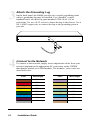
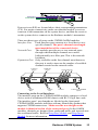
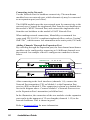
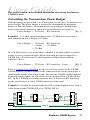
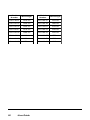
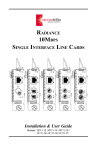
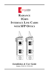
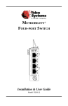
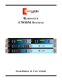
RADIANCE
CWDM SYSTEM
Installation & User Guide
Radiance Coarse Wavelength Division Multiplexing
(CWDM) System
Chassis:
R4000-02 _____ 2-slot 1U rack-mount chassis for CWDM/OADM modules
CWDM Multiplexer/Demultiplexer Modules:
R416-A4-A ____ 4-channel CWDM mux/demux module w/expansion,
1550, 1570, 1590, 1610 nm
R416-A4-B ____ 4-channel CWDM mux/demux module w/expansion,
1470, 1490, 1510, 1530 nm
R416-A4-C ____ 4-channel CWDM mux/demux module w/expansion,
1390, 1410, 1430, 1450 nm
R416-A4-D ____ 4-channel CWDM mux/demux module w/expansion,
1310, 1330, 1350, 1370 nm
R416-B4 ______ 8-channel CWDM mux/demux module,
1470, 1490, 1510, 1530, 1550, 1570, 1590, 1610 nm
R416-A4-AE ___ 4-channel CWDM mux/demux module w/expansion;
1550, 1570, 1590, 1610 nm; extended temperature range
R416-A4-BE ___ 4-channel CWDM mux/demux module w/expansion;
1470, 1490, 1510, 1530 nm; extended temperature range
R416-A4-CE ___ 4-channel CWDM mux/demux module w/expansion;
1390, 1410, 1430, 1450 nm; extended temperature range
R416-A4-DE ___ 4-channel CWDM mux/demux module w/expansion;
1310, 1330, 1350, 1370 nm; extended temperature range
Optical Add/Drop Multiplexing (OADM) Drop/Pass Modules:
R426-D4-31 ____ 1-channel OADM drop/pass module, 1310 nm
R426-D4-33 ____ 1-channel OADM drop/pass module, 1330 nm
R426-D4-35 ____ 1-channel OADM drop/pass module, 1350 nm
R426-D4-37 ____ 1-channel OADM drop/pass module, 1370 nm
R426-D4-39 ____ 1-channel OADM drop/pass module, 1390 nm
R426-D4-41 ____ 1-channel OADM drop/pass module, 1410 nm
R426-D4-43 ____ 1-channel OADM drop/pass module, 1430 nm
R426-D4-45 ____ 1-channel OADM drop/pass module, 1450 nm
R426-D4-47 ____ 1-channel OADM drop/pass module, 1470 nm
R426-D4-49 ____ 1-channel OADM drop/pass module, 1490 nm
R426-D4-51 ____ 1-channel OADM drop/pass module, 1510 nm
R426-D4-53 ____ 1-channel OADM drop/pass module, 1530 nm
R426-D4-55 ____ 1-channel OADM drop/pass module, 1550 nm
R426-D4-57 ____ 1-channel OADM drop/pass module, 1570 nm
R426-D4-59 ____ 1-channel OADM drop/pass module, 1590 nm
R426-D4-61 ____ 1-channel OADM drop/pass module, 1610 nm
© 2003-2004 Metrobility Optical Systems, Inc.
All rights reserved.
Printed in USA.
This publication is protected by the copyright laws of the United States and other countries, with all rights reserved. No
part of this publication may be reproduced, stored in a retrieval system, translated, transcribed, or transmitted, in any
form, or by any means manual, electric, electronic, electromagnetic, mechanical, chemical, optical or otherwise, without
prior explicit written permission of Metrobility Optical Systems, Inc.
OADM Drop/Pass Modules (continued):
R426-D4-47E __ 1-channel OADM drop/pass module, 1470 nm, extended temp
R426-D4-49E __ 1-channel OADM drop/pass module, 1490 nm, extended temp
R426-D4-51E __ 1-channel OADM drop/pass module, 1510 nm, extended temp
R426-D4-53E __ 1-channel OADM drop/pass module, 1530 nm, extended temp
R426-D4-55E __ 1-channel OADM drop/pass module, 1550 nm, extended temp
R426-D4-57E __ 1-channel OADM drop/pass module, 1570 nm, extended temp
R426-D4-59E __ 1-channel OADM drop/pass module, 1590 nm, extended temp
R426-D4-61E __ 1-channel OADM drop/pass module, 1610 nm, extended temp
OADM Drop/Insert Modules:
R436-J4-31 ____ 1-channel OADM drop/insert module, 1310 nm
R436-J4-33 ____ 1-channel OADM drop/insert module, 1330 nm
R436-J4-35 ____ 1-channel OADM drop/insert module, 1350 nm
R436-J4-37 ____ 1-channel OADM drop/insert module, 1370 nm
R436-J4-39 ____ 1-channel OADM drop/insert module, 1390 nm
R436-J4-41 ____ 1-channel OADM drop/insert module, 1410 nm
R436-J4-43 ____ 1-channel OADM drop/insert module, 1430 nm
R436-J4-45 ____ 1-channel OADM drop/insert module, 1450 nm
R436-J4-47 ____ 1-channel OADM drop/insert module, 1470 nm
R436-J4-49 ____ 1-channel OADM drop/insert module, 1490 nm
R436-J4-51 ____ 1-channel OADM drop/insert module, 1510 nm
R436-J4-53 ____ 1-channel OADM drop/insert module, 1530 nm
R436-J4-55 ____ 1-channel OADM drop/insert module, 1550 nm
R436-J4-57 ____ 1-channel OADM drop/insert module, 1570 nm
R436-J4-59 ____ 1-channel OADM drop/insert module, 1590 nm
R436-J4-61 ____ 1-channel OADM drop/insert module, 1610 nm
R436-J4-47E ___ 1-channel OADM drop/insert module, 1470 nm, extended temp
R436-J4-49E ___ 1-channel OADM drop/insert module, 1490 nm, extended temp
R436-J4-51E ___ 1-channel OADM drop/insert module, 1510 nm, extended temp
R436-J4-53E ___ 1-channel OADM drop/insert module, 1530 nm, extended temp
R436-J4-55E ___ 1-channel OADM drop/insert module, 1550 nm, extended temp
R436-J4-57E ___ 1-channel OADM drop/insert module, 1570 nm, extended temp
R436-J4-59E ___ 1-channel OADM drop/insert module, 1590 nm, extended temp
R436-J4-61E ___ 1-channel OADM drop/insert module, 1610 nm, extended temp
Accessories:
R1000-RM _____ 21-inch rackmounting hardware
4000-CA ______ four 1-meter LC-to-SC singlemode fiber cables
Metrobility, Metrobility Optical Systems, and NetBeacon are registered trademarks of Metrobility Optical Systems, Inc. The
Metrobility Optical Systems logo is a trademark of Metrobility Optical Systems, Inc. All other trademarks are the property
of their respective owners.
The information contained in this document is assumed to be correct and current. The manufacturer is not responsible for
errors or omissions and reserves the right to change specifications at any time without notice.
Table of Contents
Radiance CWDM System Installation & User Guide
Table of Contents ................................................................................................. 4
Overview ............................................................................................................... 5
Product Features ............................................................................................ 6
System Description .............................................................................................. 7
CWDM Components ..................................................................................... 7
Mux/Demux ........................................................................................... 8
Expansion Port ................................................................................ 8
Drop/Pass Module ................................................................................ 10
Drop/Insert Module .............................................................................. 11
Installation Guide .............................................................................................. 12
Unpack the System ...................................................................................... 12
Mount the Chassis ....................................................................................... 13
Attach the Grounding Lug ........................................................................... 14
Connect to the Network ............................................................................... 14
User Guide ......................................................................................................... 17
Calculating the Transmission Power Budget .............................................. 17
Calculating the Maximum Link Distance ............................................ 19
Software Support ......................................................................................... 20
Topology Solutions ..................................................................................... 21
Replacing a Module .................................................................................... 24
Technical Specifications .............................................................................. 25
Abbreviations .............................................................................................. 27
Product Safety and Compliance Statements ................................................ 27
Warranty and Servicing ............................................................................... 28
4
Table of Contents
Overview
The Radiance Coarse Wavelength Division Multiplexing (CWDM) System is a
passive, optical solution for increasing the flexibility and capacity of existing
fiber lines in high-speed networks. By adding more channels onto available
fibers, the Radiance CWDM System enables greater versatility for data communications in ring, point-to-point, and multipoint topologies for both enterprise
and metro applications.
Metrobility’s CWDM System increases fiber capacity by placing widely spaced,
separate wavelengths—between 1310 and 1610 nm—from multiple ports onto a
singlemode fiber pair on the network. Using the expansion port included on
some modules, the CWDM System can be configured to deliver up to 16
different channels, each carrying 1 Gbps of bandwidth.
All CWDM System components are passive and require no power supplies.
They include the two-slot R4000 chassis and a set of mux/demux, drop/pass, and
drop/insert modules with color-coded port connectors. Any two modules may be
installed in the R4000 chassis. The 1U high R4000 can be installed anywhere
from the central office to the customer premise.
The CWDM mux/demux takes 4 or 8 different wavelength channels and
combines (multiplexes) them onto one common fiber cable for transmission to
the network. It also separates (demultiplexes) the channels it receives from the
network and sends each channel to a different device. Multiple modules may be
chained through the expansion port on the four-channel modules. This increases
flexibility and enables growth for evolving networks.
Optical Add/Drop Multiplexing (OADM) drop/pass and drop/insert modules
provide the ability to terminate (drop) one CWDM channel from the network
fiber, while allowing all other channels to continue (pass) to other nodes.
Similarly, the drop/insert module removes an individual channel from the
network fiber, however, it also provides the ability to add (insert) that same
channel back onto the network fiber. The drop/insert module supports two paths
(east and west) for dropping and adding, so that network viability is maintained
in a ring topology, even if a break occurs in the ring.
All CWDM/OADM modules interface with Metrobility products that support
CWDM transceivers.
Through Metrobility’s NetBeacon® management software, you can enter
hardware and configuration information about the R4000 chassis and its
modules. This information is stored in a database which can be viewed and
Radiance CWDM System
5
modified in a user-friendly format. The chassis and modules appear as an
inventory device with matching colored ports.
Product Features
The Radiance CWDM System provides the following key features:
• ITU G.694.2 CWDM wavelength grid with 20 nm spacing.
• Support for up to 16 different channels, each carrying 1 Gbps of bandwidth.
• Expansion port on all 4-channel mux/demux modules.
• Color-coded port labels for easy identification.
• SC connectors.
• Transparency to data frame sizes, accommodating multiple protocols.
• Bidirectional capability on all channels using dual fiber.
• Optional 21-inch rackmounting hardware available.
• Support from Metrobility’s NetBeacon management element software as an
inventory device.
• Extended operating temperature range (-40° to 80°C) available on some
modules.
6
Introduction
System Description
This section describes the components of the Radiance CWDM System.
CWDM Components
The Radiance CWDM System is comprised of three basic components.
• The multiplexer/demultiplexer (mux/demux) combines four or eight different
channels onto a common network fiber. Data received from the network fiber
is separated back into the individual channels and returned to the local ports.
CWDM MUX/DEMUX
1590
1610
1570
1530
1550
1510
1490
1470
TX
Expansion Port
Interface Ports
NETWORK
TX
CWDM MUX/DEMUX
RX
EXPANSION
1450
1410
1430
Network Port
RX
1390
TX
NETWORK
RX
Network Port
Interface Ports
• The drop/pass module removes one channel from the eastbound network
fiber and delivers it to a local port. The remaining channels are passed
straight through to other nodes on the network.
Wavelength of Drop Port
OADM DROP/PASS
1550
Network West Port
NETWORK
TX
DROP
NETWORK
RX
WEST
Drop Port
RX
EAST
TX
Network East Port
• The drop/insert module terminates one channel from the network fiber in one
direction and delivers it to a local port. It also allows a second local port to
add the same channel back onto the network fiber in the opposite direction.
Wavelength of Drop & Insert Ports
OADM DROP/INSERT
1550
TX
Network West Port
Drop Port
Insert Port
NETWORK
INSERT
DROP
NETWORK
RX
WEST
RX
EAST
TX
Network East Port
The following examples use four channels, however, the principles are applicable to all. The only exception is the expansion feature, which only applies to
the four-channel mux/demux. A dual fiber configuration is assumed.
CWDM applications are described in terms of an east-west connection. Different
colors represent individual channels. Westbound traffic is represented by dashed
lines; eastbound traffic is shown with solid lines.
WEST
EAST
Radiance CWDM System
7
Mux/Demux
The mux/demux provides four interface ports, each mapped to a different
wavelength. The mux/demux combines the channels and transmits them on a
single outbound (TX) fiber. Simultaneously, the mux/demux receives the same
four channels from a single inbound (RX) fiber, separates them into individual
wavelengths, and delivers each to the appropriate local interface. This process
quadruples the capacity of the existing network fiber cable.
Mux/Demux
R
X
R
X
Local Interfaces
WEST
Local Interfaces
Mux/Demux
T
X
T
X
EAST
Single Fiber Pair
Expansion Port
The four-channel mux/demux can be configured to support additional channels
through the expansion port. By cascading the modules in series, you can
increase the total number of available network channels, up to 16. The channels
connecting to the expansion port must differ from those on the mux/demux to
which they are being cascaded.
In the following illustration, a four-channel module is connected to an eightchannel module to transport 12 separate channels, each with a different wavelength.
9
10 11 12
CWDM MUX/DEMUX
1450
1430
1370
1350
NETWORK
TX
EXPANSION PORT
TX
RX
TX
Channels 1-8
Channels 1-12
CWDM MUX/DEMUX
1610
1570
1590
1530
1550
1510
1470
1490
NETWORK
TX
RX
1
8
System Description
2
3
4
5
6
7
8
The next diagram illustrates how the channels for the example above are
cascaded through the expansion port. Mux/Demux #1 is transporting 8 different
channels, and Mux/Demux #2 is transporting 12 channels on its network fiber.
Mux/Demux #2
Local Interfaces
R
X
=
T
X
Exp
WEST
=
Channels 1-12
EAST
Local Interfaces
Mux/Demux #1
R
X
=
T
X
Channels 1-8
The Radiance CWDM System supports four 4-channel mux/demux modules and
one 8-channel mux/demux. The interface ports on the mux/demux connect to
any Metrobility product that supports CWDM transceivers. The network port on
the mux/demux connects to another mux/demux for a point-point application, or
to a drop/insert or drop/pass module for other applications.
Radiance CWDM System
9
Drop/Pass Module
The drop/pass module removes one wavelength-specific channel from the
eastbound fiber and allows the remaining channels to pass straight through to
other nodes along the network. When the drop/pass module drops the channel
from the network, it sends the data to a local interface. The local interface sends
the same channel back to the drop/pass module for transmission in the westbound direction, thus completing the point-to-point connection between the local
interface and another device located in the west. That other device may be a
mux/demux, drop/pass, or drop/insert module.
There are 16 drop/pass modules, each set to drop one of the 16 wavelengthspecific channels supported by the Radiance CWDM System. Dropped channels
interface with any Metrobility product that supports CWDM transceivers.
OADM DROP/PASS
1590
NETWORK
DROP
WEST
NETWORK
RX
TX
RX
EAST
TX
Local Interface
Drop and Pass
WEST
EAST
R
X
T
X
Local Interface
10
System Description
Drop/Insert Module
The drop/insert module provides two local interface ports. One port removes a
wavelength-specific channel from the network fiber in one direction, and the
other port adds that same channel back onto the fiber in the opposite direction.
Because the drop/insert module supports two separate pathways going in
opposite directions, network viability in a ring topology is ensured even if there
is a break in the network.
On the west side, the drop/insert module removes a wavelength-specific channel
from the eastbound fiber and sends it to Local Interface A. To complete the
westbound connection, the drop/insert module receives the same channel from
Local Interface A and inserts it onto the westbound fiber.
The same happens on the east side, except in the opposite direction. The drop/
insert module removes the channel from the westbound fiber and sends it to
Local Interface B. To complete the eastbound connection, the drop/insert module
receives the same channel from Local Interface B and inserts it onto the eastbound fiber.
The drop and insert completes the point-to-point connections between the two
local interfaces and two other devices located in the east and west. The other
devices may be a mux/demux, drop/pass, or drop/insert module.
OADM DROP/INSERT
1590
NETWORK
INSERT
TX
DROP
WEST
NETWORK
RX
RX
EAST
TX
Local Interface B
Local Interface A
Drop and Insert
WEST
EAST
R
X
T
X
Local Interface A
R
X
T
X
Local Interface B
Radiance CWDM System
11
Installation Guide
Follow the steps outlined in this section to install and start using the
Radiance CWDM System.
1
Unpack the System
Check that the following components have been included:
• R4000 chassis with pre-installed CWDM/OADM module(s)
• 19-inch rackmounting hardware (2 brackets, 8 screws)
• CD-ROM
The following items are available separately:
• NetBeacon software
• CWDM mux/demux module
• OADM drop/pass module
• OADM drop/insert module
• 21-inch rackmounting hardware
Your order has been provided with the safest possible packaging, but
shipping damage does occasionally occur. Inspect your order carefully.
If you discover any shipping damage, notify your carrier and follow
instructions for damage and claims. Save the original shipping carton if
return or storage of the unit is necessary.
12
Installation Guide
2
Mount the Chassis
The R4000 is intended for use in an office or industrial environment
with the chassis installed in a standard equipment rack.
Use the 6-32 self-tapping screws included with the R4000 to secure the
mounting brackets to the side panel.
You will need four (4) additional screws (not included with the R4000)
to mount the chassis into the rack.
Make sure that the mounting of the R4000 does not create a hazardous
condition due to an unbalanced load. Consider the overall loading
before installing any equipment onto the rack. Reliable grounding must
be maintained in the rack system. The R4000 is intended to be connected to earth ground.
Radiance CWDM System
13
3
Attach the Grounding Lug
4
Connect to the Network
14
On the back panel, the R4000 provides two vertical grounding points
where a grounding lug may be installed. Use a Panduit® copper,
standard barrel, two-hole lug (part number LCD8-10A-L) or its
equivalent. Use two 10-32 screws to fasten the lug to the chassis. Use a
No. 8 AWG copper wire to connect the lug to the grounding point at
your site.
To connect to the network, simply insert singlemode cables from your
system equipment to the appropriate SC connectors on the CWDM
mux/demux module or OADM module. The modules’ color codes are
described below.
Color
Wavelength
Color
Wavelength
brown
1610 nm
light violet
1450 nm
red
1590 nm
chalk
1430 nm
orange
1570 nm
sand
1410 nm
yellow
1550 nm
mint green
1390 nm
green
1530 nm
moon green
1370 nm
ice blue
1510 nm
turquoise
1350 nm
majestic purple
1490 nm
powder blue
1330 nm
40% black
1470 nm
red-brown
1310 nm
Installation Guide
CWDM
1450
1430
1370
1350
TX
RX
MUX/DEMUX
EXPANSION
RX
NETWORK
Receivers
Transmitters
TX
Port receivers (RX) are located above their corresponding transmitters
(TX). For proper connectivity, make sure that the module’s receiver
connects to the transmitter on the system device, and that the receiver
on the system device connects to the Radiance module’s transmitter.
There are three types of ports on the CWDM/OADM modules.
Interface Port
Each interface port connects to a local device on a
specific channel. The port’s channel wavelength
must match that of the connected device.
Network Port
The modules provide one or two network ports
through which multiple channels are carried
bidirectionally on a fiber pair. This is the network
backbone.
Expansion Port Only available on the four-channel mux/demuxes,
this port is used to increase the number of available
channels carried on the network cable.
To DROP Port
(xxxx nm)
To INSERT Port
(xxxx nm)
To Local Interface Ports
OADM DROP/INSERT
C W D M
M U X / D E M U X
xxxx
TX
To Network
EXPANSION
yyyy
zzzz
To Network
EAST
RX
xxxx
TX
RX
wwww
To Network
WEST
RX
TX
EAST
NETWORK
TX
NETWORK
DROP
NETWORK
RX
WEST
To Network Port of MUX/DEMUX
(Optional)
Connecting to the Local Interfaces
The interface ports on the CWDM/OADM modules connect to a local
device such as a Radiance R5000 chassis with R153 GigE line cards.
The interface ports’ wavelengths are labeled on the front panel.
CWDM/OADM modules interface with any Metrobility product that
supports CWDM transceivers. Make sure the wavelength on the
module is identical to that of the connected port. On the OADM
modules, channels are dropped from eastbound traffic and inserted onto
the westbound traffic. Refer to Drop/Pass Module and Drop/Insert
Module for more information.
Radiance CWDM System
15
Connecting to the Network
Use the Network Port for backbone connectivity. The mux/demux
modules have one network port, which alternatively may be connected
to an expansion port (see below).
The OADM modules provide two network ports for connectivity to the
east and west. Connect the singlemode fiber from the west backbone to
the module’s WEST Network Port, and connect the singlemode cable
from the east backbone to the module’s EAST Network Port.
When making network connections, Metrobility recommends low
water peak ITU G.652.C-compliant singlemode fiber, such as Corning®
SMF-28e™, which ensures low attenuation at the water peak (1383 nm).
Adding Channels Through the Expansion Port
By cascading through the expansion port, the four-channel mux/demux
modules can be configured to support up to 16 different channels over
the network. An example of how to configure two modules is shown
below.
9
Channels 1-12
10 11 12
CWDM MUX/DEMUX
EXPANSION PORT
1350
1370
1330
1310
RX
NETWORK
RX
Module 2
RX
TX
Channels 1-8
CWDM MUX/DEMUX
1610
1570
1590
1530
1550
1510
1470
1490
NETWORK
TX
Module 1
RX
1
2
3
4
5
6
7
8
After connecting to the local interfaces (channels 1-8), connect the
Network Port transmitter (TX) on Module 1 to the Expansion Port
receiver (RX) on Module 2. This connection is shown as a dashed blue
line in the diagram above. Connect Module 1’s Network Port receiver
to the Expansion Port’s transmitter (solid blue line).
In the illustration, the connection of the two modules via the expansion
port results in the transport of 12 wavelengths (channels 1-12) to the
network backbone. This is shown in green.
Refer to Expansion Port for more information.
16
Installation Guide
User Guide
This section contains more detailed information about using the Radiance
CWDM System.
Calculating the Transmission Power Budget
When designing an optical link, one of the factors to consider is the transmission
power budget. The power budget is required for determining the maximum
distance a link can support. The transmission power budget is the difference
between the optical transmitter output power and the receiver sensitivity:
Power Budget = TX Power - RX Sensitivity
[EQ. 1]
Example 1: A -2 dBm optical transmitter and a -25 dBm receiver provide a
total transmission power budget of 23 dBm.
Power Budget = TX Power - RX Sensitivity
= -2 dBm - (-25 dBm)
= 23 dBm
In a CWDM system, every point where a channel is dropped, added, or passed
results in a loss of signal strength. When calculating the power budget for a
CWDM link, all losses must be added together and then subtracted from
Equation 1 above:
Power Budget = TX Power - RX Sensitivity - Losses
[EQ. 2]
Refer to Technical Specifications for the expected loss values for the CWDM/
OADM modules. A link is defined as the connection between the point where a
signal begins and the point where it ends. Because the CWDM/OADM modules
do not regenerate signals, the link distances are calculated from CWDM SFP to
SFP. In the CWDM power budget equation, the TX Power and RX Sensitivity
are the specifications for the CWDM transceivers being used.
Example 2: Calculate the power budget for Link A in the diagram below. Link A
is the distance from CWDM SFP #1 to CWDM SFP #4.
R
X
T
X
R
X
R
X
T
X
T
X
Exp
Exp
Mux/Demux #2
CWDM SFP
#1
Mux/Demux #1
R
X
Link A
T
X
Mux/Demux #3
Mux/Demux #4
Radiance CWDM System
CWDM SFP
#4
17
Power Budget = TX Power - RX Sensitivity - Losses
TX Power = 2 dBm
RX Sensitivity = -25 dB
Losses = (8-channel Mux/Demux #1 loss) + (4-channel Mux/Demux #2 loss) +
(4-channel Mux/Demux #3 loss) + (8-channel Mux/Demux #4 loss)
= 2.5 dBm + 2.0 dBm + 2.0 dBm + 2.5 dBm
= 9.0 dBm
Power Budget = TX Power - RX Sensitivity - Losses
= 2 dBm - (-25 dBm) - 9.0 dBm
= 18 dBm
Example 3: Calculate the power budget for Link B in the following diagram.
Link B is the distance from CWDM SFP #1 to CWDM SFP #2
Radiance R5000
with R153 Line Cards
Radiance R5000
with R153 Line Cards
Mux/Demux #2
Mux/Demux #1
CWDM
SFP #2
CWDM
SFP #1
Link B
Power Budget = TX Power - RX Sensitivity - Losses
TX Power = 2 dBm
RX Sensitivity = -25 dBm
Losses = (8-channel Mux/Demux #1 loss) + (8-channel Mux/Demux #2 loss)
= 2.5 dBm + 2.5 dBm
= 5.0 dBm
Power Budget = TX Power - RX Sensitivity - Losses
= 2 dBm - (-25 dBm) - 5.0 dBm
= 22 dBm
18
User Guide
Calculating the Maximum Link Distance
After you have determined the power budget for a fiber link, you can use that
value to calculate the maximum distance the link will support.
Power Budget - Buffer
Distance =
_________________________________
[EQ. 3]
Fiber Attenuation
Typically, a buffer of 2 dBm is subtracted from the power budget to account for
other factors that may affect the loss of transmission power. These factors
include fiber aging, temperature, humidity, poor splices, etc.
Fiber attenuation is the loss of signal strength as it travels through the fiber. The
attenuation varies with the wavelength. Refer to the specifications of the fiber
cable you are using, to obtain the fiber attenuation value. Typical values are 0.2
to 0.35 dBm/km.
Example 4: Calculate the maximum link distance for Link A from Example 2.
Using a worst case value of 0.35 for the fiber attenuation, the distance is:
18 dBm - 2 dBm
Distance =
_____________________________
= 46 km
0.35 dBm/km
Example 5: Calculate the maximum link distance for Link B from Example 3.
Using a worst case value of 0.35 for the fiber attenuation, the distance is:
22 dBm - 2 dBm
Distance =
_____________________________
= 57 km
0.35 dBm/km
Radiance CWDM System
19
Software Support
Metrobility’s NetBeacon software (version 3.5 and above) supports the Radiance
R4000 chassis and CWDM/OADM modules. After you enter the system and
configuration information through a special dialog box, NetBeacon automatically archives the information in its server database. The NetBeacon Server
maintains a general inventory of all R4000 chassis entered by all NetBeacon
Clients. The inventory is accessible by any NetBeacon Client.
Through NetBeacon, you can record the following information about the
Radiance CWDM System into a database:
• A coded identifier, which is used in place of an IP address.
• Device name, device contact, location, and description.
• Part number for the first module (or an indication that the first slot is
empty).
• Name for the first module.
• Part number for the second module (or an indication that the second slot is
empty).
• Name for the second module.
As a NetBeacon Client, you can do the following tasks:
• Display the list of R4000 chassis in the general inventory, click on an item
in the list, and add it to the list of devices managed under your current user
profile.
• Add a new R4000 chassis to the general inventory, or edit an existing one,
through a dialog box.
• Delete an R4000 chassis being managed under your current user profile.
NOTE: You cannot delete chassis you added to the general inventory. This
can only be done through the NetBeacon Server.
R4000 chassis appear in the NetBeacon “Devices List” along with other chassis.
Clicking on an R4000 in the Devices List provides an image of the chassis and a
subset of the contents of the “Information” tabbed panel.
20
User Guide
Topology Solutions
Colored lines are used to represent different CWDM channels in all topology
examples.
MULTIPOINT TOPOLOGY
Mux/Demux
Drop & Pass
Drop & Pass
Switch
Central Office
RING TOPLOGY
Radiance R4000
with Drop/Insert
Module
Drop & Insert
Radiance R1000
with R153
Line Cards
Radiance R1000
with R153
Line Cards
Drop & Insert
Radiance R4000
with Drop/Insert Module
Drop & Insert
Radiance R4000
with Drop/Insert Module
Radiance R1000
with R153
Line Cards
Radiance CWDM System
21
RING TOPLOGY
Radiance R4000
with two 4-Channel
Mux/Demux Modules
Drop &
Insert
Drop &
Insert
Radiance R4000
with two 4-Channel
Mux/Demux Modules
Radiance R5000
with R153 Line Cards
Radiance R5000
with R153 Line Cards
Drop &
Insert
Radiance R4000
with two 4-Channel
Mux/Demux Modules
Radiance R5000
with R153 Line Cards
The network connections in the following examples are shown in gray with the
magnification circles displaying the channels carried on the network fiber.
Connections to the end user are shown in dark gray.
POINT TO POINT TOPOLOGY
8-Channel CWDM
Mux/Demux Modules
Radiance R5000
with R153
Line Cards
22
User Guide
8-Channel CWDM
Mux/Demux Modules
Radiance R5000
with R153
Line Cards
REDUNDANCY AND PROTECTION TOPLOGY
Router
Radiance R5000
with R153 Line Cards
Central
Office
Radiance R4000 with 4-Channel
CWDM Mux/Demux Modules
Radiance R1000
with R153
Line Cards
Radiance R4000
with Drop/Insert Module
Drop & Insert
Drop & Insert
Radiance R4000
with Drop/Insert Module
Radiance R1000
with R153
Line Cards
Drop & Insert
Radiance R4000
with Drop/Insert Module
Radiance R1000
with R153
Line Cards
Radiance CWDM System
23
Replacing a Module
This section describes how to replace a module in the R4000 chassis.
1.
If there are any fiber optic cables installed, disconnect them from the
module.
WARNING: Avoid looking into the laser beam coming from the cable.
2.
Turn the two thumb screws counterclockwise several times to loosen the
module from the chassis.
OADM DROP/PASS
1550
Turn thumb screw
counterclockwise
to loosen.
NETWORK
DROP
TX
NETWORK
RX
WEST
RX
EAST
TX
Thumb Screws
Turn thumb screw
clockwise to tighten.
3.
Gently pull to remove the module out of the slot.
4.
Insert the new module into the slot. Do not force it into the chassis unnecessarily. It should slide in easily and evenly.
5.
Push the module until the front panel is flush and even with the chassis.
6.
Turn the two thumb screws clockwise until snug. The module is now
properly installed and ready for connection to the network.
24
User Guide
Technical Specifications
Environmental
Operating Temperature ____________________________________ 0° to 50° C
Extended Operating Temperature† ____________________________________________ -40° to 80° C
Operating Humidity _________________________ 5% to 95% non-condensing
Physical
Physical Case _________________________ Fully enclosed metal construction
Dimensions
Chassis ______________________________ 10.0" L x 17.0" W x 1.72" H
_______________________________ 25.4 cm x 43.2 cm x 4.4 cm
CWDM Module _____________________ 9.812" L x 7.375" W x 1.61" H
______________________ 24.92 cm x 18.73 cm x 4.1 cm
Weight
Chassis ________________________________________ 2.85 lb (1.29 kg)
CWDM Module _________________________________ 1.75 lb (0.79 kg)
Blank Panel ____________________________________ 0.26 lb (0.11 kg)
Network Connections
CWDM Module Fiber Optic Interfaces
Connector _____________________________________________________ SC
Cable Type ____________________________________ 9/125 µm singlemode*
Insertion Loss _____________________________________ 1.0 dBm (OADM)
_________________________ 2.0 dBm (4-channel Mux/Demux)
_________________________ 2.5 dBm (8-channel Mux/Demux)
Wavelengths _____________________ 1310 nm, 1330 nm, 1350 nm, 1370 nm,
_____________________ 1390 nm, 1410 nm, 1430 nm, 1450 nm,
_____________________ 1470 nm, 1490 nm, 1510 nm, 1530 nm,
______________________ 1550 nm, 1570 nm, 1590 nm, 1610 nm
CWDM Transceivers for Radiance Gigabit Line Cards
Connector _____________________________________________________ LC
Cable Type ____________________________________ 9/125 µm singlemode*
RX Input Sensitivity ______________________________ -26 dBm to -24 dBm
Output Power _________________________ 0 dBm to 5 dBm; 2 dBm (typical)
Typical Link Budget __________________________________________ 28 dB
Supported Link Length ________________________________________ 80 km
Wavelength __________________________________ (see tables on next page)
†
Only applicable to the models ending in “E.”
* ITU G.652.C-compliant fiber recommended.
Radiance CWDM System
25
Model
Number
Wavelength
Model
Number
Wavelength
O411-80-31
1310 nm
O411-80-47
1470 nm
O411-80-33
1330 nm
O411-80-49
1490 nm
O411-80-35
1350 nm
O411-80-51
1510 nm
O411-80-37
1370 nm
O411-80-53
1530 nm
O411-80-39
1390 nm
O411-80-55
1550 nm
O411-80-41
1410 nm
O411-80-57
1570 nm
O411-80-43
1430 nm
O411-80-59
1590 nm
O411-80-45
1450 nm
O411-80-61
1610 nm
26
User Guide
Abbreviations
ACT
CWDM
dB
dBm
Demux
Gbps
GigE
ITU
km
Mbps
Mux
nm
OADM
RX
SFP
SNMP
TX
Activity
Coarse Wavelength Division Multiplexing
Decibels
Decibels relative to 1 mW of power (0 dBm equals 1 mW)
Demultiplexer
Gigabits per second
Gigabit Ethernet
International Telegraphic Union
Kilometer
Megabits per second
Multiplexer
Nanometer
Optical Add/Drop Multiplexing
Receive
Small Form-Factor Pluggable optical transceiver
Simple Network Management Protocol
Transmit
Product Safety and Compliance Statements
This equipment complies with the following requirement:
NEBS Level 1 Certification
This product shall be handled, stored and disposed of in accordance with all
governing and applicable safety and environmental regulatory agency
requirements.
Radiance CWDM System
27
Warranty and Servicing
Three-Year Warranty for the Radiance CWDM System
Metrobility Optical Systems, Inc. warrants that every Radiance CWDM System
(R4000 chassis and modules) will be free from defects in material and workmanship for a period of THREE YEARS from the date of Metrobility shipment.
This warranty covers the original user only and is not transferable. Should the
unit fail at any time during this warranty period, Metrobility will, at its sole
discretion, replace, repair, or refund the purchase price of the product. This
warranty is limited to defects in workmanship and materials and does not cover
damage from accident, acts of God, neglect, contamination, misuse or abnormal
conditions of operation or handling, including overvoltage failures caused by
use outside of the product’s specified rating, or normal wear and tear of mechanical components.
To establish original ownership and provide date of purchase, complete and
return the registration card or register the product online at
www.metrobility.com. If product was not purchased directly from Metrobility,
please provide source, invoice number and date of purchase.
To return a defective product for warranty coverage, contact Metrobility
Customer Service for a return materials authorization (RMA) number. Send the
defective product postage and insurance prepaid to the address provided to you
by the Metrobility Technical Support Representative. Failure to properly protect
the product during shipping may void this warranty. The Metrobility RMA
number must be clearly on the outside of the carton to ensure its acceptance.
Metrobility will pay return transportation for product repaired or replaced inwarranty. Before making any repair not covered by the warranty, Metrobility
will estimate cost and obtain authorization, then invoice for repair and return
transportation. Metrobility reserves the right to charge for all testing and
shipping costs incurred, if test results determine that the unit is without defect.
This warranty constitutes the buyer’s sole remedy. No other warranties, such as
fitness for a particular purpose, are expressed or implied. Under no circumstances will Metrobility be liable for any damages incurred by the use of this
product including, but not limited to, lost profits, lost savings, and incidental or
consequential damages arising from the use of, or inability to use, this product.
Authorized resellers are not authorized to extend any other warranty on
Metrobility’s behalf.
28
User Guide
Notes
Radiance CWDM System
29
Product Manuals
The most recent version of this manual is available online at
http://www.metrobility.com/support/manuals.htm
Product Registration
To register your product, go to
http://www.metrobility.com/support/registration.asp
25 Manchester Street, Merrimack, NH 03054 USA
tel: 1.603.880.1833 • fax: 1.603.594.2887
www.metrobility.com
5660-000086 D
4/04