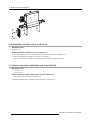
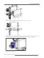
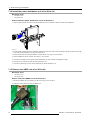
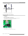
1
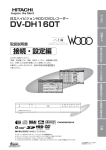
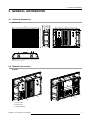
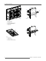
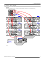
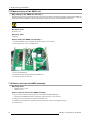
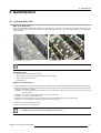
SLite Display
Service manual
R5976621/02
02/09/2005
Barco nv Events
Noordlaan 5, B-8520 Kuurne
Phone: +32 56.36.89.70
Fax: +32 56.36.88.24
E-mail: [email protected]
Visit us at the web: www.barco.com
Printed in Belgium
Changes
Barco provides this manual ’as is’ without warranty of any kind, either expressed or implied, including but not limited to the implied warranties or merchantability and fitness for a particular purpose. Barco may make improvements and/or changes to the product(s) and/or the
program(s) described in this publication at any time without notice.
This publication could contain technical inaccuracies or typographical errors. Changes are periodically made to the information in this
publication; these changes are incorporated in new editions of this publication.
Copyright ©
All rights reserved. No part of this document may be copied, reproduced or translated. It shall not otherwise be recorded, transmitted or
stored in a retrieval system without the prior written consent of Barco.
Guarantee and Compensation
Barco provides a guarantee relating to perfect manufacturing as part of the legally stipulated terms of guarantee. On receipt, the purchaser
must immediately inspect all delivered goods for damage incurred during transport, as well as for material and manufacturing faults Barco
must be informed immediately in writing of any complaints.
The period of guarantee begins on the date of transfer of risks, in the case of special systems and software on the date of commissioning,
at latest 30 days after the transfer of risks. In the event of justified notice of compliant, Barco can repair the fault or provide a replacement
at its own discretion within an appropriate period. If this measure proves to be impossible or unsuccessful, the purchaser can demand a
reduction in the purchase price or cancellation of the contract. All other claims, in particular those relating to compensation for direct or
indirect damage, and also damage attributed to the operation of software as well as to other services provided by Barco, being a component
of the system or independent service, will be deemed invalid provided the damage is not proven to be attributed to the absence of properties
guaranteed in writing or due to the intent or gross negligence or part of Barco.
If the purchaser or a third party carries out modifications or repairs on goods delivered by Barco, or if the goods are handled incorrectly,
in particular if the systems are commissioned operated incorrectly or if, after the transfer of risks, the goods are subject to influences not
agreed upon in the contract, all guarantee claims of the purchaser will be rendered invalid. Not included in the guarantee coverage are
system failures which are attributed to programs or special electronic circuitry provided by the purchaser, e.g. interfaces. Normal wear as
well as normal maintenance are not subject to the guarantee provided by Barco either.
The environmental conditions as well as the servicing and maintenance regulations specified in the this manual must be complied with by
the customer.
Trademarks
Brand and product names mentioned in this manual may be trademarks, registered trademarks or copyrights of their respective holders.
All brand and product names mentioned in this manual serve as comments or examples and are not to be understood as advertising for
the products or their manufactures.
Federal Communications Commission (FCC Statement)
This equipment has been tested and found to comply with the limits for a class A digital device, pursuant to Part 15 of the FCC rules.
These limits are designed to provide reasonable protection against harmful interference when the equipment is operated in a commercial
environment. This equipment generates, uses, and can radiate radio frequency energy and, if not installed and used in accordance with
the instruction manual, may cause harmful interference to radio communications. Operation of this equipment in a residential area may
cause harmful interference, in which case the user will be responsible for correcting any interference.
Table of contents
TABLE OF CONTENTS
1. Safety . . . . . . . . . . . . . . . . . . . . . . . . . . . . . . . . . . . . . . . . . . . . . . . . . . . . . . . . . . . . . . . . . . . . . . . . . . . . . . . . . . . . . . . . . . . . . . . . . . . . . . . . . . . . . . . . . . 3
1.1
Servicing safety instructions . . . . . . . . . . . . . . . . . . . . . . . . . . . . . . . . . . . . . . . . . . . . . . . . . . . . . . . . . . . . . . . . . . . . . . . . . . . . . . . . . . . . . . . . . . . . . . . . . . . . . . . . . . 3
2. General information. . . . . . . . . . . . . . . . . . . . . . . . . . . . . . . . . . . . . . . . . . . . . . . . . . . . . . . . . . . . . . . . . . . . . . . . . . . . . . . . . . . . . . . . . . . . . . . . . 5
2.1
2.2
2.3
2.4
SLite tile dimensions . . . . . . . . . . . . . . . . . . . . . . . . . . . . . . . . . . . . . . . . . . . . . . . . . . . . . . . . . . . . . . . . . . . . . . . . . . . . . . . . . . . . . . . . . . . . . . . . . . . . . . . . . . . . . . . . . .
Board & fan location. . . . . . . . . . . . . . . . . . . . . . . . . . . . . . . . . . . . . . . . . . . . . . . . . . . . . . . . . . . . . . . . . . . . . . . . . . . . . . . . . . . . . . . . . . . . . . . . . . . . . . . . . . . . . . . . . . .
Internal wiring diagram . . . . . . . . . . . . . . . . . . . . . . . . . . . . . . . . . . . . . . . . . . . . . . . . . . . . . . . . . . . . . . . . . . . . . . . . . . . . . . . . . . . . . . . . . . . . . . . . . . . . . . . . . . . . . . . .
Startup sequence of an SLite display system . . . . . . . . . . . . . . . . . . . . . . . . . . . . . . . . . . . . . . . . . . . . . . . . . . . . . . . . . . . . . . . . . . . . . . . . . . . . . . . . . . . . . . . .
5
5
7
8
3. Spare part and service kits for SLite displays . . . . . . . . . . . . . . . . . . . . . . . . . . . . . . . . . . . . . . . . . . . . . . . . . . . . . . . . . . . . . . . . 11
3.1
Spare part and service kits. . . . . . . . . . . . . . . . . . . . . . . . . . . . . . . . . . . . . . . . . . . . . . . . . . . . . . . . . . . . . . . . . . . . . . . . . . . . . . . . . . . . . . . . . . . . . . . . . . . . . . . . . . . 11
4. Troubleshooting check list of an SLite tile . . . . . . . . . . . . . . . . . . . . . . . . . . . . . . . . . . . . . . . . . . . . . . . . . . . . . . . . . . . . . . . . . . . . 13
4.1
4.2
4.3
4.4
4.5
4.6
4.7
No image on an SLite display. . . . . . . . . . . . . . . . . . . . . . . . . . . . . . . . . . . . . . . . . . . . . . . . . . . . . . . . . . . . . . . . . . . . . . . . . . . . . . . . . . . . . . . . . . . . . . . . . . . . . . . . 13
No image on an SLite tile. . . . . . . . . . . . . . . . . . . . . . . . . . . . . . . . . . . . . . . . . . . . . . . . . . . . . . . . . . . . . . . . . . . . . . . . . . . . . . . . . . . . . . . . . . . . . . . . . . . . . . . . . . . . 14
No image on SLite LED board . . . . . . . . . . . . . . . . . . . . . . . . . . . . . . . . . . . . . . . . . . . . . . . . . . . . . . . . . . . . . . . . . . . . . . . . . . . . . . . . . . . . . . . . . . . . . . . . . . . . . . . 15
No image on half SLite LED board . . . . . . . . . . . . . . . . . . . . . . . . . . . . . . . . . . . . . . . . . . . . . . . . . . . . . . . . . . . . . . . . . . . . . . . . . . . . . . . . . . . . . . . . . . . . . . . . . . 16
Swapped video content displayed on an SLite tile . . . . . . . . . . . . . . . . . . . . . . . . . . . . . . . . . . . . . . . . . . . . . . . . . . . . . . . . . . . . . . . . . . . . . . . . . . . . . . . . . . 16
Dark and bright LED’s. . . . . . . . . . . . . . . . . . . . . . . . . . . . . . . . . . . . . . . . . . . . . . . . . . . . . . . . . . . . . . . . . . . . . . . . . . . . . . . . . . . . . . . . . . . . . . . . . . . . . . . . . . . . . . . . 16
Fan fail. . . . . . . . . . . . . . . . . . . . . . . . . . . . . . . . . . . . . . . . . . . . . . . . . . . . . . . . . . . . . . . . . . . . . . . . . . . . . . . . . . . . . . . . . . . . . . . . . . . . . . . . . . . . . . . . . . . . . . . . . . . . . . . . 16
5. On Screen Display messages . . . . . . . . . . . . . . . . . . . . . . . . . . . . . . . . . . . . . . . . . . . . . . . . . . . . . . . . . . . . . . . . . . . . . . . . . . . . . . . . . . . . 19
5.1
OSD messages. . . . . . . . . . . . . . . . . . . . . . . . . . . . . . . . . . . . . . . . . . . . . . . . . . . . . . . . . . . . . . . . . . . . . . . . . . . . . . . . . . . . . . . . . . . . . . . . . . . . . . . . . . . . . . . . . . . . . . . 19
6. Servicing an SLite tile . . . . . . . . . . . . . . . . . . . . . . . . . . . . . . . . . . . . . . . . . . . . . . . . . . . . . . . . . . . . . . . . . . . . . . . . . . . . . . . . . . . . . . . . . . . . . 25
6.1
6.2
6.3
6.4
6.5
6.6
6.7
Replace the re-sync unit of an SLite tile . . . . . . . . . . . . . . . . . . . . . . . . . . . . . . . . . . . . . . . . . . . . . . . . . . . . . . . . . . . . . . . . . . . . . . . . . . . . . . . . . . . . . . . . . . . . . 25
Replace the SMPS assembly of an SLite tile . . . . . . . . . . . . . . . . . . . . . . . . . . . . . . . . . . . . . . . . . . . . . . . . . . . . . . . . . . . . . . . . . . . . . . . . . . . . . . . . . . . . . . . 25
Replace the LED assembly of an SLite tile. . . . . . . . . . . . . . . . . . . . . . . . . . . . . . . . . . . . . . . . . . . . . . . . . . . . . . . . . . . . . . . . . . . . . . . . . . . . . . . . . . . . . . . . . . 25
Replace the controller unit of an SLite tile. . . . . . . . . . . . . . . . . . . . . . . . . . . . . . . . . . . . . . . . . . . . . . . . . . . . . . . . . . . . . . . . . . . . . . . . . . . . . . . . . . . . . . . . . . . 26
Replace the power distribution unit of an SLite tile . . . . . . . . . . . . . . . . . . . . . . . . . . . . . . . . . . . . . . . . . . . . . . . . . . . . . . . . . . . . . . . . . . . . . . . . . . . . . . . . . 26
Replace the SMPS unit of an SLite tile . . . . . . . . . . . . . . . . . . . . . . . . . . . . . . . . . . . . . . . . . . . . . . . . . . . . . . . . . . . . . . . . . . . . . . . . . . . . . . . . . . . . . . . . . . . . . . 26
Replace a fan of the SMPS assembly . . . . . . . . . . . . . . . . . . . . . . . . . . . . . . . . . . . . . . . . . . . . . . . . . . . . . . . . . . . . . . . . . . . . . . . . . . . . . . . . . . . . . . . . . . . . . . . 26
7. SLite servicing procedures . . . . . . . . . . . . . . . . . . . . . . . . . . . . . . . . . . . . . . . . . . . . . . . . . . . . . . . . . . . . . . . . . . . . . . . . . . . . . . . . . . . . . . . 29
7.1
7.2
7.3
7.4
7.5
7.6
7.7
7.8
7.9
7.10
7.11
7.12
7.13
7.14
7.15
7.16
7.17
7.18
Remove the resync-unit of an SLite tile . . . . . . . . . . . . . . . . . . . . . . . . . . . . . . . . . . . . . . . . . . . . . . . . . . . . . . . . . . . . . . . . . . . . . . . . . . . . . . . . . . . . . . . . . . . . . 29
Install the re-sync unit . . . . . . . . . . . . . . . . . . . . . . . . . . . . . . . . . . . . . . . . . . . . . . . . . . . . . . . . . . . . . . . . . . . . . . . . . . . . . . . . . . . . . . . . . . . . . . . . . . . . . . . . . . . . . . . . 29
Remove the back cover of an SLite tile . . . . . . . . . . . . . . . . . . . . . . . . . . . . . . . . . . . . . . . . . . . . . . . . . . . . . . . . . . . . . . . . . . . . . . . . . . . . . . . . . . . . . . . . . . . . . 30
Install the back cover of an SLite tile . . . . . . . . . . . . . . . . . . . . . . . . . . . . . . . . . . . . . . . . . . . . . . . . . . . . . . . . . . . . . . . . . . . . . . . . . . . . . . . . . . . . . . . . . . . . . . . . 32
Remove the SMPS assembly of an SLite tile . . . . . . . . . . . . . . . . . . . . . . . . . . . . . . . . . . . . . . . . . . . . . . . . . . . . . . . . . . . . . . . . . . . . . . . . . . . . . . . . . . . . . . . 33
Install the SMPS assembly of an SLite tile . . . . . . . . . . . . . . . . . . . . . . . . . . . . . . . . . . . . . . . . . . . . . . . . . . . . . . . . . . . . . . . . . . . . . . . . . . . . . . . . . . . . . . . . . . 34
Remove a LED assembly of an SLite tile. . . . . . . . . . . . . . . . . . . . . . . . . . . . . . . . . . . . . . . . . . . . . . . . . . . . . . . . . . . . . . . . . . . . . . . . . . . . . . . . . . . . . . . . . . . . 34
Install a LED assembly in an SLite tile . . . . . . . . . . . . . . . . . . . . . . . . . . . . . . . . . . . . . . . . . . . . . . . . . . . . . . . . . . . . . . . . . . . . . . . . . . . . . . . . . . . . . . . . . . . . . . 36
Remove the controller unit of an SLite tile. . . . . . . . . . . . . . . . . . . . . . . . . . . . . . . . . . . . . . . . . . . . . . . . . . . . . . . . . . . . . . . . . . . . . . . . . . . . . . . . . . . . . . . . . . . 37
Install the controller unit of an SLite tile . . . . . . . . . . . . . . . . . . . . . . . . . . . . . . . . . . . . . . . . . . . . . . . . . . . . . . . . . . . . . . . . . . . . . . . . . . . . . . . . . . . . . . . . . . . . . 38
Remove the power distribution unit of an SLite tile . . . . . . . . . . . . . . . . . . . . . . . . . . . . . . . . . . . . . . . . . . . . . . . . . . . . . . . . . . . . . . . . . . . . . . . . . . . . . . . . . 38
Install the power distribution unit of an SLite tile . . . . . . . . . . . . . . . . . . . . . . . . . . . . . . . . . . . . . . . . . . . . . . . . . . . . . . . . . . . . . . . . . . . . . . . . . . . . . . . . . . . . 40
Remove the SMPS unit of an SLite tile. . . . . . . . . . . . . . . . . . . . . . . . . . . . . . . . . . . . . . . . . . . . . . . . . . . . . . . . . . . . . . . . . . . . . . . . . . . . . . . . . . . . . . . . . . . . . . 40
Install the SMPS unit of an SLite tile . . . . . . . . . . . . . . . . . . . . . . . . . . . . . . . . . . . . . . . . . . . . . . . . . . . . . . . . . . . . . . . . . . . . . . . . . . . . . . . . . . . . . . . . . . . . . . . . 41
Manual startup of the SMPS unit . . . . . . . . . . . . . . . . . . . . . . . . . . . . . . . . . . . . . . . . . . . . . . . . . . . . . . . . . . . . . . . . . . . . . . . . . . . . . . . . . . . . . . . . . . . . . . . . . . . . 42
Remove fan from the SMPS assembly . . . . . . . . . . . . . . . . . . . . . . . . . . . . . . . . . . . . . . . . . . . . . . . . . . . . . . . . . . . . . . . . . . . . . . . . . . . . . . . . . . . . . . . . . . . . . . 42
Install a fan on the SMPS assembly . . . . . . . . . . . . . . . . . . . . . . . . . . . . . . . . . . . . . . . . . . . . . . . . . . . . . . . . . . . . . . . . . . . . . . . . . . . . . . . . . . . . . . . . . . . . . . . . . 43
Removing an SLite tile . . . . . . . . . . . . . . . . . . . . . . . . . . . . . . . . . . . . . . . . . . . . . . . . . . . . . . . . . . . . . . . . . . . . . . . . . . . . . . . . . . . . . . . . . . . . . . . . . . . . . . . . . . . . . . . 43
8. Maintenance. . . . . . . . . . . . . . . . . . . . . . . . . . . . . . . . . . . . . . . . . . . . . . . . . . . . . . . . . . . . . . . . . . . . . . . . . . . . . . . . . . . . . . . . . . . . . . . . . . . . . . . . . 47
8.1
Cleaning SLite tiles. . . . . . . . . . . . . . . . . . . . . . . . . . . . . . . . . . . . . . . . . . . . . . . . . . . . . . . . . . . . . . . . . . . . . . . . . . . . . . . . . . . . . . . . . . . . . . . . . . . . . . . . . . . . . . . . . . . 47
Index. . . . . . . . . . . . . . . . . . . . . . . . . . . . . . . . . . . . . . . . . . . . . . . . . . . . . . . . . . . . . . . . . . . . . . . . . . . . . . . . . . . . . . . . . . . . . . . . . . . . . . . . . . . . . . . . . . . . . . 49
R5976621 SLITE DISPLAY 02/09/2005
1
Table of contents
2
R5976621 SLITE DISPLAY 02/09/2005
1. Safety
1. SAFETY
1.1 Servicing safety instructions
WARNING:
Servicing must be done by authorized and qualified technical personnel only, which are thoroughly familiar with the product and all of the proper safety checks of this product.
Personal Protection
Image 1-1
Warning
Image 1-2
Suspended Loads
Image 1-3
Hard Hat
Image 1-4
Mind Your Fingers
When servicing on site be aware of suspended loads, wear a hard hat to reduce the risk of personal injury. Mind your fingers while
working with heavy loads.
Safety precautions:
•
Follow all servicing and safety instructions mentioned in the servicing procedures.
•
Unplug the tile AC power cord from the AC power source and wait about 10 minutes before start any servicing to the tile. This
to allow the capacitors to discharge.
•
Some boards contains electrostatically sensitive devices (ESD). Take the necessary precautions to prevent the incidence of
component damage caused by static electricity.
•
Do not modify and/or replicate any component. BARCO uses specific materials and manufacturing processes in order to
achieve part strength. No other parts then BARCO parts are allowed.
Additional on-site servicing safety precautions:
•
Fence off a restricted area of at least 3 meters around the LED-wall using an eye-catching fence and “KEEP OUT” signs. This
to prevent unauthorized persons come near the LED-wall during servicing.
•
Inspect the complete LED-wall for security, wear, deformation, corrosion, and any other circumstances that may effect the load
handling capability of the part.
•
Check the handles on the back of the tiles for loss of strength due to exposing to environmental conditions. Replace damaged
handles immediately before starting any servicing to the tiles.
•
In case of removing a tile out of the LED-wall, ensure the tile is secured with a safety cable to the LED-wall structure.
•
In case of replacing a LED assembly of an SLite tile, ensure the LED assembly is secured with a safety cable to the SLite frame.
•
Take the necessary precautions to prevent water intrusion inside the tile due to weather conditions.
R5976621 SLITE DISPLAY 02/09/2005
3
1. Safety
4
R5976621 SLITE DISPLAY 02/09/2005
2. General information
2. GENERAL INFORMATION
2.1 SLite tile dimensions
Dimensions
253,7
710
560
189,6
672
896
Image 2-1
Dimensions given in millimeters.
2.2 Board & fan location
Location
B
C
Image 2-2
•
A. Re-sync unit.
•
B. External fan.
•
C. SMPS assembly.
A
R5976621 SLITE DISPLAY 02/09/2005
5
2. General information
H
G
F
F
D
E
Image 2-3
•
D. LED assembly.
•
E. Controller unit.
•
F. Small fan SMPS assembly.
•
G. Power distribution unit.
•
H. SMPS unit.
K
I
J
K
Image 2-4
6
•
I. LED board.
•
J. LED driver unit.
•
K. Large fan SMPS assembly.
R5976621 SLITE DISPLAY 02/09/2005
2. General information
2.3 Internal wiring diagram
Diagram
Internal wiring between LED drivers, controller and power distribution unit (seen from the back of the SLite tile)
Image 2-5
R5976621 SLITE DISPLAY 02/09/2005
7
2. General information
Fan interconnections
Image 2-6
2.4 Startup sequence of an SLite display system
The first two steps of the startup sequence are done manually.
Startup sequence:
1. Switch on the main power to the SLite tiles.
Note: Nothing happens yet.
2. Power up the digitizer.
-
The digitizer generates a START signal for the first tile.
-
The digitizer places video content, of the last selected input slot, on the data line to the LED display.
3. The START signal triggers the resync-unit of the first tile to start up on the line voltage provided on the data cable.
-
The resync-unit transfers the START signal to an ON signal for the local SMPS.
-
The green LED on the resync-unit remains off.
-
The red LED on the resync-unit will only light up in case there is no video content present on the incoming data line.
-
The resync-unit delays the START signal about half a second before sending it to the next tile. This is necessary to reduce
the inrush current of the complete SLite display. This delayed START signal will activate the next tile and so on.
4. The ON signal from the resync-unit triggers the local SMPS to start up.
-
The four internal fans starts to turn.
5. The power distribution unit starts up.
-
The power distribution unit generates +15V and +8V.
-
The +15V red LED and the +8V red LED goes on.
6. The controller unit starts up.
-
The controller unit generates the local +5V and the local +8V line voltage.
-
The +5V red LED on the controller unit goes on.
-
The local +8V line voltage supports the line voltage on the data cable to supply the resync-unit.
-
The presence of the local +8V line voltage on the resync-unit lights up the green LED on the resync-unit.
7. The controller unit starts to initialize.
8
-
The yellow LED on the controller unit lights up continuously.
-
The green LED’s on the controller unit starts lighting up after the FPGA’s are configured.
-
The Yellow LED on the controller unit starts to flash (half a second on, half a second off) indicating the controller is completely
and correctly initialized.
R5976621 SLITE DISPLAY 02/09/2005
2. General information
8. The LED driver receives data from the controller.
-
The yellow LED on the LED drivers goes on.
9. The SLite tile shows video content.
R5976621 SLITE DISPLAY 02/09/2005
9
2. General information
10
R5976621 SLITE DISPLAY 02/09/2005
3. Spare part and service kits for SLite displays
3. SPARE PART AND SERVICE KITS FOR SLITE
DISPLAYS
3.1 Spare part and service kits
General:
Barco provides several kits for servicing SLite tiles. Below you find an order list of existing SLite spare part and service kits. In the
future new SLite kits can be added to this list. Contact Barco n.v. to get an updated list.
Order info:
Article No.
Description
R9851820
One SLite 14 LED assembly (LED board + LED driver).
R9851830
One SLite 10 LED assembly (LED board + LED driver).
R9852030
SLite 14 spare pack.
Contains two SLite 14 LED assemblies, one complete SMPS assembly, one complete re-sync unit, a set of
screws, data and power cables, two handles, O-rings and fan cover for the external fan.
R9852020
SLite 10 spare pack.
Contains two SLite 10 LED-board assemblies, one complete SMPS assembly, one complete re-sync unit, a set
of screws, data and power cables, two handles, O-rings and fan cover for the external fan.
R9852960
SLite 22 spare pack.
Contains two SLite 22 LED-board assemblies, one complete SMPS assembly, one complete re-sync unit, a set
of screws, data and power cables, two handles, O-rings and fan cover for the external fan.
R9852010
SLite tooling kit.
Contains all, standard and SLite specific, tools required for optimal installation and servicing.
R9852050
SLite steel calibration kit.
Includes a small and large caliber used for correct positioning of the SLite mounting plates for fixed installations.
R9851310
Shader repair kit.
R9850650
LED replacement kit.
R763178
Complete re-sync unit (housing included).
B557232
SLite SMPS unit (without mechanical frame and fans).
R764130
SLite power distribution unit.
R764099
SLite controller unit.
B3246221D
External fan.
B3245422D
Large SMPS fan.
B3245312D
Small SMPS fan for the right side of the SMPS assembly (with long wire unit).
B3245313D
Small SMPS fan for the left side of the SMPS assembly (with short wire unit).
R5976621 SLITE DISPLAY 02/09/2005
11
3. Spare part and service kits for SLite displays
12
R5976621 SLITE DISPLAY 02/09/2005
4. Troubleshooting check list of an SLite tile
4. TROUBLESHOOTING CHECK LIST OF AN SLITE TILE
Overview
•
No image on an SLite display
•
No image on an SLite tile.
•
No image on SLite LED board
•
No image on half SLite LED board
•
Swapped video content displayed on an SLite tile
•
Dark and bright LED’s
•
Fan fail.
4.1 No image on an SLite display
Check list:
Situation
Solution
SLite tiles are not energized.
1.
Check if the power source is energized.
2.
Check if the power cord is well connected between the power source and
the LED-wall.
3.
Check the power distribution network of the SLite display system.
Digitizer is not energized.
Switch on the digitizer.
Fiberlink Transmitter is not energized.
Switch on the Fiberlink Transmitter.
Fiberlink Receiver is not energized.
Connect the Fiberlink Receiver with the power circuit of the LED-wall.
Wrong Digitizer settings in XLite toolset.
Check the Digitizer settings in the XLite toolset:
The “Output selection” of the Digitizer must be set to : “Barco LED Wall” .
The “Start system LED-wall” must be set to : “ON” .
Wrong Digitizer timings set in XLite
toolset.
See user guide of the XLite toolset to determine the correct timings or use the
wizard in the XLite toolset program.
Error message on LCD status display of
the Fiberlink Transmitter.
See installation manual of the Fiberlink Transmitter to resolve the problem.
A video signal with black content is
applied to the selected input slot of the
Digitizer.
Apply another video signal to the selected input slot or select another input slot
that does not contain black content.
LED-wall receives no data signal from
Digitizer.
Check all data connections between Digitizer and LED-wall.
Malfunction re-sync unit of the first tile in
the LED-wall.
Replace the re-sync unit of the first tile in the LED-wall. See page 25.
Malfunction Digitizer.
Replace the Digitizer.
R5976621 SLITE DISPLAY 02/09/2005
Note that the message “RX-TX MISMATCHED OK” is not an error. This message
indicates that the fiberlink transmitter and receiver are not mismatched.
13
4. Troubleshooting check list of an SLite tile
4.2 No image on an SLite tile.
Check list:
Situation
Solution
SLite tile has no power.
1.
Plug in the power cords and lock the plug holder clamps firmly.
2.
Switch on the main power to the SLite tiles.
3.
Be sure the power source is energized.
SLite tile receives no data.
Plug in the data cables and lock the plug holder clamps firmly.
Controller unit receives no data from the
resync-unit.
Check if the flat cable between the re-sync unit and controller is plugged in.
Controller unit has no power.
Check if the 8 pins yellow cable between the power distribution unit and controller
unit is plugged in.
LED drivers receive no data from the
controller unit.
Check if the flat cables between the LED drivers and the controller unit are
plugged in.
LED drivers have no power.
Check if all black power cables between the power distribution unit and the LED
drivers are plugged in.
No sync present on the incoming signal.
1.
Make sure that the digitizer works properly and the correct input slot is
selected.
2.
Be sure a proper input signal is applied to the selected input slot of the
digitizer.
3.
Try an other input slot of the digitizer. If the problem remains, check the
operation of the digitizer.
1.
Be sure the internal power cable between re-sync unit and SMPS is plugged
in.
2.
Place a jumper link on JP1 of the SMPS to start up the SMPS without ON
signal from the resync-unit. In case the SMPS starts-up, noticeable by
the internal fans which turns, replace the resync-unit (see page 25) and
remove the jumper link from the SMPS. Otherwise replace the SMPS unit
(see page 26).
The “+15V” red LED doesn’t lights up
while the internal fans still turns.
1.
The +15V power supply on the power
distribution unit is overloaded due to a
short circuit on one of the LED drivers.
Disconnect all power connections to the LED drivers. When the +15V red
LED doesn’t lights up replace the power distribution unit (see page 26) else
go on with the next solution.
2.
Try to power up the LED drivers one by one by placing back the black power
cables. Do this from bottom LED driver to top LED driver and from left to right
until the +15V red LED doesn’t lights up. Replace the last connected LED
assembly which make the +15V supply overloaded. See page 25.
The “+8V” red LED flashes while the
internal fans still turns.
1.
Disconnect all power connections to the LED drivers and controller unit.
When the +8V supply has “hiccups” again replace the power distribution unit
(see page 26) else go on with the next solution.
2.
Place the power connection back between controller unit and power
distribution unit (8 pins yellow wire unit) to power up the controller. In case
the +8V supply starts to “hiccup” again replace the controller unit (see page
26) else go on with the next solution.
3.
Try to power up the LED drivers one by one by placing back the black power
cables. Do this from bottom LED driver to top LED driver and from left to right
until the +8V supply starts to “hiccup” again. Replace the last connected LED
assembly which make the +8V supply to “hiccup”. See page 25.
Red LED on the resync-unit flashes.
SLite SMPS doesn’t start up.
Internal fans do not turn.
The +8V power supply on the power
distribution unit has “hiccups” due to a
short circuit somewhere inside the SLite
tile.
Malfunction of the power distribution unit.
Replace the power distribution unit. See page 26.
Both red LED’s on the power distribution
unit does not light up but the internal fans
still turns.
14
R5976621 SLITE DISPLAY 02/09/2005
4. Troubleshooting check list of an SLite tile
Situation
Solution
The SLite SMPS has “hiccups”.
1.
SMPS tries to start up but fails repeatedly
due to a short circuit somewhere inside
the SLite tile. The red LED’s on the power
distribution unit flashes. The four internal
fans don’t turn.
Remove the power distribution unit (see page 38), so the SMPS can start up
unloaded. If the “hiccups” remains (this is audible) replace the SMPS unit
(see page 26) else go on with the next solution.
2.
Place the power distribution unit back (see page 40) but disconnect all
power connections to the LED drivers and controller unit. When the SMPS
has “hiccups” again replace the power distribution unit (see page 26) else
go on with the next solution.
3.
Place the power connection back between controller unit and power
distribution unit (8 pins yellow wire unit) to power up the controller. In case
the SMPS starts to “hiccup” again replace the controller unit (see page 26)
else go on with the next solution.
4.
Try to power up the LED drivers one by one by placing back the black power
cables. Do this from bottom LED driver to top LED driver and from left to right
until the SMPS starts to “hiccup” again. Replace the last connected LED
assembly which make the SMPS to “hiccup”. See page 25.
Program code not correct programmed.
Update program code. See software manual XLite toolset.
Yellow LED on the controller unit flashes
fast.
FPGA’s not running because external
flash not programmed. Yellow LED on the
controller unit flashes half a second on
and two seconds off.
Update firmware front and firmware back. See software manual XLite toolset. In
case firmware update does not help replace the controller unit. See page 26.
Undefined error during configuration of
FPGA’s. Yellow LED on the controller unit
flashes 2,5 seconds on and 0,5 second
off.
Update firmware front and firmware back. See software manual XLite toolset. In
case firmware update does not help replace the controller unit. See page 26.
Watchdog FPGA’s not responding due
to malfunctioning FPGA’s. Yellow LED
on the controller unit flashes 0,1 second
on – 0,1 second off – 0,1 second on – 2
seconds off.
Update firmware front and firmware back. See software manual XLite toolset. In
case firmware update does not help replace the controller unit. See page 26.
All previous situations are OK. So,
probably the resync-unit is not working
properly.
Replace the resync-unit. See page 25.
4.3 No image on SLite LED board
Check list:
Situation
Solution
SLite LED assembly has no power.
Ensure the black wire unit between the power distribution unit and the LED driver
is plugged in.
SLite LED driver receives no data.
Ensure the flat cable from the controller or from the previous LED driver is
plugged in.
Malfunction LED driver.
Replace the complete LED assembly. See page 25.
R5976621 SLITE DISPLAY 02/09/2005
15
4. Troubleshooting check list of an SLite tile
4.4 No image on half SLite LED board
Check list:
Situation
Solution
The factory calibration values in the
memory chip of the SLite LED board are
last.
The SLite LED assembly must send back to Barco for reloading the calibration
values.
Replace the complete LED assembly. See page 25.
4.5 Swapped video content displayed on an SLite tile
Check list:
Situation
Solution
The left LED drivers receive video content
for the right LED drivers and vice versa.
Swap the two flat cables on the controller unit.
4.6 Dark and bright LED’s
Check list:
Situation
Solution
A cluster of LED’s of the same color lights
up continuously or never lights up.
Replace the LED assembly where this problem arise. See page 25
Several LED’s grouped in the same
column or row never lights up.
Replace the LED assembly where this problem arise. See page 25
One green LED never lights up.
Replace the green LED. Use the “DLite LED replacement kit” to do so (R9850560).
One blue LED never lights up.
In case of an SLite 10 tile: The bleu LED is probably broken. Replace it. Use the
“DLite LED replacement kit” to do so (R9850560).
In case of an SLite 14 tile: There is a failure with the “constant current drive” or
the blue LED is broken. Replace the LED driver (temporally) of the LED assembly
with a good working LED driver and check if the blue LED is working now. If the
LED is working place the original LED driver back and replace the complete LED
assembly (LED board + LED driver), see page 25. Otherwise replace the blue
LED with the “DLite LED replacement kit” (R9850560) and place the original
LED driver back.
Two red LED’s of one pixel never lights
up while the red LED’s of the neighboring
pixels operate normally.
In case of an SLite 10 tile: one or both LED’s are probably broken. Replace both
LED’s. Use the “DLite LED replacement kit” to do so (R9850560).
In case of an SLite 14 tile: There is a failure with the “constant current drive”
or one of the LED’s is broken. Replace the LED driver (temporally) of the LED
assembly with a good working LED driver and check if the LED’s are working
now. If the LED’s are working place the original LED driver back and replace the
complete LED assembly (LED board + LED driver), see page 25. Otherwise
replace both LED’s with the “DLite LED replacement kit” (R9850560) and place
the original LED driver back.
4.7 Fan fail.
The external fan is only activated in case the internal temperature exceed a specific temperature. The fan fail
detection on the external fan is only working in case the external fan is activated. The fan fail detection on the
internal fans works continuously.
16
R5976621 SLITE DISPLAY 02/09/2005
4. Troubleshooting check list of an SLite tile
Check list:
Situation
Solution
Message displayed repeatedly:
1.
!!!!
FAN
FAIL
R5976621 SLITE DISPLAY 02/09/2005
Check if all fans are connected with the power distribution unit. Four internal
fans and one external fan.
2.
Be sure that no fans are blocked.
3.
Replace non turning internal fans.
4.
In case all internal fans are turning and the message remains, try to power
up the external fan by switching the connection of the external fan with one of
the internal fans on the power distribution unit. When this fan fails replace it
else replace the power distribution unit (see page 26).
17
4. Troubleshooting check list of an SLite tile
18
R5976621 SLITE DISPLAY 02/09/2005
5. On Screen Display messages
5. ON SCREEN DISPLAY MESSAGES
General
An SLite tile can generate and display several “On Screen Display” (OSD) messages regarding parameter statuses of the tile. Most
of those messages can be displayed on request via the XLite toolset. Other OSD messages are automatically displayed in case an
error occurred. Those error messages are displayed in red. Most OSD messages are displayed for a time period of 10 seconds
or continuous, depending the XLite toolset settings. Some are displayed for a time period of 3 seconds and repeated after a time
interval of 25 seconds.
5.1 OSD messages
List with OSD messages:
OSD
message
Description
SOFT
Displaying of software version flash-code (normal working program) and software version boot-code.
1.01
Software versions can be displayed on request via the XLite toolset.
BOOT
1.0
FIRM
Displaying of software version firmware front-FPGA, firmware back-FPGA and firmware re-sync unit.
B1.02
Firmware versions can be displayed on request via the XLite toolset.
C1.01
01.02
FIRM
Displaying of software version firmware front-FPGA, firmware back-FPGA.
B1.02
I 2C error while reading firmware re-sync unit or feature not available.
C1.01
Firmware versions can be displayed on request via the XLite toolset.
XX.XX
ADDR.
14
Displaying tile address. Note that all devices in the data chain has an address number, starting with the master
digitizer having address “1”. The address number increments for all following devices in the data chain.
Each digitizer, fiberlink transmitter, fiberlink receiver, AEC and all tiles in the data chain are considered as a
device with a unique address.
Address number of the tile can be displayed on request via the XLite toolset.
TEMP.
Displaying the temperature inside the tile in degrees Celsius and degrees Fahrenheit.
34°C
Tile temperature can be displayed on request via the XLite toolset.
93°F
DCONT
R 36
G 36
Displaying the RGB values set for digital contrast. These values can be changed between 0 and 255 using
the XLite toolset.
Digital contrast values can be displayed on request via the XLite toolset.
B 36
ACONT
Displaying the RGB values set for analog contrast. These values are factory pre-adjusted.
R 850
Analog contrast values can be displayed on request via the XLite toolset.
G 800
B 600
HPOS
370
→
Displaying the start pixel row and end pixel row of the tile in the complete LED-wall. The origin is always
left top of the display.
The horizontal window position can be displayed on request via the XLite toolset.
434
R5976621 SLITE DISPLAY 02/09/2005
19
5. On Screen Display messages
OSD
message
Description
VPOS
Displaying the start pixel column and end pixel column of the tile in the complete LED-wall. The origin is
always left top of the display.
146
→
The vertical window position can be displayed on request via the XLite toolset.
194
RUN
Displaying the total run time of the tile in hours.
TIME
The total run time of a tile can be displayed on request via the XLite toolset.
71
H.
RUN
Run time exceeds 99.999 hours. (Buy a new LED-wall).
TIME
99999
SER.
Displaying the serial number of the tile.
NR.
The serial number of the tile can be displayed on request via the XLite toolset.
0126
4529
PWM-R
Displaying PWM-repeat value and MA-clock value of the tile. PWM-R is factory pre-adjusted.
6
This message can be displayed on request via the XLite toolset.
MA-CL
60
SYNC
Displaying status re-sync unit: re-sync unit works properly and sync signal is detected.
OK
The status of the re-sync unit can be displayed on request via the XLite toolset.
NO
Displaying status re-sync unit: re-sync unit works properly but no sync signal is detected.
SYNC
The status of the re-sync unit can be displayed on request via the XLite toolset.
RESYN
Displaying status re-sync unit: malfunction re-sync unit.
NOT
The status of the re-sync unit can be displayed on request via the XLite toolset.
OK
NO
I 2C error while reading status re-sync unit or re-sync unit does not support this feature (older re-sync units).
RESYN
The status of the re-sync unit can be displayed on request via the XLite toolset.
FOUND
EXT
Displaying status external fan: external fan is on.
FAN
The status of the external fan can be displayed on request via the XLite toolset.
ON
EXT
Displaying status external fan: external fan is off.
FAN
The status of the external fan can be displayed on request via the XLite toolset.
OFF
RS232
Displaying the current RS232 speed which value is set to 19200 baud.
SPEED
The baud rate can be displayed on request via the XLite toolset.
19200
baud
RS232
Displaying the current RS232 speed which value is set to 38400 baud.
SPEED
The baud rate can be displayed on request via the XLite toolset.
38400
baud
20
R5976621 SLITE DISPLAY 02/09/2005
5. On Screen Display messages
OSD
message
Description
RS232
Displaying the current RS232 speed which value is set to 57600 baud.
SPEED
The baud rate can be displayed on request via the XLite toolset.
57600
baud
RS232
Displaying the current RS232 speed which value is set to 115,2 kilo baud.
SPEED
The baud rate can be displayed on request via the XLite toolset.
115.2
Kbaud
MEAS
Displaying detected measurement systems: All tiles use measurement system 10.
SYST
This message can be displayed on request via the XLite toolset.
ALL
10
MEAS
SYST
15-
Displaying detected measurement systems: Different measurement system detected. Displaying minimum
and maximum measurement system.
The minimum and maximum measurement systems can be displayed on request via the XLite toolset.
17
ALL
Both calibration corrections, luma (white balance) and color (RGB), are disabled.
CALI
This message is displayed each time the tile starts up and all calibrations are set to disabled.
DISABLED
COLOR
Color (RGB) calibration correction is disabled.
CALI
This message is displayed each time the tile starts up and only the color calibration is set to disabled.
DISABLED
COLOR
Color calibration correction does not exist.
CALI
This message is displayed each time the tile starts up and all calibrations are set to enabled, but no correction
values are found for color calibration.
DON’T
EXIST
CALI
Displaying calibration status: Only luma (white balance) correction enabled
ONLY
Calibration status can be displayed on request via the XLite toolset.
LUMA
CALI
LUMA
NOCOL
Displaying calibration status: Both corrections, luma (white balance) and color (RGB), are enabled. But
no correction values are found for color calibration.
Calibration status can be displayed on request via the XLite toolset.
EXIST
CALI
Displaying calibration status: Both calibration corrections, luma (white balance) and color (RGB), are disabled.
DISA-
Calibration status can be displayed on request via the XLite toolset.
BLED
CALI
FULL
LEDB.
Displaying calibration status: Both corrections, luma (white balance) and color (RGB), are enabled. The color
corrections are calculated with the LED-board measurements.
Calibration status can be displayed on request via the XLite toolset.
BASED
R5976621 SLITE DISPLAY 02/09/2005
21
5. On Screen Display messages
OSD
message
Description
CALI
Displaying calibration status: Both corrections, luma (white balance) and color (RGB), are enabled. The color
corrections are calculated with individual LED (pixel) measurements.
FULL
INDIV
Calibration status can be displayed on request via the XLite toolset.
BASED
FRAME
Displaying frame counter (S0008275) of LED assembly (3).
CNT 3
The frame counter can be displayed on request via the XLite toolset per LED assembly.
S000
8275
!!!!
FAN
One or more fans (internal or external) are failing. This message is displayed for a time period of 3 seconds
and repeated every 25 seconds.
FAIL
Service intervention is required. Ignoring this message will result in more parts of the tile being permanent
damaged.
FRONT
Firmware front-FPGA update message.
25%
BACK
Firmware back-FPGA update message.
25%
DONE
Message indicating that the software or firmware update is successfully.
ERROR
Message indicating that the software or firmware update is failed.
WRONG
Wrong file selected in the XLite toolset for software or firmware update.
FILE
CHECK
Checksum-error in software or firmware update.
SUM
ERROR
START
Calibration starts.
CALI
CALI
Calibration is done successfully.
DONE
SAVE
Calculated calibration corrections are being saved.
CALI
BOARD
The LED board and LED driver have the same frame counter.
MATCH
The LED board–driver match can be displayed on request via the XLite toolset
BOARD
Different frame counters detected between the LED driver and LED board for the following LED assemblies
(in this case LED assembly 1, 3 and 6).
SWAP
1-3-6
FRAME
EMPTY
4-5
FRAME
The LED board–driver match can be displayed on request via the XLite toolset
No frame counter found in some LED drivers or LED boards for the following LED assemblies (in this case
LED assembly 4 and 5). Calibration measurements probably not existing.
The LED board–driver match can be displayed on request via the XLite toolset
I 2C error occurred while reading frame counter of LED assembly 3.
CNT 3
I2CERROR
22
R5976621 SLITE DISPLAY 02/09/2005
5. On Screen Display messages
OSD
message
Description
TEMP.
I 2C error occurred while reading the temperature value of the tile.
I2CERROR
RUN
I 2C error occurred while reading the total run time of the tile.
TIME
I2CERROR
DCONT
I 2C error occurred while reading the digital contrast values of the tile.
I2CERROR
ACONT
I 2C error occurred while reading the analog contrast values of the tile.
I2CERROR
HPOS
I 2C error occurred while reading the horizontal position values of the tile.
I2CERROR
VPOS
I 2C error occurred while reading the vertical position values of the tile.
I2CERROR
PWM-R
I 2C error occurred while reading PWM-repeat and MA-clock of the tile.
MA-CL
I2CERROR
MEAS
I 2C error occurred while reading the EEPROM of the LED-driver.
SYST
I2CERROR
SER.
I 2C error occurred while reading serial number of the tile.
NR.
I2CERROR
CALI
I 2C error occurred while reading the EEPROM on the controller unit, during calibration.
I2CERROR
R5976621 SLITE DISPLAY 02/09/2005
23
5. On Screen Display messages
24
R5976621 SLITE DISPLAY 02/09/2005
6. Servicing an SLite tile
6. SERVICING AN SLITE TILE
6.1 Replace the re-sync unit of an SLite tile
How to replace the re-sync unit of an SLite tile ?
1. Ensure you understand and follow the “Servicing safety instruction” on page 3.
2. Remove the re-sync unit, see "Remove the resync-unit of an SLite tile", page 29.
3. Install the new re-sync unit, see "Install the re-sync unit", page 29.
4. Reconnect the power and data cables to the re-sync unit.
Caution: Make sure that all plug holder clamps are locked firmly. Dummy plugs must be placed on unused connection ports.
A
Image 6-1
A
Plug holder clamp
6.2 Replace the SMPS assembly of an SLite tile
How to replace the SMPS assembly of an SLite tile ?
1. Ensure you understand and follow the “Servicing safety instruction” on page 3.
2. Open the back cover of the SLite tile, see "Remove the back cover of an SLite tile", page 30.
3. Remove the SMPS assembly, see "Remove the SMPS assembly of an SLite tile", page 33.
4. Place a new SMPS assembly in the SLite tile, see "Install the SMPS assembly of an SLite tile", page 34.
5. Close the back cover of the SLite tile, see "Install the back cover of an SLite tile", page 32.
6.3 Replace the LED assembly of an SLite tile
How to replace the LED assembly of an SLite tile ?
1. Ensure you understand and follow the “Servicing safety instruction” on page 3.
2. Open the back cover of the SLite tile, see "Remove the back cover of an SLite tile", page 30.
3. Remove the SMPS assembly, see "Remove the SMPS assembly of an SLite tile", page 33.
4. Remove the LED assembly, see "Remove a LED assembly of an SLite tile", page 34.
5. Place a new LED assembly in the SLite tile, see "Install a LED assembly in an SLite tile", page 36.
6. Place the SMPS assembly back in the SLite tile, see "Install the SMPS assembly of an SLite tile", page 34.
7. Close the back cover of the SLite tile, see "Install the back cover of an SLite tile", page 32.
8. Re-calibrate the complete LED-wall, using the XLite toolset software. See user guide XLite toolset.
R5976621 SLITE DISPLAY 02/09/2005
25
6. Servicing an SLite tile
6.4 Replace the controller unit of an SLite tile
How to replace the controller unit of an SLite tile ?
1. Ensure you understand and follow the “Servicing safety instruction” on page 3.
2. Open the back cover of the SLite tile, see "Remove the back cover of an SLite tile", page 30.
3. You can choose to let the SMPS assembly inside the tile or to remove it, see "Remove the SMPS assembly of an SLite tile", page
33.
4. Remove the controller unit from the SMPS assembly, see "Remove the controller unit of an SLite tile", page 37.
5. Place a new controller unit, see service procedure see "Install the controller unit of an SLite tile", page 38.
6. In case you removed the complete SMPS assembly, in step three, place the SMPS assembly with the new controller back in the
SLite tile, see "Install the SMPS assembly of an SLite tile", page 34.
7. Close the back cover of the SLite tile, see "Install the back cover of an SLite tile", page 32.
8. Re-calibrate the complete LED-wall, using the XLite toolset software. See user guide XLite toolset.
6.5 Replace the power distribution unit of an SLite tile
How to replace the power distribution unit of an SLite tile ?
1. Ensure you understand and follow the “Servicing safety instruction” on page 3.
2. Open the back cover of the SLite tile, see "Remove the back cover of an SLite tile", page 30.
3. You can choose to let the SMPS assembly inside the tile or to remove it, see "Remove the SMPS assembly of an SLite tile", page
33.
4. Remove the power distribution unit from the SMPS assembly, see "Remove the power distribution unit of an SLite tile", page 38.
5. Place a new power distribution unit, see "Install the power distribution unit of an SLite tile", page 40.
6. In case you removed the complete SMPS assembly, in step three, place the SMPS assembly with the new power distribution
back in the SLite tile, see "Install the SMPS assembly of an SLite tile", page 34.
7. Close the back cover of the SLite tile, see "Install the back cover of an SLite tile", page 32.
6.6 Replace the SMPS unit of an SLite tile
How to replace the SMPS unit of an SLite tile ?
1. Ensure you understand and follow the “Servicing safety instruction” on page 3.
2. Open the back cover of the SLite tile, see "Remove the back cover of an SLite tile", page 30.
3. You can choose to let the SMPS assembly inside the tile or to remove it, see "Remove the SMPS assembly of an SLite tile", page
33.
4. Remove the SMPS unit from the SMPS assembly, see "Remove the SMPS unit of an SLite tile", page 40.
5. Place a new SMPS unit, see "Install the SMPS unit of an SLite tile", page 41.
6. In case you removed the complete SMPS assembly, in step three, place the SMPS assembly with the new SMPS unit back in
the SLite tile, see "Install the SMPS assembly of an SLite tile", page 34.
7. Close the back cover of the SLite tile, see "Install the back cover of an SLite tile", page 32.
6.7 Replace a fan of the SMPS assembly
How to replace a fan of the SMPS assembly ?
1. Ensure you understand and follow the “Servicing safety instruction” on page 3.
2. Open the back cover of the SLite tile, see "Remove the back cover of an SLite tile", page 30.
3. Remove the SMPS assembly, see "Remove the SMPS assembly of an SLite tile", page 33.
4. Remove the fan from the SMPS assembly, see service procedure, see "Remove fan from the SMPS assembly", page 42.
26
R5976621 SLITE DISPLAY 02/09/2005
6. Servicing an SLite tile
5. Place a new fan, see "Install a fan on the SMPS assembly", page 43.
6. Place the SMPS assembly with the new fan back in the SLite tile, see "Install the SMPS assembly of an SLite tile", page 34.
7. Close the back cover of the SLite tile, see "Install the back cover of an SLite tile", page 32.
R5976621 SLITE DISPLAY 02/09/2005
27
6. Servicing an SLite tile
28
R5976621 SLITE DISPLAY 02/09/2005
7. SLite servicing procedures
7. SLITE SERVICING PROCEDURES
7.1 Remove the resync-unit of an SLite tile
Necessary tools
Nut driver 10 mm
How to remove the re-sync unit of an SLite tile ?
1. Unplug the external power and data cables connected with the re-sync unit.
2. Remove the four bolts of the re-sync unit, using a 10 mm nut driver.
3. Gently pull the re-sync unit about 25 cm out of the tile.
Image 7-1
4. Disconnect the power and data cable between the SLite tile and the re-sync unit.
B
A
Image 7-2
A
B
Power cable.
Data cable.
7.2 Install the re-sync unit
CAUTION: Ensure to perform this procedure in a dry and clean environment with a low humidity level. A high
humidity level inside a sealed tile will damage the internal fans and other electronic parts. Place, if necessary,
some small bags with a liquid absorbing substance (silica gel) inside the tile to absorb the remaining humidity.
R5976621 SLITE DISPLAY 02/09/2005
29
7. SLite servicing procedures
CAUTION:
Always replace the old sealing ring of the re-sync unit with a new one for each time the re-sync
unit is removed. This to ensure a good sealing between the SLite tile and the re-sync unit. To forsake this
instruction will result in internal damage of the SLite tile.
Necessary tools
Nut driver 10 mm
Necessary parts
New sealing ring (Art. No.: R724571).
How to install the re-sync unit of an SLite tile ?
1. Place a new sealing ring on the re-sync unit.
2. Reconnect the internal power and data cable with the re-sync unit.
C
B
A
Image 7-3
A
B
C
New sealing ring
Internal power cable
Internal data cable
3. Gently place the re-sync unit into position.
4. Fasten the re-sync with four bolts.
7.3 Remove the back cover of an SLite tile
CAUTION: Ensure to perform this procedure in a dry and clean environment with a low humidity level. A high
humidity level inside a sealed tile will damage the internal fans and other electronic parts. Place, if necessary,
some small bags with a liquid absorbing substance (silica gel) inside the tile to absorb the remaining humidity.
Necessary tools
Nut driver 13 mm
How to remove the back cover of an SLite tile ?
1. Unplug the external power and data cables connected with the re-sync unit.
2. Remove the 14 nuts of the back cover, using a 13 mm nut driver.
30
R5976621 SLITE DISPLAY 02/09/2005
7. SLite servicing procedures
Image 7-4
Nuts to release for removing the back cover.
3. Remove the back cover about 40 cm, away from the tile, in horizontal direction.
Caution: Do not lower down the back cover yet, otherwise the full load of the back cover will damage the power and data
cables and sockets between the tile and the back cover.
Tip:
Let the back cover rest on your chest and one arm.
Image 7-5
Release of back cover.
4. Disconnect the power and data cables between the tile and the re-sync unit.
A
C
D
B
Image 7-6
Cables to disconnect between back cover and tile.
A
B
C
D
Flat cable between re-sync unit and controller.
Power connection.
Wire unit from external fan.
Belt.
5. Disconnect the wire unit between the external fan and the power distribution unit.
R5976621 SLITE DISPLAY 02/09/2005
31
7. SLite servicing procedures
6. Gently lower down the back cover and let the weight of the back cover be carried by the two belts between the tile and the back
cover.
Caution: In case the sealing ring between the tile and the back cover is damaged, replace it with a new one before closing the
tile.
Tip:
When the back cover stands in the way for servicing the tile, remove the back cover completely from the tile by releasing
the two bolts inside the tile which fasten the belts.
A
B
B
Image 7-7
A
B
Sealing ring between tile and back cover.
Belt.
7.4 Install the back cover of an SLite tile
CAUTION: Ensure to perform this procedure in a dry and clean environment with a low humidity level. A high
humidity level inside a sealed tile will damage the internal fans and other electronic parts. Place, if necessary,
some small bags with a liquid absorbing substance (silica gel) inside the tile to absorb the remaining humidity.
Necessary tools
•
Nut driver 13 mm
•
Open ended spanner 10 mm
How to install the back cover of an SLite tile ?
1. Check if all internal wires are well connected.
2. Is the back cover not connected with two belts to the tile?
If yes, reconnect the two belts between the back cover and the tile, using two M6 bolts.
3. Is the sealing ring between the tile and the back cover damaged?
If yes, replace it with a new sealing ring.
4. Connect the power and data cable between the tile and the re-sync unit.
Tip:
Lift up the back cover and let it rest on your chest and one arm.
5. Plug in the wire unit between the external fan and the power distribution unit. The most left fan connector on the power distribution
unit must be used for the external fan.
Note: The external fan is only activated in case the internal temperature exceed a specific temperature. The internal fans turn
immediately at start up.
32
R5976621 SLITE DISPLAY 02/09/2005
7. SLite servicing procedures
6. Place the back cover into position and fasten with 14 bolts, using a 13 mm nut driver.
7.5 Remove the SMPS assembly of an SLite tile
Necessary tools
Nut driver 7 mm
How to remove the SMPS assembly of an SLite tile ?
1. Unplug the six black wire units on the LED-drivers. Do not unplug the connections on the power distribution unit.
Note: The black wire units are attached to the SMPS assembly with cable binders.
2. Unplug the two flat cables between the controller unite and the two lowest LED-drivers..
3. Release the four M4 bolts which attach the SMPS assembly to the frame.
Image 7-8
4. Remove the complete SMPS assembly as illustrated.
Image 7-9
R5976621 SLITE DISPLAY 02/09/2005
33
7. SLite servicing procedures
Image 7-10
7.6 Install the SMPS assembly of an SLite tile
Necessary tools
Nut driver 7 mm
How to install the SMPS assembly of an SLite tile?
1. Ensure the SMPS assembly is complete. The four fans must be present and connected with the power distribution unit. The
SMPS cover must be installed.
2. Place the SMPS assembly into position as illustrated. Ensure the SMPS assembly is properly hooked in.
3. Fasten the SMPS assembly with four M4 bolts, using a 7 mm nut driver.
4. Connect the six black wire units with the LED drivers.
5. Connect the two flat cables from the controller with the two lowest LED drivers.
Caution: Ensure to connect the right flat cable with the right LED driver. See "Internal wiring diagram", page 7.
7.7 Remove a LED assembly of an SLite tile
CAUTION:
A LED assembly consists of LED board and a LED driver. Those two units are matched to each
other during the factory calibration process. In no circumstances exchange one of the units with an other
one. To do otherwise will result in poor video images displayed on the LED wall and a “DRIVER MISMATCHED”
error message is displayed on the LED assembly during wall calibration in the field.
The next procedure is describing the process of removing an SLite LED assembly on site.
Necessary tools
•
Ballpoint Allen key 3 mm
•
Safety cable with two safety hooks
How to remove a LED assembly of an SLite tile ?
1. Follow the "Servicing safety instructions", page 3.
2. Unplug all power and data cables to the LED assembly.
34
R5976621 SLITE DISPLAY 02/09/2005
7. SLite servicing procedures
3. Connect a safety cable with safety hooks between the eyelid on the LED driver and the eyelid attached inside the frame of the
SLite tile.
Note: This safety cable is required in case of on side servicing to prevent a LED assembly falls down.
Image 7-11
Safety cable.
Image 7-12
Safety hook.
Image 7-13
4. Release the 14 nuts which attach the LED assembly with the SLite frame, using a 3 mm ballpoint Allen key.
Note: Some of the nuts are located at the tile outside.
Tip:
Barco provides an SLite tooling kit which contains an adapted ballpoint Allen key for LED assembly replacement. This
tool can be very handsome in case of on site servicing.
Image 7-14
R5976621 SLITE DISPLAY 02/09/2005
35
7. SLite servicing procedures
5. Remove the LED assembly. Push forward, rotate and pull backwards.
Image 7-15
1
2
Image 7-16
6. Remove the safety cable between the SLite frame and LED assembly.
7.8 Install a LED assembly in an SLite tile
Necessary tools
•
Ballpoint Allen key 3 mm
•
Safety cable with two safety hooks
Necessary parts
Sealing ring for LED assembly
36
R5976621 SLITE DISPLAY 02/09/2005
7. SLite servicing procedures
How to install a LED assembly in an SLite tile ?
1. Place a new sealing ring on the LED assembly. Ensure the rubber position pins on the sealing ring are inserted in the LED
assembly.
Image 7-18
SLite LED assembly
Image 7-17
Sealing ring for SLite LED assembly
2. Connect the LED assembly to the SLite frame, using a safety cable and safety hooks.
Note: This safety cable is required in case of on side servicing to prevent a LED assembly falls down.
3. Place the LED assembly into position, ensure the assembly is correct oriented.
4. Fasten the LED assembly with 14 nuts, using a 3 mm ballpoint Allen key. Fasten each nut with a torque of 2,2 Nm.
Caution: Ensure the sealing ring is in the right position. Use enough strength (2,2 Nm) to fasten the nuts and to ensure the
tile is watertight. The LED assembly can be damaged when using to much strength. Using a damage LED assembly
will result in water intrusion.
Tip:
Barco provides an SLite tooling kit which contains an adapted ballpoint Allen key for LED assembly replacement. This
tool can be very handsome in case of on site servicing.
5. Remove the safety cable and safety hooks between the LED assembly and the SLite frame.
6. Connect the power and data cables with the LED driver. See "Internal wiring diagram", page 7.
7.9 Remove the controller unit of an SLite tile
Necessary tools
Nut driver 7 mm
How to remove the controller unit of an SLite tile ?
1. Unplug all wire units to the controller.
2. Release the five M4 nuts which attach the controller to the SMPS assembly, using a 7 mm nut driver.
R5976621 SLITE DISPLAY 02/09/2005
37
7. SLite servicing procedures
Image 7-19
7.10 Install the controller unit of an SLite tile
Necessary tools
Nut driver 7 mm
How to install the controller unit of an SLite tile ?
1. Line up the fixation holes of the controller unit with threaded mounting holes on the SMPS frame.
2. Fasten the controller unit with 5 M4 nuts, using a 7 mm nut driver.
3. Plug in the power and data cables on the controller unit. See "Internal wiring diagram", page 7.
7.11 Remove the power distribution unit of an SLite tile
Necessary tools
•
Nut driver 7 mm
•
Torx driver T20
How to remove the power distribution unit of an SLite tile ?
1. Unplug all wire units on the power distribution unit.
2. Remove the SMPS cover by releasing four M4 nuts using a 7 mm nut driver.
38
R5976621 SLITE DISPLAY 02/09/2005
7. SLite servicing procedures
Image 7-20
BOARD TO BOARD
3. Remove the two M4 nuts at the left side of the power distribution unit, using a 7 mm nut driver.
Image 7-21
4. Remove the screw nearby the board to board connector at the right side of the power distribution unit, using a T20 torx driver.
5. Push the right side of the power distribution unit downwards until the board to board connector is unplugged.
1
2
Image 7-22
6. Remove the power distribution unit.
R5976621 SLITE DISPLAY 02/09/2005
39
7. SLite servicing procedures
7.12 Install the power distribution unit of an SLite tile
Necessary tools
•
Nut driver 7 mm
•
Torx driver T20
How to install the power distribution unit of an SLite tile ?
1. Plug the board to board connector of the power distribution unit in the board to board connector of the SMPS unit
Image 7-23
2. Pull the board to board connectors completely together by fasten the screw nearby the board to board connectors at the right
side of the power distribution unit, using a T20 torx driver.
3. Fasten the left side of the power distribution unit with two M4 nuts, using a 7 mm nut driver.
4. Install the SMPS cover with four M4 nuts using a 7 mm nut driver.
5. Connect the six black wire units with the power distribution unit. See "Internal wiring diagram", page 7.
6. Connect the four internal fans with the power distribution unit.
7. Connect the yellow wire unit from the controller with the power distribution unit.
7.13 Remove the SMPS unit of an SLite tile
Necessary tools
•
Nut driver 7 mm
•
Torx driver T20
How to remove the SMPS unit of an SLite tile ?
1. Remove the SMPS cover by releasing four M4 nuts using a 7 mm nut driver.
2. Unplug the mains power cord from the SMPS unit.
Image 7-24
40
R5976621 SLITE DISPLAY 02/09/2005
7. SLite servicing procedures
3. Release the 7 torx head screws.
Image 7-25
4. Pull out the SMPS unit from the SMPS assembly.
7.14 Install the SMPS unit of an SLite tile
Necessary tools
•
Nut driver 7 mm
•
Torx driver T20
How to install the SMPS unit of an SLite tile ?
1. Line up the fixation holes of the SMPS unit with threaded mounting holes on the SMPS frame.
2. Fasten the SMPS unit with 7 torx headed screws, using a T20 torx driver.
3. Plug in the mains power cord on the SMPS unit.
Image 7-26
Mains power cord plugged in.
4. Place the SMPS cover on the SMPS assembly.
5. Fasten the SMPS cover with four M4 nuts, using a 7 mm nut driver.
R5976621 SLITE DISPLAY 02/09/2005
41
7. SLite servicing procedures
7.15 Manual startup of the SMPS unit
Why starting up the SMPS unit manually ?
To determine the cause of a malfunction SLite tile it can be very interesting to exclude the possibility of a bad function SMPS unit.
Normally the SMPS unit receives a ’START’ signal from the re-sync unit via the controller and power distribution unit. When this
signal does not reach the SMPS unit, because for example a malfunction re-sync unit, the SMPS does not start up.
CAUTION:
Never install an SLite tile permanently with a jumper link on JP1.
Necessary tools
Nut driver 7 mm
Necessary parts
Jumper link
How to startup the SMPS unit manually ?
1. Remove the SMPS cover by releasing four M4 nuts using a 7 mm nut driver.
2. Place a jumper link on JP1 of the SMPS unit.
Image 7-27
3. Power up the SMPS unit.
4. Determine the good or bad operation of the SMPS unit.
5. Remove the jumper link from JP1.
7.16 Remove fan from the SMPS assembly
Necessary tools
•
Ballpoint Allen key 3 mm
•
Nut driver 7 mm
How to remove a fan from the SMPS assembly
1. Do you want to remove one of the larger fans in the middle of the SMPS assembly ?
If yes, Remove the SMPS cover first by releasing four M4 nuts using a 7 mm nut driver.
2. Unplug the wire unit of the fan from the power distribution unit.
3. Release the four hexagon bolts, located in the corners of the fan, using a 3 mm ballpoint Allen key.
4. Remove the fan.
42
R5976621 SLITE DISPLAY 02/09/2005
7. SLite servicing procedures
7.17 Install a fan on the SMPS assembly
Necessary tools
•
Ballpoint Allen key 3 mm
•
Nut driver 7 mm
How to install a fan on the SMPS assembly ?
1. Line up the fixation holes of the fan with the threaded mounting holes on the SMPS frame.
Caution: Ensure the fan will blow in the correct direction. The fans in the middle blows the air upwards to the SMPS unit. The
fans at the side of the SMPS assembly blows the air in the opposite direction.
2. Fasten the fan with four hexagon bolts, using a 3 mm ballpoint Allen key.
Tip:
Place the SMPS assembly vertically for easy guiding of the bolts.
3. Connect the wire unit of the fan with the power distribution unit. See "Internal wiring diagram", page 7.
4. Attach the wire unit to the SMPS frame.
7.18 Removing an SLite tile
What has to be done ?
Removing an installed SLite tile from the LED-wall in a secure manner. This can only be done via back and front access at the same
time. At least three qualified persons are required to get the job done. Two persons at the front and one at the rear of the LED-wall.
CAUTION: The following procedure must be performed by minimum three authorized and qualified technical
persons, which are thoroughly familiar with the product and all of the proper safety checks of this product.
To do otherwise increases the risk of hazard and injury to the user.
Necessary tools
•
Scaffold or Z-lift.
•
Wrench 13 mm.
•
Wrench 10 mm.
•
Hoisting crane.
How to remove an SLite tile from a LED-wall ?
1. Read and heed the servicing safety instructions.
2. Build a solid scaffold at the rear of the LED-wall or use a Z-lift to access the tile in case there is no frame provided to the rear of
the LED-wall with service access.
3. Build a solid scaffold in front of the LED-wall or use a Z-lift to access the tile.
Warning: Both hands must be free for accessing a tile in a LED-wall. Therefor the use of a ladder to access a tile is forbidden.
Only a solid scaffold or a Z-lift is allowed.
4. Check if the tile is secured with a safety cable.
5. The person standing at the rear of the LED-wall safely disconnects the power and data cables to the tile, or if image displaying
may not be interrupted, remove the complete connection module by releasing the four bolts of the connection module (hot swap).
Tip:
When you perform a hot swap it is recommended to place a spare connection module on the SLite tile to prevent dirt
comes inside the SLite tile. Make sure that the power and data sockets are sealed up using a power and data linking
cable.
R5976621 SLITE DISPLAY 02/09/2005
43
7. SLite servicing procedures
A
B
A
B
C
C
D
D
B
B
Image 7-28
A
B
C
D
Lifting eye bolt.
SLite attachment bolt.
SLite side handle.
SLite rear handle.
Image 7-29
6. The person at the rear of the LED-wall grabs the SLite tile by the rear handles and pushes the tile gently a little bit forward, out
of the LED-wall. Simultaneous, the two persons in front of the LED-wall, grab the outgoing tile at the bottom and by the side
handles.
Image 7-30
Image 7-31
7. Remove the safety cable.
Tip:
The eye bolts on top of the SLite tile can be used to hook on the hook of a hoisting crane.
44
R5976621 SLITE DISPLAY 02/09/2005
7. SLite servicing procedures
Image 7-32
R5976621 SLITE DISPLAY 02/09/2005
Image 7-33
45
7. SLite servicing procedures
46
R5976621 SLITE DISPLAY 02/09/2005
8. Maintenance
8. MAINTENANCE
8.1 Cleaning SLite tiles
Why clean SLite tiles ?
Due to outdoor use the SLite tiles are exposed to all kinds of weather conditions. Sand, dust, smog and other dirt adhere on the
SLite tiles and because of that the performance of the SLite tiles is reduced. That’s why cleaning the SLite tiles is recommended at
regular intervals.
Image 8-1
LED’s and shaders covered with dirt.
Image 8-2
Clean LED’s and shaders.
Always clean all tiles of the LED-wall to avoid brightness differences between cleaned and uncleaned tiles.
Necessary tools
•
Vaporizer with a window cleaning product.
•
Soft hand brush with long hair (recommended 4 cm pure pork hair).
•
Garden hose with a spray nozzle.
•
Compressed air.
How to clean SLite tiles ?
1. Seal up the data and power sockets using a power and data linking cable. Make sure that all plug holder clamps are locked firmly.
2. Place the tile flat on a solid table with the LED’s facing upwards and vaporize, through different directions, the window cleaning
product on the shaders and LED’s.
Caution: Do not use industrial grease removers. Use only materials or chemicals that are inert, nonabrasive, noncorrosive
and non-marking.
3. Brush down all dirt of the LED’s and the shaders using a soft hand brush.
Caution: Do not use a hard bristled brush.
4. Raise the tile up with the shaders vertically and wash away the remaining soap with plenty of fresh water.
Caution: Do not submerge the tile fully or partly in water or other liquids.
5. Repeat from step two until the tile is clean.
6. Blow the surface dry with compressed air.
The SLite tiles can also be cleaned while they are mounted. A solid scaffold or Z-lift is required to do so. Start
cleaning from top row to bottom row using the above procedure.
R5976621 SLITE DISPLAY 02/09/2005
47
8. Maintenance
48
R5976621 SLITE DISPLAY 02/09/2005
Index
INDEX
B
O
Back cover 30, 32
Board location 5
OSD messages
P
C
Power distribution 38, 40
Power distribution unit 26
Cleaning 47
SLite tiles 47
Controller 37–38
Controller unit 26
R
D
Dimensions
5
F
Fan 26
Fan fail 16
Fan location 5
Field Programmable Gate Arrays
8
G
General
5
I
Install 29, 32, 34, 36, 38, 40–41
Back cover 32
Controller 38
LED assembly 36
Power distribution 40
Re-sync unit 29
SMPS assembly 34
SMPS unit 41
K
Kits 11
Service 11
Spares 11
Re-sync unit 25, 29
Remove 29–30, 33–34, 37–38, 40, 42–43
Back cover 30
Controller 37
Fan 42–43
LED assembly 34
Power distribution 38
Re-sync unit 29
SLite tile 43
SMPS assembly 33
SMPS unit 40
Replace 25–26
Controller unit 26
Fan 26
LED assembly 25
Power distribution unit 26
Re-sync unit 25
SMPS assembly 25
SMPS unit 26
S
Safety 3
Servicing 3
Servicing 25, 29, 47
Cleaning 47
SLite tile 25
SMPS assembly 25, 33–34
SMPS unit 26, 40–42
Manual startup 42
Startup sequence 8
Swapped video content 16
T
L
LED assembly 25, 34, 36
LED board 15–16
LED faults 16
M
Maintenance
47
Trouble shooting 16
Bright LED’s 16
Dark LED’s 16
Fan fail 16
LED faults 16
Troubleshooting 13–16
No image 13–16
Swapped video content
16
W
N
No image
19
13–16
R5976621 SLITE DISPLAY 02/09/2005
Wiring diagram
7
49


![SP-20 Service manual [v00]](http://vs1.manualzilla.com/store/data/006033448_1-487582eaa18bf339bbbe517f312e76cd-150x150.png)