1
48GS, 48GX
Packaged Gas Heating/
Electric Cooling Units
Single
HFATUNG & COOLING
%isdt_ v_v_carrier.corn
Installation, Start-Up, and Operating
48GS Sizes 018-060, 48GX Sizes 024-060
NOTE:
Read
installation
the
entire
instruction
before
starting
OF CONTENTS
MAIN
1
CTION
RECEIVING
AND INSTALLATION
..........................................
CHECK EQUIPMENT
.............................................................
IDENTIFY
EJNIT ................................................................
INSPECT
SHIPMENT
........................................................
INSTALLATION
................................................................
PROVIDE
SWIT(H
BURNER
C ONSIDERATI(INS
INTRODE
COMBUSTION-AIR
the
LIMIT
TABLE
SAFETY
manual
IGNITION
BE RNERS
CONDENSER
29
ELECTRICAL
CONTROLS
30
...............................................
30
2
2
GAS INPUT ......................................................................
EVAPORATOR
AIRFLOW
.............................................
30
30
2
METERING
LIQUID
2
TROE BLESHOOTING
CLEARAN(
CONNECT
FLUE
INSTALL
GAS
INSTALL
DUCT
......................................
..........................................................
TIONS
UNITS
8
FOR
DO\}_TLOW
FOR
SETTING
PR()TECTION
HEATING
AND
CHE(K
HEATING
CONTROL
CHECK
GAS
CHECK
INPET
13
....................................
13
AND
15
...............................
ADJUSTMENTS
15
...... 16
.......................................
16
!6
16
..............................................
TEMPERATURE
construction.
15
......................................................
FLAME
under
13
INPUT ........................................................
BURNER
AIRFLOW
MAKE
or structures
Also,
._ 13
P ..........................................................................
START°UP
THESE
12
OPERATION
...................................
LEAKS
of buildings
READ
(OMPLETELY.
10
12
...................................................................................
FOR REFRIGERANT
heating
AND
(VERTI-
.......................
CONNECTIONS
Before the installatiom
CAREFELLY
10
................................
208°V
TO INSTALLER
temporary
8
......................................
CONNECTIONS
VOLTAGE
GAS
30
make sure the User's Manual and Replacement
Guide are left with
the unit after installation.
The furnace is NOT to be used for
ANTICIPATOR
ADJUST
30
KLIST ............................................................
7
DRAIN
CONTROL
(HECK
30
INSTRU(TIONS
PROCEDURES
START-UP
..............................................
...............................................................
NOTE
SPECIAL
PRE-START-E
............. 30
7
( ONNE(
TRAN SFORMER
STRAINER
DEVICE
6
CAL) DISCHARGE
..........................................................
INSTALL
ELECTRICAL
( ONNE(TIONS
.........................
HEAT
CHEf
A(UTROL
..................
.........................................................
HOOD
HIGH-V()LTAGE
LINE
WIRING
5
PIPING ...........................................................
(ONFIGURING
START-UP
CIRCUIT
AND
29
ES ......................................................
ENIT
CONDENSATE
INSTALL
5
PAN ..........................................
DEVICE
2
PROVIDE
DRAIN
REFRIGERANT
...................................................................
RIG AND PLA(E
28
AND
2
2
.......................................................................
........................................
(OIL,
FAN ..........................................................
(LRB
DUCTW()RK
EVAPORATOR
CONDENSER
MOUNT
FABRICATE
28
.............................................................
CONDENSATE
SLAB
FIELD
28
2
ROOF
............................................................
27
2
SUPPORT.
MOL_T
.......................................
........................................................
COIL,
UNIT
GROL_D
...................................................
BLOWER
................................................................
20
RISE .......................
20
HEATING
SEQUEN(E
OF OPERATION
.....................
LIMIT SWITCHES
...........................................................
20
20
AE XILIARY LIMIT SWITCH (ROLLOE T) .................. 21
START°E P COOLING
AND MAKE ADJUSTMENTS
...... 21
CHECKING
COOLING
CONTROL
< HE(KING
AND
ADJUSTING
CHARGE
....... 2!
AIRFLOW
AND
AIRFLOW
SEQE ENCE
MAINTENANCE
AIR FILTER
OF OPERATION
22
.....................
SAFETY
22
.........................................................................
22
Installation
......................................................................
25
hazardous
25
27
trained
EVAPORATOR
BLOWER
AND MOT()R .....................
FLEE GAS PASSAGEWAYS
.........................................
Manufacturer
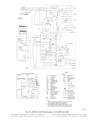
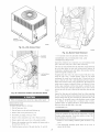
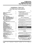
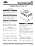
Fig. 1--Unit 48GS and 48GX
(Low NO× Model Available)
21
ADJUST-
..............................................................................
COOLING
A99338
REFRIGERANT
...........................................................................
INDOOR
MENTS
OPERATION
reserves
PC 101
the right
to discontinue,
Catalog No
534-80128
or change
and servicing
Form
of air-conditioning
due to system pressure
and qualified
air-conditioning
at any time, specifications
Printed in U.S.A
CONSIDERATIONS
or designs
48GS.GX-6SI
personnel
equipment
and ebctrical
should
install,
can be
components
repair,
Only
or service
equipment.
without
notice
Pg 1
and without
11-02
incurring oNigations.
Replaces:
48GS.GX-5SI
Untrained
personnel
can perfbrm
basic
maintenance
functions
of
cleaning coils and filters. All other operations should be perfbrmed
by tlained service personnel
When working
on air-conditioning
equipmenL
observe
attached
precautions
to the unit,
Follow
and other safety
all safe V codes.
quenching
cloth
available
nancQ
installation,
which
can
Consuh
supplier
for information
when
aheration,
monoxide
result
a qualified
service,
in personal
installer,
for shipping
If unit appears
have
or assistance.
or unit
agency,
The qualified
and amperage
agree with power
damage
it examined
claim
directly
for any damage
all items
against
distributor
if any item is missing.
shipping
installer
switch
could
and install
cause
Recognize
When
lockout
serious
safety
Understand
the signal
shock
the unit.
the tiffing
in the composite
symbolz_
or manuals,
a
be alert to
injory.
DANGER,
WARNING,
CAUTION,
and NOTE. These words are used with the safcV-alert
symboh
DANGER
identifies the most serious hazards which will result in
serious
injury
or death. WARNING
result in serious
unsafe practices
product
tions
a hazard
will
damage.
result
NOTE
is used
in enhanced
to highlight
installation,
length
bracket
existing
these
cover
national
minimuna
standards
instructions
and safety
exceed
certain
codes.
local
or
and confbrm
In some
codes
and
to
assembly
combination
Category-
ibr outdoor
installation
unit
sizes have return
and downflow
units
units designed
(See Fig. 2 and 3 for unit dimensions).
and discharge
configurations,
duct openings
a rooftop,
a cement
openings
ibr both horizontal
and are ii_ctory
covered.
All
shipped
with
all
Units may be installed
either
on
slab, or directly
on the ground
if local
codes
(See Fig. 4 for roof curb dimensions).
Models
with an N in the fifth position
dedicated
Low NOxunits
These
models
(NOx)
emissions
shipped
from
Quality
meet
requirements
the factory
Management
1--CHECK
IDENTIFY
The unit
designed
maximum
where
AND
nmnber
are
installations.
oxides
of 40 nanograms
and must
Districts
of the model
fbr California
the California
RECEBVING
Step
cooling
be installed
of nitrogen
joule
or less as
in California
Air
a Low NO× rule exists.
identification
plate. Check
and serial
nunfber
this information
are stamped
against
the base
of the
into the rigging
holds
buckle
around
bottom
(ratchet
type)
perimeter
tension
buckle
as shown
buckle
unit taut.
to lock strap in tension
squeeze
the tension
must be secure
safkty latch, Ilk lever,
buckle
until
in the rigging
6. Attach
field=supplied
7. Attach
clevis
bracket
buckle
of
in Fig 7A.
To release
and pull webbing
it is taut
Lifting
brackets
holds
shipping
or hook
brackets.
lifting brackets
8. Position
DO NOT
point directly
straps.
Lower
2--PROVIDE
ROOF
CLRB
Install
accessory
to the clevis or hook
attach
the safkty straps
over the unit's
When unit is directly
2 safety
strips,
to
at the
to the
UNiT
the
onto the roof curb.
SUPPORT
roof curb in accordance
roofing,
center of gravity.
over the roof curb, remove
the equipment
with instructions
with curb (See Fig. 4 for roof curb dimensions).
cant
strength
(See Fig. 7B).
liking
9. Lift unit.
of sufficient
(See Fig. 7B).
the 2 safkty straps directly
4 rigging
and flashing
Install
Ductwork
must
shipped
insulation,
be attached
to
curb
IMPORTANT:
The gasketing
for a watertight
seal. Install
roof curb. Improperly
of the unit to the roof curb is critical
gasketing
applied
material
gasketing
supplied
with the
can also result in air leaks
and poor unit perfbrmance.
Cm:b should
be level to within
drain to Nnction
instructions
SLAB
properly.
for additional
1/4 in. This is necessa_'
Refkr to accessory
information
for unit
roof curb installation
as required.
MOUNT
4 in. thick with 2 in. above
EQUIPMENT
number
around
tension
Place the unit on a solid,
INSTALLATION
UNIT
model
use a
not twist
throngh
Step
Fig. 1) are fu!ly self_containe&
I gas heating/electric
downflow
permit
(See
available,
through
Pull strapping
5. Tighten
instances,
INTRODUCTION
and 48GX
packages
unit t_-om damage.
c
strapping,
outward
ordinances,
especially those that may not have kept up with changing residential construction
practices.
We require these instructions
as a
minimum
ibr a saf_ installation.
The 48GS
the
sugges-
reliability,
requirements
skid is not
b. Feed strapping
hole in the liking
instructions
in original
to protect
strapping
of tension
d. Snap lever down
operation.
These
notify
pan.
Open lever
which could
inju V or death. CAUTION
is used to identii_,
which would result in minor personal injury or
and property
which
signifies
Manu-
in transit
Immediately
3. Place each of the 4 metal lifting brackets
power
or explosion
This is the safety-alert
words
incurred
all parts
If the wood
bar of sufficient
4. Thread liking bracket
unit as follows:
in instructions
removal
on mail
main
or death.
infbrmation
_br personal
operations
mrn off unit
tag. Elecn'ical
inju_
you see this symbol
the potential
Then
before
company
1. Remove unit from shipping carton Leave top shipping skid on
the unit as a spreader bar to prevent the rigging straps from
kits or accessories
or maintenance
pallet.
INSTALLATION
or gas
damaging
to unit.
list
leave
unit. Be sure the strap does
service
inspectors
to transportation
nearest
2. Position
peribrming
listed
to unit
is still on shipping
Check
this product
mrn off gas supply
provided
or is torn loose t'rom its anchorage,
by transportation
papers
is not responsible
spreader
Beibre
requirements
supply
while unit
to be damaged
To prevent loss or damage,
until installation.
fire, or
injury
service
plate
SHIPMENT
Forward
mainte-
poisoning,
must use only factory-authorized
modifying
Use
fire extinguisher
Inspect
facturer
adjustment,
damage.
or agency
Have
operations.
or use can cause carbon
an explosion
INSPECT
that may apply.
and work gloves.
operations.
on unit rating
tags, and labels
precautions
Wear safety glasses
for unbrazing
ibr all brazing
Improper
in the literature,
and job data. Verit}' unit voltage
level concrete
grade.
compressor
end of the unit (to allow
and should
extend
on unit
(See
Fig. 6). Do
papers
required
condensate
2 in. on the three
not
by local codes.
secure
the
pad that is a minimum
The slab should
unit
remaining
to the
of
be flush on the
&ain installation)
sides
slab
of the unit
e:vcept when
ZS4
86 I
(t
CD,[
[_H
[
GJ
I
""
[_9 K,] i[
_
j
_
5q }
_
5
:
[2, _o]
_
[o
oo] i
_1,
,
:
_C,_494_ 0_i t:¸
OPU 6
t'
i
N
249
550 5
IN _;i
;
i,, s1
?49 6
}9 8_]
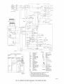
REAR ViEW
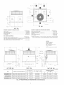
REQUIRED CLEARANCE TO COMBUSTIBLE
MATL
REQUIRED CLEARANCE
TOP OF UNIT ...................................................................................
DUCT SIDE OF UNIT .........................................................................
SIDE OPPOSITE
DUCTS ................................................................
BOTTOM OF UNIT .............................................................................
ELECTRIC
HEAT PANEL .................................................................
INCHES
14.00
200
14.00
050
3600
[mm]
[355 6]
[508]
[355 8]
[127]
[914 4]
FOR OPERATION AND SERVICING
INCHES [mm]
36.00 [914 0]
3600 [914 0]
EVAR COIL ACCESS SIDE ............................................................
POWER ENTRY SIDE ....................................................................
(EXCEPT FOR NEC REQUIREMENTS)
UNIT TOP .......................................................................................
SIDE OPPOSITE
DUCTS ..............................................................
DUCT PANEL .................................................................................
48.00 [1219 2]
36.00 [914 0]
1200 [304 8] *
NEC. REQUIRED CLEARANCES,
INCHES
BETWEEN UNITS, POWER ENTRY SIDE ....................................
42.00
UNIT AND UNGROUNDED
SURFACES.
POWER ENTRY SIDE 3800
UNIT AND BLOCK OR CONCRETE
WALLS AND OTHER
GROUNDED
SURFACES
POWER ENTRY SIDE .........................
4200
[mm]
[1086 8]
[914 0]
*MINIMUM
DISTANCES:
IF UNIT IS PLACED LESS THAN 1200 [304 8] FROM
WALL SYSTEM, THEN SYSTEM PERFORMANCE
MAYBE COMPROMISE
[1066 8]
LEGEND
CO Center of OravRy
COND Condensor
EVAP Evap@ator
NEC National E[ectnca[Code
REQ'D Reqused
NOTE: Dimensions are in in [mm]
COOO55
UNIT
ELECTRICAL
48GS018040
48GS024040/080
48GS030040/080
CHARACTERISTICS
UNIT WEIGHT
208/230-1-60
Ib
249.0
208/230-1-60
208/230-1-60,
208/230-3-60
T
CENTER
UNIT
HEIGHT
IN. ([VIM)
,,A,_
X
kg
113.2
35.02
(889.5)
20.0
(508.0)
280.0
127.3
35.02
(889.5)
22.5
280.0
127.3
35.02
(889.5)
21.5
OF
GRAVITY
IN.(MM)
Y
140
(3556)
(571.5)
130
(3302)
(546.1)
1375
(349.3)
Z
15.0(3810)
15.0(3810)
150 (3810)
48GS038060/090
208/230-1-60,
208/230-3-60,
460-3-60
320.0
145.1
37.02
(940.3)
22.5
(571.5)
140
(355.6)
130
(3302)
48GS042060/090
208/230-1-60,
208/230-3-60,
460-3-60
355.0
161.4
35.02
(889.5)
21.5
(546.1)
135
(342.9)
130
(3302)
290.0
131.5
37.02
(940.3)
22.0
(558.8)
145
(3683)
16.0
(4064)
313.0
142.0
39.02
(991.1)
22.0
(558.8)
153
(3874)
176
(4470)
321.0
145.6
35.02
(889.5)
22.0
(558.8)
153
(387.4)
165
(4191)
48GX624040/060
48GX036040/060
48GX036066/090
208/230-1-60
208/230-1-60,
208/230-1-60,
208/230-3-60
208/230-3-60,460-3-60
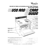
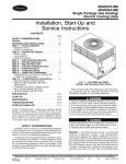
Fig. 2--48GS018-042
and 48GX024-036
Unit Dimensions
_3427
_
[!3 49]
3558
{1411]
3558
[14 Oi]
[33£1
SUPPLY
70
[2
4
77]
i
[16
4066
[1601]
O!]
402 o
[15 83]
i
E_AP
COIL
[1177
{a
C01L
631
i
88 3
[3 46]
[13831
[13 62]
TOP VIEW
[13831
REAR VIEW
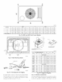
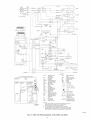
REQUIRED CLEARANCE TO COMBUSTIBLE MATE
REQUIRED
INCHES
14,00
2.00
14,00
0.50
36,00
TOP OF UNIT ...................................................................................
DUCT SIDE OF UNIT .........................................................................
SIDE OPPOSITE DUCTS ................................................................
BOTTOM OF UNIT .............................................................................
FLUE PANEL ....................................................................................
[mini
[355 6]
[50.8]
[355 6]
[12.7]
[914 4]
CLEARANCE
FOR OPERATION
AND
SERVICING
EVAR COIL ACCESS
SIDE ............................................................
POWER
ENTRY
SIDE ....................................................................
INCHES
3600
3600
[mm]
[914 0]
[914 0]
(EXCEPT
FOR NEC REQUIREMENTS)
UNIT TOP .......................................................................................
SIDE OPPOSITE
DUCTS
..............................................................
4800
3600
[1219.2]
[914 0]
DUCT
1200
[304
PANEL
.................................................................................
8]
NEC. REQUIRED CLEARANCES,
INCHES
BETWEEN UNITS, POWER ENTRY SIDE ....................................
4200
UNIT AND UNGROUNDED SURFACES, POWER ENTRY SIDE 3600
UNIT AND BLOCK OR CONCRETE WALLS AND OTHER
GROUNDED SURFACES, POWER ENTRY SIDE ......................... 4200
*MINIMUM DISTANCES: IF UNIT IS PLACED LESS THAN 1200 [304 8] FROM
WALL SYSTEM, THEN SYSTEM PERFORMANCE
MAYBE COMPROMISE.
[mm]
[1066.6]
[914.0]
[1066 8]
LEGEND
CG - Center of Gravity
COND - Condensor
EVAP- Evaporator
NEC - National Electrical Code
REQ'D - Required
k_-
1939
10906
[42 943
47
_'<
_
OO]
,
.......
"
NOTE:Dimensionsare in in, [ram]
4
,OO/
i?
i
"
\
MPRESSOR,
BLOtlER 6AS S{CTION
& Et CTR CAt £;¢[SS PANEl
...........
' ..............
[.8 1
i
[ 68]
329 O
L[4iR)
12 i [O 881 OlA I@lE
CONTROLEN/RY
.......................
A_
L._
!15
[4 54]
V I
i
o
FLUE FLOOD
fY _4]
528
7 [O 50] N P T
GAS ENTRY
5 O
It231
[44 22]
LEFT SIDEVIEW
UNiT
FRONTVIEW
ELECTRICAL
CHARACTERISTICS
UNIT
WEIGNT
RIGHTSIDE VIEW
000056
CENTER OF GRAVITY
IN.(MM}
UNIT HEIGHT IN. (MM)
"A"
X
Y
Z
16 (406.4)
17 (432 0)
Ib
kg
48G8048090/115/130
208-230/1/60,
208/230-3-60,
460-%60
415
1886
38.98
(990.2)
48GS0600901115/130
208/230-1-60,
208/230-%60,
460-3%0
450
2045
38.98
(990.2)
16 (406.4)
17 (4320)
48GX042060/090
208/230-1-60,
208/230-3-60,
460-3-60
382
1733
38.98
(990.2)
23.0
(584.2)
163 (412.8)
166 (4216)
48GX048090/115/190
208/230-1-60,
208/230-%60,
460-3-60
421
1910
(990.2)
21.5
(546.1)
166 (422.1)
180 (4572)
48GX060090f115/130
208/230-1-60,
208/230-%60,
460-3-60
468
2123
(1091.1)
23.5
(596.9)
163 (412.8)
176 (4470)
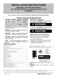
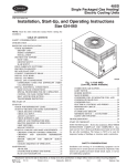
Fig. 3--48G8048-060
38.98
42.98
and 48GX042-060
22 (5585)
22 (5585)
Unit Dimensions
*
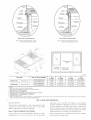
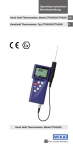
RoofCurb
for Small
Cabinet
Roof
Note A: When uNt mounting screw is used,
retah3er bracket must also be used.
Curb
for Large
Cabinet
Note A: When unit mounting screw is used,
retainer bracket must also be used.
R/A
S/A
/\
-'-_- Gasket around_
duct
\
\
insulated
deck pan
Suppolt
\
Gasket around
outer edge \
\,
Long
SL pport
iBXC}
C00076
UNiT S_ZE
48GS018o042
ODS CATALOG
48GX024-036
48GS048o060
48GX042-060
NUMBER
A
IN. {NM)
B
IN.(MM)
C
RN. (MM)
D
IN. (t_M)
2G3/4 (730)
CPRFCURB006A00
8 (203)
11(279)
161/2 (419)
CPRFCURB007A00
14 (356)
11(279)
161/2 (419)
28-3/4 (730)
CPRFCURB008A00
8 (203)
16 3/16 (411)
17 3/8 (441)
40-1/4 (1022)
CPRFCURB009A00
14 (356)
16 3/16 (411)
17 3/8 (441)
40-1/4 (1022)
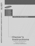
NOTES:
1. Roof curb must be set up for unit beh_ginstalled
2.
3.
4.
5.
6.
7.
8.
9.
Seal strip must be applied, as required, to unit being installed.
Dimensions in ( ) are in millimeters
Roof curb is made of 16-gage steel.
Table lists only the dimensions, per part number, that have changed
Attach ductwork to curb (flanges of duct rest on curb)
InsuIated panels: 1-in. thick fiberglass 1 Ib density.
Dimensions are in inches
When unit mounting screw is used (see Note A), a retainer bracket must be used as well This bracket must also be used when required by code for hurricane
seismic conditions. This bracket is available through Micrometl.
Fig. 4--Roof
-->
GROL ND MOL_T
ground
if local
prepared
Curb Dimensions
applications,
The unit may be installed
codes
with gravel
either
permit.
on a slab or placed
Place
_br condensate
the unit
directly
on level
on the
ground
discharge.
openings
unit
3--FIELD
Secure
discharge
all ducts
uriits
FABRICATI=
to roof
DUCTWORK
curb and building
Do t_nt connect
duct_oHc
tlansmission
ductwork
should
strecture
on vertical
Ducts
passing
and covered
ductwork,
flanges
joints,
and/or
barrier.
d_e horizontal
is recommended
noise
to stl_acture.
Insulate
and roof openings
with applicable
an unconditioned
a vapor
on
duct connector
to the flanges.
in accordance
through
with
of vibration
be secured
and mastic
with
of flexible
to prevent
flashing
to z_nit. For horizontal
is provided
Installation
proof all external
Step
or
space
All
and weather°
with counter
codes
must be insulated
Y
4
x
3
C00070
48GS
CORNER
TOTAL
48G×
#
018
024
030
036
1
47.3
53.2
53.2
59.7
2
44.8
50.4
50.4
56.5
639
3
77.2
86.8
86.8
97.3
1101
4
79.7
89.6
89.6
106.5
1136
WEIGHT
249
280
280
320
Fig. 8--48GS
042
675
355
048
060
024
030
036
042
048
060
789
85.5
55.1
595
61.0
72.6
800
88.9
747
81.0
52.2
563
57.8
68.8
758
84.2
128.7
1395
89.9
970
99.5
1184
130.5
145.1
132.8
1440
92.8
1002
102.7
1222
134.7
149.8
415
450
290
313
382
421
468
321
and 48GX Unit Corner We{ghts
DIJCTS
PLAOE
SEAL STRIP MI _ST BE _N
PLACE BEFORE PLACING
_JN_T ON RO©F CURB
BASEPAN
BEFORE
2 F_
SLOT
(BELOW
RIGGtNG
HOLDS}
RIGGING
(50.8mn
C99015
SRZE
EVAR
COIL
tb
COND.
COIL
J
Mounting
WE,GNT
[
A
kg
in.
[
B
mm
in.
mm
UNIT 48G8
C99014
Fig. 6--Slab
MAX,MUM
Details
HANDHOLD
/
0t8
271
123.2
20.0
508.0
14.0
355.6
024
302
137.3
22.5
571.5
13.0
330.2
030
302
137.8
21.5
546.1
13.75
349.3
036
342
155.1
22.5
571.5
14.0
355.6
042
377
171.4
21.5
546.1
13.5
342.9
048
437
198.6
22.0
558.5
17.0
432.0
050
472
214.5
22.0
558.5
17.0
432.0
UNIT 48GX
C99067
Fig. 7A--Threading
024
312
142
22.0
558.5
14.50
368.3
030
335
152
22.0
558.5
15.30
388.6
036
343
156
22.0
558.5
15.30
388.6
042
404
183
23.0
584.2
16.3
414.0
048
443
201
21.5
546.1
16.3
414.0
050
490
222
23.5
596.9
16.3
414.3
BoR for RiggBng
If a plemma return is used o,1 a vertical unit, the return should be
ducted through the roof'deck to comply with applicable i_re codex
A n_inimum clearance is not required around ductwork_ Cabinet
return=air static shall not exceed -25 in. wg.
Fig. 7B--Suggested
Step
4--PROVIDE
Rigging
CLEARANCES
The required minimum operating and service clearances are shm_n
in Fig 2 and 3 Adequate combustion, ventilation and condmlser
air must be provided in accordance with section 53, Air fbr
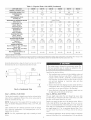
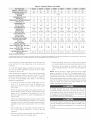
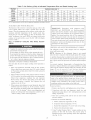
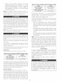
Table 1--Physical
UNIT SBZE 48GS
NOMINAL
Data--UnR
48GS
024040
024060
030040
030080
036060
038080
042060
1½
2
2
2½
2½
3
3
3½
3½
249
280
280
280
280
320
320
355
355
018040
CAPACBTY (ton)
OPERATING WEIGHT
COMPRESSORS
Quantity
(_b.)
042090
Reciprocating
1
REFRmGERANT (R-22)
Quantity (_b.)
REFRIGERANT
METERING
Orifice
AcutroF M Device
DEVICE
.034
ID (in.)
I
.O34
.034
.034
.034
.032
.032
.034
.034
1...17
9.1
1._17
9.1
1_17
9.1
1...17
9.1
1...17
10.9
1._17
10.9
1_.17
9.1
1._17
9.1
2400
22
2400
22
2400
22
2400
22
3000
22
3000
22
3000
22
3000
22
1/8 (825)
1/8 (825)
1/8 (825)
¼ (1100)
¼ (1100)
¼(1100)
2...I5
3.1
2...15
3.1
2...15
3.1
3...15
3.1
3...15
3.1
4...15
3.1
4...15
3.1
800
10x10
1/4 (I075)
1000
10x10
1/4 (1075)
1000
10 x 10
lg (1075)
1200
11 x 10
1/2 (I075)
1200
11x10
1/2 (1075)
1400
11x10
3/4 (1075)
1400
11x10
3/4 (1075)
2...45
2...50
2...38
2...46
2...45
2...50
2...38
2...46
2...38
2...46
3...38
3...46
2...38
2...46
3...38
3...46
20x20
20X20
20 X 20
20 X 24
u
CONDENSER CORL
Rows...Finslin.
Face Area (sq ft)
CONDENSER FAN
NominN Cfm
Diameter (in.)
Motor Hp (Rpm)
EVAPORATOR COBL
Rows...Fins/in.
1
[
n
u
2000 1
1/8 (825) 1 1/8 (825)
¼ (1100)
u
2...15
" __
.J
Face Area (sq ft)
EVAPORATOR BLOWER
I
',
2...15
3.1
u
600
I
8OO
10x10
I 10 x 10
1/4 (87511 1/4 (1075)
Nomina_ Airflow (Cfm)
Size ({n.)
Notor BP (Rpm}
FURNACE SECTION*
u
Burner Orifice No. (Qty...Drill
Natural Gas
Size)
Burner Orifice No. (Qty...Drilt
Propane Gas
Size)
RETURN-ABR FILTERS
Throwaway
17
6 I
2...45
2...50
I
I
u
(in.)?
20x20
I
20x20
20X24
20x24
20x24
* Based on altitude of 0 to 2000 ft
? Required filter sizes shown are based on the larger of the ARI (Air Conditioning and Refrigeration Institute) rated cooling airflow or the heating airflow velocity of 300
fi/minute for throwaway type or 450 if/minute for high-capacity type. Air filter pressure drop for non-standard filters must not exceed 0.08 in. wg
(ombustion
and Ventilation,
(American
National
of the National
Standards
provisions
of local building
7.3, or 7.4 or CaniCGA.
Installation
Codes
condenser
provisions
airflow.
condenser
£m
pulls
air through
discharges it through the top cover
does not recirculate to the condenser
either
a comer
clearance
or under
under
overhang)
is 48-im
extension
of a partial
Do not place
or roof will
carpeting,
damage
or flood
tile, or other
5--RIG
AND
(such
condenser
coil
as a nomml
ice, or snow
riggi<g
to
and
materials.
a_d mo_,i_tg operaff(ms.The
condensate
accessory
roof
level
and
Step
support
Use
the additional
spreader
must be rigged
bars
house
horizontal
flora an overhang
The
the unit on
unit nmy be
A, B, or ( roof
covering
g--CONNECT
When
Models
48GS
on a rooftop,
top when
(See Fig
be sure the roof will
rigging
6). Refer
unit.
fitting
setting
14"
pad or
the unit in place.
Lifting
point
should
is
be
for the unit.
DRAIN
condensate
&ain
connection
be sure to
and restrictions.
and 48GX
in. NPT
the
CONDENSATE
with local codes
3/4
the ground°level
is used, be sure that the support
of gravity
installing
dispose
which
exits
of condensate
through
water
through
the compressor
a
access
panel (See Fig. 2 and 3 for location).
Condensate
water
installations
can be drained
(where
level installations.
permitted)
Install
the uniL The units
to Table
1 and 2 for
directly
onto the roof
or onto a gravel
a field°supplied
condensate
in ground-
trap at end of
connection
to ensure
the outlet
of the trap
is at least
1 in. lower
condensate
connection
to prevent
the pan fl'om overflowing
Fig
8)
Prime
make sure
the
trap with
it slopes
installation
away
proper
trap
water
draining
than
using
1 in. lower
This prevents
than
the pan tiom
Connect
of 3/4-in.
copper
or 3/4-in.
sure that
the drain
a gravel
the condensate
(See Fig. 8). Make
Prime the trap with water.
outlet
When
Make
a 2=ira trap at the condensate
&ainage
PVC
drainage
pan
(See
apron,
fl'om the unit
requires
is at least
proper
in rooftop
apron
condensate
from the unit, install
UNW
_eight
or crate
for lifting
supports
over the center
connection.
the unit
support
comply
the
installing
properly
whe_
dHring a//
unit must be level within
therefore,
curb must be level before
a field°fi_bricated
ensure
When
drainage;
When
If the
PLACE
L'xe e:v::'eme ca_ltio_v to prea,e_vt damage
for proper
directly
48-in_
Do not install
or on (;lass
weight.
mu_ ing the _mit. Unit m_¢stremain in an upH@tpo,sition
The minin-mm
top. The nmximnm
the unit.
operating
NOTE:
obstruction.
combustible
flooring
code.
at either
can be detrimental
must not exceed
the unit where water,
installed on wood
materials.
Step
the unit
overhang
_bllow sections 7.2,
Association)
B149
of local building
the
overhang
above
applicable
Be sure that the fan discharge
coil Do not locate the unit in
an overhead
a pmlial
or
An air restriction
the outdoor-air
inlet or the £m discharge
compressor
tiff.
The
Z2231
code In Canada,
(Canadian
Gas
or applicable
Do not restrict
Fuel Gas <ode ANSI
Institute)
end of the 2=ira trap.
water
away
connection
sure that the outlet
the
drainpan
to
of
condensate
overflowing.
a &ain tube
using a mininmna
pipe (all field=supplied)
Do not undersize
at the
the robe. Pitch the
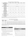
Table 1--Physical
UNiT SIZE 48GS
NOMINAL
CAPACITY
OPERATING WEIGHT
COMPRESSORS
Quantity
048130
(ton)
4
4
4
5
5
5
(lb.)
415
415
415
450
450
450
0$0090
060 t 18
Scroll
1
METERING
Orifice
48GS (Continued)
048115
REFRIGERANT {R=22)
Quantity (lb.)
REFRIGERANT
Data--Unit
048090
Reciprocating
1
8.0
8.0
8.0
6.0
6.0
6.0
.032
.032
.032
.030
.030
.030
1._17
12.3
1._17
12.3
1...17
12.3
2...17
12.3
2._17
12.3
2._17
12.3
3600
22
3600
22
3600
22
3600
22
3600
22
3600
22
'/_ (1100)
1/_(1100)
1/_(1100)
'/_ (1100)
'/_ (1100)
'/_ (1100)
3...15
4.7
3...15
4.7
3...15
4.7
4._15
4.7
4._15
4.7
4...15
4.7
1600
11X10
3/4 (1075)
1600
11X 10
3/4 (1075)
1600
11 X 10
3/4 (1075)
2000
11 X 10
1.0 (I075)
2000
11X10
1.0 (1075)
2000
11X10
1.0 (1075)
3._38
3...46
3...33
3...42
3...31
3...41
3...38
3...46
3_.33
3...42
3_.31
3...41
24 X 30
24 X 30
24 X 30
24 X 30
24 X 30
24 X 30
Acutrol Device
DEVICE
ID (in.)
CONDENSER COIL
Rows...Fins/im
Face Area {sq ft)
CONDENSER FAN
Nominal Cfm
Diameter (in.)
Motor Hp (Rpm)
EVAPORATOR COIL
Rows...Finsiim
Face Area (sq ft)
EVAPORATOR BLOWER
Nominal Airflow (Cfm)
Size (in.)
Motor Bp (Rpm)
FURNACE SECTION*
Burner
Orifice No. {Qty...DrSI
Natural Gas
Size)
Burner
Orifice No. {Qty...DrSI
Propane Gas
Size)
060130
RETURN-AIR FILTERS {in.)?
Throwaway
* Based on altitude of 0 to 2000 ft
1 Reqaired filter sizes shown are based on the larger of the AR[ (Air Conditioning and Refrigeration Institute) rated cooling airflow or the heating airflow velocity of 300
ft/minate for throwaway type or 450 if/minute for high-capacity type. Air filter pressure drop for non-standard filters must not exceed 0.08 in wg
drain robe downward
at a slope of at least 1-in. %r every
horizontal
run, Be sure to check the drain robe for leaks,
1
10 ft of
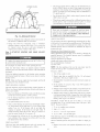
The venting
system
is designed
TRAP
OUTLET
Install
1" min.
the flue hood
Association)
cial
plumbing
and
local
C00009
Fig. 8--Condensate
screw
Trap
The flue hood
assembly
indoor
blower
locate
the assembly
models
emissions
screwed
Remove
to the coil panel in the
the service
access
panel
to
low NO x models
Management
meet
shipped
from the fhctory,
NOTE:
lations,
Low NO x requirements
MUST
Districts
the California
requirements
)"he
in vent cap with
flue hood
be installed
where
maximmn
in Call=
a Low NO× rote
oxides
of 40 nanogramsdoule
of nitrogen
or less as
wastewater
Refer
(National
to Provin=
codes
and
other
provided,
a single
screw
on
side and the tet_ side of the hood.
8--INSTALL
gas
holes in the flue panel
to flue panel by inserting
supply
GAS
pipe
PIPING
enters
The gas connection
gas inlet on the manual
(See Fig. 3i).
Dedicated
(NOx)
is shipped
compartment
fomia Air Quality
exists,
These
Step
HOOD
or
revision
local codes,
holes
the right
FLUE
latest
2, Remove flue hood from shipping location (inside the blower
compartment)
Place vent cap assembly over flue panel, Orient
3, Secure
7--INSTALL
codes and
Z223 1 (in
B 149,1, and B 149 2) or NFPA
Fire Protection
applicable
The
in this
as fbllows:
( anada., CANiCGA
NOTE:
venting.
1, This installation
must confot_n with local building
with the National Fuel Gas (?ode (NFGC), ANSI
2" rain.
Step
to ensure proper
flue hood assembly
must be installed
as indicated
section of the unit installation
insm/ctions,
the
unit
through
the
access
hole
to the unit is made to the 1/2=in, FPT
shutoff
or gas valve.
Install a gas supply line that runs to the heating section. Refer to
Table 3 and the NFGC for gas pipe sizing. Do _ot zlse cast-iros_
pipe.
It is recommended
local
utility
gas supply
_¢se pipe
that a black
for recommendations
piping
smaHe/'
iron pipe is used.
concerning
for 0,5 in, wg maximum
than
existing
pressure
Check
lines.
drop,
the
Size
_\2_*er
the ].lL_:in+ FflY gax m/et up tile zmit ,?aX
ICt]1'C.
apply
only to natural
gas instal-
For natural
gas applications,
the gas pressure
must not be less than 4.0 in. wg or greater
at unit gas connection
than 13 in. wg while the
TaNe 2--Physicam Data--Unit
UNiT BBZE 48GX
NOMINAL
024040
CAPACITY
2
2
2"½
2_½
290
290
313
313
030060
036090
042060
042090
3
3
3½
3½
321
321
382
382
Scroll
1
Orifice ID (in.}
CONDENSER COBL
Rows...Fins/in.
Face Area (sq ft}
CONDENSER FAN
Nominal Cfm
Diameter (in.)
Motor Bp (Rpm)
3.7
3.7
4.4
4.4
5.2
5.2
6.4
6.4
.034
.034
.030
.030
.032
.032
.034
.034
1._17
10.8
1._17
10.8
1_.17
12.7
1...17
12.7
2...I7
9.1
2...17
9.1
2...17
12.3
2._17
12.3
2350
22
2350
22
2350
22
2350
22
2350
22
2350
22
3300
22
3300
22
1/8 (825)
1/8 (825)
1/8 (825)
1/8 (825)
1/8 (825)
1/8 (825)
1/8 (825)
1/8 (825)
3...15
3.1
3_.15
3.1
3._15
3.1
3._15
3.1
3._15
3.7
3...15
3.7
3_.15
4.7
3_.15
4.7
800
10X10
800
10X10
1000
10X10
1000
10X10
1200
11X10
1200
11X10
1400
11X10
1400
11X10
EVAPORATOR COIL
Rows...Fins/in.
Face Area (sq ft}
EVAPORATOR BLOWER
Nominal Airflow (Cfm)
Size (in.)
Motor Hp {Rpm)
1/4 (1075)
1/4 (1075)
1/4 (1075)
1/4 (1075)
1/2 (1075)
1/2 (1075)
3/4 (1075)
3/4 (1075)
2...44
2_.38
2_.44
2...38
2...38
3...38
2...38
3_.38
2...50
2...46
2...50
2...46
2...46
3...46
2...46
3...46
20 X 20
20 X 20
20 X 20
20 X 20
20 X 24
20 X 24
24 X 30
24 X 30
SECTION*
Orifice No. (Qty...DriH Size)
NaturN Gas
Burner
48GX
030000
(lb.)
REFRmGERANT (R-22)
Quantity (_b.)
RBFRBGERANT METERBNG DEVICE
Burner
030040
(ton)
OPERATING WEIGHT
COMPRESSORS
Quantity
FURNACE
024000
Orifice No. (Qty...DriH Size)
Propane Gas
R_:TURN-ABR FBLTERS (Jn.)t
Throwaway
* Based on altitude of Oto 2000 ft
? Required filter sizes shown are based on the larger of the ARI (Air Conditioning and Refrigeration Institute) rated cooling airflow or the heating airflow velocity of 300
if/minute for high-capacity type Air filter pressure drop for non-standard fitters must not exceed 008 in wg.
unit
is operating.
For propane
applications,
not be less than 7.0 in wg oi" greater
connection
An 1/8-in. NPT plugged
tiom
must
tapping,
be installed
connection
latest
absence
pertinent
fbr test gage conneco
upstream
of the gas supply
of
line, obsel_'e
Ref)r
(ANiCGA
building
codes,
ANSI
Z223J-1988
B 14% 1, (2)-M86).
adhere
to the
In
15
ft to
prevent
downward to risers.
and to meter.
2. Protect
traps.
Use risers
all segments
of piping
thermal
damage.
Support
hangers,
etc. Use
a mininmm
pipe sizes larger
national codes.
3. Apply joint
threads
d_an
compound
specified
by local
Grade all pipe 1/4 in. in
Grade
all
to connect
system
all piping
against
with
fbltow
(pipe dope)
physical
appropriate
and
straps,
eve N- 6 ft. For
sparingly
piping
by closing
slightly
opening
sediment
&ip
an accessible,
gas supply
pipe within
leg
Nnctions
:\;ever
external,
to heating
as
manual
6 ff of heating
is in excess
of 0.5 psig.
Pressure
must be isolated
main
the ground-joint
be
of the piping
section
external
must
the testing
at pressures
the
piping
to
test
equal to or less than 0.5
fi'om the gas piping
manual
shutoff
valve
and
union.
of
Unstable
manifbld
operation
assembly
may
ing improperlyorouted
a baclcup wrench
or distortion
occur
are forced
when
the
out of position
rigid gas piping
when making
of, the gas contIol
gas
valve
while
to the gas valve.
connection
and
connectUse
to avoid stlain on,
piping.
Use only pipe
petroleum
codes.
trap in riser leading
during
system
gases as
zz.se 7;e_7ot_
If a flexible
having
conductor
jurisdictiom
is required
black
gas valve and shall extend
Fig. 9). This
condensate.
5. Install
qfter the gas supply
The supply
piping
and only to male
pipe connections.
national
runs
tope.
4. Install
system
to the gas valve.
test pressure
system
and
test the gas supply
f?om the gas valve
when
local
connecting
section
recommendations
to action of liquefied
and/or
horizontal
to heating
of one hanger
1/2 in.,
of joint when making
dope that is resistant
systems
witla
before
psig. The unit heating
low spots in long runs of pipe.
ever?"
Pressure
in accordance
and gas codes
is connected
the gas supply
fbltowing
union close to heating section between
and external manual main shut-off valve.
all gas piping
plumbing
disconnected
recommendations:
1. Avoid
national
unit,
piping
local codes pertaining
to the NFGC
(in Canada,
local
Pressure-test
NOTI:::
the gas supply
edition
6. Install groundojoint
unit manual shutoff
?
accessible
immediately
to gas pipe installations.
the
must
to the gas valve.
When installing
NFPA
the gas pressure
than 13 in wg at the unit
a trap
main
section.
section
fbr
shutoff
(See
dirt
valve
and
in
casing.
or allowed
iron pipe shall
a nlinirnurn
by the authority
be installed
of 2 in. outside
at the
the unit
Table 2--Physical
UNiT BBZE 48G×
NOMINAL
Data--Unit
048090
CAPACBTY (ton)
OPERATING WEIGHT
COMPRESSORS
Quantity
(_b.)
48GX (Continued)
048115
048130
0g0090
060115
060130
4
4
4
5
5
5
421
421
421
468
468
468
Scrolt
1
REFRmGERANT {R=22}
REFRIGERANT
METERING
Orifice
OEVICE
Acutrol Device
ID (in.)
CONDENSER CORL
Rows...Finstin.
Face Area {sq ft}
CONDENSER FAN
Nominal Cfm
Diameter (in.)
Motor Hp (Rpm)
.034
.034
.034
.032
.032
.032
2...17
12.3
2._17
12.3
2._17
12.3
2...17
16.4
2_.17
16.4
2._17
16.4
3300
22
3300
22
3300
22
3300
22
3300
22
3300
22
_A(1100)
_¼(1100)
_¼(1100)
_A(1100)
_A (1100)
_A(1100)
4...15
4.7
4...15
4.7
4...15
4.7
4...15
4.7
4...15
4.7
4...15
4.7
1600
11 X 10
3/4 (1075)
1600
11 X 10
3/4 (1075)
1600
11 X 10
3/4 (1075)
1750
11 X 10
1.0 (I075)
1750
11 X 10
1.0 (1075)
1750
11 X 10
1.0 (1075)
3._38
3...46
3...33
3...42
3...31
3...41
3...38
3...46
3_.33
3...42
3_.31
3...41
24 X 30
24 X 30
24 X 30
24 X 30
24 X 30
24 X 30
EVAPORATOR COIL
Rows...Finslin.
Face Area {sq ft}
EVAPORATOR BLOWER
Nomina_ Airflow (Cfm}
Size ({n.}
Motor Bp (Rpm)
FURNACE SECTION*
Burner
Orifice No. (Qty...DriH
Natural Gas
Size)
Burner
Orifice No. (Qty...Drill
Propane Gas
Size)
RETURN-AIR FILTERS (in.)'(
Throwaway
Based on altitude of 0 to 2000 ft
1 Required filter sizes shown are based on the larger of the ARI (Air Conditioning and Refrigeration Institute) rated cooling airflow or the heating airflow velodty of 300
ft/minute for high-capacity type Air filter pressure drop for non-standard filters must not exceed 008 in. wg.
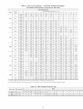
Table 3--Maximum
NOMINAL
IRON PIPE,
SIZE
(IN.}
V2
iNTERNAL
DIAMETER
(BN.}
10
20
Gas Flow Capacity*
LENGTH OF PIPE, FT¢
30
40
50
60
70
80
90
100
125
150
175
200
.622
175
120
97
82
73
66
61
57
53
50
44
40
--
--
%
.624
360
250
200
170
151
138
125
118
110
103
93
84
77
72
1
1.049
660
465
375
320
285
260
240
220
205
195
175
160
145
135
11/4
1.380
1400
950
770
600
580
530
490
460
430
400
360
325
300
280
1.610
2100
1460
1180
990
900
810
750
690
650
620
550
500
460
430
Capacity of pipe in cu ft of gas per hr for gas pressure of 0.5 psig or less. Pressure drop of 05-in
Fire Protection Association NFPA 54.
1 This length includes an ordinary
number of fittings
l
Never
use a match or other open flame when checking
leaks. Never
to follow
serious
purge
gas line into combustion
this warning
injury
wg (based on a 0.60 specific gravity gas). Refer to Tabte C-4, National
could
result
charuber.
in an explosion
CONFIGURING
( HARGE
%r gas
causing
Be%re
or death.
%r gas leaks at the field-installed
gas lines
Use
codes
after
all piping
soap-and-water
and/or
connections
solution
and factow-installed
have
(or method
been
specified
per%rming
cause
service
mrn off main
serious
injury
or maintenance
power
operations
to unit. Electrical
on the
shock
could
or death.
completed
by
1. Open
local
all electrical
disconnects
be%re
starting
any service
work_
regulations)
2. Remove
Step g--INSTALL
DIS-
Failure
system,
8. Check
UNITS FOR DOV_q',rFLOW (VERTI(AL)
DUCT CONNECTmONS
return
connecting
duct cover located
tabs with screw&iver
on duct panel
and a hammer
by breaking
(See Fig. 10A
& 10B).
The unit has duct flanges on the supply- and return-air openings on
the side and bottom o_["the unit, For downshot applications, the
ductwork connects to the roof cm'b (See Fig 2 and 3 for
connections sizes and locations)
3. To remove
connecting
down
10
supply
duct
cover,
tabs with a screwdriver
to break
break
flout
and right
and a hammer.
rear and left side tabs (See Fig.
side
Push touver
10A & 10B)
IN
--:u
TEE
OUT
_.._
I
NIPPLE
3"MIN
__!_1
CAP
C99020
Fig. 9--Sediment
Trap
DUCT
COVERS
REMOVED
C99012
Fig. lOB--Vertical
Adhere to the following
installing the duct system:
Duct
Cover
criteria when
Removed
selecting,
sizing_ and
1 Lnits are shipped for horizontal duct installation (by removing
&ct covers)
o
2 Select and size ductwork, supply-air registers, and return-air
grilles according to American Society of Heating, Refiigeration and Air (onditioning Engineers (ASHRAE) recommen=
dations
3 Lse flexible transition between rigid dnctwork and unit to
prevent transmission of" vibration. The transition may be
screwed or bolted to duct ['langes. Lse suitable gaskets to
ensure weathertight and airtight seal.
o
/
4
/
RETURN
DUCT
OPENING
SUPPLY
DUCT
OPENING
5. Size all dnctwork for naaximnm required airflow (either
heating or cooling) for unit being installed. Avoid abrupt duct
size increases or decreases or perfimnance may be affected.
C99011
Fig. 10A SupNy
4. If unit duct_xork
and Return Duct Opening
is to be attached
on the unit composite
at this time,
Collect
ALL screws
on rooftop
base (jackstand
5. It is recommended
damage
of the vertical
unit
with
require
aluminum
the
accessory
tape.
duct
opening
exposed
duct openings
cover
insulation
Applicable
tape to prevent
6. Cover both horizontal
only), do so
Do not lea_e
base
return°air
aluminum
6. Adequately insulate and weatherproof all ductwork located
outdoors. Insulate ducts passing through unconditioned space,
and use vapor barrier in accordance with latest issue of Sheet
Metal and Air Conditioning Contractors National Association
(SMA(NA)
and Air Conditioning Contractors of America
(AC(A) mininmm installation standards for heating and air
conditioning systems. Secure all dtlcts to building structure.
flanges
screws
to the roof may occur
that the unit
perimeter
opening
applications
that v, ere removed.
as pem_anent
base
to x ertical
kit.
around
be secured
local
may
fiberglass
with the duct covers
Ensure
7. Flash, weatherproof, and vibration-isolate
all openings in
building structure in accordance with local codes and good
building practices.
the
to the
codes
opening
fl'om
is air-
and
watertight.
7. After
completing
and power
unit
conversion,
perform
all safety
checks
up unit.
NOTE:
The design and installation
of the duct system must be in
accordance
with the standards
of the NFPA fbr installation
of
nonresidence-type
air conditioning
90A or residence-type,
ordinances.
NFPA
and ventilating
90B;
and/or
systems,
local
codes
All units must have field-supplied filters or accessory filter
rack installed in the return-air side of the unit. Recommended
sizes fbr filters are shown in Tables 1 and 2.
NFPA
and
11
Table 4--Electrical
UNIT
SBZE
48GS
VOLTAGE
RANGE
V-PH-HZ
Data--Unit
COMPRESSOR
Min
Max
48GS
OUTDOOR FAN
MOTOR
INDOOR FAN
MOTOR
FLA
MCA
Max Fuse or
Ckt Bkr
RLA
LRA
FLA
POWER SUPPLY
018
208/230-1-60
187
253
9.0
45.0
0.8
1.8
13.9
20
824
208/230-1-60
187
253
12.8
61.0
0.8
2.0
18.8
30
208/230-1-60
187
253
14.4
73.0
0.8
2.0
20.8
30
208/230-3-60
187
253
12.6
68.0
0.8
2.0
13.2
20
208/230-1-60
187
253
13.0
81.0
1.6
3.6
24.0
35
208/230-3-60
187
253
9.0
78.0
1.6
3.6
16.5
25
460-3-60
414
506
4.5
40.0
0.9
1.9
8.4
15
208/230-1-60
187
253
18.6
105.0
1.6
3.8
27.5
45
208/230-3-60
187
253
10.7
85.0
1.6
3.8
18.8
25
460-3-60
414
506
5.3
42.0
0.9
2.0
9.5
15
208/230-1-60
197
253
25.3
131.0
1.6
3.8
37.0
60
208/230-3-60
187
253
13.5
108.0
1.6
3.8
22.3
35
460-3-60
414
506
6.7
47.5
0.9
2.0
11.3
15
208/230-1-60
187
253
28.9
147.0
1.6
6.2
43.9
60
208/230-3-60
187
253
18.6
125.0
1.6
6.2
31.1
45
460-3-60
414
506
8.5
66.5
0.9
3.2
14.7
20
O3O
836
042
048
OGO
Step
10--INSTALL
ELECTRICAL
CONNECTIONS
The field-supplied
disconnect
unit over the high-voltage
tow-voltage
The
unit
electrical
must
cabinet
ground
if an electrical
an electrical
have
to minimize
fimlt should
wire
an
unimetTupted,
the possibility
occur.
connected
This ground
to the unit
control
compartment,
or
ground
when
in accordance
Electlical
trical
CSA
installed
Code)
codes.
ANSIiNFPA
In Canada,
(Canadian
electrical
approved
fi_llow
Failure
lug in the
voltage
connections
(22.1
elecCode
and
to this warning
Proceed
as follows
HIGH VOLTAGE
/
POWER
to %tlow
ANSINFPA
these precautions
.<_o_
LEADS
local
LABEL)
_
Canadian
(latest
Electrical
4Z::S
JsuPPLY
FIELD-SUPPLED
FUSED
DISCONNECT
only
copper
local
range
indicated
any panel
to mount
LOW-VOLTAGE
POWER
LEADS_
O
_
O
(SEE UNIT
WIRING
LABEL)
local
connections
switch
units,
Consult
local power
ensure phases
company
voltage
an&or
imbalance
(TYPICAL)
SPLICE
C99018
Fig. 11--High=
plate
Single
are balanced
through
conduit,
within
fbr correction
BOX
DO
operating
when drilling
hardware,
3-phase
between
and unit.
to unit is within
components
REDIRZ_> @
BRN!_ O" C)
fbr
power
THERMOSTAT
YELLYL_ Q)
codes
applicable
@
VV_TLV_)_
NEC
diagram.
electrical
phase
with
electrical
1 and
on unit rating
internal
CONTROLBOX
all electrical
connecCSA standard
C22.1
disconnect
WIRE
3 Be sure that high-voltage
4 Do not damage
Part
conductor
field-supplied
electrical
NOT USE ALUMINUM
to
'O"
and
(?ode
in damage
in accordance
edition)
RefBr to unit wiring
voltage
POWER
_:_
could result
could result
governing
such wiring
In Canada,
tions must be in accordance
with
Use
high
high-
injm?- or death.
the unit being installed:
1 Make all electrical connections
2
the
(SEE UNITWIRING_
GND
codes
when making
to complete
to the unit.
mm
Failure
and
(See Fig. 2 and 3 fbr acceptable
(National
Electrical
Association)
on the
power
electrical
and local
Canadian
to adhere
of
connections.
NEC
edition)
are used
label and Fig. 11 fbr refhrence
voltage
for
with
(latest
Standards
codes.
in serious
conduit
See unit wiring
injury
may consist
ground
box may be mounted
location).
unbroken
of serious
entIy points
switch
inlet hole when the standard
phase
and Control=Voltage
units:
1. Run the high-voltage
control box.
etc. On
2 percenL
of improper
Connections
(LI_
L2)
lead to chassis
and
ground
ground
leads
into
the
2. Connect
ground
connection.
3. Connect
L! to pressure
tug connection
11 of the compressor
4. Connect L2 to pressure
contactor.
tug connection
23 of the compressor
contactor,
HIGH-VOLTAGE
The
unit
supplied,
sight
must
CONNECTIONS
have
a separate
waterproof,
fi'om, the unit
disconnect
Refer
Nseicircuit
breaker
wire
(See Tables
sizing
electrical
switch
service
mounted
to the unit rating
size and minimum
circuit
4 and 5 for electrical
with
a field-
at, or within
plate
fbr maximum
amps
(ampacity)
Three-phase
for
units:
1. Run the high-voltage
control box.
data).
12
(L!,
L2, L3) and ground
leads
into the
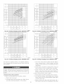
EXAMPLE: Suppty voltage is 460-3-60.
A B C
AB = 452 v
LEGEND
AC = 455 v
FLA
-- Full Load Amps
LRA
-- Locked Rotor Amps
MCA
-- Minimum Circuit Amps
MOCP -- Maximum Overcurrent Protection
RLA
-- Rated Load Amps
CKT BKR -- Circuit Breaker
Average Voltage = 452 + 464 + 455
3
BC = 464 v
_ 1371
3
= 457
NOTES:
Determine maximum deviation from average 'voltage.
(AB) 457 452=5v
(BC) 464 457=7v
(AC) 457 455=2v
Maximum deviation is 7 v.
1. tn compliance with NEC (National Electrical Code) requirements
for muttimotor and combination load equipment (refer to NEC
Articles 430 and 440), the overcurrent protective device for the
unit shall be Power Supply fuse. Canadian units may be
fuse or circuit breaker.
2. Minimum wire size is based on 60 C copper wire. If other than
60 C wire is used, or if length exceeds wire length in table,
determine size from NEC.
3. Unbalanced
3-Phase Supply 'Voltage
Never operate a motor where a phase imbalance in supply voltage is greater than 2%. Use the following formula to determine
the percentage of 'voltage imbalance.
Determine
percent of voltage imbalance.
7
% Voltage Imbalance = 100 x -457
: 1.53%
This amount of phase imbalance
maximum allowable 2%.
% Voltage imbalance
= 100 x
max voltage deviation from average voltage
average voltage
is satisfactory
as it is below the
IMPORTANT:
tf the supply 'voltage phase imbalance
is
more than 2%, contact your local electric utility company
immediately.
c99024
Table4_Legend
2. Connect
ground
lead to chassis
ground
connection
3. Locate the black and yellow
of the contactor
wires connected
4. Connect
wire
field
compressor
5. (onnect
L1
to black
SPE(IAL
on connection
wire on connection
wire L3 to Blue wire
PRO(EDURES
FOR
flora compressor
208-V
OPERATION
changes,
off first. Thet_ switch
make
off the power
Do not
VOLTAGE
TIONS
Unit
control
may result.
no.
18 American
Wire
Gage
(AWG)
color-coded,
insulated
(35 C minimum)
wires
between
the thermostat
to make the control voltage connections
and the unit. If the thermostat
is located
more
the unit
than
voltage
100 ft flora
wires),
minimmn)
no.
(as measured
16 AWG
knockout
access
hole located
panel
(See
in the flue panel
Fig.
2 and
grommet
fi'om the installer's
packet
grommet
in the knockout
opening.
wire through
Rtm the low-voltage
leads
five 18-gage
connection
brown,
(35 C
adjacent
to the
(included
Remove
the rubber
with unit) and install
Provide
fiom the thermostat,
splice
wires leaving
leads can be identified
and white
to be routed
3).
a drip
loop
before
panel.
hole, and into unit tow-voltage
Locate
fl_e control
insulated
( onnection
Remove
running
along
color-coded,
wires.
Standard
control
use
the inlet
box.
control
box. These
low-voltage
by the colors red, green, yellow,
(See Fig. 1 i). Ensure
into the low-voltage
through
the leads are long enough
splice box (located
below
Fig
11)
all
of unit.
SETTING
heat anticipator
required
setting.
NOT_::
For thermostat
selection
required
adjustment
setting.
must be properly
purposes,
Failure
will result
right
13
a greater
TRANSFORMER
PROTE(
The
is
tra_,_former
withstand
thermostat
thermostat
slightly to provide
installation.
st_pply to the
shock can cause serious
use any type of power-stealing
problems
Use
CONNE(
of control
Secure
adjusted
to
a 30-sec.
of
in improper
degree
a proper
operation,
heat
discom-
space, and inefficient
setting may be changed
of comfort
for a particular
TION
fl_e energy-limiting
overload
use 0.18 amp for fl-le
to make
fort to the occupants
of the conditioned
energy utilization;
however,
the required
sure the gas supply
or death.
CONTROL
ANTICIPATOR
anticipator
N
any wiring
hole in bottom
(See
so that _hey do not interI:_re with operation
approximate
iiiiiiiiiii_,
unit and install tockot_t tag. Electrical
injury
connections
ensure proper heating performance.
Set the heat anticipator,
using
an ammeter between the W and R terminals to determine the exact
13 of the
iii_
is switched
leads through
tow-voltage
HEAT
11 of the
contactor
Be_bre making
box). Route
box and make
The room
field wire L2 to yellow
field
side of control
cut wires,
contactor
compressor
6. (onnect
to the lines side
or shorted
type.
secondary
It is
condition.
set
to
Tab{e 5--Electrical
UNIT
SBZE
48GX
O24
030
036
O42
O48
OGO
VOLTAGE
RANGE
V-PN-NZ
Data--Unit
COMPRESSOR
48GX
OUTDOOR FAN
MOTOR
INDOOR FAN
MOTOR
POWER SUPPLY
Min
Max
RLA
LRA
FLA
FLA
MCA
Max Fuse or
Ckt Bkr
208/230-1-80
187
253
10.9
54.0
0.9
2.0
16.5
25
208/230-1-60
187
253
13.5
73.0
0.8
2.1
19.8
30
208/230-3-80
187
253
9.0
63.0
0.8
2.1
14.2
20
208/230-1-60
187
253
16.7
97.0
0.8
3.6
25.3
40
208/230-3-80
187
253
11.2
75.0
0.8
3.6
18.4
25
460-3-60
414
506
5.4
37.5
0.9
1.9
9.6
15
208/230-1-80
187
253
17.9
104.0
1.6
4.1
28.1
45
208/230-3-80
187
253
12.4
88.0
1.8
4.1
21.2
30
460-3-80
414
506
6.I
44.0
0.9
2.0
10.5
15
208/230-1-60
187
253
23.4
126.0
1.5
4.1
34.9
45
208/230-3-80
187
253
13.0
93.0
1.5
4.1
21.9
30
480-3-60
414
506
6.4
46.5
0.9
1.9
10.8
15
208/230-1-80
187
253
28.8
169.0
1.6
6.2
43.8
60
208/230-3-60
187
253
17.3
123.0
1.8
6.2
29.4
45
460-3-80
414
506
9.0
62.0
0.9
3.2
15.4
20
EXAMPLE: Supply 'voltage is 460-3-60.
A B C
AB = 452 v
FLA
-- Full Load Amps
LRA
-- LockedLEGEND
RotorAmps
MCA
-- Minimum CircuitAmps
MOCP -- Maximum Overcurrent
RLA
-- Rated Load Amps
CKT BKR -- Circuit Breaker
AC = 455 v
C Q
US
Average Voltage =
BC = 464 v
Protection
3
1371
3
= 457
NOTES:
Determine maximum deviation from average 'voltage.
(AB) 457 452=5v
(BC) 464 457=7v
(AC) 457 455=2v
Maximum deviation is 7 v.
1. tn compliance with NEC (National Electrical Code) requirements
for multimotor and combination load equipment (refer to NEC
Articles 430 and 440), the overcurrent protective device for the
unit shall be Power Supply fuse. Canadian units may be
fuse or circuit breaker.
2. Minimum wire size is based on 60 C copper wire. tf other than
60 C wire is used, or if length exceeds wire length in table,
determine size from NEC.
3. Unbalanced
3-Phase Supply Voltage
Never operate a motor where a phase int_balance in supply voltage is greater than 2%. Use the following formula to determine
the percentage of voltage imbalance.
Determine
percent of voltage imbalance.
7
% Voltage imbalance = 100 x -457
= 1.53%
This amount of phase imbalance
maximum allowable 2%.
% Voltage imbalance
= 100 x
452 + 464 + 455
max voltage deviation fr
average voltage
is satisfactory
as it is below the
1
IMPORTANT:
tf the suppty voltage phase imbalance
is_
more than 2%, contact your local electric utility company I
immediately.
Tab{e 5--Legend
14
PREoSTARToUP
ground
joint
union
be loosened,
and the supply
line be
allowed to purge until the odor of gas is detected. Never
purge gas lines into a combustion
chamber
Immediately
Failure
to obselwe
serious
injury:
I
the
Follow
recognized
goggles
when
%llowing
safhty
checking
2 Do not operate
practices
or se_'icing
compressor
onit unless
secured.
warnings
tem_inal
6. Do
system
not
to repair
soldered
pressure.
torch
to remove
use
contains
oil and refrigerant
component,
lows:
wear
b. Relieve
c. Cut component
c. Ensure
as
%llows
1. Remove
access
box
when
System
To remove
and proceed
power
fi'om
fan hub is 1/8 in. maximum
tubing
and
positioned
fi'om motor
housing
12).
stubs
prepare
,
FAN
GRILLE
"'MOTOR SHAFT
C99009
Fig. 12--Fan
using
cutter
when
d. Make
and
sure that air filter(s)
is in place.
drain trap is filled
£ Make sure that all tools and miscellaneous
been removed.
neces=
unit
Blade Clearance
e. Make sure that condensate
ensure proper drainage.
flame.
the
....
as fbl=
system
to torch
_.
1/8" MAX BETWEEN _J
MOTORAND FAN HUB
a
to unit.
with robing
exposed
to inspect
blade is correctly
refrig=
component.
tubing
remaining
5
if
fi'om unit.
unsweat
sary. Oil can ignite
Proceed
to
and
ports.
connecting
Allow
terminals.
while
pressure.
all refrigerant
component
d. Carefully
any
and then electrical
and recover
remove
sure that condenser-fan
the union
unit.
before
terminal
connection
goggles
both high= and low=pressure
system
compressor
under
protective
a. Shut off gas supply
inside
around
is under
then light
in fbn orifice. Leading edge of condenser=tim
blade should
be 1/2 in. maximum
from fan orifice venmri.
MOTOR
fi'om
anything
leak is suspected
attempt
erant
power
is in place
b. Make
of gas odor, retighten
to elapse_
cover until all electli=
all refrigerant
or disturbing
ret'rigerant
5. Never
system
detection
minutes
(See Fig.
and recover
touching
protective
any electric
upon
in
and wear
cover
3. Do not remove compressor
terminal
cal sources are disconnected.
4. Relieve
result
reffigeiant
or provide
compressor
could
with water to
loose parts have
%r initial
startup:
2. Read
panel
and follow
instluctions
and IN'FORMATION
3. Make
the following
a Inspect
lines,
b. Inspect
parts,
and handling
fbr oil at all refrigerant
robing
connections
Detecting
detector,
oil generally
halide
indicates
robing connections
torch,
or
wires
sheet metal
f\ Inspect
do not
solution
contact
If a
Rc/i'ige_'c,t_t
connections.
Be sure
and tight.
refrigerant
robing
or sharp
MANIFOLD
C99019
straighten
the fbllowing
during
shipping
and handling,
Fig. 13--Burner
fins with a fin comb.
I--CHECK
Proceed
Do not purge
gas supply
use
or other
Failure
to follow
causing
serious
a. Make
into the con£bustion
open
flame
this warning
injury
could
chamber
to check
result
Do not
for gas
the fbllowing
FOR
as follows
REFRIGERANT
to locate
and repair
LEAKS
a refrigerant
1. Locate leak and make sure that refi'igerant
leaks
been relieved
in an explosion
leak and to
the unit:
and reclaimed
system
pressure
has
Ii'om both high= and low-pressure
porls.
sure gas line is fi'ee of air. Be%re
the "OFF"
charge
or death.
the first time, perfbrm
Assembly
STAR%UP
conditions:
Step
a match
PIPE PLUG
edges.
coil fins. If damaged
carefully
using electronic
see the Checkii_r
are completed
and on
a refrigerant
liquid=soap
all field= and fhctoo'=wiring
that connections
e. Ensure
such as broken
etc.
refrigerant
leak is detected,
Leal_s section.
4. Veri/)
damages
wires,
c Leak test all refrigerant
d. Inspect
with, unit
disconnected
unit base
leak.
leak
(AUTION,
to, or shipped
inspections:
for shipping
loose
on all WARNING,
labels attached
lighting
2. Repair
the unit %r
NOTE[:
with the gas valve in
leak fbllowing
Install
Refiigerant
a filter drier whenever
Service
procedures.
the system
has been opened
for repair.
position:
If the gas supply pipe was not purged before connecting
the unit, it will be full of air. It is recommended
that the
3
15
Add a small charge
leak-test unit.
of R-22
refi'igerant
vapor
to system
and
BURNER FLAME
_Z
*
The rated gas inputs shown in Table 6 are %r altitudes fiom sea
1eve1 to 2000 ft above sea tevel. These inputs are based on
natural gas with a heating value of 1050 Bmift 3 at 0.65 specific
gravity, or propane gas with a heating value of 2500 Bmifl 3 at
15 specific gravity.
*
For elevations above 2000 if, reduce input 4 percent fbr each
1000 ft above sea level.
*
When the gas supply being used has a different heating value or
specific gravity, refer to national and local codes, or contact
your distributor to determine the required orifice size.
NIFOLD
These
C99021
Fig. 14--Monoport
4. Recover
refi'igerant
from
500 microns if additional
5. (barge
unit
charging
with
cylinder
R-22
ret'rigerant,
or accurate
fin" _'eq_li_'ed cha_'.ge_ Be
compensate
for internal
Step
2--START-UP
MENTS
Burner
ret'rigerant
system and evacuate
leaks are not found
scale
sure
add
extra
&ier.
AND
gas flow
manifold
to
propane
Measure
ADJUST-
Minor
bel\_re starting
Make
sure
operation
that
burner
devices
orifices
may occur when
when operating
are properly
the burner
heating
section.
NOTE:
Make
gas piping
in the manifold
are
(HECK
Start
checked
HEATING
and check
the unit
(see fl/rnace
has been purged,
Gas Flow (Natural
blower
access
heating
instructions
control
located
operation
inside
2. Set the heating
SYSTEM
is placed
temperature
The
manifold
between
3.4 and 3.6 in. wg.
If target
adjustments
can be made
pressure
must
by changing
be
the
maintained
are required,
orifices following
of national
codes
as
burner
5. Muhiply result of Step 4 by the numbe* ofcu fl shown _br one
revolution of test dial to obtain cuff of gas flow pc* hour
or
panel):
and d'*e fan switch
pressure.
4. Divide number of seconds in Step 3 into 3600 (number of
seconds in one hour).
fbr proper
1. Place room thermostat
Gas Units)
to the gas flow
3. Record number of seconds for gas meter test dial to make one
revolution
and that all
fbr leaks.
lighting
the
for natural gas units. The
to determine
the input of
2. Remove pipe plug on manifold (See Fig. 13) and connect
manometer. Turn on gas supply to unit.
CONTROL
fbllows
the gas flow
Measuring
1. Turn off gas supply to unit.
on the heating section operation
or blower access door) to start the
sure that gas supply
has been
pressure
NOTI=: All other appliances that use the same meter must be
turned off when gas flow is measured at the meter
Proceed as follows:
Unstable
misaligned
Follow the lighting instructions
label (located inside the burner
inputs
the unit
aligned.
orifices
gas
by measuring
the manifbld
at the meter is recommended
pressure
must he measured
change main burner
the recommendations
the unit
any safety
or by measuring
adjusm_ent
and local
Do not jumper
the rated
gas units
mani_bld
section
to consume
GAS INPUT
at fl_e meter
ref?igerant
MAKE
are designed
The gas input to the unit is detem_ined
a volumetric°
of filter
HEATING
ADJUST
to
R@_' to _lnit _'atmg plate
to
volume
using
units
using fl-_e fixed orifices at specified
manifold
pressures
as
shown in Table 6 DO NOT REDRILL
THE ORIFICES
UNDER
ANY CIRCUMSTAN(ES.
switch
in the HEAT
in AUTO
control
6. Muhiply result of Step 5 by Bm heating value of gas to obtain
total measured input in Btuh. Compare this value with heating
input shown in Table 6 (Consult the local gas supplie* if the
heating value of gas is not known)
position
position.
of the thermostat
above
ro on'l temperature
3. The induced-&aft
4. After
motor
a call for heating,
sec. If the burners
another
sequence
minutes
5-sec.
If the
is repeated.
from
burners
break
fan will
should
light within
is a 22-sec.
still
If fl_e burners
the initial
reset the control,
5. The evaporator
the main burner
do not tighk there
try.
call for heat,
do
not
light,
light
within
15
is a lockout.
To
do not
there
the 24-v power
mrn on 45 sec.
5
delay bel\_re
1. 32 sec. to complete one revolution.
this
2. 3600+32
3. 1125 x 1
to W.
after
112.5
1125 t't-_of gas flowihr
4. 1125 x 1050
fl_e flame
been established.
The evaporator
fan will mm off45
the thermostat
has been satisfied.
(HECK
EXAMPLE: Assume d'mt the size of test dial is 1 cuft, one
revolution takes 32 sec, and the heating value of the gas is 1050
Btuift 3. Proceed as follows:
will start.
has
118,125 Btuh input
If the desired gas input is i 15,000 Bmh, only a minor change in the
manifold pressure is required
sec. after
Observe manifold pressure and proceed as follows to adjust gas
input:
GAS INPUT
Check gas input and manifbld pressure aker unit start=up (See
Table 6). If adjustment is required proceed as fbllows:
1. Remove cover screw over regulator adjustment screw on gas
valve.
16
W43 BLK
FIELD
OFM
CAP 2
SUPPLY
EQUIP
GND
POWER
COMP
SCHEMATIC
208/230-1-60
IFM
¢/15YEL
COOLING
FAN
QT
PRIMARY
LOGIC
IDM
+3
G
G
ENERGfZED DEENERGIZED
TRAN1
HEATINGFANLOGIC
SECONDARY
24V
ENERGIZED
DE
W46 BAN
ENERGIZED
CR
i I
I
_OFF
HEAT
W13 BLK
24V SPLICE
BOX
BR
W39 RED
IGC
J2
W19 WHT
I I
_W20GRN
I I r
I [i I. Z_
w21 RED
_HEAT
OAUTO
MG\/
FLAF_ESEN
YEL_
I
o .........
ON
0
--W41
FIELD-THERMOSTAT
O
BRN_
GRN-YEL
W32
BAN
W48
BAN
GRN-YEL_
GROUNDED
TRU STANDOFF
COMMON--
UNIT COMPONENT
i
i
W30BRN
DISCONNECT
PER NEC
ARRANGEMENT
LEGEND
SECTIDN
OUTDOOR FAN
AHA
- Adjustable Heat
Anticipator
BR
- Blower Relay
C
- Contactor
CAP
- Capacitor
CQMP - Compressor Motor
CR
- Combustion Relay
CS
- Centrifugal Switch
EQUIPEquipment
FS
- Flame Sensor
FU
- Fuse
GND
- Ground
GV
- Gas VaNe
GVR
- GasVNve Relay
HS
- Hat] Effect Sensor
HV
- High Voltage
TRAN - Transformer
I
- Ignitor
IDM
- Induced-Draft Motor
IFC
- Indoor-Fan Contactor
IFM
- Indoor-Fan Motor
IGC
- Integrated Gas Unit
Controller
L1
- Line
LS
- Limit Switch
[]
EQUIP
COblPRESSOR
INDOOR
SECTION
SECTION
FAN
F_
_lcAP;
ji_,
m
o"
CAP 2
COfIP
c s
R
_
LARGE
CHASSIS
...............
LOC
GASSECTION
LS1
MGV
NEC
-
OFM
QT
RS
SEN
SW
TRAN
-
_
NationN Electrical
Code
Outdoor-Fan Motor
Quadruple TerminN
RoJiout Switch
Sensor
Switch
Transformer
Field Splice
_
Terminal (Marked)
_
Terminal(Unmarked)
_
Splice
_
--
Splice (Marked)
Factory Wiring
--
--
-
_
....
_
= Field Power Wiring
Accessory or
Optional Wiring
To indicate Common
Potential Only, Not
to Represent Wiring
- Limit Switch
- Main GasVa]ve
Field Control Wiring
NOTES:
1
If any of the original
wires rum shed are replaced,
they must be
replaced
with type 90 degree
C wire or its equivalent¸
2
See pdce pages
for thermostat
and subbases
3
Use 75 degree
C copper
conductors
for field installation
4
For high speed
IFM, disconnect
RED wire from
IGC terminal
BM
and connect
BLK wire from
IFM For medium
speed, disconnect
RED wire from IGC terminal
BM and connect
BLU wire from IFM
C00057
Fig. 15--208/230-1-60
2. ]-urn
regulator
adjustment
input_ or turn regulator
screw
adjustment
clockwise
screw
Wiring
to increase
gas
counterclockwise
to
Diagram, Units 48GS and 48GX
decrease
input
Manifold
3,6 in, wg. Unsa/_
17
operation
pIessure
must
be between
3.4 and
of the unit may result if maul/bid
W56 BLU
W59YEL
W64 YEL--
--
IFM
W15YEL
COOL
NG
0
G
ENERGIZED
FAN
LOGIC:
F
o
T
T_30
G
DE ENERGIZED
HEATING
FAN
0 45
W BR
ENERGIZED
IDM
g
TRANI
LOGIC
SECONDARY
24V
T
T30
W
BR
DE ENERGIZED
W46BRN--
OR
RC
O__
RH
I
I
W13 BLK24V
SPLICE
BOX
BR
--W39
RED
IGC
J2
-
@
1_
-
L
W19WHT
W20 GRN
J l_l
/ _:>
F
__./<32:} SAF
W21 RED
,
--o OAUTO
@
--
__
@
--
__
i
Y
--I
' Q_'_*
/o
_2J
qF]
FLAMESEN
ON
-W4I GRN-YEL
-- W32 BRN
FIELD-THERMOSTAT
2
__
__
W46 BRN
GROUNDED
TRUSTANDOFF
z_
W30 BRN
COMMON-----LEGEND
UNIT COMPONENT
OUTDOOR
FAN
SECTION
F_
EQUIP
GND
EED' o SSO
E
j! -
_cAP3
_
_
,_
COMP
C
AHA
-
BR
C
CAP
COMP
CR
CS
EQUIPFS
FU
GND
-
Adjustable
Heat
Anticipator
Blower Relay
Contactor
Capacitor
Compressor
Motor
Combustion
Relay
Centrifugal
Switch
Equipment
Flame Sensor
Fuse
Ground
GV
GVR
HS
HV
TRAN
I
-
Gas Valve
GasValve
Relay
Hall Effect Sensor
High Voltage
Transformer
ignitor
IDM
IFC
IFM
iGC
-
L1
LS
-
Induced-Draft
Motor
Indoor-Fan
Contactor
Indoor-Fan
Motor
integrated
Gas Unit
Controller
Line
Limit Switch
LS1
MGV
-
Limit Switch
Main Gas Valve
ARRANGEMENT
S
NEC
-
OFM
QT
RS
SEN
SW
TRAN
-
_
National Electrical
Code
Outdoor-Fan
Motor
QuadrupleTerminal
Rollout Switch
Sensor
Switch
Transformer
Field Splice
O
Terminal
(Marked)
O
Terminal
(Unmarked)
_
Splice
<[_)@
Splice
--
(Marked)
FactoryWiring
--
--
-
Field Control
-....
--
-
Field Power Wiring
Accessory
or
Optional Wiring
To indicate Common
Potential Only, Not
toRepresentWiring
Wiring
NOTES:
1 F any of the odgina] wires furnished are replaced, they must be
replaced with type 90 degree C wire or its equivalent.
2 See price pages for thermostat and subbases
3. Use 75 degree C copper conductors for field installation
4 For high speed IFM, disconnect RED wire from IGC terminal BM
and connect BLK wire from IFM For medium speed, disconnect
RED wire from IGC terminal BM and connect BLU wire from IFM
GASSECTION
DISCONNECT
PER NED
C00058
Fig. 16--2081230-3-60
Wiring
Diagram,
18
Units 48GS and 48GX
OFM
COMP
IFM
COOLING
FAN
LOGIC
IDM
0
T
T+30
G
G
ENERGIZED DE ENERGIZED
HEATING
FAN
TRAN1
LOGC
4_SECONDARY]
0 45
T
T÷30
W BR
W
BR
ENERGLZED DE ENER®JZED
W46BRN--
24V
OR
RC
-W13
(7
1
24V
i
BLK
SPLICE
BOX
BR
--
I I
i i
W39 RED
IGC
J_
---WSWNT
r
.....
-W20 GRN
;
5 AMF
F -_,j
W21 RED
BLU_--1
r
° AUTO
_z-
--
't0
to
MGV
--I
I
I
,R
-IF]
--W35
GRA
,
W34 BRN
FLAMESEN
_q
i
--O
ON
i
i
i
i
FIELD-THERMOSTAT
!-]
__
O---
-W41
BRN--_
GRN-YEL
-- W32 BRN
_W46
BRN
GROUNDED
TRUSTANDOFF
COMMON------
W30 BRNLEGEND
AHA
-
BR
C
CAP
COMPCR
CS
EQUIPFS
FU
GND
GV
GVR
HS
HV
TRAN
I
-
IDM
IFC
IFM
IGC
-
LI
LS
LS1
MGV
-
UNIT COMPONENT ARRANGEMENT
SECTION
OUTDOOR FAN
[]
EQUIP
COMPRESSOR INDOORFAN
SECTON
SECTION
F_
L2_
FROMCONPl_Ap31 11(
OLo
COMP
C
S
R
GASSECTION
DISCONNECT
PER EC
-
Adjustable
Heat
Anticipator
Blower Relay
Contactor
Capacitor
Compressor
Motor
Combustion
Relay
Centrifugal
Switch
Equipment
Flame Sensor
Fuse
Ground
Gas \/alve
GasValve
Relay
Hall Effect Sensor
High Voltage
Transformer
Ignitor
NBC
-
OFM
QT
RS
SEN
SW
TRAN
-
Induced-Draft
Motor
Indoor-Fan
Contactor
Indoor-Fan Motor
Integrated Gas Unit
Controller
Line
Limit Switch
Limit Switch
Main GasValve
--
National Electrical
Code
OutdooFFan
Motor
Quadruple Terminal
Rollout Switch
Sensor
Switch
Transformer
FieldSplice
(_D
Terminal (Marked)
O
Terminal
_
(Unmarked)
Splice
_
Splice
(Marked)
FactoryWiring
--
--
-
FieldControl Wiring
_
....
_
-
Field Power Wiring
Accessory
or
Optional Wiring
To Indicate Common
Potential Only, Not
to Represent Wiring
_
NOTES:
1
If any of the original wires furnished are replaced, they must be
replaced with type 90 degree C wire or its equivalent
2 See price pages for thermostat and subbases
3 Use 75 degree C copper conductors fo_ field installation
4 For high speed IFM, disconnect
RED wire from IGC terminal BM
and connect BLK wire from IFM. For medium speed, disconnect
RED wire from IGC terminal BM and connect BLU wire from IFM
C00059
Fig. 17480-3-60
Wiring
Diagram,
19
Units 48GS and 48GX
Table 6--Heating
GAS SUPPLY
HEATING
iNPUT
(BTUH)*
NUMBER
OF
ORIFICES
inputs
PRESSURE
MANIFOLD
PRESSURE
(IN, WG}
Natural
(IN, WG)
Propanet
Min
Max
Min
Max
Natural
40,000
2
4.0
13.0
4.0
13.0
3.5
Propane¢
3.5
G0,000
2
4.0
13.0
4.0
13.0
3.5
3.5
90,000
3
4.0
13.0
4.0
13.0
3.5
3.4
115,000
3
4.0
13.0
4.0
13.0
3.5
3.7
3
4.0
13.0
4.0
13.0
3.5
3.5
130,000
When a unit is converted to propane, different size orifices must be used. See separate, naturaMo-propane
conversion kit instructions
1 Based on altitudes from sea level to 2000 fL above sea level. For altitudes above 2000 fL, reduce input rating 4 percent for each additional
In Canada, from 2000 ft above sea level to 4500 ft above sea level, derate the unit 10 percent
pressure
is outside
this range.
Personal
injury
or unit damage
Refkr
may result
to/nduo*'
heating
HEATING
Unsafe
operation
is outside
of the unit may result
this range
Serious
injury
if mani%ld
, death
Ai_3flon at_d Ai(f!on,
airflow
when
SEQUENCE
On a call fPr beating,
or unit damage
starting
may result
3. Replace
cover
screw
cap on gas valve
speed,
the
4. Turn offgas supply to mail Remove manometer
fi'om pressure
tap and replace pipe plug on gas valve. Turn on gas to unit and
check _br leaks.
Measure
Manifbld
The main
burner
unit
input
rated
(Propane
orifices
on a propane
in Table
as follows
gas unit
pressure
are sized
reading
6.
gas input on a propane
5. Adjust
screw
regulator
pressure,
as
clockwise
screw
and connect
over regulator
adjustment
specified
in
to increase
cover
is continuously
manometer
(See
or turn
mani_bld
Remove
manometer
With
B[ RNER
burner
operation.
fbr each
burner
panel
removed,
flames
will have
(See Fig. 14). Refer to the Ji_d_te_a_ce
burner removal.
AIRFLOW
AND
The heating
section
heating
operation
unit rating
Table
heating
TEMPERATL
pressure.
tap.
the
the unit
observe
are approximately
blue flame
section
the temperature=rise
approved
operation
_511s within
the approved
Indications
Fan OntOff Belay Modified
Limit Switch Fault
1 Flash
Off
2 Flashes
FauR
Limit
3 Flashes
Switch
Faults
4 Flashes
5 Flashes
6 Flashes
RoHout Switch
FauR
7 Flashes
Internal
Fault
8 Flashes
Control
lock-out
9 Flashes
(1 hr)
NOTES:
1. There is a 3-sec pause between error code displays.
heating
with
d-_esame
yellow
tips
for information
on
LIMIT
temperature
airflow
closed
through
rare
and approved
range
stamped
for
rise
range
a temperature
When
rises
the
air
tow-temperature
rise that
completes
range.
cycles
2O
(LS)
R circuiL
the maximum
circuit
flow to the burners
until LS resets.
_br each
temperature
above
switch
opens and the R control
in the R control
on the
limit
the thermostat
rise
switch
cfirt at rations
must produce
SWITCHES
Normally
RE RISE
input, and the air delivery
The heating
by
the
On
Temporary
plate
7 shows
located
operation,
codes).
Ignition Lockout Fault
induced-Draft
Motor Fault
adjusting
from pressure
for each size unit is designed
within
8 for error
is
to see if they are light blue and
and that the flames
Propane
board
normal
2. If more than one error code exists, all applicable error codes will be
displayed in numerical sequence
3. This chart is on the wiring diagram located inside the burner access panel
the burner
soft in appearance,
control
During
delay.
on the control
LED INDICATION
Four Consecutive
screw
FLAME
access
Watch
The
panel.
on (See Table
Flame Sense
Replace pipe plug on gas valvQ then turn on gas to unit. (hock
£_r leaks.
CHECK
is provided
ERROR CODE
manifold
adjusting
pressure,
to decrease
screw on gas
to the correct
6. Turn
stop firing and the
Norma_ Operation
Hardware Failure
screw.
7. Turn off gas to unit.
access
is
the thermostat
gas unit:
adjustment
screw
Table
mani_bld
counterclockwise
6. Replace
operation.
by
motor
a 45=sec. time-off
indicator
on
is perfbm_ed
When
the burners
off after
diode)
the burner
3. Turn on gas to unit.
cover
shuts
sensor
d-_e required
evaporator=fan
is established.
is deenergized,
motor
to monitor
Fig. 13).
4. Remove
valve.
after flame
Table 8--LED
pipe plug on manifold
it has reached
The
and "W"
1. Turn off gas to unit.
2. Remove
that
This function
is satisfied
LED
to adjust
senses
is energized,
ff*e hall=effect
(IGC).
45 sec
removing
of the thermostat
When
begins.
energized
board
the
"W"
motor.
control
An LED (light=emitting
for the
matches
label)
sequence
gas
evaporator-tim
Units)
when the manifold
level specified
Proceed
Pressure
terminal
motor
the burner
integrated
to adjust
OF OPERATION
the indtlced=draft
the induced=draft
Ac!j_zstme_v_:_ section
required.
(See Fig. 15-17 and unit wiring
pressure
1000 fl above sea level
instantly
temperature
setting
the R control
allowable
temperature,
"breaks."
the
limit
Any interruption
at
the
motor
limit
of the limit switch,
and the unit returns
circuit
tempera°
closes the gas valve and stops gas
The blower
circuit.
the control
the leaving=air
circuit
and pilot.
completes
Should
switch
heating
to 1tin
drops
to the
the switch
The electric=spark
to normal
continues
closes
ignition
operation.
and
system
Table 7--Air
Delivery
{Cfm) at indicated
Temperature
Rise and Rated Heating input
HEATING
INPUT
(BTUH)
20
25
30
35
40
45
50
55
6O
40,000
1500
1200
1000
857
750
667
600
545
5OO
60,000
2250
1800
1500
1286
1125
1000
900
818
75O
692
1688
1500
1350
1227
1125
1038
964
1232
TEMPERATURE
R_SB °F
65
7O
90,000
--
--
2250
1929
115,000
--
--
--
2464
2156
1917
1725
1568
1438
1327
130,000
--
--
--
2786
2438
2167
1950
1773
1625
1500
NOTE: Dashed areas do not fall within the approved temperature
AL XILIARY
LIMIT
SWITCH
(ROLLOL
T)
The function of the switch is to close the main
event of flame rollout
The switch is located
burners.
When
maximum
the temperature
allowable
closing
the gas valve
indoor
(evaporator)
continue
FAULT
at the auxilia_"
temperature,
the
and stopping
gas flow
fin
to run until
(ODE 7.
motor
switch
Step
a--START-UP
MENTS
R
(IFM)
is reset.
gas valve in d-ie
above the main
switch reaches
contlol
and
AND
These
tlips,
to the burners.
induced
IMPORTANT:
(48GS048
arid
the
circuit
draft
The IGC LED
COOUNG
rise range of the unit.
The
motor
The
3-phase
Do not jumper
any safety
Do riot operate
the compressor
is below 40cT (unless
Do riot rapid-cycle
"on"
cycles
(HE(KING
ADJUST-
compressor
1. Place
The
tow=ambient
Allow
the unit.
unless
kit is installed).
suction
access
OPERATION
for proper
cooling
controi
operation
thermostat
that blower
SYSTEM
motor
switch
starts
in OFF
when FAN
switch
and shuts down when FAN switch
as
within
AUTO.
position.
Observe
that
blower
switch
in (COL
Set cooling
control
compressor,
motors
start.
position
AND
ADJUSTING
system
A({iustment
be reversed
charging
panel.
charged
may
be &a-
R-22
suction
An
superheat,
accurate
is attached
refi'igerant,
Do
nut
to the outside
of the service
suction
and outdoor
or
and a gauge
charging
fm_, and
that cooling
when control setting is satisfied.
continue to rnn for 30 sec.
The
method
u,se7nerc_z_?' or .small
line tempera-
ambient
cycle
shuts
d-iermistor-type
manifold
for evaluating
diaT-O_e
is set to "call
operates
in Heating
for heating"
in (ooling
fbr cooling"
mode
(above
when
When
ment
down
mode
when
temperature
(below
room
temperature)
control
evaluating
d_e refi'igerant
to d_e specified
factory
charge,
charge
an indicated
must
always
adjust°
be ve_-
minimal. If a substantial
adjustment is indicated, an abnot_nai
condition
exists somewhere
in the cooling system, such as
insufi[icient airflow across either coil or both coils.
Proceed as follows:
1, Remove caps fiom tow- and high-pressure
control
temperature)
the unit
t,s_ermomete_'s
N
fhn will
temperature
room
ther-
are required
in
3. When using an auto=changeover
room thermostat,
place both
SYSTEM
and FAN switches in AUTO. positions.
Observe
that unit operates
tempera-
/_ecaz_se they are l_ot adeqzeate jot thi.s 07)e o/" mea.s_zrement.
evaporator
evaporator
required
R-22 charge.
thermocouple-
a sling psychrometer,
is not
the proper
the required
line pressures
charge.
charge
of not having
chart
when using the superheat
switch
to
(HARGE
with
d'le ref?ige*ant
The chart includes
position
in
pressures
REFRIGERANT
is fidly
of
rare at given
tures
below room temperature
condenser
Observe
and FAN
5
off the compressor.
position
2. Place SYSTEM
"call
and discharge
is placed
is placed
shuts
compressor
corrected
to dte unit must
than normal.
the unit is suspected
A superheat
between
damage.
(ONTROL
leads
proper
If not
and fitctow-sealed,
NOTE:
temperature
5 minutes
to ensure
protector
lower
refrigerant
mometer,
in ON position
AUTO.
when operating
when the outdoor
compressor
the unit
room
Observe
devices
accessory
(OOLING
in the Pro-Start-Up
tested,
the compressor.
to prevent
Start and check
follows:
given
power
compressor
units
direction-oriented.
cot_'ect rotation. When taming backwards,
scroll compressors emit elevated noise levels, and the difference between
CHE(KING
procedures
the unit
scroll
are
lead orientation
the internal
matically
Complete
the required
section before starting
must be checked
power
minutes,
will display
MAKE
units
3-phase
Three-phase,
48GX030-060)
arid
smwice fittings,
2 [sing hoses with valve core depressors, attach tow- and
high-pressure gauge hoses to low- and high-pressure service
fittings, respectively,
is set to
3 Start unit in Cooling
pressures stabilize,
4
mode and let unit run until system
Measm'e and record the following:
a Outdoor ambient-air
temperature (C>Fdb),
b Evaporator inlet-air tempe*ante
(°F wb),
c Suction-tube temperature (°F) at tow-side service fitting
d Suction (low-side) pressure (psig),
5 Lsing "Cooling Charging Charts," compare outdoor-air ten>
perature (°F db) with the suction line pressure (psig) to
determine desired system operating suction line temperature
(See Fig, 18 30),
2i
6. (ompare
actual suction=robe temperature
with desired
suction-robe temperature [sing a tolerance of" + 3°F, add
refiigerant if"actual temperature is more than 3C>Fhighe* than
proper suction=tube temperature, or remove rel'rigerant if
actual ternperatme is more than 3C>Flower than required
suction-tube temperature
TaNe 10-Color
Coding for 460-V GE Motor Leads
3-SPEED
2=SPEED
black = high speed
black = high speed
violet
orange
= jumper
= medium
red = low speed
NOTE: If the problem causing the inaccurate readings is a
refrigerant leak, refer to the Cheek_br R@'igeras_t Leaks section
the black
INDOOR AIRFLOW AND AIRFLOW ADJUSTMENTS
(male
(female
quick
quick
connect
COOLING
operation,
cIi*n fPr each
heating
12,000
operation,
that falls within
Table
7 shows
Btuh
of rated
the airflo_
the range
13 show
external
static
both
stamped
for the system
wet coil pressure
being
installed
rise
of operation
is as follows:
airflow
rates
airflows
tables
1. When
Tables
(See Tables
14 and 15 for
2. The normally
grilles
are open,
speed,
disconnect
electrical
power
Electrical
death.
shock
explosion
or
Airflow can be changed
blower motor.
shut
off gas
supply.
by changing
cause
to condenser
(outdoor)
serious
tag.
NOTE:
or
should
not
cooling
cycle remains
injury
the lead connections
of the
thermostat
circuits
Table 9=Color
9.
'on"
Both
(()
the
close
(COMP)
motors
start
the room
have
R to terminals
stopped,
drops
to a
of the room
"breaks"
tl-_e circuit
Y and G. These
the blower
waiting
it
The
setting
coil (. The condenser
condition,
(indoor)
elapsed.
temperature
control
a 30=sec. delay,
fiom the room
blower
and then
5 minutes
the thermostat
contactor
relay BM close
evaporator
has started
until
tem_inal
stop. After
ensure
open
and compres-
motor
for the next
stops. The
"call
_br
thermostat.
continuing
possibility
of premature
must
per_brmed
be
a qualified
units,
black = high speed
high
per_brmance
equipment
on
unit should
stun'ice person.
refer to Tables
16
NOTE:
Consult
your
l'naintenance
contract
speed
red = low speed
through
motor
of energized
until
tl-_is point,
heating/cooling
2-SPEED
Naek = high speed
blue = medium
(OFM).
the
terminal
MAINTENANCE
Coding for 2081230=V Motor Leads
3=SPEED
t5n motor
through
again
is in a "standby"
To
see Table
At
deenergize
For 208/230V
leads,
compressor
below the cooling
thermostat
sor motors
unit
motor
_hermostat
of energized
open contacts
be started
point that is slightly
speed
on the 208/230V
between
through
(:)nee the compressor
cooling"
coding
that is slightly
contactor
contacts
sequence
t!-_e them?ostat,
open
the circuit
All 4gGX units are factory wired fbr tow speed and may need to
be wired for medium or high speed in the field.
For color
of
circuits
and complete the circuit
_hn motor (IFM),
Unit 48GS two- or three=speed
motors
(except
size 030) are
iactory wired ibr tow speed operation.
Unit 48GS030
is factoQ'
for medium
the cooling
Y and G. These completed
and complete
between
wired
in the COOL position
to a point
setting
the circuit
3. The set of normally
Lhen
to the unit and install lockout
can
lead
instantly.
1
blower
rises
control
completes
R to terminals
thermostat:
the
the jumper
_itll a'/_3 c,Sla,s,sispargx.
position,
temperature
cooling
thermostat
at various
to determine
the
fi'om
the black lead to the BR
switch
in the AUTO.
the room
above
eonlaet
SYSTEM
a temperature
plate
QC
OF OPERATION
them?ostat
switch
&up).
changing
SEQUENCE
With the room
and the FAN
NOTE:
Be sure that all supply- and return-air
fi'ee fi'om obstrnctions,
and adjusted properly
Be%re
to redid
For
cooling
to these
connect
capacity.
on the unit rating
and
Refer
is 350 to 450
cooling
rise at various
heating
pressures.
airflow
must produce
the temperature
11 and
airflow
the recommended
red = tow speed
QC) and connect
Ii_,s_date the imnl_er
For cooling
blue = jumper
speed
this
and
to minimize
the
failure,
periodic
maintenance
equipment
This
combination
be inspected
at least once each year by
To troubleshoot
cooling
or heating
of
18.
local
dealer
about
the
availability
of
red = low speed
To change the speed of the blower motor (BM), remove the ihn
motor speed leg lead fi'om the blower relay (BR). This wire is
attached to terminal BM of the integrated gas control (IG() board
_br single- and 3=phase traits. To change the speed, remove and
replace with lead for desired blower motor speed. Inszdate the
removed lead lo avoid contact u,ith cha,ssi,spartx.
For 460=V GE Motors
The
ability
to properly
ment requires
equipment.
perform
any maintenance
To change the speed of the blower motor (BM), remove fan motor
speed lead from t!_e blower relay (BR) and replace with the lead
_br the desired blower motor speed. The motor speed lead is
attached to terminal BM of the integrated gas control (IGC) board
For low and mediunl speeds, black must be connected to the
jmalper wire i.s_d.te removed lead e_d to redid cu_tact nith
eha,s,sis part:,'. To select high speed on 460-v GE motors, separate
22
maintenance
mechanical
possess
these,
AND
POSSIBLE
on this equip=
skills,
do not
on this equipment
recommended
in the User's
THIS WARNING
(OULD
INJURY
EQUIPMENT.
For color coding on the 460=v GE motor teads, see Table 10.
per%m_
expertise,
If you do not
procedures
TO HEED
OUS
certain
tools,
and
attempt
to
other than those
Manual.
RESULT
DAMAGE
FAILURE
IN SERI=
TO
THIS
a
Table 11--Dry Col! Air Delivery* - Horizontal Downflow Discharge
Unit 48GS018°060 (Deduct 10 percent for 208 Volts)
-
230 AND 460 VOLT
Unit
Motor
Speed
Low
0t8
Low
Med
High
Low
030
Med
High
Low
036
Med
High
Low
042
Med
High
Low
048
Med
High
Low
0$0
0.2
0.3
Watts
227
212
196
177
165
153
.....
Cfm
1082
1016
929
796
668
428
.....
Med
High
0.7
0.8
0.9
1.0
...........
Cfm
High
024
0.1
Watts
Med
External Static Pressure (in. wg)
0.4
0.5
0.6
0.0
...........
Watts
Cfm
287
1270
275
1179
266
1054
253
932
242
780
234
633
226
372
....
....
Watts
280
275
270
267
264
262
260
....
Cfm
950
880
825
750
670
580
400
....
Watts
380
375
365
360
355
350
344
335
312
--
--
Cfm
1220
1150
1090
1025
970
860
760
620
450
--
--
Watts
Cfm
485
1475
475
1440
470
1350
460
1275
455
1200
445
1125
437
1025
430
925
415
750
385
400
---
Watts
280
275
270
267
264
262
260
....
Cfm
950
880
825
750
670
580
400
....
Watts
380
375
365
360
355
350
344
335
312
--
--
Cfm
1220
1150
1090
1025
970
860
760
620
450
--
--
Watts
Cfm
485
1475
475
1440
470
1350
460
1275
455
1200
445
1125
437
1025
430
925
415
750
385
400
----
Watts
576
566
556
538
512
497
481
466
450
435
Cfm
1430
1403
1365
1263
1157
1068
973
900
827
704
--
Watts
680
671
660
624
604
620
602
558
534
512
496
Cfm
1720
1630
1538
1439
1346
1267
1167
1126
1018
858
781
Watts
Cfm
810
1800
800
1745
790
1660
782
1600
766
1547
742
1465
723
1360
709
1270
688
1163
661
967
627
876
Watts
--
675
660
650
640
630
620
610
595
580
--
Cfm
--
1454
1387
1326
1275
1204
1142
1081
995
918
--
Watts
--
886
855
825
795
778
765
750
735
718
700
Cfm
--
1515
1458
1406
1350
1285
1224
1163
1091
1013
932
Watts
Cfm
---
---
---
1000
1551
950
1488
925
1424
910
1360
890
1296
875
1233
855
1148
833
1071
Watts
--
727
712
700
688
666
644
622
595
569
--
Cfm
--
1678
1639
1600
1561
1500
1440
1379
1289
1198
--
Watts
--
853
836
821
807
782
756
730
699
667
640
Cfm
--
1914
1870
1825
1780
1711
1642
1573
1470
1367
1270
Watts
Cfm
---
979
2150
959
2100
943
2050
927
2000
897
1922
868
1845
838
1767
802
1600
766
1535
730
1419
Watts
1033
949
864
836
822
808
772
737
705
674
642
Cfm
2105
2057
2009
1943
1909
1876
1823
1770
1698
1627
1531
Watts
1084
1054
1024
994
971
955
928
897
867
835
803
Cfm
2318
2248
2179
2110
2058
2000
1932
1885
1829
1740
1638
Watts
Cfm
---
---
1184
2349
1152
2278
1120
2207
1102
2124
1084
2041
1056
2000
1029
1960
997
1853
965
1745
* Air delivery values are without air filter and are for dry coil (See Table 14-48GS
NOTE: Deduct field-supplied
Wet Coil Pressure Drop).
air filter pressure drop and wet coil pressure drop to obtain external static pressure available
Table 12--Filter
UNiT SI£E
FILTER $1Z _=
018,024, 030
036
20 X 20 X 1
042, 048, 060
24X30X
20X24X1
Pressure
for ducting
Drop (in. wg)
CFM
500
600
700
800
900
1000
1100
1200
0.05
0.07
0.08
0.10
0.12
0.13
0.14
0.15
0.09
0.10
0.11
1
23
1300
1400
1500
0.13
0.14
0.15
0.16
0.07
0.08
0.09
0.10
1600
1700
1800
1900
2000
2100
2200
2300
0.11
0.12
0.13
0.14
0.15
0.16
0.17
0.18
Table13--Dn] Coil
Air Delivery* - Horizontam and Downflow DischargeUnit 48GX024=000 (Deduct 10 percent for 208 Volts)
230 AND 450 VOLT
Motor
Speed
Unit
Low
O24
Med
High
Low
030
Med
High
Low
036
Med
High
Low
O42
Med
Low
O48
Med
High
Low
050
0.1
0.2
0.3
Watts
281
282
281
278
276
Med
High
to %ltow
power
828
757
691
619
......
--
--
375
370
363
357
352
--
--
--
Cfm
--
--
--
969
897
824
744
649
--
--
--
468
994
457
913
444
826
431
730
423
620
---
....
Watts
Cfm
.....
.....
Watts
246
244
243
241
Cfm
982
860
808
736
.......
Watts
343
339
336
332
328
322
317
Cfm
1233
1170
1109
1038
953
855
754
....
Watts
Cfm
....
....
441
1202
432
1111
421
1021
410
929
400
826
---
---
Watts
--
470
458
445
430
415
399
384
--
--
--
Cfm
--
1463
1406
1344
1273
1188
1091
983
--
--
--
Watts
--
--
514
501
487
47I
455
438
422
--
--
Cfm
--
--
1497
1428
1348
1255
1152
1042
929
--
--
Watts
Cfm
---
---
---
646
1491
636
1412
626
1325
614
1228
602
1120
589
1003
---
----
.......
Watts
643
625
614
605
593
574
549
518
485
454
Cfm
1626
1614
1579
1532
1478
1421
1361
1295
1218
1120
--
Watts
....
726
695
661
625
591
561
540
Cfm
....
1731
1672
1610
1541
1456
1345
1193
790
1699
766
1602
742
1494
713
1367
--
.......
.......
Watts
614
588
577
572
566
556
539
517
491
--
Cfm
1591
1549
1518
1490
1460
1421
1372
1312
1242
--
--
Watts
778
756
738
719
699
676
650
623
596
572
555
Cfm
1854
1837
1804
1759
1705
1643
1577
1508
1440
1375
1315
Watts
Cfm
....
....
896
1956
862
1879
829
1797
800
1709
775
1615
752
1514
728
1406
Watts
834
813
782
746
712
680
652
626
--
--
--
Cfm
2016
1955
1898
1840
1781
1717
1646
1566
--
--
--
Watts
941
889
851
822
797
772
745
714
679
639
--
Cfm
2379
2233
2124
2038
1964
1892
1814
1727
1626
1511
--
Watts
Cfm
---
---
960
2497
949
2224
920
2075
883
1986
845
1915
812
1831
783
1721
753
1588
---
Wet Coil Pressure Drop table)
air filter pressure drop and wet coil pressure drop to obtain external static pressure availabb
could result in serious
injury:
Errors
supply to the uniL Yhe_ turn offelectlical
to the unit and install lockout
2. Use extreme
or service
caution
tag befbre
equipment,
panels
perfbrming
personal
and parts.
injury
overheating
turn off external
shut off electrical
combustible
occur
main
gas valve
can result
and install
lockout
Label
wires
may cause
all wires prior
improper
to disconnec=
fbr this equipment are as
1, Inspect air filter(s) each month (lean or replace when
necessaw Certain geographical locations may require more
fi'equent inspections,
2, Inspect indoor coil, outdoor coil, drain pan, and condensate
&ain each cooling season for cleanliness, (lean at least once
per heating cooling season or more often if'needed
fhil to shut of 7,
to the unit.
reconnecting
operation.
The n_ininmm maintenance requirements
follows:
As
on, or in contact
or the gas supply
manual
supply
either
when
for ducth_g
tion when servicing.
fi'om sharp edges_ etc.
3. Never place anything
with, the unit.
made
and dangerous
on the unit_
when removing
with any mechanical
4. Should
1.0
--
these warnings
any maintenance
0.9
899
NOTE: Deduct field-supplied
1 First, mrn offgas
0.8
Cfm
* Air delivery values are without air filter and are for dry coil (See Table 15-48GX
Failure
0.7
......
Watts
Watts
Cfm
High
External Static Pressure (in. wg)
0.4
0.5
0.6
0.0
The_
tag.
3, Inspect blower motor and wheel fbr cleanliness at the begin=
ning of" each heating and cooling season Clean when neces=
saW Fo* fit:st heating and cooling season, inspect blower
wheel bi-monthly to determine proper cleaning frequency
24
_
OUTDOOR
_
_F
-K_los
_
30
40
I
50
70
TEMPERATURE ("F)
I
I
IB
21
SUCT]ON LINE
TEMPERATURE
Fig. 18--Cooling
30
60
SUCTION L]NE
I
I
4
10
Charging
40
SUCTION
I
80
90
30
I
27
I
32
I
(_C)
SO
80
LINE
TEMPERATURE
70
I
10
I
16
SUCTION
LINE
TEMPERATURE
TEMPERATURE
_
/15
,_
50
70
TEMPERATURE (_F)
I
I
18
21
°46
C
46
<
ss
85
29
75
ss
24
55
13
80
90
I
27
I
32
(_C)
Chart, 48GS024 U_
80
90
30
I
27
I
32
I
40
50
SO
70
SUCTION LINE TEMPERATURE {'F)
I
I
I
I
4
10
1B
21
SUCTION LINE TEMPERATURE (_C)
(_F)
I
21
50
L]NE
I
10
SUCTION LINE
Chart, 48GS018 U_
I
4
40
SUCTION
I
4
TEMP
("C)
80
90
I
27
I
32
°42
C00043
Fig. 20--Cooling
Charg{ng
4. Check
electlical
connections
proper
operation
each
when
5. Ensure
wires
and
cooling
and
controls
tbr
season,
Service
robes
or sharp
Charging
Chart,
U[_i_S
044
48GS036
AIR FILTER
are not
contacting
refrigerant
Never
edges.
and inspect
Clean and adjust
7. Check
fbr tighmess
heating
Fig. 21--Cooling
necessa_-
sheet metal
6. Check
Chart, 48G8030 Units
flue hood
operate
return-air
heating
when
section
before
each heating
season.
any obstructions,
without
Always
a suitable
replace
if necessary.
Inspect
air
filter(s)
(throwaway=type)
at
or clean
least
NOT_::
lubricate
25
BLOWER
installed
each
(cleanable=type)
each heating and cooling season
clogged with dust and/or lint.
EVAPORATOR
once
air tilter
Ail motors are permanently
these motors.
(See Tables
month
and
at least
twice
or whenever
AND
in the
the filter with the same
dimensional
size and type as originally
1 and 2 %r recommended
filter sizes).
necessary.
and remove
the unit
duct system.
the filter(s)
replace
during
becomes
MOTOR
lubricated.
Do not attempt
to
}L TDOOR
TEMP
F
30
40
50
SUCTION
I
4
SUCTION
I
-1
60
LINE TEMPERATURE
I
I
10
16
LINE TEMPERATURE
C
115
46
105
41
95
85
75
35
29
24
65
55
18
13
45
7
70
80
90
(_F)
I
21
(:C)
I
27
I
32
C00047
48G8048 UnRs
Fig 23--CooHn_
-1
SUCTION
LINE TEMPERATURE
IF
4
SUCTION
10
16
LINE TEMPERATURE
21
(:C)
Fig. 24--Cooling
For
longer
life,
clean
accumulated
motor
annually.
operating
dirt
Charging
32
SUCTION
and continuing
flora
LINE TEMPERATURE
C00048
Fig. 25--Cooling
Chart, 48GS060 Units
economy,
and grease
27
c. On a/l units,
efficiency,
the blower
wheel
Charging
and
screws
remove
securing
assembly
out.
Chart,
blower
blower
assembly
to
Be care£hl
UQ_0;049
48GX024
flora unit. Remove
blower
partition
and
not to tear insulation
slide
in blower
compartmenL
d. Ensure
proper
motor
Befbre
supply.
Failure
death.
cleaning
the blower
motor
and wheel,
Then turn off and tag electrical
to adhere to this warning
could
disconnect
power
gas
e. Loosen
Remove
to the unit
cause serious
injm T or
housing,
2. Remove
(leaning
the Blower Motor and Wheel
a. Ensure
1, Remove and disassemble blower asserubly as %llows:
reassen£bly
in relation
by marking
_o blower
housing
and slide motor
and clean blower
proper
reassembly
from housing.
and motor
wheel
and
mount
out of housing.
as %llows:
by marking
When
wheel
handling
blower wheel, be sure not to disturb
on blower wheel vanes.
b, Disconnect motor lead flora blower relay (BM) Discon=
nect yellow toad ['rom terminal L2 of the contactor
wheel
disassembly.
setscrew(s)
that secures wheel to motor shaft.
screws
that secure
motor mount
brackets
m
b. Lif_ wheel
a, Remove unit access panel
blower
before
balance
orientation.
and/or
weights
cleaning
(clips)
c. Remove
caked-on
dirt from wheel and housing
with a
brush. Remove lint and/or dirt accumulations
from wheel
26
(030) 60HZ CHARGING
CHART
(036) 60HZ CHARGING
-1
SUCTION
LINE TEMPERATURE
48GX0a0
26--Coolin{
-1
SUCTION
LINE TEMPERATURE
4
SUCTION
10
16
LINE TEMPERATURE
Fig. 28--Cooling
and housing
ment.
grease
d, Reassemble
wheel
e Reassemble
motor
tightened
shaft.
£ Reinstall
3. Restore
proper
32
cleaner,
shak
using
soft brllsh
attach°
2. Remove
solvent
Be
sure
flats and not
setscrews
on round
part
blower
rotation
and motor
Start
unit
speeds
and
during
check
heating
PASSAGEWAYS
To inspect
the
flue
collector
box
and upper
areas
according
the combustion
to directions
blower
wheel
and motor
in the d'oml_.stiut_-.ti_'
Charging
Remove
the
holding
21
(C)
27
32
Chart, 48GX048 U_i_ °53
the blower
housing
to the flue
(See Fig. 31 34).
12 screws
holding
the flue
33 34) to the heat exchanger
collector
assembly.
box
cover
Inspect
the
all surfitces,
as required,
using a wire brush.
BLOWER
Clean periodically to assu*e proper airflow and heating efficiency.
Inspect blower wheel eve*y fall and periodically during the heating
season. For the first heating season, inspect blower wheel bimonthly to determine proper cleaning frequency
and
To inspect blower wheel, remove drak hood assembly Shine a
flashlight into opening to inspect wheel If cleaning is required,
remove motor and wheel as _bllows:
of the heat
exchanger:
1. Remove
10
16
LINE TEMPERATURE
for
cycles.
FLI_E GAS
LINE TEMPERATURE
4
SUCTION
box cover
COMBUSTION=AIR
to uniL
32
heat exchangers.
of
panel.
power
SUCTION
the 3 screws
(See Fig
are
27
48GX036 U_9c_°51
collector
4. (lean
unit access
21
(C)
Fig. 29--Cooling
3
housing
IF
10
16
LINE TEMPERATURE
C00052
and oil with mild
into
UNE TEMPERATURE
4
SUCTION
-1
into housing.
on motor
electrical
cooling
27
SUCTION
Fig. 27--Coolinc
ChargBng Chart, 48GX042 Units
with vacuum
Remove
21
(:C)
CHART
assembly
1 Remove unit access panel (See Fig. 32).
Blo_ e_' section
27
TaNe 14_48GS
Wet Coit Pressure
Drop
UNIT SiZE
48GS
AIRFLOW
(CFM)
500
(iN. WG)
0.049
018
600
0.070
7OO
0.095
7OO
0.077
800
0.100
900
0.127
900
0.065
1000
0.080
1100
0.097
1100
0.084
1200
0.100
1300
0.177
1300
0.103
1400
0.120
1500
0.138
1500
0.088
1600
0.100
1700
0.113
1900
0.108
2000
0.120
2100
0.132
024
030
036
042
048
060
PRESSURE
(060) 60HZ CHARGING
CHART
DROP
SUCTION
LINE TEMPERATURE
C00054
Fig. 30--Cooling
Charging
Chart, 48GX060 Units
INDUCED
Table 16--48GX
Wet Coil Pressure
AIRFLOW
(CFM)
7OO
PRESSURE DROP
(IN. WG)
0.0535
024
800
0.067
oa6
042
048
060
2, Remove
the 7 screws
ing plate to blower
3. Slide the motor
900
0.123
900
0.0687
1000
0.083
1100
0.150
1100
0.084
1200
0.100
1300
0.177
1300
0.099
1400
0.177
1500
0.204
1500
0.199
1600
0.137
1700
0.156
1900
0.108
2000
0.120
BL RNER
2100
0.132
Unit is equipped
with a direct
system.
modtlle
that attach
housing
and blower
induced-drafl
(See Fig
wheel
motor
(See Fig. 33). Clean
the blower
cleaning
is required,
with Steps 4 and 5.
4. To remove
blower,
remove
Fig. 31--Blower
monnt-
outlined
ROLLOUT
SWITCH
BURNER MOUNTING
RACK
SCREW
C99022
a self'diagnostic
for LED interpretation.
lockout
occurs,
unit
interrupting
power
supply
burner
LIMIT SWITCH
Remove unit access panel Limit switch is located on the blower
partition
28
and
spark
Flue
ignition
is located
diagram
MAIN
4 screws
Housing
contains
Collector
Box
100 percent
tockont
LED.
may
in the control
During
be
to unit
reset
servicing,
by
refer
either
or by turning
box. Module
to label
momentarily
selector
switch
to
at the thermostat
BURNERS
or blockage
above.
the procedure
Ignition
At the beginning
6. To reinstall,
/
IGNITION
OFF position
2 setscrews
remove
A
FLUE
COLLECTOR BLO'WER
BOX
HOUSING
VENT
HOOD
iN SHIPPING
LOCATION
If additional
5. To remove motor and cooling fan assembly,
that hold blower housing to mounting plate
reverse
//
out of the blower
wheel.
MOUNT
t
/
If
housing
continue
MOTOR
CO
33)
assembly
DRAFT
Drop
UNIT SIZE
48GX
030
(C
flames
of each heating
due to corrosion
and adjust,
season,
or other
if necessary.
inspect
causes
for deterioration
Obsma'e
the main
FRONT
ACCESS
PANEL
C99091
Fig. 32--UNt
Access
Panel
C99086
Fig. 34--Burner
Rack Removed
9 To reinstall, reverse the procedure
outlined above
HOUSING
CONDENSER COIL, EVAPORATOR
CONDENSATE DRAIN PAN
(OIL,
AND
Inspect the condenser coil, evaporator coil, and condensate drain
pan at least once each year or more often if"necessa W
The coils are easily cleaned when du; therefbre, inspect and clean
the coils either befbre or after each cooling season. Remove all
obstructions, including weeds and shn/bs, that interfc, e with the
airflow through the condenser coil.
2 SETSCREWS
Straighten bent fins with a fin comb If coated with dirt or tint,
clean the coils with a vacuum cleaner, using the soft brush
attachment. Be carefhl not to bend the fins If coated wit}* oil or
grease, clean the coils with a mild detergent-and=water solution.
Rinse coils with clear water, using a garden hose. Be careflfl not to
splash water on motors, insulation, wiring, or ai* filter(s) For best
resuhs, spray condenser coil fins f?om inside to outside the unit.
On units with an outer and inner condenser coil, be sure to clean
between the coils Be sure to f'lush all dirt and debris from the unit
base
(HIDDEN)
C99085
Fig. 33--Remova!
of Motor and Blower Wheel
Inspect the drain pan and condensate drain line when inspecting
the coils. Clean the drain par* and condensate drain by removing all
foreign matter from d*e pan Flush the pan and drain robe with
clear water Do not splash water on the insulation, motor, wiring,
or air fiher(s)_ If the drain tube is restricted, clear it with a
"plumbers snake" or similar probe device. Ensure that the auxiliary
drain port above the &ain robe is also clear
When servicing gas train, do not hit or plug orifice spuds.
Removal of Gas Train
To remove the gas train for servicing:
CONDENSER
l. Shut of'["main gas valve.
FAN"
2. Shut off power to unit and install lockout tag
3. Remove unit access panel (See Fig. 32)
4. Disconnect
Keep the condenser fan free from all obstructions to ensure
proper cooling operation Never place articles on top of the
unit, Damage to unit may result,
gas piping at unit gas valve
5. Remove wires connected to gas valve Mark each wire
6. Remove ignitor and sensor wires at the ignitor module.
1. Remove
cover,
7. Remove the mounting screw that attaches the burner rack to
the unit base (See Fig. 31)
2. Tuna
8. Slide the burner rack out of the unit (See Fig 31 and 34)
expose
29
6 screws
motor/grille
holding
assembly
the fan blade,
condenser
grille
and motor
upside
down
or* top
to top
cover
to
3.Inspect
thefanblades
%r
cracks
4. If fire needs to be removed,
fun off the motor shaft.
5. When
replacing
away
fi'om
visible.
position
end
11/8 in. of motor
shaft
will
be
engages
the flat area on the motor
The gas input
(ONTROLS
controls
and wiring
annually.
Remove
controls
(heck
screw
noticed,
wire
to locate
al! electrical
connections.
all
the
connections
If any
disassemble
does not require
is suspected.
smoky
burned
clean
the connection
and
Tighten
heating
all the parts,
restfip
and/or
improper
inspecting
access
panel.
heating
cycle
operation.
cycles,
the electrical
Start the unit,
electrical
controls
If discrepancies
component
cooling
wiring,
at least
cycle
in either
the proper
Refkr to the heating
and/or
in this
publication
aid
an
performance
R@'/gerant
is
(']ia_'ge
checking
unless
problem
exists,
airflow
does
improper
heating
refer to the Start-5})
cooling
a_'ld retail'n-air
grilles
cooling
in
not
require
Ira pro/_/em
checking
exists,
/:,e
are olden and fi'eefi'om
the
system
airflow.
A(UTROL
DEVI(E
the
This metering device is a fixed orifice and is located in the header
to the evaporator coil
proper
or both operating
electrical
making
is suspected.
check
LIQUID LINE STRAINER
each
instrumentation.
The liquid line strainer (to protect metering device) is made of wire
mesh and located in the liquid line on the inlet side of the metering
device.
these checkouts.
sequence
determining
of operation
proper
control
TROUBLESNOOTNG
REFRIGERANT
CIRCUIT
Annually
inspect
all refi'igerant
base
oil accumulations.
tbr
and tow cooling
and.4d]z_sfhg
ob.strz¢ctio_.s, and tkat tlie air filter is clean. When necessary, refer
to the Indoor .4i(flo_v at_d A i_;f](n_ A@¢stmet_s
section to check the
operation
refrigerant
is
are
one complete
has occmTed,
label when
replace
to ensure
malfimction
NOTE:
as
leak
LeaI;s section.
and securely.
are observed
with
to the unit wiring
and
and observe
arid one complete
or if a suspected
Refer
Ifa
perfbrmance
METERING DEVKE
After
a refi'igerant
AIRFLOW
.s_lre llIat all s_lp/)-
all
connections
properly
The
unless
for tightness.
or
the connection,
end and reassemble
electrical
EVAPORATOR
Be
pot_ er ;o the
panel
If
R@'igerat_f
AND WIRING
the electrical
sz_re to 1urn rfl tke gas .s_lp?/y, and then tke eleetr/ea/
_znif.
access
solmion
leaks are fbund
refer to the ('becking
performance
section
and check
liquid-soap
shaft
grille.
ELECTRICAL
wiring.
suspected,
section.
blade so the hub is 1/8 in.
tightening.
7. Replace
or
refer to the ('l_ecl;/br
GAS INPUT
that setscrew
when
torch.,
detected,
and slide the
See Fig. 12).
6. Ensure
Inspect
halide
the setscrew
If no refrigerant
tim blade,
the motor
or bends
loosen
robing
Detecting
connections
Use the Zl'o_lblc'skoofin_
occur with these urks.
and the unit
oil generally
indicates
START-UP
Use the ,;;tar/{,_
followed.
System urider pressure
refrigerant
before system
Relieve
pressure
arid recover
al!
repair or final unit disposal to avoid
serious
Use
injury
or death.
devices,
including
all service
solenoid
If oil is detected
or if low cooling
leak-test all refi'igerant
robing using
ports
and open
nil
vah'es.
perfbrmance
an electronic
1(_18)
if problems
a
leak.
flow=control
Ch_ides (See Tables
is suspected,
leak=detector,
3O
¢HECKUST
(']_ee]dist to ensure proper
start-up
procedures
are
Table 16--Troubleshooting
SYMPTOM
Guide--Cooling
CAUSE
REMEDY
Power Failure
Call power company
Fuse blown or circuit breaker tripped
Compressor and condenser
will not start=
Defective thermostat,
fan
Insufficient
contactor,
Replace fuse or reset circuit breaker
transformer,
or control relay
Incorrect or faulty wiring
Thermostat
fan
runs.
setting too high
Lower thermostat
may
normally
cycles
satisfying
(other
than
Determine
Scroll compressor
overload,
start relay
is rotating in the wrong direction
overcharge
or undercharge
Replace and determine
Determine
cause and correct
Determine
cause and correct
Determine
cause and replace.
line voltage
Blocked condenser
Thermostat
continuously.
ovedoad or start relay
motor or capacitor
in refrigerant
pressure,
Replace filter.
Decrease load or increase unit size
for load
Reset thermostat
charge
Locate leak, repair, and recharge
Leaking valves in compressor
Replace compressor.
Air in system
Recover
Condenser
Clean coil or remove restriction.
soil dirty or restricted
Refrigerant
Condenser
overcharged
Recover excess
air restricted
Low refrigerant
lOW,
Compressor
Restriction
pressure,
or air short-cycling
charge
Remove
system,
Compressor
Replace compressor.
Insufficient
valves leaking
overcharged
Recover excess
refrigerant
Replace Filter.
charge
evaporator
Check for leaks, repair, and recharge.
Remove source of restriction.
airflow
Temperature too low in conditioned
Outdoor ambient below 40°F
Field-installed
and recharge
restriction.
Check for source and eliminate.
Metering device or low side restricted
too low=
refrigerant
Recover refrigerant, evacuate
Determine cause and correct
Replace compressor.
in Hquid tube
Low refrigerant
and recharge
Check for leaks, repair, and recharge.
valves leaking
Dirty air filter
pressure
system,
High heat load
RsMgerant
Suction
refrigerant, evacuate
Replace filter.
Clean coil.
coil
Air in system
tOO
Replace.
Locate restriction and remove
system
set too low
Low reMgerant
Dirty condenser
suction
cause
Replace thermostat.
Dirty air filter
Excessive
and recharge to
thermostat).
operates
pressure
Recover refrigerant, evacuate system,
capacities shown on nameplate
Insufficient
Dirty air filter
Unit undersized
Head
Correct the direction of rotation by reversing the
3-phase power leads to the unit Shut down unit
to allow pressures to equalize.
Defective compressor
Restriction
head
cause and replace.
Replace fuse or reset circuit breaker
Determine cause.
power dead
Faulty condenser-fan
Excessive
setting below room temperature.
Check wiring and repair or replace.
Defective run/start capadtor,
Defective run/start capacitor,
Defective thermostat
Compressor
circuit
Determine cause
Replace compressor.
Refrigerant
Compressor
in compressor
Compressor motor burned out, seized, or internal
overload open
One leg of 3-phase
Three-phase scroll compressor
(48GS048 and 48GX030=060 only}
makes excessive noise, and there
be a low pressure differential.
cause and correct
Check wiring diagram and rewire correctly
Faulty wiring or loose connections
Compressor
will not
start but condenser
Replace component
Determine
line voltage
filter-drier
area
increase air quantity
Reset thermostat
install low-ambient
restricted
Replace.
31
Check filter -- replace if necessary
kit.
Table 17--Troubleshooting
SYMPTOM
REMEDY
Water in gas line
Drain. Install drip leg.
No power to furnace
Check power supply fuses, wiring, or circuit breaker
Check transformer.
NOTE: Some transformers have internal overcurrent
protection that requires a cool-down period to reset.
No 24-v power supply to contro{ circuit
Burners
will not ignite,
Miswired or loose connections
Check all wiring and wirenut connections
Burned-out
thermostat
Replace thermostat.
heat anticipator
Broken thermostat
Misaligned
inadequate
heating.
Poor flame characteristics.
Guide-Heating
CAUSE
in
wire
Run continuity
check
Replace wire if necessary
Check flame ignition and sense electrode
Adjust as necessary.
spark electrodes
No gas at main burners
1 Check
NOTE:
gas to
2 Check
Dirty air filter
Clean or replace filter as necessary.
Gas input to furnace too low
Check gas pressure at manifold
unit nameplate
Unit undersized
Replace with proper unit or add additional
for application
positioning
gas line for air Purge as necessary
After purging gas line of air, wait at least 5 minutes for any
dissipate before attempting to light unit
gas valve.
match with that on
unit.
Restricted airflow
Clean or replace filter
Blower speed too low
Use faster speed tap if available, or install alternate
motor.
Limit switch cycles main burners
Check rotation of blower, thermostat heat anticipator
temperature rise of unit Adjust as necessary.
Incomplete combustion results in:
Aldehyde odors, carbon monoxide,
flame, floating flame
1 Tighten all screws around burner compartment
2 Cracked heat exchanger
Replace.
3 Unit overtired. Reduce input (change orifices or
adjust gas line or manifold pressure).
4 Check burner alignment
sooting
32
Remove any restriction.
settings,
Table18--TroubleshootingGuide-LEDError Codes
SYMPTOM
CAUSE
REMEDY
Check 5-amp fuse on IGC*, power to unit, 24-v circuit breaker, and
Hardware
failure,
Less of power to control module
(IGC)*.
(LED OFF)
transformer
Units without a 24-v
overload in the 24-v transformer.
utes
for automatic reset.
circuit breaker have an internal
If the overload trips, allow 10 rain-
High limit switch opens during heat
Fan ON/OFF
delay modified
exchanger warm-up period before fan-on
delay expires.
Limit switch opens within three minutes
(LED/FLASH)
Ensure unit is fired on rate: ensure temperature rise is correct.
Ensure units external static pressure is within application guidelines
after blower-off delay timing in Heating mode.
Limit switch faults.
(LED 2 flashes)
High temperature
Flame sense fault.
(LED 3 flashes)
The IGC _ sensed flame that should not be
present.
Reset unit. If problem persists,
Inadequate airflow to unit
Check operation of indoor (evaporator) fan motor and that supply-air
temperature rise agrees with range on unit nameplate information
4 consecutive
limit
(LED 4 flashes)
switch
Check the operation of the indoor (evaporator) fan motor. Ensure
that the supply-air temperature rise is in accordance with the range
on the unit nameplate.
limit switch is open.
faults.
Ignition lockout.
(LED 5 flashes)
Unit unsuccessfully
15 minutes,
attempted
ignition for
Indueed_draft
IGC does not sense that induced-draft
Check ignitor and flame sensor electrode spacing, gaps, etc Ensure
that flame sense and ignition wires are properly terminated. Verify
that unit is obtaining proper amount of gas.
Check for proper voltage.
motor fault.
(LED 6 flashes)
sensor plug/IGC
PIN 1-- White
PIN 2 -- Red
PIN 3 -- Black
motor is operating*
Rollout switch has opened.
Rollout control
(LED 8 flashes)
Microprocessor has sensed an error in the
software or hardware
Temporary
software
lock out.
(LED g flashes)
check the speed
Proper connection:
If error code is not cleared by resetting unit power, replace the IGC*.
Reset 24-v. to control board or turn thermostat
then on again Fault will automatically
reset itself in one (1) hour
Electrical interference
impeding
If motor is operating,
Terminal J2 connection
Rollout switch will automatical{y reset, but IGC* will continue to Iockout unit Check gas valve operation. Ensure that induced-draft
blower wheel is properly secured to motor shaft. Reset unit at unit
disconnect
Rollout switch fault,
(LED 7 flashes}
fault.
replace control board.
]GC software
off,
* WARNING/_ X : If the IGC must be replaced, be sure to ground yourself to dissipate any electrical charge that may be present before handling new control board. The
IGC is sensibve to static electricity and may be damaged if the necessary precautions are not taken
IMPORTANT:
Refer to Table 17--Troubleshooting
Guide--Heating
for additional
troubleshooting
LEGEND
IGC -- Integrated Gas Unit Controller
LED -- Light-Emitting Diode
33
analysis.
START-UPCHECKLIST
(RemoveandStore in Job File)
L PRELIMINARY
INFORMATION
MODEL NO: .............................................................................................................................................................
SERIAL NO: ..............................................................................................................................................................
DATE: ........................................................................................................................................................................
TECHNICIAN: ...........................................................................................................................................................
JOB LOCATION: ...........................................................................................................................................................
II. PRE-START-UP
(insert checkmark in box as each item is completed)
VERIFY THAT ALL PACKING MATERIALS HAVE BEEN REMOVED FROM UNIT
VERIFY THAT CONDENSATE CONNECTION IS INSTALLED PER INSTALLATION INSTRUCTIONS
CHECK ALL ELECTRICAL CONNECTIONS AND TERMINALS FOR TIGHTNESS
CHECK GAS PIPING FOR LEAKS
CHECK THAT INDOOR (EVAPORATOR) AIR FILTER IS CLEAN AND IN PEACE
VERIFY THAT UNIT INSTALLATION IS LEVEL
CHECK FAN WHEEL PROPELLER FOR LOCATION IN HOUSING ORIFICE AND SETSCREW TIGHTNESS
IIL START-UP
ELE( TRI(AL
SUPPLY VOLTAGE LI-L2
COMPRESSOR AMPS L1
COMPRESSOR AMPS L1
]NDOOR (EVAPORATOR)
L2-L3
L3-LI
L2
L3
L2
L3
FAN AMPS
TEMPERATURES
OUTDOOR (CONDENSER) AIR TEMPERATURE:
RETURN=AIR TEMPERATURE:
DB
COOLING SUPPLY AIR:
DB
GAS HEAT SUPPLY AIR:
PRESSURES
GAS INLET PRESSURE
GAS MANIFOLD PRESSURE
REFRIGERANT SUCTION
REFRIGERANT DISCHARGE
VERIFY REFRIGERANT
DB
WB
WB
IN. WG
IN. WG
PSIG
PSIG
SUCTION LINE TEMP*
DISCHARGE LINE TEMPt
CHARGE USING CHARGING TABLES
VERIFY THAT 3-PHASE SCROLL COMPRESSOR
DIRECTION.
* Measured
at s_mtion inlet to compressor
+ Measured
at Iicp_id line leaving condenser
(48GS048 and 48GX030-060)
34
IS ROTATING IN CORRECT
35
FormNo.48GS,GX-6SI Replaces:
48GS,GX-5SIPage36
11/02 Copyright
2002Carrier
Corp.
Catalog
No.534-80128