1
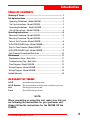
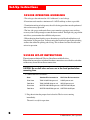
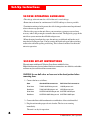
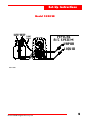
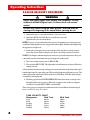
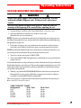
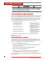
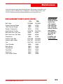
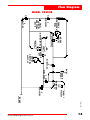
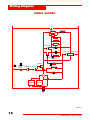
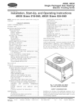
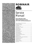
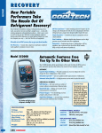
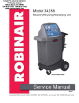
○ ○ ○ ○ ○ ○ ○ ○ ○ ○ ○ ○ ○ ○ ○ ○ ○ ○ ○ ○ ○ ○ ○ ○ ○ ○ ○ ○ ○ ○ ○ ○ ○ ○ ○ ○ ○ ○ ○ ○ ○ ○ ○ ○ ○ ○ ○ ○ ○ ○ ○ ○ ○ ○ ○ ○ ○ ○ ○ ○ ○ ○ ○ ○ ○ ○ ○ ○ ○ ○ ○ ○ ○ ○ ○ ○ ○
Operating Manual
Model 25200B/25202B
Refrigerant Recovery Unit
(Not for use in automotive R-134a applications)
ROBINAIR
Refrigerant Recovery Unit
Model: 25200B /25202B Series
Type of Equipment: Recovery
Refrigerants:
R-12, R-22, R-134a, R-401A, R-401B, R-402A,
R-402B, R-404A, R-407A, R-407B, R-407C, R-408A,
R-409A, R-410A, R-500, R-502, R-507
DESIGN PRESSURE:
High 435 psig
Low 336 psig
WARNING
PRESSURIZED TANK CONTAINS LIQUID REFRIGERANT. OVERFILLING OF THE TANK MAY CAUSE VIOLENT
EXPLOSION AND POSSIBLE INJURY OR DEATH. Use only authorized refrigerant tanks. Refer to this instruction
manual for tank specs. Do not recover refrigerants into a non-refillable storage container! Federal regulations require
refrigerant to be transported only in containers meeting DOT spec. 4BW or DOT spec. 4BA.
CAUTION: TO REDUCE THE RISK OF INJURY, care should be taken when moving this equipment.
ALL HOSES MAY CONTAIN LIQUID REFRIGERANT UNDER PRESSURE. Contact with refrigerant may cause injury.
Wear proper protective equipment, including safety goggles. Disconnect hoses with extreme caution.
HIGH VOLTAGE ELECTRICITY INSIDE PANELS. RISK OF ELECTRICAL SHOCK. Disconnect power before
servicing unit. Refer to this instruction manual.
TO REDUCE THE RISK OF FIRE,
avoid the use of an extension cord because the extension
cord may overheat. However, if you must use an extension cord, the cord must be No. 14 AWG minimum and kept as
short as possible. Do not use this equipment in the vicinity of spilled or open containers of gasoline or other flammable
substances. Use this equipment in locations with mechanical ventilation that provides at least four air changes per hour
or locate the equipment at least 18 inches above the floor. Make certain that all safety devices are functioning properly
before operating the unit. Before operating, read and follow the instructions and warnings in this operating manual.
Use only with refrigerants R-12, R-22, R-134a, R-401A, R-401B, R-402A, R-402B, R-404A, R-407A, R-407B,
R-407C, R-408A, R-409A, R-410A, R-500, R-502, R-507. This equipment is not designed for any other purpose
than recovering refrigerants! Do not mix refrigerant types.
CAUTION: SHOULD BE OPERATED BY QUALIFIED PERSONNEL. Operator must be familiar with air conditioning
and refrigeration systems, refrigerants and the dangers of pressurized components.
R-134a WARNINGS
Cross-contamination with other refrigerant types will cause severe damage to the A/C System and to service tools and equipment.
Do not mix refrigerant types through a system or in the same container!
Avoid breathing A/C refrigerant and lubricant vapor or mist. Exposure may irritate eyes, nose and throat. If accidental system
discharge occurs, ventilate work area before resuming service.
HFC-134a service equipment or vehicle A/C systems should not be pressure-tested or leak-tested with compressed air. Some
mixtures of air/HFC-134a have been shown to be combustible at elevated pressures. These mixtures are potentially dangerous and
may result in fire or explosion causing injory or property damage.
Additional health and safety information may be obtained from refrigerant and lubricant manufacturers.
OPERATING NOTES
At operating temperatures exceeding 120° F/49° C, wait 10 minutes between recovery jobs.
This equipment has been certified by ARI to meet EPA's minimum requirements for recovery and recycling equipment
intended for use with all HCFC appliances and other high pressure appliances.
U.S. Patents: 5,005,375; 5,203,177; 5,209,077. U.S. and Foreign Patents Pending. Manufactured by Robinair, SPX Corporation, Montpelier, OH 43543-1952 USA
Introduction
TABLE OF CONTENTS
Glossary of Terms........................................................................ 1
Set-Up Instructions ..................................................................... 2
Operating Guidelines - Model 25200B ........................................ 2
Set -Up Instructions - Model 25200B .......................................... 2
Operating Guidelines - Model 25202B ....................................... 4
Set-Up Instructions - Model 25202B ........................................... 4
Operating Instructions ................................................................ 6
Recovery Procedure - Model 25200B .......................................... 6
Recovery Procedure - Model 25202B .......................................... 7
Tank-to-Tank Transfer - Model 25200B ......................................... 8
HIGH PRESSURE Light - Model 25200B ..................................... 8
Tank-To-Tank Transfer - Model 25202B ........................................ 9
HIGH PRESSURE Light - Model 25202B ..................................... 9
Self-Clearing Procedures Both Units ......................................... 10
Maintenance .............................................................................. 11
Replacement Parts - Both Units ................................................ 11
Troubleshooting Tips - Both Units .............................................. 12
Flow Diagram - Model 25200B ................................................... 13
Wiring Diagram - Model 25200B ................................................ 14
Wiring Diagram - Model 25202B ................................................ 15
Limited Warranty ......................................................................... 16
GLOSSARY OF TERMS
A/C-R
Air conditioning or refrigeration.
A/C-R System
Unit
Tank
The air conditioning or refrigeration system being serviced.
The refrigerant recovery unit.
The refillable refrigerant tank.
NOTE:
When connecting or using this unit, make sure that you
are following the instructions for your particular unit.
Always follow the instructions for the 25200B OR the
25202B.
Model 25200B Refrigerant Recovery Unit
1
Set-Up Instructions
25200B OPERATING GUIDELINES
• The voltage at the unit must be +10% of the unit’s rated voltage.
• Extension cords must be a minimum of 14 AWG and kept as short as possible.
• To minimize mixing of refrigerants, the self-clearing procedure must be performed
after each recovery operation.
• The low side gauge on the unit allows you to monitor system pressure and stop
recovery when a deep enough vacuum has been reached. The high side gauge on the
unit allows you to monitor the refillable tank pressure.
• When changing from liquid to vapor, the unit may switch back and forth several
times before staying on vapor. You may notice the liquid and vapor lights switching
and hear the solenoids opening and closing. This is normal and does not affect the
unit or its operation.
25200B SET-UP INSTRUCTIONS
The unit comes with four 60” Enviro-Guard hoses with ball valves.
Either blue hose may be used where blue hose connections are called for, and either
red hose may be used for red hose connections.
CAUTION! Be sure ball valves on hoses are in the closed position before
connecting them.
1. Connect the hoses as follows:
Hose
Standard End connects to:
Ball Valve End connects to:
Blue Hose
TANK LIQUID fitting on unit
LIQUID port on tank
Red Hose
TANK VAPOR fitting on unit
VAPOR port on tank
Blue Hose
SYSTEM VAPOR fitting on unit SYSTEM VAPOR port
Red Hose
SYSTEM LIQUID fitting on unit SYSTEM LIQUID port
2. Plug the unit into the proper electrical outlet. The fan starts running
immediately.
The unit is ready for operation.
2
© 2000 Robinair, SPX Corporation
Set-Up Instructions
Model 25200B
Front View of Unit
LIQUID VAPOR
VALVE VALVE
INST0723
Model 25200B Refrigerant Recovery Unit
TYPICAL
A/C-R SYSTEM
VAPOR
LIQUID
Hose Connections
3
Set-Up Instructions
25202B OPERATING GUIDELINES
• The voltage at the unit must be +10% of the unit’s rated voltage.
• Extension cords must be a minimum of 14 AWG and kept as short as possible.
• To minimize mixing of refrigerants, the self-clearing procedure must be performed
after each recovery operation.
• The low side gauge on the unit allows you to monitor system pressure and stop
recovery when a deep enough vacuum has been reached. The high side gauge on the
unit allows you to monitor the refillable tank pressure.
• When changing from liquid to vapor, the unit may switch back and forth several
times before staying on vapor. You may notice the liquid and vapor lights switching
and hear the solenoids opening and closing. This is normal and does not affect the
unit or its operation.
25202B SET-UP INSTRUCTIONS
The unit comes with four 60” Enviro-Guard hoses with ball valves.
Either blue hose may be used where blue hose connections are called for, and either
red hose may be used for red hose connections.
CAUTION! Be sure ball valves on hoses are in the closed position before
connecting them.
1. Connect the hoses as follows:
Hose
Standard End connects to:
Ball Valve End connects to:
Blue Hose
TANK LIQUID fitting on unit
LIQUID port on tank
Red Hose
TANK VAPOR fitting on unit
VAPOR port on tank
Blue Hose
SYSTEM VAPOR fitting on unit SYSTEM VAPOR port
Red Hose
SYSTEM LIQUID fitting on unit SYSTEM LIQUID port
2. Connect the float cable from the unit to a tank that has a float switch installed.
3. Plug the unit into the proper electrical outlet. The fan starts running
immediately.
The unit is ready for operation.
4
© 2000 Robinair, SPX Corporation
Set-Up Instructions
Model 25202B
LIQUID VAPOR
VALVE VALVE
FLOAT
CABLE
TYPICAL
A/C SYSTEM
VAPOR
LIQUID
INST 0806
Model 25200B Refrigerant Recovery Unit
5
Operating Instructions
25200B RECOVERY PROCEDURE
WARNING
Always wear safety goggles when working with refrigerants. Use only
authorized refillable refrigerant tanks. Disconnect hoses with extreme
caution!
All hoses may contain refrigerant under pressure. Read and follow all
warnings at the beginning of this manual before operating the unit.
1. Connect the hoses as described in the Set-Up Instructions.
2. Open the LIQUID and VAPOR valves on the recovery tank.
Open the ball valves on all four hoses.
NOTE: It is necessary to monitor the tank capacity/weight while recovering to prevent
overfilling. During liquid recovery, refrigerant transfers rapidly. Monitor tank weight using
the appropriate weight scale.
3. Look at the system pressure gauge on the unit to be sure there is refrigerant pressure in the system. If there is no pressure, there is no refrigerant to be recovered.
NOTE: By taking the ambient temperature and using a pressure/temperature chart, you
can use this pressure to determine the type of refrigerant in the system.
4. Turn valve on the control panel to RECOVER.
5. Turn switch to RECOVER. The light on the switch illuminates and you will hear the
compressor start.
A float chamber monitors refrigerant being recovered and automatically adjusts the unit to
handle either liquid or vapor refrigerant. This provides for the most efficient recovery. The
amber lights on the control panel indicate the state (LIQUID or VAPOR) of the refrigerant currently entering the unit.
6. The blue gauge labeled SYSTEM PRESSURE shows the current system pressure
throughout the recovery process. When the system pressure reaches an adequate
vacuum level, turn the RECOVERY switch to OFF.
The recovery process is complete, but the unit must be cleared before disconnecting all
hoses (see Self-Clearing Procedure).
6
TANK CAPACITY CHART
Refrigerants
30 lb. Tank
50 lb. Tank
R-12
R-22
R-134a
R-407C
R-410A
40 lbs.
40 lbs.
41 lbs.
39 lbs.
36 lbs.
22 lbs.
22 lbs.
22 lbs.
21 lbs.
19 lbs.
© 2000 Robinair, SPX Corporation
Operating Instructions
25202B RECOVERY PROCEDURE
WARNING
Always wear safety goggles when working with refrigerants. Use only
authorized refillable refrigerant tanks. Disconnect hoses with extreme
caution!
All hoses may contain refrigerant under pressure. Read and follow all
warnings at the beginning of this manual before operating the unit.
1. Connect the hoses and float cable as described in the Set-Up Instructions.
2. Open the LIQUID and VAPOR valves on the recovery tank.
Open the ball valves on all four hoses.
NOTE: It is necessary to monitor the tank capacity/weight while recovering to prevent
overfilling. During liquid recovery, refrigerant transfers rapidly. Monitor tank weight using
the appropriate weight scale.
3. Look at the system pressure gauge on the unit to be sure there is refrigerant pressure in the system. If there is no pressure, there is no refrigerant to be recovered.
NOTE: By taking the ambient temperature and using a pressure/temperature chart, you
can use this pressure to determine the type of refrigerant in the system.
4. Turn valve on the control panel to RECOVER.
5. Turn switch to RECOVER. The light on the switch illuminates and you will hear the
compressor start.
A float chamber monitors refrigerant being recovered and automatically adjusts the unit to
handle either liquid or vapor refrigerant. This provides for the most efficient recovery. The
amber lights on the control panel indicate the state (LIQUID or VAPOR) of the refrigerant currently entering the unit.
6. The blue gauge labeled SYSTEM PRESSURE shows the current system pressure
throughout the recovery process. When the system pressure reaches an adequate
vacuum level, turn the RECOVERY switch to OFF.
The recovery process is complete, but the unit must be cleared before disconnecting all
hoses (see Self-Clearing Procedure).
TANK CAPACITY CHART
Refrigerants
30 lb. Tank
50 lb. Tank
R-12
R-22
R-134a
R-407C
R-410A
40 lbs.
40 lbs.
41 lbs.
39 lbs.
36 lbs.
22 lbs.
22 lbs.
22 lbs.
21 lbs.
19 lbs.
Model 25200B Refrigerant Recovery Unit
7
Operating Instructions
Op
WARNING
Be sure the refrigerant level in the tank does not exceed 80% of the tank
volume. Failure to monitor the level could result in excessive hydrostatic
pressures, causing physical injury or death.
25200B TANK-TO-TANK TRANSFER
If you are recovering refrigerant from one refillable tank into another, the color of the
hoses used for SYSTEM LIQUID and SYSTEM VAPOR may not match the color
of the liquid and vapor valves on the tank you are pulling refrigerant from. Be sure
the hose for SYSTEM LIQUID is connected to the liquid valve of the tank and the
hose for SYSTEM VAPOR is connected to the vapor valve of the tank.
1. Connect the hoses as follows:
Standard End connects to:
Ball Valve End connects to:
TANK LIQUID fitting on unit
LIQUID port on tank refrigerant
is being transferred into
TANK VAPOR fitting on unit
VAPOR port on tank refrigerant
is being transferred into
SYSTEM VAPOR fitting on unit
VAPOR port on tank refrigerant
is being transferred from
SYSTEM LIQUID fitting on unit
LIQUID port on tank refrigerant
is being transferred from
2. Follow Steps 1 through 6 in the Recovery Procedure on the previous page.
NOTE: Monitor tank weight.
HIGH PRESSURE (25200B)
If, during the recovery or self-clearing process, the HIGH PRESSURE light comes on,
make sure all appropriate valves are open. If the valves are open and the light is still on,
there is an excessive amount of air or the tank is full. Follow these steps:
1. Press the COMPRESSOR switch to OFF.
2. Close both valves on the refillable tank and close both valves on the red and blue
hoses connected to the tank.
3. Disconnect the red hose and the blue hose from the refillable tank.
4. Replace this tank with an empty refillable tank.
5. Reconnect the hoses as described in the Set-Up Instructions. Then follow the
steps in either the Recovery Procedure or the Self-Clearing Procedure.
If, after completing the above steps, either light is still on, call the Technical Support Line
at (800) 822-5561.
8
© 2000 Robinair, SPX Corporation
perating Instructions
Operating Instructions
WARNING
Be sure the refrigerant level in the tank does not exceed 80% of the tank
volume. Failure to monitor the level could result in excessive hydrostatic
pressures, causing physical injury or death.
25202B TANK-TO-TANK TRANSFER
If you are recovering refrigerant from one refillable tank into another, the color of the
hoses used for SYSTEM LIQUID and SYSTEM VAPOR may not match the color
of the liquid and vapor valves on the tank you are pulling refrigerant from. Be sure
the hose for SYSTEM LIQUID is connected to the liquid valve of the tank and the
hose for SYSTEM VAPOR is connected to the vapor valve of the tank.
1. Connect the hoses as follows:
Standard End connects to:
Ball Valve End connects to:
TANK LIQUID fitting on unit
LIQUID port on tank refrigerant
is being transferred into
TANK VAPOR fitting on unit
VAPOR port on tank refrigerant
is being transferred into
SYSTEM VAPOR fitting on unit
VAPOR port on tank refrigerant
is being transferred from
SYSTEM LIQUID fitting on unit
LIQUID port on tank refrigerant
is being transferred from
2. Follow Steps 1 through 6 in the Recovery Procedure on the previous page.
NOTE: Monitor tank weight.
HIGH PRESSURE (25202B)
If, during the recovery or self-clearing process, the HIGH PRESSURE light comes on,
make sure all appropriate valves are open. If the valves are open and the light is still on,
there is an excessive amount of air or the tank is full. Follow these steps:
1. Press the COMPRESSOR switch to OFF.
2. Close both valves on the refillable tank and close both valves on the red and blue
hoses connected to the tank.
3. Disconnect the red hose and the blue hose, along with the float cable, from the
refillable tank.
4. Replace this tank with an empty refillable tank.
5. Reconnect the hoses and float cable as described in the Set-Up Instructions. Then
follow the steps in either the Recovery Procedure or the Self-Clearing Procedure.
If, after completing the above steps, either light is still on, call the Technical Support Line
at (800) 822-5561.
Model 25200B Refrigerant Recovery Unit
9
Operating Instructions
SELF-CLEARING PROCEDURE (BOTH UNITS)
CAUTION! Do not mix refrigerant types. Always perform the self-clearing
procedure after each recovery. Beginning each job with a “clean” unit will
help eliminate mixing of different refrigerant types.
1. Close the ball valves on the red and blue hoses connected to the A/C-R
system. Disconnect these hoses from the system’s access ports.
2. Close the blue LIQUID valve on the tank and the ball valve on the blue
TANK LIQUID hose. Disconnect the TANK LIQUID hose from the tank.
3. Check to be sure the red TANK VAPOR hose is still connected to the red
VAPOR fitting on the tank. Both the tank’s red VAPOR valve and the ball
valve on the red TANK VAPOR hose should be open.
4. Turn the valve on the control panel to SELF-CLEAR.
5. Press the switch to SELF-CLEAR. You will hear the compressor start and
the switch will illuminate.
6. Let the compressor run until the system pressure gauge reaches the appropriate vacuum level. The System Pressure gauge will return to VACUUM. Press
the COMPRESSOR switch to OFF. Unplug the unit from the electrical
source.
7. Close the red VAPOR valve on the tank and the ball valve on the red TANK
VAPOR hose. Disconnect the TANK VAPOR hose from the tank.
WARNING
Disconnect hoses with extreme caution! All hoses may contain
refrigerant under pressure.
8.
10
While the hoses are still connected to the unit, slowly open the ball valve on
each hose to relieve any pressure in the hose. Close the ball valves, then
disconnect the hoses from the unit.
© 2000 Robinair, SPX Corporation
Maintenance
Your unit has been designed for minimal maintenance. The compressor should be evaluated for wear after 2,500 hours of use. Call Robinair’s Technical Support Line, (800)
822-5561, for the location of an authorized Robinair service center near you.
REPLACEMENT PARTS (BOTH UNITS)
Ball Valve
System Pressure Gauge
Tank Pressure Gauge
Switch—Compressor
High Pressure Cut-Out
Ball Valve Hose—60” Red
Ball Valve Hose—60” Blue
Compressor
Indicator Light, Red
Indicator Light, Amber
Fan
Float Chamber
Relay Board
Case Bottom
Case Back
Case Front
Float Cable & Relay
Model 25200B Refrigerant Recovery Unit
115v
RA19664
19666
19667
19670
RA19720
65360
65260
19652
RA17106
RA17107
RA17416
19685
19662
19663
19665
19667
19497
230v
RA19664
19705
19708
19704
RA19720
65360
65260
19706
RA19349
RA19351
RA17516
19685
19703
19663
19665
19667
19498
CAUTION!
Clean the shroud
and/or base
with standard
soap and water
only. Industrial
solvents found in
most cleaners
and degreasers
can cause the
plastic to
crystallize and
become brittle.
11
Troubleshooting Tips
Compressor does not start
Problem: Compressor circuit breaker has tripped
Solution: Depress the circuit breaker switch
Problem: HIGH PRESSURE light is on
Solution: The high side pressure switch has tripped; Verify that the tank
and hose ball valves are open. Check tank and verify that it is
not full
Problem: COMPRESSOR switch is not on
Solution: Press the COMPRESSOR switch to ON
Compressor runs but does not move refrigerant
Problem: Valve is not in the RECOVER position
Solution:
Problem:
Solution:
Problem:
Solution:
Turn Valve to RECOVER
The ball valves on the hoses are not open
Open the ball valves
The tank valves are not open
Open the valves
During recovery, unit shuts off on high pressure
Problem: The refillable tank valves are not open
Solution: Open the tank valves
Problem: Valves on hoses are shut
Solution: Open valves
Unit will not pull down to appropriate vacuum level
Problem: There is a leak in the A/C system
Solution: Fix the leak
Problem: Trapped pockets of refrigerant
Solution: Allow system to stabilize then heat with a heat gun
TANK FULL Light is On
Problem: Tank float cable is diconnected at front_____
Solution: Connect the float cable to the tank.
Problem: Recovery tank is full.
Solution: Change the recovery tank.
12
© 2000 Robinair, SPX Corporation
Model 25200B Refrigerant Recovery Unit
INST0722
SYSTEM
LIQUID
FLOAT
CHAMBER
SOLENOID
3
SYSTEM
VAPOR
SOLENOID
5
TANK
CHECK
VALVE
SOLENOID
1
EXP.
VALVE
SYSTEM
PRESSURE
GAUGE
INTAKE
SELF-CLR
TANK
VAPOR
RECOVER
COMPRESSOR
DISCHARGE
TANK
PRESSURE
GAUGE
SOLENOID
2
HIGH
PRESSURE
CUT OUT
(435)
(470)
SOLENOID
4
Flow Diagram
MODEL 25200B
13
Wiring Diagram
MODEL 25200B
N
L
110 V
LIQ/VAP RELAY
FLOAT
CHAMBER
RL1:A
MOV
SOL1 N.C.
SOL2 N.C.
SOL3 N.C.
LIQ/VAP RELAY
A
VAPOR LP1
RL1:B
A
CLEAR RELAY
POWER SWITCH
LIQUID LP2
RL3:B
B
SOL5 N.C.
RL3:C
SW1:B
CLEAR RELAY
CLEAR RELAY
RL3:A
C1
C
CIRCUIT
BREAKER
COMPRESSOR
THERMAL
CUT-OUT
H.P. SWITCH
POWER SWITCH
SOL4 N.C.
H.P. RELAY RL2:A
H.P. RELAY
SW2
SW1:A
B1
RL2:A
RL2:B
R
BRIDGE
COMPRESSOR
HIGH PRESSURE
LP3
CAPACITOR
FAN
INST0721
14
© 2000 Robinair, SPX Corporation
Wiring Diagram
MODEL 25202B
L
N
100 V
LIQ/VAP RELAY
FLOAT
CHAMBER
RL1:A
MOV
SOL1 N.C.
SOL2 N.C.
SOL3 N.C.
LIQ/VAP RELAY
A
VAPOR LP1
RL1:B
A
CLEAR RELAY
POWER SWITCH
LIQUID LP2
RL3:B
SOL5 N.C.
RL3:C
SW1:B
CLEAR RELAY
CLEAR RELAY
RL3:A
SOL4 N.C.
H.P. SWITCH
CIRCUIT
BREAKER
FLOAT RELAY
COMPRESSOR
THERMAL
CUT-OUT
RL4:B
POWER SWITCH
SW1:A
H.P. RELAY
H.P. RELAY
SW2
RL2:A
RL2:B
R
BRIDGE
COMPRESSOR
TANK FLOAT
HIGH PRESSURE
LP3
CAPACITOR
FLOAT RELAY
RL4:A
FAN
INST0807
Model 25200B Refrigerant Recovery Unit
15
Notes
Model 25200B Refrigerant Recovery Unit
Limited Warranty
This product is warranted to be free from defects in workmanship, materials, and
components for a period of one year from date of purchase. All parts and labor required
to repair defective products covered under the warranty will be at no charge.
The following restrictions apply:
1. The limited warranty applies to the original purchaser only.
2. The warranty applies to the product in normal usage situations only, as described in
this operating manual. The product must also be serviced and maintained as specified.
3. If the product fails, it will be repaired or replaced at the option of the manufacturer.
4. Warranty service is provided by our network of authorized service centers. Call the
toll-free Technical Support Line, (800) 822-5561, for service authorization and the
location of the nearest service center. Do not ship or deliver units to a service
center without authorization. Do not ship units to the factory.
5. Warranty service claims are subject to factory inspection for product defect(s). The
factory or service center personnel are the sole determiners of warranty coverage.
6. The manufacturer shall not be responsible for any additional costs associated with a
product failure including, but not limited to, loss of work time, loss of refrigerant,
and unauthorized shipping and/or labor charges.
7. All warranty service claims must be made within the specified warranty period.
Proof-of-purchase date must be supplied to the manufacturer.
8. Use of this recovery equipment with unauthorized refrigerants will void our warranty. Authorized refrigerants are listed on the equipment or are available through
our Technical Service Department.
This Limited Warranty does not apply if:
• The product, or product part, is broken by accident.
• The product is misused, tampered with or modified.
• The product is used for recovering any substance other than the specified
refrigerant type.
16
© 2000 Robinair, SPX Corporation
CONVERSION
TABLE
OZ.
LBS.
0.5
1.0
1.5
2.0
2.5
3.0
3.5
4.0
4.5
5.0
5.5
6.0
6.5
7.0
7.5
8.0
8.5
9.0
9.5
10.0
10.5
11.0
11.5
12.0
12.5
13.0
13.5
14.0
14.5
15.0
15.5
16.0
0.03
0.06
0.09
0.13
0.16
0.19
0.22
0.25
0.28
0.31
0.34
0.38
0.41
0.44
0.47
0.50
0.53
0.56
0.59
0.63
0.69
0.69
0.72
0.75
0.78
0.81
0.84
0.88
0.91
0.94
0.97
1 lb.
Visit our web site at
www.robinair.com
or
call our toll-free
Technical Support Line
800-822-5561
in the continental U.S. and Canada.
☎
In all other locations, contact your local distributor. To help us serve
you better, please be prepared to provide the model number, serial
number, and date of purchase.
To validate your warranty, you must complete the warranty card
attached to your unit and return it within ten days from date of
purchase.
• NATIONWIDE NETWORK OF AUTHORIZED SERVICE CENTERS
If your unit needs repairs or replacement parts, you should
contact the service center in your area. For help in locating a
service center, call the toll free technical support line.
Due to ongoing product improvements,
we reserve the right to change design,
specifications and materials without notice.
SPX ROBINAIR
SPX Corporation
1224 Robinair Way, Box 193
Montpelier OH 43543-0193 USA
Phone 419-485-5561
Fax 419-485-8300
Web site: www.robinair.com
123220 (4/00)
Model 25200B/25202B Refrigerant Recovery Unit
Printed In USA