1
ViewScape Toolset
User Guide
R5976476/03
01/07/2004
Product revision
Software version: 1.1
Barco nv Events
Noordlaan 5, B-8520 Kuurne
Phone: +32 56.36.89.70
Fax: +32 56.36.88.24
E-mail: [email protected]
Visit us at the web: www.barco.com
Printed in Belgium
Copyright ©
All rights reserved. No part of this document may be copied, reproduced or translated. It shall not otherwise
be recorded, transmitted or stored in a retrieval system without the prior written consent of Barco.
Trademarks
Brand and product names mentioned in this manual may be trademarks, registered trademarks or copyrights
of their respective holders. All brand and product names mentioned in this manual serve as comments or
examples and are not to be understood as advertising for the products or their manufactures.
Software Licence Agreement
User agreement for ViewScape Toolset Software
IMPORTANT: This Software Agreement is a legal agreement between the end user and the producer of the software product identified above, which includes computer software and associated media and printed materials,
and includes “online” or electronic documentation. By installing, copying, or otherwise using the SOFTWARE
PRODUCT, you agree to be bound by the terms of this Agreement.
The SOFTWARE PRODUCT is protected by copyright laws and international copyright treaties, as well as other
intellectual property laws and treaties.
Systems Software - You may install and use this SOFTWARE PRODUCT only in conjunction with other Barco
products where it is made for.
If you have acquired this software with the purchase of a product you may make a number of additional copies
of the computer software portion of the SOFTWARE PRODUCT only for authorized training off line for a Barco
System.
RIGHTS AND LIMITATIONS. You may not reverse engineer, decompile, or disassemble the SOFTWARE
PRODUCT.
NO LIABILITY FOR CONSEQUENTIAL DAMAGES To the maximum extent permitted by applicable law, in
no event shall the manufacturer or it’s suppliers be liable for any special, incidental, indirect, or consequential
damages whatsoever (including, without limitation, damages for loss of business profits, business interruption,
loss of business information, or any other pecuniary loss) arising out of the use of or inability to use the software
product, even if the manufacturer has been advised of the possibility of such damages.
Table of contents
TABLE OF CONTENTS
1. Introduction ..........................................................................................5
1.1 General introduction . . . . . . . . . . . . . . . . . . . . . . . . . . . . . . . . . . . . . . . . . . . . . . . . . . . . . . . . . . . . . . . . . . . . . . . . . . . . . . . . . . . . . . . . . . . . 5
2. Installation............................................................................................7
2.1
2.2
2.3
2.4
General Requirements . . . . . . . . . . . . . . . . . . . . . . . . . . . . . . . . . . . . . . . . . . . . . . . . . . . . . . . . . . . . . . . . . . . . . . . . . . . . . . . . . . . . . . . . . 7
Software installation . . . . . . . . . . . . . . . . . . . . . . . . . . . . . . . . . . . . . . . . . . . . . . . . . . . . . . . . . . . . . . . . . . . . . . . . . . . . . . . . . . . . . . . . . . . . 7
Starting up . . . . . . . . . . . . . . . . . . . . . . . . . . . . . . . . . . . . . . . . . . . . . . . . . . . . . . . . . . . . . . . . . . . . . . . . . . . . . . . . . . . . . . . . . . . . . . . . . . . . . . . 9
Closing . . . . . . . . . . . . . . . . . . . . . . . . . . . . . . . . . . . . . . . . . . . . . . . . . . . . . . . . . . . . . . . . . . . . . . . . . . . . . . . . . . . . . . . . . . . . . . . . . . . . . . . . . . 11
3. Configuration Wizard ............................................................................ 13
3.1 The wizard window . . . . . . . . . . . . . . . . . . . . . . . . . . . . . . . . . . . . . . . . . . . . . . . . . . . . . . . . . . . . . . . . . . . . . . . . . . . . . . . . . . . . . . . . . . . . 13
3.2 Set up paths . . . . . . . . . . . . . . . . . . . . . . . . . . . . . . . . . . . . . . . . . . . . . . . . . . . . . . . . . . . . . . . . . . . . . . . . . . . . . . . . . . . . . . . . . . . . . . . . . . . . 13
3.3 Creating a new configuration . . . . . . . . . . . . . . . . . . . . . . . . . . . . . . . . . . . . . . . . . . . . . . . . . . . . . . . . . . . . . . . . . . . . . . . . . . . . . . . . . 14
3.3.1 Based on ViewScape devices . . . . . . . . . . . . . . . . . . . . . . . . . . . . . . . . . . . . . . . . . . . . . . . . . . . . . . . . . . . . . . . . . . . . . . . . . . 14
3.3.1.1 Getting started . . . . . . . . . . . . . . . . . . . . . . . . . . . . . . . . . . . . . . . . . . . . . . . . . . . . . . . . . . . . . . . . . . . . . . . . . . . . . . . . . . . . . . 14
3.3.1.2 Set up . . . . . . . . . . . . . . . . . . . . . . . . . . . . . . . . . . . . . . . . . . . . . . . . . . . . . . . . . . . . . . . . . . . . . . . . . . . . . . . . . . . . . . . . . . . . . . . . 15
3.3.2 Based on the output requirements (resolution) . . . . . . . . . . . . . . . . . . . . . . . . . . . . . . . . . . . . . . . . . . . . . . . . . . . . . . . 17
3.3.2.1 Getting started . . . . . . . . . . . . . . . . . . . . . . . . . . . . . . . . . . . . . . . . . . . . . . . . . . . . . . . . . . . . . . . . . . . . . . . . . . . . . . . . . . . . . . 17
3.3.2.2 Set up . . . . . . . . . . . . . . . . . . . . . . . . . . . . . . . . . . . . . . . . . . . . . . . . . . . . . . . . . . . . . . . . . . . . . . . . . . . . . . . . . . . . . . . . . . . . . . . . 18
3.3.3 Creating a configuration starting from last saved file . . . . . . . . . . . . . . . . . . . . . . . . . . . . . . . . . . . . . . . . . . . . . . . . . 19
3.3.4 Current Configuration . . . . . . . . . . . . . . . . . . . . . . . . . . . . . . . . . . . . . . . . . . . . . . . . . . . . . . . . . . . . . . . . . . . . . . . . . . . . . . . . . . . . 19
3.3.5 Digitizer output selection . . . . . . . . . . . . . . . . . . . . . . . . . . . . . . . . . . . . . . . . . . . . . . . . . . . . . . . . . . . . . . . . . . . . . . . . . . . . . . . . 20
3.3.6 Defining the working windows . . . . . . . . . . . . . . . . . . . . . . . . . . . . . . . . . . . . . . . . . . . . . . . . . . . . . . . . . . . . . . . . . . . . . . . . . . 21
3.3.7 Removing windows out of the list. . . . . . . . . . . . . . . . . . . . . . . . . . . . . . . . . . . . . . . . . . . . . . . . . . . . . . . . . . . . . . . . . . . . . . . 22
3.3.8 Configuration preview . . . . . . . . . . . . . . . . . . . . . . . . . . . . . . . . . . . . . . . . . . . . . . . . . . . . . . . . . . . . . . . . . . . . . . . . . . . . . . . . . . . 22
3.3.9 Autodetection of connected devices . . . . . . . . . . . . . . . . . . . . . . . . . . . . . . . . . . . . . . . . . . . . . . . . . . . . . . . . . . . . . . . . . . . 23
3.3.9.1 RS232 Communication Settings . . . . . . . . . . . . . . . . . . . . . . . . . . . . . . . . . . . . . . . . . . . . . . . . . . . . . . . . . . . . . . . . . . 23
3.3.9.2 Start Autodetection . . . . . . . . . . . . . . . . . . . . . . . . . . . . . . . . . . . . . . . . . . . . . . . . . . . . . . . . . . . . . . . . . . . . . . . . . . . . . . . . . 25
3.3.9.3 Serial Numbers . . . . . . . . . . . . . . . . . . . . . . . . . . . . . . . . . . . . . . . . . . . . . . . . . . . . . . . . . . . . . . . . . . . . . . . . . . . . . . . . . . . . . 26
3.3.10 Compare Autodetected configuration – Created configuration . . . . . . . . . . . . . . . . . . . . . . . . . . . . . . . . . . . . . . 27
3.3.11 Updating the configuration . . . . . . . . . . . . . . . . . . . . . . . . . . . . . . . . . . . . . . . . . . . . . . . . . . . . . . . . . . . . . . . . . . . . . . . . . . . . . . 28
3.3.12 Output check . . . . . . . . . . . . . . . . . . . . . . . . . . . . . . . . . . . . . . . . . . . . . . . . . . . . . . . . . . . . . . . . . . . . . . . . . . . . . . . . . . . . . . . . . . . . . 29
3.3.13 Mechanical overlap setup . . . . . . . . . . . . . . . . . . . . . . . . . . . . . . . . . . . . . . . . . . . . . . . . . . . . . . . . . . . . . . . . . . . . . . . . . . . . . . . 32
3.3.14 Input Balance Adjustment . . . . . . . . . . . . . . . . . . . . . . . . . . . . . . . . . . . . . . . . . . . . . . . . . . . . . . . . . . . . . . . . . . . . . . . . . . . . . . . 34
3.3.15 Gamma setup – Soft edge blending . . . . . . . . . . . . . . . . . . . . . . . . . . . . . . . . . . . . . . . . . . . . . . . . . . . . . . . . . . . . . . . . . . . 34
3.3.16 Contrast and Color equalization . . . . . . . . . . . . . . . . . . . . . . . . . . . . . . . . . . . . . . . . . . . . . . . . . . . . . . . . . . . . . . . . . . . . . . . . 35
3.3.17 Black level Adjustment of the images . . . . . . . . . . . . . . . . . . . . . . . . . . . . . . . . . . . . . . . . . . . . . . . . . . . . . . . . . . . . . . . . . . 36
3.3.18 Loading final settings . . . . . . . . . . . . . . . . . . . . . . . . . . . . . . . . . . . . . . . . . . . . . . . . . . . . . . . . . . . . . . . . . . . . . . . . . . . . . . . . . . . . 37
3.3.19 Finishing the wizard. . . . . . . . . . . . . . . . . . . . . . . . . . . . . . . . . . . . . . . . . . . . . . . . . . . . . . . . . . . . . . . . . . . . . . . . . . . . . . . . . . . . . . 38
3.4 Loading a saved configuration . . . . . . . . . . . . . . . . . . . . . . . . . . . . . . . . . . . . . . . . . . . . . . . . . . . . . . . . . . . . . . . . . . . . . . . . . . . . . . . 39
4. The ViewScape application..................................................................... 41
4.1 Menu structure overview . . . . . . . . . . . . . . . . . . . . . . . . . . . . . . . . . . . . . . . . . . . . . . . . . . . . . . . . . . . . . . . . . . . . . . . . . . . . . . . . . . . . . . 41
4.2 Display selection . . . . . . . . . . . . . . . . . . . . . . . . . . . . . . . . . . . . . . . . . . . . . . . . . . . . . . . . . . . . . . . . . . . . . . . . . . . . . . . . . . . . . . . . . . . . . . . 42
5. RS232 Set up....................................................................................... 43
5.1 Start up . . . . . . . . . . . . . . . . . . . . . . . . . . . . . . . . . . . . . . . . . . . . . . . . . . . . . . . . . . . . . . . . . . . . . . . . . . . . . . . . . . . . . . . . . . . . . . . . . . . . . . . . . 43
5.2 Quick status change of RS232 . . . . . . . . . . . . . . . . . . . . . . . . . . . . . . . . . . . . . . . . . . . . . . . . . . . . . . . . . . . . . . . . . . . . . . . . . . . . . . . 44
6. Autodetect page................................................................................... 45
6.1 Start up of the Autodetect page . . . . . . . . . . . . . . . . . . . . . . . . . . . . . . . . . . . . . . . . . . . . . . . . . . . . . . . . . . . . . . . . . . . . . . . . . . . . . . 45
6.2 Actions on the Autodetection page . . . . . . . . . . . . . . . . . . . . . . . . . . . . . . . . . . . . . . . . . . . . . . . . . . . . . . . . . . . . . . . . . . . . . . . . . . 46
7. Windowing ......................................................................................... 47
7.1
7.2
7.3
7.4
Input and Display configuration . . . . . . . . . . . . . . . . . . . . . . . . . . . . . . . . . . . . . . . . . . . . . . . . . . . . . . . . . . . . . . . . . . . . . . . . . . . . . . 47
Selecting a Window . . . . . . . . . . . . . . . . . . . . . . . . . . . . . . . . . . . . . . . . . . . . . . . . . . . . . . . . . . . . . . . . . . . . . . . . . . . . . . . . . . . . . . . . . . . 48
Moving a window . . . . . . . . . . . . . . . . . . . . . . . . . . . . . . . . . . . . . . . . . . . . . . . . . . . . . . . . . . . . . . . . . . . . . . . . . . . . . . . . . . . . . . . . . . . . . . 48
Scaling Windows. . . . . . . . . . . . . . . . . . . . . . . . . . . . . . . . . . . . . . . . . . . . . . . . . . . . . . . . . . . . . . . . . . . . . . . . . . . . . . . . . . . . . . . . . . . . . . . 49
R5976476 VIEWSCAPE TOOLSET 01/07/2004
1
Table of contents
7.5 Making group changes to a window . . . . . . . . . . . . . . . . . . . . . . . . . . . . . . . . . . . . . . . . . . . . . . . . . . . . . . . . . . . . . . . . . . . . . . . . . 50
7.6 Z-Order . . . . . . . . . . . . . . . . . . . . . . . . . . . . . . . . . . . . . . . . . . . . . . . . . . . . . . . . . . . . . . . . . . . . . . . . . . . . . . . . . . . . . . . . . . . . . . . . . . . . . . . . . 50
7.7 Aspect Ratio. . . . . . . . . . . . . . . . . . . . . . . . . . . . . . . . . . . . . . . . . . . . . . . . . . . . . . . . . . . . . . . . . . . . . . . . . . . . . . . . . . . . . . . . . . . . . . . . . . . . 52
7.8 Changing a window name . . . . . . . . . . . . . . . . . . . . . . . . . . . . . . . . . . . . . . . . . . . . . . . . . . . . . . . . . . . . . . . . . . . . . . . . . . . . . . . . . . . . 52
7.9 Changing the window mode . . . . . . . . . . . . . . . . . . . . . . . . . . . . . . . . . . . . . . . . . . . . . . . . . . . . . . . . . . . . . . . . . . . . . . . . . . . . . . . . . . 53
7.10 Locking a window . . . . . . . . . . . . . . . . . . . . . . . . . . . . . . . . . . . . . . . . . . . . . . . . . . . . . . . . . . . . . . . . . . . . . . . . . . . . . . . . . . . . . . . . . . . . . . 54
7.11 Creating a full window . . . . . . . . . . . . . . . . . . . . . . . . . . . . . . . . . . . . . . . . . . . . . . . . . . . . . . . . . . . . . . . . . . . . . . . . . . . . . . . . . . . . . . . . . 54
7.12 ViewPort . . . . . . . . . . . . . . . . . . . . . . . . . . . . . . . . . . . . . . . . . . . . . . . . . . . . . . . . . . . . . . . . . . . . . . . . . . . . . . . . . . . . . . . . . . . . . . . . . . . . . . . . 55
7.12.1 General. . . . . . . . . . . . . . . . . . . . . . . . . . . . . . . . . . . . . . . . . . . . . . . . . . . . . . . . . . . . . . . . . . . . . . . . . . . . . . . . . . . . . . . . . . . . . . . . . . . . 55
7.12.2 Creating a ViewPort for a single source . . . . . . . . . . . . . . . . . . . . . . . . . . . . . . . . . . . . . . . . . . . . . . . . . . . . . . . . . . . . . . . 56
7.12.3 Creating a viewport for a multiple ’independent’ (hard edged) background . . . . . . . . . . . . . . . . . . . . . . . 58
7.12.4 Creating a viewport for a multiple ’overlapped’ background . . . . . . . . . . . . . . . . . . . . . . . . . . . . . . . . . . . . . . . . . 59
7.12.5 Making group changes to the viewport . . . . . . . . . . . . . . . . . . . . . . . . . . . . . . . . . . . . . . . . . . . . . . . . . . . . . . . . . . . . . . . . 60
7.12.6 Apply Viewport setting source 1 to source 2 . . . . . . . . . . . . . . . . . . . . . . . . . . . . . . . . . . . . . . . . . . . . . . . . . . . . . . . . . . 60
7.13 Visibility setup of a source . . . . . . . . . . . . . . . . . . . . . . . . . . . . . . . . . . . . . . . . . . . . . . . . . . . . . . . . . . . . . . . . . . . . . . . . . . . . . . . . . . . . 61
7.14 Color key. . . . . . . . . . . . . . . . . . . . . . . . . . . . . . . . . . . . . . . . . . . . . . . . . . . . . . . . . . . . . . . . . . . . . . . . . . . . . . . . . . . . . . . . . . . . . . . . . . . . . . . . 62
7.15 Alpha Blending . . . . . . . . . . . . . . . . . . . . . . . . . . . . . . . . . . . . . . . . . . . . . . . . . . . . . . . . . . . . . . . . . . . . . . . . . . . . . . . . . . . . . . . . . . . . . . . . . 64
7.16 Settings . . . . . . . . . . . . . . . . . . . . . . . . . . . . . . . . . . . . . . . . . . . . . . . . . . . . . . . . . . . . . . . . . . . . . . . . . . . . . . . . . . . . . . . . . . . . . . . . . . . . . . . . . 66
7.17 Work Space Resolution . . . . . . . . . . . . . . . . . . . . . . . . . . . . . . . . . . . . . . . . . . . . . . . . . . . . . . . . . . . . . . . . . . . . . . . . . . . . . . . . . . . . . . . 66
7.18 Preset Configurations . . . . . . . . . . . . . . . . . . . . . . . . . . . . . . . . . . . . . . . . . . . . . . . . . . . . . . . . . . . . . . . . . . . . . . . . . . . . . . . . . . . . . . . . . 67
7.18.1 Saving a configuration . . . . . . . . . . . . . . . . . . . . . . . . . . . . . . . . . . . . . . . . . . . . . . . . . . . . . . . . . . . . . . . . . . . . . . . . . . . . . . . . . . . 67
7.18.2 Loading a configuration, way 1 . . . . . . . . . . . . . . . . . . . . . . . . . . . . . . . . . . . . . . . . . . . . . . . . . . . . . . . . . . . . . . . . . . . . . . . . . 68
7.18.3 Loading a configuration, way 2 . . . . . . . . . . . . . . . . . . . . . . . . . . . . . . . . . . . . . . . . . . . . . . . . . . . . . . . . . . . . . . . . . . . . . . . . . 69
7.18.4 Loading a configuration, way 3 . . . . . . . . . . . . . . . . . . . . . . . . . . . . . . . . . . . . . . . . . . . . . . . . . . . . . . . . . . . . . . . . . . . . . . . . . 70
7.18.5 Removing a predefined configuration . . . . . . . . . . . . . . . . . . . . . . . . . . . . . . . . . . . . . . . . . . . . . . . . . . . . . . . . . . . . . . . . . . 70
8. Configuration Manager .......................................................................... 73
8.1
8.2
8.3
8.4
8.5
Overview of the configuration manager . . . . . . . . . . . . . . . . . . . . . . . . . . . . . . . . . . . . . . . . . . . . . . . . . . . . . . . . . . . . . . . . . . . . . 73
Saving a Configuration . . . . . . . . . . . . . . . . . . . . . . . . . . . . . . . . . . . . . . . . . . . . . . . . . . . . . . . . . . . . . . . . . . . . . . . . . . . . . . . . . . . . . . . . 74
“Save as” a Configuration. . . . . . . . . . . . . . . . . . . . . . . . . . . . . . . . . . . . . . . . . . . . . . . . . . . . . . . . . . . . . . . . . . . . . . . . . . . . . . . . . . . . . 75
Deleting a Configuration . . . . . . . . . . . . . . . . . . . . . . . . . . . . . . . . . . . . . . . . . . . . . . . . . . . . . . . . . . . . . . . . . . . . . . . . . . . . . . . . . . . . . . 76
Loading a Configuration. . . . . . . . . . . . . . . . . . . . . . . . . . . . . . . . . . . . . . . . . . . . . . . . . . . . . . . . . . . . . . . . . . . . . . . . . . . . . . . . . . . . . . . 78
9. Preferences ........................................................................................ 81
9.1
9.2
9.3
9.4
Purpose of the preferences set up . . . . . . . . . . . . . . . . . . . . . . . . . . . . . . . . . . . . . . . . . . . . . . . . . . . . . . . . . . . . . . . . . . . . . . . . . . . 81
Start up the preferences . . . . . . . . . . . . . . . . . . . . . . . . . . . . . . . . . . . . . . . . . . . . . . . . . . . . . . . . . . . . . . . . . . . . . . . . . . . . . . . . . . . . . . 81
Adjusting the window offset. . . . . . . . . . . . . . . . . . . . . . . . . . . . . . . . . . . . . . . . . . . . . . . . . . . . . . . . . . . . . . . . . . . . . . . . . . . . . . . . . . . 82
Changing the Screen position . . . . . . . . . . . . . . . . . . . . . . . . . . . . . . . . . . . . . . . . . . . . . . . . . . . . . . . . . . . . . . . . . . . . . . . . . . . . . . . . 82
10.ViewScape Configuration ...................................................................... 83
10.1 ViewScape Configuration start up. . . . . . . . . . . . . . . . . . . . . . . . . . . . . . . . . . . . . . . . . . . . . . . . . . . . . . . . . . . . . . . . . . . . . . . . . . . . 83
10.2 ViewScape Settings . . . . . . . . . . . . . . . . . . . . . . . . . . . . . . . . . . . . . . . . . . . . . . . . . . . . . . . . . . . . . . . . . . . . . . . . . . . . . . . . . . . . . . . . . . . 84
10.2.1 Operational Mode . . . . . . . . . . . . . . . . . . . . . . . . . . . . . . . . . . . . . . . . . . . . . . . . . . . . . . . . . . . . . . . . . . . . . . . . . . . . . . . . . . . . . . . . 84
10.2.2 Output Selection. . . . . . . . . . . . . . . . . . . . . . . . . . . . . . . . . . . . . . . . . . . . . . . . . . . . . . . . . . . . . . . . . . . . . . . . . . . . . . . . . . . . . . . . . . 85
10.2.3 Timings . . . . . . . . . . . . . . . . . . . . . . . . . . . . . . . . . . . . . . . . . . . . . . . . . . . . . . . . . . . . . . . . . . . . . . . . . . . . . . . . . . . . . . . . . . . . . . . . . . . . 85
10.2.3.1Using predefined timings for digital or analog output . . . . . . . . . . . . . . . . . . . . . . . . . . . . . . . . . . . . . . . . . . . 86
10.2.3.2Using the advanced timing settings for digital or analog output . . . . . . . . . . . . . . . . . . . . . . . . . . . . . . . 86
10.2.3.3Timings of Sync Generator for Digital or Analog output . . . . . . . . . . . . . . . . . . . . . . . . . . . . . . . . . . . . . . . . 88
10.2.3.4Timings of Display Interface for Digital or Analog output . . . . . . . . . . . . . . . . . . . . . . . . . . . . . . . . . . . . . . . 90
10.2.4 Pattern Generation. . . . . . . . . . . . . . . . . . . . . . . . . . . . . . . . . . . . . . . . . . . . . . . . . . . . . . . . . . . . . . . . . . . . . . . . . . . . . . . . . . . . . . . 91
10.2.4.1Overview and activation . . . . . . . . . . . . . . . . . . . . . . . . . . . . . . . . . . . . . . . . . . . . . . . . . . . . . . . . . . . . . . . . . . . . . . . . . . . 91
10.2.4.2Test pattern set up. . . . . . . . . . . . . . . . . . . . . . . . . . . . . . . . . . . . . . . . . . . . . . . . . . . . . . . . . . . . . . . . . . . . . . . . . . . . . . . . . . 93
10.2.5 Soft Edge and Black level adjustment . . . . . . . . . . . . . . . . . . . . . . . . . . . . . . . . . . . . . . . . . . . . . . . . . . . . . . . . . . . . . . . . . 94
10.2.5.1Overview and activation . . . . . . . . . . . . . . . . . . . . . . . . . . . . . . . . . . . . . . . . . . . . . . . . . . . . . . . . . . . . . . . . . . . . . . . . . . . 94
10.2.5.2Soft Edge Settings. . . . . . . . . . . . . . . . . . . . . . . . . . . . . . . . . . . . . . . . . . . . . . . . . . . . . . . . . . . . . . . . . . . . . . . . . . . . . . . . . . 95
10.2.5.3Black level adjustment . . . . . . . . . . . . . . . . . . . . . . . . . . . . . . . . . . . . . . . . . . . . . . . . . . . . . . . . . . . . . . . . . . . . . . . . . . . . . 96
11.Input Slots for ViewScape ...................................................................... 97
11.1 General info . . . . . . . . . . . . . . . . . . . . . . . . . . . . . . . . . . . . . . . . . . . . . . . . . . . . . . . . . . . . . . . . . . . . . . . . . . . . . . . . . . . . . . . . . . . . . . . . . . . . 97
11.2 Input D320 DVI-D . . . . . . . . . . . . . . . . . . . . . . . . . . . . . . . . . . . . . . . . . . . . . . . . . . . . . . . . . . . . . . . . . . . . . . . . . . . . . . . . . . . . . . . . . . . . . . 98
11.2.1 Settings start up . . . . . . . . . . . . . . . . . . . . . . . . . . . . . . . . . . . . . . . . . . . . . . . . . . . . . . . . . . . . . . . . . . . . . . . . . . . . . . . . . . . . . . . . . . 98
2
R5976476 VIEWSCAPE TOOLSET 01/07/2004
Table of contents
11.2.2 Image Processing . . . . . . . . . . . . . . . . . . . . . . . . . . . . . . . . . . . . . . . . . . . . . . . . . . . . . . . . . . . . . . . . . . . . . . . . . . . . . . . . . . . . . . . . 99
11.3 Input D320 YUV/RG(s)B . . . . . . . . . . . . . . . . . . . . . . . . . . . . . . . . . . . . . . . . . . . . . . . . . . . . . . . . . . . . . . . . . . . . . . . . . . . . . . . . . . . . . . 99
11.3.1 Settings start up . . . . . . . . . . . . . . . . . . . . . . . . . . . . . . . . . . . . . . . . . . . . . . . . . . . . . . . . . . . . . . . . . . . . . . . . . . . . . . . . . . . . . . . . . . 99
11.3.2 Image Processing . . . . . . . . . . . . . . . . . . . . . . . . . . . . . . . . . . . . . . . . . . . . . . . . . . . . . . . . . . . . . . . . . . . . . . . . . . . . . . . . . . . . . . 100
11.3.3 Input Gain Equalizing . . . . . . . . . . . . . . . . . . . . . . . . . . . . . . . . . . . . . . . . . . . . . . . . . . . . . . . . . . . . . . . . . . . . . . . . . . . . . . . . . . 102
11.3.4 Dynamic Image Stabilizer (DIS) . . . . . . . . . . . . . . . . . . . . . . . . . . . . . . . . . . . . . . . . . . . . . . . . . . . . . . . . . . . . . . . . . . . . . . 102
11.3.5 Video Equalizing . . . . . . . . . . . . . . . . . . . . . . . . . . . . . . . . . . . . . . . . . . . . . . . . . . . . . . . . . . . . . . . . . . . . . . . . . . . . . . . . . . . . . . . 103
11.4 Input D320 SDI. . . . . . . . . . . . . . . . . . . . . . . . . . . . . . . . . . . . . . . . . . . . . . . . . . . . . . . . . . . . . . . . . . . . . . . . . . . . . . . . . . . . . . . . . . . . . . . 103
11.4.1 Settings start up . . . . . . . . . . . . . . . . . . . . . . . . . . . . . . . . . . . . . . . . . . . . . . . . . . . . . . . . . . . . . . . . . . . . . . . . . . . . . . . . . . . . . . . . 103
11.4.2 Image Processing . . . . . . . . . . . . . . . . . . . . . . . . . . . . . . . . . . . . . . . . . . . . . . . . . . . . . . . . . . . . . . . . . . . . . . . . . . . . . . . . . . . . . . 104
11.4.3 Dynamic Image Stabilizer (DIS) . . . . . . . . . . . . . . . . . . . . . . . . . . . . . . . . . . . . . . . . . . . . . . . . . . . . . . . . . . . . . . . . . . . . . . 105
11.4.4 Video Equalizing . . . . . . . . . . . . . . . . . . . . . . . . . . . . . . . . . . . . . . . . . . . . . . . . . . . . . . . . . . . . . . . . . . . . . . . . . . . . . . . . . . . . . . . 106
11.5 Input D320 HDSDI . . . . . . . . . . . . . . . . . . . . . . . . . . . . . . . . . . . . . . . . . . . . . . . . . . . . . . . . . . . . . . . . . . . . . . . . . . . . . . . . . . . . . . . . . . . 106
11.5.1 Settings start up . . . . . . . . . . . . . . . . . . . . . . . . . . . . . . . . . . . . . . . . . . . . . . . . . . . . . . . . . . . . . . . . . . . . . . . . . . . . . . . . . . . . . . . . 106
11.5.2 Image Processing . . . . . . . . . . . . . . . . . . . . . . . . . . . . . . . . . . . . . . . . . . . . . . . . . . . . . . . . . . . . . . . . . . . . . . . . . . . . . . . . . . . . . . 107
11.5.3 Dynamic Image Stabilizer (DIS) . . . . . . . . . . . . . . . . . . . . . . . . . . . . . . . . . . . . . . . . . . . . . . . . . . . . . . . . . . . . . . . . . . . . . . 108
11.5.4 Video Equalizing . . . . . . . . . . . . . . . . . . . . . . . . . . . . . . . . . . . . . . . . . . . . . . . . . . . . . . . . . . . . . . . . . . . . . . . . . . . . . . . . . . . . . . . 108
11.6 Input D320 CVBS/S-Vid. . . . . . . . . . . . . . . . . . . . . . . . . . . . . . . . . . . . . . . . . . . . . . . . . . . . . . . . . . . . . . . . . . . . . . . . . . . . . . . . . . . . . 109
11.6.1 Settings start up . . . . . . . . . . . . . . . . . . . . . . . . . . . . . . . . . . . . . . . . . . . . . . . . . . . . . . . . . . . . . . . . . . . . . . . . . . . . . . . . . . . . . . . . 109
11.6.2 Image Processing . . . . . . . . . . . . . . . . . . . . . . . . . . . . . . . . . . . . . . . . . . . . . . . . . . . . . . . . . . . . . . . . . . . . . . . . . . . . . . . . . . . . . . 109
11.6.3 Input Gain Equalizing . . . . . . . . . . . . . . . . . . . . . . . . . . . . . . . . . . . . . . . . . . . . . . . . . . . . . . . . . . . . . . . . . . . . . . . . . . . . . . . . . . .111
11.6.4 Dynamic Image Stabilizer (DIS) . . . . . . . . . . . . . . . . . . . . . . . . . . . . . . . . . . . . . . . . . . . . . . . . . . . . . . . . . . . . . . . . . . . . . . .112
11.6.5 Video Equalizing . . . . . . . . . . . . . . . . . . . . . . . . . . . . . . . . . . . . . . . . . . . . . . . . . . . . . . . . . . . . . . . . . . . . . . . . . . . . . . . . . . . . . . . .112
11.7 Input D320 RGB analog. . . . . . . . . . . . . . . . . . . . . . . . . . . . . . . . . . . . . . . . . . . . . . . . . . . . . . . . . . . . . . . . . . . . . . . . . . . . . . . . . . . . . .113
11.7.1 Settings start up . . . . . . . . . . . . . . . . . . . . . . . . . . . . . . . . . . . . . . . . . . . . . . . . . . . . . . . . . . . . . . . . . . . . . . . . . . . . . . . . . . . . . . . . .113
11.7.2 Image Processing . . . . . . . . . . . . . . . . . . . . . . . . . . . . . . . . . . . . . . . . . . . . . . . . . . . . . . . . . . . . . . . . . . . . . . . . . . . . . . . . . . . . . . .113
11.7.3 Resolution Settings . . . . . . . . . . . . . . . . . . . . . . . . . . . . . . . . . . . . . . . . . . . . . . . . . . . . . . . . . . . . . . . . . . . . . . . . . . . . . . . . . . . . .114
11.7.4 RGB Contrast. . . . . . . . . . . . . . . . . . . . . . . . . . . . . . . . . . . . . . . . . . . . . . . . . . . . . . . . . . . . . . . . . . . . . . . . . . . . . . . . . . . . . . . . . . . .115
11.7.5 RGB Brightness . . . . . . . . . . . . . . . . . . . . . . . . . . . . . . . . . . . . . . . . . . . . . . . . . . . . . . . . . . . . . . . . . . . . . . . . . . . . . . . . . . . . . . . . .115
11.8 Input D320 RGB analog (UXGA). . . . . . . . . . . . . . . . . . . . . . . . . . . . . . . . . . . . . . . . . . . . . . . . . . . . . . . . . . . . . . . . . . . . . . . . . . . .115
11.8.1 Settings start up . . . . . . . . . . . . . . . . . . . . . . . . . . . . . . . . . . . . . . . . . . . . . . . . . . . . . . . . . . . . . . . . . . . . . . . . . . . . . . . . . . . . . . . . .115
11.8.2 Image Processing . . . . . . . . . . . . . . . . . . . . . . . . . . . . . . . . . . . . . . . . . . . . . . . . . . . . . . . . . . . . . . . . . . . . . . . . . . . . . . . . . . . . . . .116
11.8.3 Resolution Settings . . . . . . . . . . . . . . . . . . . . . . . . . . . . . . . . . . . . . . . . . . . . . . . . . . . . . . . . . . . . . . . . . . . . . . . . . . . . . . . . . . . . .117
11.8.4 RGB Contrast. . . . . . . . . . . . . . . . . . . . . . . . . . . . . . . . . . . . . . . . . . . . . . . . . . . . . . . . . . . . . . . . . . . . . . . . . . . . . . . . . . . . . . . . . . . .118
11.8.5 RGB Brightness . . . . . . . . . . . . . . . . . . . . . . . . . . . . . . . . . . . . . . . . . . . . . . . . . . . . . . . . . . . . . . . . . . . . . . . . . . . . . . . . . . . . . . . . .118
Glossary............................................................................................... 119
Index ...................................................................................................121
List of images ........................................................................................125
R5976476 VIEWSCAPE TOOLSET 01/07/2004
3
Table of contents
4
R5976476 VIEWSCAPE TOOLSET 01/07/2004
1. Introduction
1. INTRODUCTION
1.1 General introduction
Overview
ViewScape Toolset software has a guided set up menu with clear wiring diagrams for a hardware setup.
The total screen area is represented as a single canvas onto which the input sources can be arranged by
a drag and drop operation. Several layouts can be stored as presets and recalled at any point during the
show.
Advanced effects control is built in. E.g. :
•
•
•
•
•
•
View port
Zoom within a View port.
Alpha blending, transforming selected inputs into transparent overlays on the screen.
Chroma keying (color keying)
Z-order control
Edge blending
R5976476 VIEWSCAPE TOOLSET 01/07/2004
5
1. Introduction
6
R5976476 VIEWSCAPE TOOLSET 01/07/2004
2. Installation
2. INSTALLATION
Overview
•
•
•
•
General Requirements
Software installation
Starting up
Closing
2.1 General Requirements
Before you begin
It assumes you are familiar with the Windows operating system at your site.
The CD-ROM in your package contains a Windows-based installation program. You can install the software from the CD-ROM.
System requirements
A minimum configuration of a Pentium II processor, 160 MHz and 128 MB of RAM.
At least 50 MB of disk space. A CD-ROM drive.
The operating system required is a 32 bit Windows version:
• Windows NT 4.0. with service pack 4.0
• Windows 2000
• Windows XP
Microsoft Internet Explorer 5.5 or higher
The screen resolution of the software is 1024*768 for a good working environment.
2.2 Software installation
To install
The process of installing your software involves the following basic steps:
1. Insert the CD-ROM in the CD-ROM drive.
2. Is the AutoPlay active on your PC.
If yes, continue with step 8.
If no, from within the Windows environment go to the Start Menu and right click on Start.
3. Select explorer.
4. Select the CD-ROM Drive.
5. Double click ‘setup.exe’ file. Follow the instruction of the install shield.
6. Press Next to run the installation.
7. Select an installation folder and click on Next.
R5976476 VIEWSCAPE TOOLSET 01/07/2004
7
2. Installation
8. For a new installation select ’Typical’.
With ’Typical’, everything necessary to run the program will be installed (Tomcat webserver, Java environment variables and plug ins for the applets).
With ’Custom’ you have the choice to install only the ViewScape part or only the Java part.
With ’Compact’ you can install the components you want. Only recommended for advanced users.
(image 2-1)
9. Press Next to execute the installation program.
10.Install java component if necessary.
’ViewScape Toolset’ item will be added to the program list.
Image 2-1
Set up choices
Check
Some settings of the PC must be checked before launching the software:
1. Check if the Java Virtual machine (VM) is enabled on the PC.
2. Open your Internet Explorer.
Select Tools → Internet Options → Temporary Internet Files → Settings.
3. Check ’Every visit to the page’ and press OK. (image 2-2)
8
R5976476 VIEWSCAPE TOOLSET 01/07/2004
2. Installation
Image 2-2
Internet options Settings
2.3 Starting up
Start up
To start up the ViewScape Toolset software, the following steps are involved:
1. Go to the Start menu, select Programs.
2. Drag your mouse to the right and select ’ViewScape Toolset’.
3. Drag to the right and launch first ’Service Launcher’. (image 2-3)
The service launcher starts up the following processes:
- Tomcat Webserver
- Driver
- Admin engine
- sysid
An icon will be added to the task bar.
4. Go again to Start → Programs → ViewScape Toolset.
5. Drag to the right and launch ’ViewScape Toolset’. (image 2-4)
The ViewScape Toolset will start.
When it is started for the first time, the wizard will be started automatically. (image 2-5)
In all other cases, it will start with the last used configuration. (image 2-6)
Image 2-3
Starting the Service Launcher
R5976476 VIEWSCAPE TOOLSET 01/07/2004
Image 2-4
Starting ViewScape Toolset
9
2. Installation
Image 2-5
Start up of the wizard
Image 2-6
Start up when configuration known
10
R5976476 VIEWSCAPE TOOLSET 01/07/2004
2. Installation
2.4 Closing
How to close
1. Close the browser always as first by clicking on the browser close button (cross in the right upper corner)
2. Right click on the launcher icon and select Exit.
R5976476 VIEWSCAPE TOOLSET 01/07/2004
11
2. Installation
12
R5976476 VIEWSCAPE TOOLSET 01/07/2004
3. Configuration Wizard
3. CONFIGURATION WIZARD
Overview
•
•
•
•
The wizard window
Set up paths
Creating a new configuration
Loading a saved configuration
3.1 The wizard window
Purpose
The wizard will guide you trough the configuration process of your hardware (ViewScape and projectors).
The window buttons
The following buttons are available in the wizard:
: the wizard goes to the next window.
: the wizard returns to the previous window.
: the wizard gives more info about the items on the active page.
: the wizard will be closed. The user has the choice to save or not to save the configuration
settings.
3.2 Set up paths
Overview
The following paths are available to set up a configuration :
• Creating a new configuration based on ViewScape devices or on resolution.
• Starting from an existing file.
• Starting from the last file or last settings.
R5976476 VIEWSCAPE TOOLSET 01/07/2004
13
3. Configuration Wizard
3.3 Creating a new configuration
Overview
•
•
•
•
•
•
•
•
•
•
•
•
•
•
•
•
•
•
•
3.3.1
Based on ViewScape devices
Based on the output requirements (resolution)
Creating a configuration starting from last saved file
Current Configuration
Digitizer output selection
Defining the working windows
Removing windows out of the list
Configuration preview
Autodetection of connected devices
Compare Autodetected configuration – Created configuration
Updating the configuration
Output check
Mechanical overlap setup
Input Balance Adjustment
Gamma setup – Soft edge blending
Contrast and Color equalization
Black level Adjustment of the images
Loading final settings
Finishing the wizard
Based on ViewScape devices
Overview
The configuration will be based on the number of devices ( = number of screens in the configuration)
Overview
•
•
Getting started
Set up
3.3.1.1 Getting started
How to start
1. Select Create a new configuration. (image 3-1)
The background of the icon in front of the selection becomes dark green.
2. Click on Next>>.
3. Select based on ViewScape devices. (image 3-2)
4. Click on Next>>.
14
R5976476 VIEWSCAPE TOOLSET 01/07/2004
3. Configuration Wizard
Image 3-1
Create new configuration
Image 3-2
New configuration based on ViewScape devices
3.3.1.2 Set up
What will be done
During the set up, the screen configuration and resolution should be entered. At the same time a preview
with the real width and height will be displayed.
Device set up
1. Click on the drop down box next to Device setup. (image 3-3)
2. Select the corresponding configuration. E.g. 4x1, means 4 screens next to each other making up one
display.
Possible configurations :
- 1x1
- 2x1
- 3x1
- 4x1
- 5x1
- 6x1
- 7x1
- 8x1
- 9x1
- 10x1
When changing the configuration, the preview and the real dimensions in the lower pane of the window
will change accordingly.
R5976476 VIEWSCAPE TOOLSET 01/07/2004
15
3. Configuration Wizard
Image 3-3
Device setup
Resolution per screen
The same resolution for each screen can be set up:
1. Click on the drop down box next to Resolution per screen. (image 3-4)
2. Select the resolution, corresponding with the resolution of your display device.
Possible resolutions :
- SVGA
- XGA
- SXGA
- SXGA+
- UXGA
When changing the resolution, the real dimensions in the lower pane preview of the window will change
accordingly.
Image 3-4
Resolution per screen
What is overlap area
When projecting two image next to each other a certain area will be common used by the first and the
second projector to construct a seamless transition from the left to the right. This area is called the overlap
area.
Image 3-5
16
R5976476 VIEWSCAPE TOOLSET 01/07/2004
3. Configuration Wizard
How to setup
1. Click in the horizontal input field of the maximum overlap for entering an overlap for two images next to
each other. (image 3-6)
2. Select with your mouse the actual indicated value.
3. Enter a new value with the keyboard.
The entered value will be de maximum possible overlap.
4. Click in the vertical input field of the maximum overlap for entering an overlap for two images above
each other.
5. Select with your mouse the actual indicated value.
6. Enter a new value with the keyboard.
The entered value will be de maximum possible overlap.
7. When finished with the setup, click on Next>> to continue the set up (see "Current Configuration", page
19).
Image 3-6
Set up overlap area
3.3.2
Based on the output requirements (resolution)
Overview
•
•
Getting started
Set up
3.3.2.1 Getting started
How to start
1. Select Create a new configuration.
The background of the icon in front of the selection becomes dark green.
2. Click on Next>>.
3. Select based on the output requirements (resolution). (image 3-7)
4. Click on Next>>.
The design window via requirements will be displayed. (image 3-8)
Image 3-7
Design configuration based on requirements
R5976476 VIEWSCAPE TOOLSET 01/07/2004
17
3. Configuration Wizard
Image 3-8
Resolution definition window
3.3.2.2 Set up
What will be done
The desired screen dimension in pixels should be entered together with the resolution mode. These specifications determine the number of devices required.
Screen Dimensions
1. Click in the input box next to Desired width. (image 3-9)
2. Select with your mouse the actual indicated value.
3. Enter a new value with the keyboard. The new value should be resolution of the complete image width
4. Repeat from step 1 for the Desired Height.
The possible configuration will be updated on line in the configuration pane of the same window.
Image 3-9
Set up the image dimensions
Overlap area setup
1. Click in the horizontal input field of the maximum overlap for entering an overlap for two images next to
each other.
2. Select with your mouse the actual indicated value.
3. Enter a new value with the keyboard.
The entered value will be de maximum possible overlap.
4. Click in the vertical input field of the maximum overlap for entering an overlap for two images above
each other.
18
R5976476 VIEWSCAPE TOOLSET 01/07/2004
3. Configuration Wizard
5. Select with your mouse the actual indicated value.
6. Enter a new value with the keyboard.
The entered value will be de maximum possible overlap.
7. When finished with the setup, click on Next>> to continue the set up.
Configuration set up
This pane indicates on line the possible configurations with the real dimensions.
1. Select the radio button in front of the desired configuration. (image 3-10)
2. Click Next >> to continue the set up (see "Current Configuration", page 19).
Image 3-10
Configuration selection
3.3.3
Creating a configuration starting from last saved file
What is possible
When a wizard is stopped somewhere in the procedure and the result at that moment was saved, it is
possible to restart from that saved file and continue with the wizard. Follow further the instructions of the
wizard.
How to start
1. Select Open last file / start from last settings.... (image 3-11)
2. Click Next>> to continue the set up.
The current configuration window opens. Continue with see "Current Configuration", page 19.
Image 3-11
Starting from last file
3.3.4
Current Configuration
Overview
The current set up gives a small overview of the chosen configuration.
R5976476 VIEWSCAPE TOOLSET 01/07/2004
19
3. Configuration Wizard
Image 3-12
Current configuration
A small overview gives :
• The setup type
• Device setup
• Resolution per screen
To get a more complete overview, click on show more in the header of the current setup pane.
Image 3-13
Detailed current configuration
3.3.5
Digitizer output selection
How to select
1. Click on the drop down box in the Digitizer output pane. (image 3-14)
2. Select the appropriate value.
Analog
When the analog output of the ViewScape device is connected to the analog input of
the projector.
Digital
When the DVI out of the ViewScape device is connected to a DVI input of the projector.
The icon next to the value will change accordingly.
3. Make your choice between manual Refresh-rate set up an Lock to input.
Refreshrate
Manually select the vertical refresh rate between 50Hz and 60Hz by clicking on the
drop down box.
Lock to
input
Select an input of the master ViewScape on which the output must be locked.
Image 3-14
Projector input selection
20
R5976476 VIEWSCAPE TOOLSET 01/07/2004
3. Configuration Wizard
3.3.6
Defining the working windows
What should be done
The deferent desired windows and/or background can be defined for each input.
How to define
1. Select a Type (1). (image 3-15)
Possible types:
- CVBS
- DVI
- HDSDI
- RGB
- RGB_UXGA
- SDI
- YUV
2. Click in the Name field and enter a name for your source (2).
3. Select the Mode (3).
Single normal
Source is only be displayed on one single window
Background
multiple
Displayed over the complete screen
4. Click on Add>>.
The window definition will be added to the list with the entered specifications.
The total number of windows will be indicated on the bottom of the pane.
Image 3-15
Defining the wording windows
To scroll through the list of windows, use the red arrows on the bottom of the pane.
Do not use RGB sources to compose an multiple background. Due to the signal fall off,
it is possible that a vertical line will be visible in the overlap area.
R5976476 VIEWSCAPE TOOLSET 01/07/2004
21
3. Configuration Wizard
3.3.7
Removing windows out of the list
How to remove
1. Do you want to delete all?
If yes, Select first All in the combo box next to remove and then click on Remove.
All windows in the list will be deleted.
If no, go to step 2
2. Select first Selected.
3. Select the window description you want to delete out of the list.
4. Click on Remove.
The selected window will be removed out of the list.
3.3.8
Configuration preview
How to display the device connections
1. Click on Show preview. (image 3-16)
The device connections will be displayed. (image 3-17, image 3-18)
2. Uncheck the check box in front of Show connections to see the devices without wiring.
Image 3-16
Show preview
Image 3-17
Source connections to the ViewScape devices
22
R5976476 VIEWSCAPE TOOLSET 01/07/2004
3. Configuration Wizard
Image 3-18
Communication connections
When more devices are used, use the Next>> and <<Previous button on top of the window to navigate through the configuration.
The master device is indicated on the left corner of the window.
3.3.9
Autodetection of connected devices
Overview
•
•
•
RS232 Communication Settings
Start Autodetection
Serial Numbers
3.3.9.1 RS232 Communication Settings
Start up
1. Click
to reveal the RS232 parameter box. (image 3-19)
R5976476 VIEWSCAPE TOOLSET 01/07/2004
23
3. Configuration Wizard
Image 3-19
RS232 communication settings
Parameter values
Adjust the parameter values to suit the serial RS232 communication values between the local PC and
Digitizer.
Default values will already be filled in.
Communication port
Change the Communication port to the serial port as used for connecting
the PC to the Digitizer.
Baudrate
Read only value. Set up on 19200.
Databits
Read only value. Set to 8.
Parity
Read only value. Parity is set to none. No parity check is used.
Stopbits
Read only value. Stopbits is set to 1.
Status
This setting is very important as it indicates as to whether the software
commands have effect on the system being talked to by the ViewScape
Toolset software. When online all commands are sent and acted on, when
off-line all commands are not sent to the system devices.
When the Status is set to ’off-line’, during some adjustments in system configuration a message will appear
to asked if you want to go online.
Image 3-20
Offline message
To go online, click on OK. To stay offline, click Cancel.
To finish the Communication settings:
24
•
When the values are entered, click on
•
Click on
to update any changes made
to exit without updating any changes and leaving the existing values unchanged.
R5976476 VIEWSCAPE TOOLSET 01/07/2004
3. Configuration Wizard
3.3.9.2 Start Autodetection
Start up
1. Click on
to initiate the detection process.
Start address
The start address can be filled out by entering an address with the keyboard or by clicking on the ’+’ or ’-’
button.
Default = 1.
What will be executed?
All parameters of the detected devices will be downloaded locally.
Status info is given in the Log Info View field during the downloading procedure.
Image 3-21
Autodetection and log info view
Wait until the status bar indicates ‘Ready’ before proceeding with further operations. Continuing with
further operations could result in the program locking due to conflicts in communication sending and receiving.
Check in the ‘Log Info View’ that detection has finished successfully, if so: continue, if not : check the
system devices and the cabling connections between them. Also check if all device have been switched
on and are in full operational mode.
Repeat the
procedure once again if a rectified problem prevented
successful detection originally.
R5976476 VIEWSCAPE TOOLSET 01/07/2004
25
3. Configuration Wizard
3.3.9.3 Serial Numbers
Start up
1. Click on
to initiate the serial detection process.
2. A pop up screen appears to ask to display the information in a separate window. (image 3-22)
3. Do you want the overview in a separate window?
If yes, click ok (image 3-23)
Note: Print out this page or save this page in a text file for later use.
If no, click Cancel. (image 3-24)
Image 3-22
Image 3-23
Serial numbers on separate page
26
R5976476 VIEWSCAPE TOOLSET 01/07/2004
3. Configuration Wizard
Image 3-24
Serial numbers on Autodetect page
3.3.10 Compare Autodetected configuration – Created configuration
Result info
The autodetected configuration is compared with the created configuration.
Image 3-25
Compare result
The following items are checked:
• The type of digitizer.
• Number of stacked devices with the number of the current stacked devices.
• The number of cascaded devices with the number of the current cascaded devices.
• Number of input modules needed.
• The type of input modules
When everything is OK, you can continue, otherwise check the connections and the devices.
When clicking on Next>> when everything is not OK, the following message appears:
R5976476 VIEWSCAPE TOOLSET 01/07/2004
27
3. Configuration Wizard
Image 3-26
Configuration message
Click OK to proceed.
Click Cancel to perform an autodetect.
3.3.11 Updating the configuration
What will be done?
The wizard parameters will be uploaded to the hardware.
Image 3-27
Update wizard parameters to hardware
Slave direct
slave is directly connected to the previous digitizer by using the sync clock of the previous one.
Slave resync
slave is directly connected to the previous digitizer but the sync clock is restored.
28
R5976476 VIEWSCAPE TOOLSET 01/07/2004
3. Configuration Wizard
How to select
1. If you want to upload everything in the list, just check the checkbox on top of the window next to Update
Selection.
2. If you want to upload only part of the list, check only the checkbox next to the items you want to upload.
Note: When one item is unchecked, the checkbox on top be uncheck too.
The following items can be updated:
Digitizer output
Set the output to selected output in the wizard
Digitizer mode
Sets the operation mode of the digitizers (master / slave). For Slave,
make also the choice between Resync or Direct.
Digitizer Timings
The output field will be set to the selected resolution in the wizard
Overlap coordinates
Virtual coordinates for each screen are set by taking in account the
overlap coordinates
Status Windows
Sets the mode and visibility of each window
Soft edge settings
Set to default values
Lock mode settings
Set lock mode status
3. Click Next>> to update.
A log window will be displayed in which you can follow the process. (image 3-28)
Image 3-28
Update log window
3.3.12 Output check
When soft edge or Scenergix is available on the projectors, disable this function as edge
blending will be done by the digitizers. Consult the projector’s user guide to find out
how to disable this function.
What will be done?
A multiburst pattern (pixel on - pixel off) will be sent to the projector to check the image quality.
How to proceed for digital output
1. Check the checkbox Activate multiburst pattern to check the output projectors. (image 3-29)
2. Click on Next>> to activate the pattern.
A log window will be displayed in which you can follow the process. (image 3-30)
3. Visually check the test pattern on the screen. It should look like the test pattern on the test page.
(image 3-31)
R5976476 VIEWSCAPE TOOLSET 01/07/2004
29
3. Configuration Wizard
4. Is the result OK?
If yes, go to step 5
If no, follow the set up procedure in the installation manual of the projector and continue then with step 5.
5. Check the radio button in front of Result is OK and click Next>>.
Image 3-29
Activate multiburst pattern
Image 3-30
Update test pattern log window
Image 3-31
Visual output check
How to proceed for analog output
1. Check the checkbox Activate multiburst pattern to check the output projectors (image 3-29).
2. Click on Next>> to activate the pattern.
A log window will be displayed in which you can follow the process.
3. Visually check the test pattern on the screen. It should look like the test pattern on the test page.
(image 3-32)
4. Is the result OK?
If yes, go to step 8
If no, follow the set up procedure and continue with step 5.
5. Click on Step1. (image 3-33)
Consult the user manual of your projector to adjust the timing values (clock settings). Adjust until the
number of bands are zero or almost zero.
6. Click on step2. (image 3-34)
Adjust the phase of the projector until a sharper images appear without motion. Consult the user manual
of the projector to find out how to adjust the phase.
30
R5976476 VIEWSCAPE TOOLSET 01/07/2004
3. Configuration Wizard
7. If the result is Ok, check the check box next to Result is OK.
8. Click Next>> to continue.
Image 3-32
Visual output check
Image 3-33
Adjustment of Frequency
R5976476 VIEWSCAPE TOOLSET 01/07/2004
31
3. Configuration Wizard
Image 3-34
Adjustment of Phase
3.3.13 Mechanical overlap setup
Overlap zone
The common area of 2 projector images next to each other. In this zone there will be soft edge
blending, so that the combined screens will look like one big screen.
What should be done
The overlap area should be mechanically adjusted by shifting the lenses.
Image 3-35
Update patterns
How to proceed
1. If you want to upload everything in the list, just check the checkbox on top of the window next to Update
Selection.
2. If you want to upload only part of the list, check only the checkbox next to the items you want to upload.
Note: When one item is unchecked, the checkbox on top will be uncheck too.
The following items can be updated:
Overlap setup
A special outline pattern will be applied
Soft-edge setup
Mark off lines of soft-edge blending will be shown
3. Click on Next>> to apply the test patterns.
A log window will be displayed in which you can follow the process. (image 3-36)
32
R5976476 VIEWSCAPE TOOLSET 01/07/2004
3. Configuration Wizard
4. The OVERLAPPATTERN test pattern is by default selected. To select another pattern, click on the drop
down box next to Test pattern and select the desired pattern.. (image 3-37)
5. Check Active to activate pattern.
6. Adjust the overlap area using the lens shift of the projector until the outline of the pattern of one projector
matches the green line of the pattern on the second projector et vice versa. (image 3-38)
Note: Disable the projector’s test pattern.
7. Click on the < or > button for the next overlap zone and repeat step 6.
8. Adjust eventually the entered overlap value by entering a new value or by clicking on the - or + button.
9. Select the OUTLINE pattern and click Next>> to continue.
Image 3-36
Log window special overlap patterns
Image 3-37
Overlap zone adjustment
Projector 1
Projector 2
Image 3-38
Overlap area adjustment
R5976476 VIEWSCAPE TOOLSET 01/07/2004
33
3. Configuration Wizard
3.3.14 Input Balance Adjustment
Consult the user guide of your projector for a more detailed description of how adjusting
the input balance.
The indication given on the screen is a general method to adjust the input balance.
Steps to be taken
To adjust the input balance, the following steps have to be executed in the following order:
1. Start with the black balance.
2. Continue with the white balance.
Black balance adjustment
These step are only the basic steps to be taken:
1. Adjust the brightness to a maximum value until there is just no green noise visible in the black areas.
2. Adjust the color levels until there is no red or blue noise visible in the black areas.
White balance adjustment
1. Put red and blue gain to -32 (lowest level).
2. Adjust the contrast to a maximum value until the green noise becomes visible in the white areas and
return one step.
3. Adjust the gains until the red and the blue noise becomes visible in the white areas and return one step.
3.3.15 Gamma setup – Soft edge blending
Upload test patterns
1. If you want to upload everything in the list, just check the checkbox on top of the window next to Update
Selection. (image 3-39)
2. If you want to upload only part of the list, check only the checkbox next to the items you want to upload.
Note: When one item is unchecked, the checkbox on top will be uncheck too.
The following items can be updated:
Gamma setup
A vertical ramp pattern will be displayed
Soft-edge
Blending
Soft edge blending will be applied.
3. Click on Next>> to apply the test patterns.
A log window will be displayed in which you can follow the process. (image 3-40)
Image 3-39
Updating gamma and soft edge blending
34
R5976476 VIEWSCAPE TOOLSET 01/07/2004
3. Configuration Wizard
Image 3-40
Update test pattern log window
Gamma setup
1. Select the test pattern by clicking on the drop down box and selecting the desired one. (image 3-41)
2. Check activate to display the pattern.
3. Enter the correct gamma value by clicking on the ’-’ or ’+’ button
Or,
click in the input field and enter the correct value with the keyboard.
Note: The entered value should be the same as the gamma setting in the projector.
Image 3-41
Gamma setup
3.3.16 Contrast and Color equalization
What has to be done
The contrast and color of all the projectors should be equal when projecting one big image.
Uploading test pattern
1. Check the checkbox Apply Bytelevel (full white) pattern to check the output projectors. (image 3-42)
2. Click on Next>> to apply the test pattern.
A log window will be displayed in which you can follow the process.
Image 3-42
Apply bytelevel test pattern
How to equalize
1. Set the color temperature of all projectors to the same value. (image 3-43)
2. Match the colors with the color balance. Start by the highest output so that it matches the lowest output.
3. If the colors are not yet perfect, match the colors by decreasing the contrast of the highest output.
R5976476 VIEWSCAPE TOOLSET 01/07/2004
35
3. Configuration Wizard
Image 3-43
Contrast and color equalization
3.3.17 Black level Adjustment of the images
Why
For dark images, the overlap zone will be brighter then the rest of the images. Therefor we can rise the
black level of the remaining image (excluding the overlap zone).
How to adjust
1. Check the checkbox Apply Bytelevel pattern to check the output projectors. (image 3-44)
2. Click on Next>> to apply the test pattern.
A log window will be displayed in which you can follow the process.
3. If you want to change the test pattern, click on the drop down box and select the desired pattern. (image 3-45)
Note: Be sure that Active is checked.
Tip:
Bytelevel (black) is the best test pattern to adjust the black level.
4. Adjust the black level for all screens at the same time or screen by screen. To make the choice, click
on the drop down box and make your selection.
5. If you want to set the value for Red, Green and Blue to the same value, check Item R, G, B.
6. If you want to link Red, Green and Blue to increment with the same value, check Link R, G, B.
7. Adjust the black level by adjusting Red, Green and Blue until the black level of area A is equal with B,
C etc. (image 3-46)
Image 3-44
Send blacklevel test pattern
Image 3-45
Black level adjustment
36
R5976476 VIEWSCAPE TOOLSET 01/07/2004
3. Configuration Wizard
A
B
Image
C
Image 2
Image 3-46
Black level adjustment
A image 1 execpt overlap
B Overlap area image 1 and image 2
C image 2 execpt overlap
3.3.18 Loading final settings
Loading Coordinates
1. If you want to upload everything in the list, just check the checkbox on top of the window next to Update
Selection. (image 3-47)
2. If you want to upload only part of the list, check only the checkbox next to the items you want to upload.
Note: When one item is unchecked, the checkbox on top will be unchecked too.
The following items can be updated:
Overlap
coordinates
Virtual coordinates for each screen will be uploaded
Patterns
All patterns will be switched off
Lockmode
Restores status of lockmode
3. Click Next>> to apply.
A log window will be displayed in which you can follow the process.
When finished a result window will be displayed. (image 3-48)
Image 3-47
Set Virtual coordinates
R5976476 VIEWSCAPE TOOLSET 01/07/2004
37
3. Configuration Wizard
Image 3-48
Wizard result window
3.3.19 Finishing the wizard
Finish wizard
1. Click on Finished.
A save question will be displayed. (image 3-49)
2. If you want to save the settings, click OK, otherwise click Cancel.
The save configuration to file window will be displayed. (image 3-50)
3. Click Proceed to finish the wizard.
Image 3-49
Setting save
Image 3-50
Save to file window
Saving to disk
1. Click on the disk icon to download the file (image 3-50).
The File download window opens. (image 3-51)
2. Check Save this file to disk and click OK.
Windows explorer opens.
3. Select a location and change eventually the file name.
4. Click on OK.
The file will be downloaded.
38
R5976476 VIEWSCAPE TOOLSET 01/07/2004
3. Configuration Wizard
Image 3-51
File download window
3.4 Loading a saved configuration
How to load
1. Select Open an existing file. (image 3-52)
2. Click on Next>>.
The load configuration window will be displayed. (image 3-53)
3. Enter a complete path and file name and click Next>>
Or,
click on Browse.
A browser window will open.
4. Select a file and click Open.
The valid files must have the extension .xml.gz.
The configuration will be loaded.
Image 3-52
Select for the ’existing file’ way
R5976476 VIEWSCAPE TOOLSET 01/07/2004
39
3. Configuration Wizard
Image 3-53
Load configuration window
40
R5976476 VIEWSCAPE TOOLSET 01/07/2004
4. The ViewScape application
4. THE VIEWSCAPE APPLICATION
Overview
•
•
Menu structure overview
Display selection
4.1 Menu structure overview
Window parts
The start up window of the ViewScape application can be split up in different parts. These parts will be
explained more in detail in the following chapters.
Image 4-1
The different window parts
A
The control menu. This menu gives access to the different GUI view to set up the configuration.
B
Overview area. Gives an overview of the display configuration, the ViewScape digitizers and
the communication status.
C
Status bar. Gives an overview of the status of the application.
D
Window preview (workspace). Gives a preview of the actual position of the different windows.
E
Window controls (window input box)
F
presets for stored layout configurations (window parameters).
Table 4-1
R5976476 VIEWSCAPE TOOLSET 01/07/2004
41
4. The ViewScape application
4.2 Display selection
Display selection
The drop down box below Display contains all available screens. To select a display click on the drop
down box and select the desired screen.
Image 4-2
Display selection
Apply level setting
When multiple screens are used, changing a setting can be interpreted in different ways. E.g. changing a
setting on an input of the master digitizer can be interpreted as changing only the setting for that specific
input or for the stacked inputs.
How to use this setting
Click on Options in the Display selection box and the Application level window reveals.
Image 4-3
Apply level settings
Make your selection and click OK.
42
R5976476 VIEWSCAPE TOOLSET 01/07/2004
5. RS232 Set up
5. RS232 SET UP
Overview
•
•
Start up
Quick status change of RS232
5.1 Start up
To to start up
1. Click on RS232 in the Control menu.
The RS232 communication window opens. (image 5-1)
Image 5-1
RS232 Communication window
Parameter values
Adjust the parameter values to suit the serial RS232 communication values between the local PC and
Digitizer.
Default values will already be filled in.
Communication port
Change the Communication port to the serial port as used for connecting
the PC to the Digitizer.
Baudrate
Read only value. Set up on 19200.
Databits
Read only value. Set to 8.
Parity
Read only value. Parity is set to none. No parity check is used.
Stopbits
Read only value. Stopbits is set to 1.
Status
This setting is very important as it indicates as to whether the software
commands have effect on the system being talked to by the ViewScape
Toolset software. When online all commands are sent and acted on, when
off-line all commands are not sent to the system devices.
R5976476 VIEWSCAPE TOOLSET 01/07/2004
43
5. RS232 Set up
When the Status is set to ’off-line’, during some adjustments in system configuration a message will appear
to asked if you want to go online.
To go online, click on OK. To stay offline, click Cancel.
To finish the Communication settings:
•
When the values are entered, click on
•
Click on
to update any changes made
to exit without updating any changes and leaving the existing values unchanged.
5.2 Quick status change of RS232
Quick Change
Click on the non selected square of the RS232 window to change the status.
Image 5-2
Status change RS232
When a green square is visible : online
When a red square is visible : offline
44
R5976476 VIEWSCAPE TOOLSET 01/07/2004
6. Autodetect page
6. AUTODETECT PAGE
Overview
•
•
Start up of the Autodetect page
Actions on the Autodetection page
6.1 Start up of the Autodetect page
How to start up
1. Click on Autodetection in the Control menu. (image 6-1)
The autodetection page will be displayed. (image 6-2)
Image 6-1
Select Autodetection
Image 6-2
Autodetection page
R5976476 VIEWSCAPE TOOLSET 01/07/2004
45
6. Autodetect page
6.2 Actions on the Autodetection page
Possible actions
46
RS232 Setup
see "RS232 Set up", page 43
Start Autodetection
see "Start Autodetection", page 25
Serial Numbers
see "Serial Numbers", page 26
R5976476 VIEWSCAPE TOOLSET 01/07/2004
7. Windowing
7. WINDOWING
Overview
•
•
•
•
•
•
•
•
•
•
•
•
•
•
•
•
•
•
Input and Display configuration
Selecting a Window
Moving a window
Scaling Windows
Making group changes to a window
Z-Order
Aspect Ratio
Changing a window name
Changing the window mode
Locking a window
Creating a full window
ViewPort
Visibility setup of a source
Color key
Alpha Blending
Settings
Work Space Resolution
Preset Configurations
7.1 Input and Display configuration
What can be done with this configuration
This window enables:
• Windowing changes on various inputs.
About boxes in the window
The red bordered rectangular boxes with no filling represent the different screens in the workspace. Other
boxes in the workspace represent input sources and are color filled. The currently selected input has a
white border while the not selected sources have a black border. The sources containing the background
are by default locked.
All input sources are identified by numbering and color.
The window controls on the right, allow input specific changes and effects.
These includes :
• input positioning
• input viewporting
• input visibility
• input color keying
• input alpha blending
The workspace allows for locating, moving, scaling up/down sources, enable or disable sources and make
adjustments to display and source environment.
Only window boxes overlapping the display box (red outlines) will be visible on the screen.
R5976476 VIEWSCAPE TOOLSET 01/07/2004
47
7. Windowing
7.2 Selecting a Window
Overview
There are two ways to select activate a window. One via the workspace and one via the Window input
box.
Window selection via the workspace
1. Click with your mouse on the window you want to select.
If the selected window is not a background, the outline will be come white.
Window selection via the Window input box
1. Click on the drop down box containing the different windows. (image 7-1)
2. Select the desired window.
All windows are indicated with their name, followed a input number between brackets. When no name
was entered during the configuration set up, the name was set to default.
The selected window becomes active. The input label below the selection box changes to corresponding input and the background color of that label changes also to the same background color of the
selected window. All output settings for that specific source change correspondingly.
Image 7-1
Window selection
7.3 Moving a window
Moving via the workspace
1. Click on a window and hold the mouse button down to grab the selected window. (image 7-2)
2. Move the window as is required. (image 7-3)
Image 7-2
Select window
Image 7-3
Move window
Moving via the Window Input Box
1. Select the window you want to move.
2. Change the X and Y value indicating the start position of the window by clicking on the + or - keys
Or,
by entering a new value with the keyboard. (image 7-4)
48
R5976476 VIEWSCAPE TOOLSET 01/07/2004
7. Windowing
Image 7-4
Moving via the output box
7.4 Scaling Windows
Scaling via the workspace
1. Move your mouse to the corner of a window.
The cursor will change to an arrow cursor under 45°. (image 7-5)
2. Click on the corner of a window while holding the mouse down.
3. Move the mouse to either down-scale or upscale the selected source, as is required.
The coordinates of the selected window will be automatically adjusted in the windowing menu box, in
relation to any re-sizing or moves. (image 7-6)
Image 7-5
Start Scaling window
Image 7-6
Scaling the window
Scaling via the Window Input Box
1. Select first a window.
2. Change the width and height value by pushing on the + or - button.
Or,
by entering the new values with the keyboard. (image 7-7)
Note: The left upper corner is fixed during the scaling.
Image 7-7
Scaling via the Output box
R5976476 VIEWSCAPE TOOLSET 01/07/2004
49
7. Windowing
When a typical aspect ratio is associated with the selected window, the height and width
are linked to each other. When changing one of them, the other dimension will change
accordingly.
7.5 Making group changes to a window
What is possible?
The dimensions and the relative position of a window can be changed by entering new values in the
output box but the changes will only be applied to the real window at the end after effectively applying the
changes. The preview in the workspace will change each time a value is adapted.
How to make group changes
1. Select an input (window).
2. Click on the group change icon. (image 7-8)
The background of the adjustable fields will change to white. The group change icon will blink. (image 7-9)
3. Change the values for X, Y, W and H to the desired values.
4. Click on the blinking group change icon.
The changes will be applied to the display.
Image 7-8
Group changes
selected
Image 7-9
Group changes
7.6 Z-Order
Z-order
The layer sequence in which windows will be displayed in relation to one another.
50
R5976476 VIEWSCAPE TOOLSET 01/07/2004
7. Windowing
Z-order change via the workspace
It is possible to adjust the Z-Order or layering scheme of the windows in relation to one another.
1. Click with the right mouse button upon any particular source (window).
A pop-up window appears. (image 7-10)
2. Move your mouse over the Z-order item in the pop up window to the right until detailed info appears.
(image 7-11)
3. Select from the four choices to change the order of the layering.
One Up
moves the selected source up one layer
One down
moves the selected source down one layer
To front
moves the selected source to the top layer
To back
moves the selected source to the bottom layer
Image 7-11
Z-order change
Image 7-10
Z-order change
Z-order change via the Window input Box
1. Select the input you want to change in order.
2. Click on the arrow next to Z-order in the Window Input Box. (image 7-12)
A windows popup appears. (image 7-13)
3. Select one of the four choices to change the order of the layering.
The window layering will change. The new position will be indicated in the box next to Z.
Image 7-12
Select Z-order
Image 7-13
Z-order selection
R5976476 VIEWSCAPE TOOLSET 01/07/2004
51
7. Windowing
7.7 Aspect Ratio
Aspect ratio
horizontal & vertical dimension in which the window will be displayed, e.g. 4 by 3 or 16 by 9.
How to change
It is possible to adjust the Aspect Ratio of a window.
1. Click with the right mouse button upon a source.
A pop-up window appears.
2. Select Ratio and move the mouse to the right.
The menu will expand with the different ratios. (image 7-14)
3. Select the desired ratio.
Note: while selecting a typical aspect ratio, the width and height in the window box are coupled.
The following ratios are available:
- 3/2
- 4/3
- 14/9
- 16/9
- 21/9
- Snap to : set ratio to current dimensions
- None : no typical aspect ratio installed.
Image 7-14
Changing the aspect ratio
7.8 Changing a window name
Overview
Each window can have a specific name. That name can be entered while configuring the configuration
but can be changed at any time while working in the window workspace.
52
R5976476 VIEWSCAPE TOOLSET 01/07/2004
7. Windowing
How to change
1. Select first the window (source) you want to change the name.
2. Click on the name change icon. (image 7-15)
A user prompt window will be displayed. (image 7-16)
3. Enter a new name with the keyboard.
4. Click OK to change the name of the selected window.
Image 7-15
Click on change name
icon
Image 7-16
Name change prompt window
7.9 Changing the window mode
Different window modes
The following modes are available:
• Single mode : for a normal window used anywhere on the display.
• Multiple background : to fill the complete background of display. That window cannot be moved or
scaled. Z-ordering is still possible.
Mode selection
1. Select the window you want to change the mode.
2. Click on the modify window icon.
The Window Mode window appears.
3. Click on the drop down box next to mode and select the desired mode.
The following modes are possible:
- Single mode
- Multiple background mode
4. Do you want to change to Single mode?
If yes, Click on Single mode and click OK.
If no, go to step 5
5. Select Multiple Background.
An extra item appears about the background.
You can construct the background with:
- independent (hard edged) sources: two inputs connected in tandem will be combined together to
form the background. The overlap will be organized be the ViewScape.
- overlapped sources: one input is used as the overlap is realized inside the source.
6. Click OK to continue.
If a background was previously installed, a message to uninstall the previous background will be displayed. (image 7-17)
R5976476 VIEWSCAPE TOOLSET 01/07/2004
53
7. Windowing
Image 7-17
Background message
7.10 Locking a window
Why
A window can be locked so that no changes can be made to dimensions and the relative position in the
display. Z-ordering is still possible.
How to lock
1. Select an input (window).
2. Click on the padlock icon. (image 7-18)
The selected window is locked on its actual position.
Image 7-18
Window lock
7.11 Creating a full window
What is possible?
One input window can be transformed to a full window on all screens (= complete display) or on specific
screen. These setting can be locked and the image can be send to back.
How to start up
1. Select an input (window) on which you want to apply the full window settings.
2. Click on the full window icon in the Output box. (image 7-19)
The Full window dialog box will be displayed. (image 7-20)
Or,
Right click on the window you want to enlarge to a full window.
A pop up menu appears. Select Full size. (image 7-21)
The Full window dialog box will be displayed (image 7-20).
54
R5976476 VIEWSCAPE TOOLSET 01/07/2004
7. Windowing
Image 7-19
Full window selection
Image 7-21
Select full size
Image 7-20
Full window settings
Entering the settings
1. Click on the Full size on drop down box and select the desired screen.
Possible choices are: all to select the complete display or a typical screen number out of the list forming
the display.
Default value : all
2. Do you want to lock this window?
If yes, Check the checkbox next to padlock icon
3. Do you want to send this window to the back?
If yes, Check the checkbox next to Send to back.
4. Click on OK to apply these settings.
7.12 ViewPort
Overview
•
•
•
•
•
•
General
Creating a ViewPort for a single source
Creating a viewport for a multiple ’independent’ (hard edged) background
Creating a viewport for a multiple ’overlapped’ background
Making group changes to the viewport
Apply Viewport setting source 1 to source 2
7.12.1 General
Overview
ViewPort refers to a positional point on the input image (with X & Y coordinates). Associated to that point
is a horizontal distance along, plus a vertical distance down. This then defines a viewport or cutout specific
to that input.
Depending on the version of the used Internet Explorer, the viewport menu box will have an extra icon.
R5976476 VIEWSCAPE TOOLSET 01/07/2004
55
7. Windowing
Image 7-22
Viewport set up for
IE5.5 or lower
Image 7-23
Viewport set up for
IE6.0
X
Horizontal start position of source window in pixels referenced to the input source reference.
Y
Vertical start position of source window in pixels referenced to the input source reference.
W
Horizontal size of source window in pixels (width)
H
Vertical size of source window in pixels (height)
7.12.2 Creating a ViewPort for a single source
By entering the coordinates
1. Select an input (window).
The coordinates for the selected source will be filled out.
2. Click on the ’+’ or ’-’ button next to X, Y, W and H to create the desired viewport.
Or,
click in an input field and enter the desired value with the keyboard.
By dragging with the mouse (only for Internet explorer 6.0)
1. Select an input (window).
The coordinates for the selected source will be filled out.
2. Click on the view control icon. (image 7-24)
The View Control window reveals. (image 7-25)
- The colored window indicates the actual viewport for the indicated source. The color of the window
is the same as the color of the source in the system configuration window.
- The gray background with the indication ’Input source’ is the real size of the input source.
3. To resize the Viewport, move your mouse to a corner of the colored square. The cursor changes to a
white arrow. Hold down the left mouse button and move to the desired position. (image 7-26)
4. To move the viewport, move your cursor to the center area of the colored square, hold down the left
mouse button and move the complete square to the desired position on the input source. (image 7-27)
56
R5976476 VIEWSCAPE TOOLSET 01/07/2004
7. Windowing
Image 7-24
View control selected
Image 7-25
View control window
Image 7-26
Resizing a viewport
Image 7-27
Moving a viewport
While in the Viewport Control window, it is still possible to enter the values yourself.
Click on
icon to display the best fit of the source repesentation on the canvas when
the window is to big or to small..
Go back to the default values
1. Click on the default icon. (image 7-28)
A message will be displayed to indicate that the default settings will be loaded. (image 7-29)
Or,
for IE6.0 click on the Default button.
A message will be displayed, indicating the default coordinates. Click OK to continue. (image 7-30)
R5976476 VIEWSCAPE TOOLSET 01/07/2004
57
7. Windowing
Image 7-29
Default viewport settings will be loaded
Image 7-28
Selecting default
viewport
Image 7-30
Default viewport settings
7.12.3 Creating a viewport for a multiple ’independent’ (hard edged) background
By entering the coordinates for each source in a screen
1. Select the multiple background.
2. Click on Viewport setup. (image 7-31)
The viewport window for multiple ’independent’ (hard edged) background will be displayed. (image 7-32)
If you have x screens, you will have 2x-1 viewports to adjust.
E.g. multiple background is built up by source 3 and 4. The following viewports have to be set up:
• screen 1, source 3
• screen 1, source 4
• screen 2, source 3
• screen 2, source 4
• etc. (image 7-33)
3. Select a screen by clicking with the mouse on a screen.
The actual viewport settings will be shown.
4. Change the viewport settings until the image is correctly displayed.
Note: Creating a correct image is an interaction between two next to each other situated viewports.
Image 7-31
Select viewport setup
Image 7-32
Viewport window for Multiple ’independent’ (hard edged) background
58
R5976476 VIEWSCAPE TOOLSET 01/07/2004
7. Windowing
Image 7-33
Viewport set up for multiple background
7.12.4 Creating a viewport for a multiple ’overlapped’ background
By entering the coordinates for each source in a screen
1. Select the multiple background.
2. Click on Viewport setup.
The viewport window for multiple ’overlapped’ background will be displayed. (image 7-34)
If you have x screens, you will x viewports to adjust. (image 7-35)
3. Select a screen by clicking with the mouse on a screen.
The actual viewport settings will be shown.
4. Change the viewport settings until the image is correctly displayed.
Note: Creating a correct image is an interaction between two next to each other situated viewports.
Image 7-34
Viewport window for Multiple ’overlapped’ background
R5976476 VIEWSCAPE TOOLSET 01/07/2004
59
7. Windowing
Image 7-35
Viewport for multiple ’overlapped’ background
7.12.5 Making group changes to the viewport
Making group changes
1. Click on the group change icon. (image 7-36)
The background of the adjustable fields will change to white.
The group change icon will start blinking.
2. Make the necessary changes to those input fields.
3. Click again on the blinking group change icon.
All changes will be applied simultaneously.
Image 7-36
Select viewport group changes
7.12.6 Apply Viewport setting source 1 to source 2
Only available for Internet Explorer 6.0.
What can be done
The viewport setting of one source can be copied to the viewport settings of another source by simple
drag and drop.
60
R5976476 VIEWSCAPE TOOLSET 01/07/2004
7. Windowing
How to apply
1. Select the source from which you want to copy the viewport settings.
2. Click on the Viewport Control icon and hold down the mouse button. (image 7-37)
3. Drag the icon to the desired source square in the workspace. (e.g. to source 2)
4. Release your mouse button when on the desired source square.
The settings will be copied from the original source to the new source (in the image example from source
1 to source 2).
Image 7-37
Copy viewport settings
7.13 Visibility setup of a source
To set up
1. Uncheck the checkbox next to Visible in the Special input box. (image 7-38)
The selected source will not longer visible. The representation of this source on the workspace will be
shaded grey to indicate that the content is invisible.
Default : checkbox is checked.
Image 7-38
Select Visible
R5976476 VIEWSCAPE TOOLSET 01/07/2004
61
7. Windowing
7.14 Color key
Color key
Sometimes also called chroma key. This is a method of combining two video images. An example of chroma keying in action is the nightly news person standing in front of a giant weather
map. In actuality, the person is standing in front of a blue or green background and their image
is mixed with a computer-generated weather map. This is how it works: a TV camera is pointed
at the person and fed along with the image of the weather map into a box. Inside the box, a
decision is made. Wherever it sees the blue or green background, it displays the weather map.
Otherwise, it shows the person. So, whenever the person moves around, the box figures out
where he is, and displays the appropriate image.
Example images of color keying
Take e.g. two image. One taken on a full color background and the other a normal image. The full color
background will be replaced by the second image via the principle of color keying.
Image 7-39
Zebra on a single color
Image 7-40
Full color image
Image 7-41
Result image after color keying
Start up
1. Click on the ON or OFF button of the Window Input Box next to Color key. (image 7-42)
The color key window opens with the same status as indicated in the Special menu. (image 7-43,
image 7-44)
62
R5976476 VIEWSCAPE TOOLSET 01/07/2004
7. Windowing
Image 7-42
Color key window
activation
Image 7-43
Color key window status OFF
Image 7-44
Color key window status ON
Status
indicates color key status active.
indicates color key status disabled.
Color values
Manually enter in the values of Red, Blue & Green in a ranges 0-255.
This will generate the color that will be color keyed.
The color key color will be visible in the box above the values.
R5976476 VIEWSCAPE TOOLSET 01/07/2004
63
7. Windowing
Range
Definition of color key value range. This range can be used to avoid color keying on one specific color
value.
E.g. when the value is 10, all colors within a range -10 to +10 around the initial value will be used for color
keying.
Algorithm
Algorithm for the Video insertion. You can insert the video starting from the color value and every value
higher than this color starting from the color value and every value lower than this color, inside the range
or outside the range.
Possible selections:
higher
color higher than the range will be inserted
lower
color lower than the range will be inserted
equal
color equals the color value will be inserted
inside range
colors inside the range will be inserted
outside range
colors outside the range will be inserted
Color Palette
Keying on Red, Green & Blue together
Keying on only Red or Green or Blue : this can be useful when there is some (white) noise on the image.
Apply changes
Click on
to store any change and activate any action performed.
Click on
to exit without storing any changes performed.
7.15 Alpha Blending
Alpha Blending
Alpha Blending enables the ability to add transparency to any selected source.
Overview
Alpha blending can be executed on a graduation scale of 0–255. With 255 being transparent or invisible
and 0 being solid.
64
R5976476 VIEWSCAPE TOOLSET 01/07/2004
7. Windowing
Image 7-45
Image 7-46
Image 7-47
Start up
1. Click on the
or
button of the Window Input Box. (image 7-48)
The Alpha blending window opens.
Image 7-48
Alpha blending selection
Status
indicates Alpha blending status active
indicates Alpha blending status disabled.
R5976476 VIEWSCAPE TOOLSET 01/07/2004
65
7. Windowing
Alpha Value
The lower the value the image is solid.
0 = solid image
255 = transparent or invisible
Apply changes
Click on
to store any change and activate any action performed.
Click on
to exit without storing any changes performed.
7.16 Settings
Adjust
1. Select an input (window).
2. click on Adjust. (image 7-49)
The settings window of the selected source will appear.
Image 7-49
Adjust settings source
7.17 Work Space Resolution
How to start up?
1. Click upon Options in the Window Input Box to reveal the Windowings Options page. (image 7-50)
Image 7-50
Work space resolution
66
R5976476 VIEWSCAPE TOOLSET 01/07/2004
7. Windowing
Size adjustment of the resolution
1. Adjust the size of the resolution of the work area using the buttons
of the window and display boxes.
to either zoom in or out
The width and height aspect ratio change simultaneously according the adjustments.
See image 7-51, image 7-52.
2. Check the
3. Click upon
4. Click upon
box to update immediately any changes made.
to apply any changes made
to exit without applying changes
Image 7-51
Image 7-52
7.18 Preset Configurations
Overview
•
•
•
•
•
Saving a configuration
Loading a configuration, way 1
Loading a configuration, way 2
Loading a configuration, way 3
Removing a predefined configuration
7.18.1 Saving a configuration
How to save
1. Make your configuration as described before.
2. Click on
The Preset web dialog box opens. (image 7-53)
3. Select one of the 10 presets with the mouse. The first 5 are on the screen. Use the scroll bar to see
the next 5 presets.
The selected preset line becomes blue. (image 7-54)
R5976476 VIEWSCAPE TOOLSET 01/07/2004
67
7. Windowing
4. Click on
to save the configuration.
If preset is empty, the configuration will be saved.
If the preset is not empty, a message appears. (image 7-55)
Before really saving the preset layout configuration, a preset information input window will pop up. (image 7-56)
5. Click in the input field and enter a name or information about the preset. Click on OK.
6. Click
Or,
Click
to override the old settings.
to select an empty preset.
Image 7-53
Preset configuration window
Image 7-54
Image 7-55
Image 7-56
Info preset layout configuration
7.18.2 Loading a configuration, way 1
way 1
1. Click on one of the four preset buttons on the system configuration screen. (image 7-57)
If a configuration is stored behind the selected button, this configuration will be loaded. If noting is
stored behind the selected button, nothing will change on the screen.
Image 7-57
68
R5976476 VIEWSCAPE TOOLSET 01/07/2004
7. Windowing
When moving your mouse over a preset button, info about this preset will be displayed
in the info window next to the buttons.
Image 7-58
Preset info on mouse over
7.18.3 Loading a configuration, way 2
When moving your mouse over a preset button, info about this preset will be displayed
in the info window next to the buttons.
Image 7-59
Way 2
1. Click on
The Preset web dialog box opens. (image 7-60)
2. If it stored on preset 1 to 5, click on desired preset button on the system configuration screen. If stored
on preset 6 to 10, click first on + to display the next 5 presets and click then on the desired preset button.
The selected preset line becomes blue. (image 7-61)
3. Click on
to load the predefined configuration.
A load message screen appears. (image 7-62)
4. Click
Or,
Click
to load the selected configuration.
to abort the loading operation.
Image 7-60
R5976476 VIEWSCAPE TOOLSET 01/07/2004
Image 7-61
69
7. Windowing
Image 7-62
7.18.4 Loading a configuration, way 3
Way 3
1. Click on the keyboard icon (
).
A keyboard representation is displayed. This representation is displayed with alpha blending so that
the windows behind it are still visible. (image 7-63)
2. Enter the number corresponding with the preset configuration with the digit keys on your keyboard (0
stands for 10).
Or,
click with the mouse on the corresponding number.
The predefined location will be loaded.
Image 7-63
Keyboard representation
7.18.5 Removing a predefined configuration
How to remove
1. Click on
The Preset web dialog box opens. (image 7-64)
2. Select a used preset with the mouse. Use the scroll bar if necessary to reach preset 6 to 10.
The selected preset line becomes blue. (image 7-65)
3. Click on
to remove the selected preset.
4. A warning message will appear. (image 7-66)
70
R5976476 VIEWSCAPE TOOLSET 01/07/2004
7. Windowing
Image 7-64
Image 7-65
Image 7-66
R5976476 VIEWSCAPE TOOLSET 01/07/2004
71
7. Windowing
72
R5976476 VIEWSCAPE TOOLSET 01/07/2004
8. Configuration Manager
8. CONFIGURATION MANAGER
Overview
•
•
•
•
•
Overview of the configuration manager
Saving a Configuration
“Save as” a Configuration
Deleting a Configuration
Loading a Configuration
8.1 Overview of the configuration manager
Start up
1. Click on Config Mgr in the control menu. (image 8-1)
The config Manager environment starts up. (image 8-2)
Image 8-1
Control menu
Image 8-2
Configuration manager page
R5976476 VIEWSCAPE TOOLSET 01/07/2004
73
8. Configuration Manager
What is a Config Mgr. ?
A Config Mgr is a collection of system settings, that can be saved under a specific config name.
Settings that can be saved by Config manager are:
• All display settings: contrast, gamma
• The display positioning
• The input settings of digitizer
•
The digitizer settings (also the selected source)
The current configuration name is visible next to Current config.
The current user is visible next to Current user.
There is also a list of saved configurations, displayed under Config List.
It is possible to Load, Save or Delete a configuration.
8.2 Saving a Configuration
To Save
1. Click on
on the config Mgr page to save the configuration on the same name.
A pop up window will appear. (image 8-3)
2. Fill in a config name
Config name
The name of the configuration is already filled in.
Description
space to enter a description of this configuration if it should be necessary
3. Click on
Click on
to abort the save operation.
to save the configuration.
If the save is successfully, a confirmation page will be displayed (image 8-4)
4. Click upon the text to return to the config management page.
74
R5976476 VIEWSCAPE TOOLSET 01/07/2004
8. Configuration Manager
Image 8-4
Save OK
Image 8-3
Saving a configuration on the same name
8.3 “Save as” a Configuration
To Save as
1. Click on
on the Configuration Mgr page to save the new configuration on a different name.
A pop up window will appear. (image 8-5)
2. Fill in a config name
Config name
you fill in the name of the configuration you want to save.
Description
space to enter a description of this configuration if it should be necessary
3. Click on
Click on
to abort the save as operation.
to save the configuration.
If the save is successfully, a confirmation page will be displayed (image 8-6)
4. Click upon the text to return to the Config management page.
R5976476 VIEWSCAPE TOOLSET 01/07/2004
75
8. Configuration Manager
Image 8-6
Image 8-5
8.4 Deleting a Configuration
To delete
To delete a configuration, follow the next steps:
1. Select a configuration in the list to delete. (image 8-7)
2. Click
.
A confirmation box appears, asking if this configuration should be deleted or not. (image 8-8)
3. Click
Click
to abort.
to continue.
The message ’Style xxx was successfully deleted’ will be displayed to confirm the deletion of that specific configuration. (image 8-9)
4. Click upon the text to return to the Configuration management page.
5. To return to the main section page, click
76
.
R5976476 VIEWSCAPE TOOLSET 01/07/2004
8. Configuration Manager
Image 8-7
Select a configuration to delete
Image 8-8
Image 8-9
Delete message
R5976476 VIEWSCAPE TOOLSET 01/07/2004
77
8. Configuration Manager
8.5 Loading a Configuration
To load
To load a configuration, handle as follow:
1. Select the configuration in the list with the mouse.
(image 8-10)
2. Click on
Note: If this configuration is loaded for a non compatible configuration (e.g. device removed) the indication not compatible will be added next to the device. This device will be not selectable.
The Update Config page will be displayed with the name of the loaded configuration and a description.
In this page you can make your update selection choice. (image 8-11)
3. Make your update selection choice by checking the selection boxes.
The following choices are possible :
- Digitizer settings
- Input settings
4. To apply the loaded settings, click the Apply button.
During the update, logging information is viewable in the Log Info View window. On completion, a
confirmation page is viewable.
5. Click upon the text to return to the Config manager page.
Image 8-10
78
R5976476 VIEWSCAPE TOOLSET 01/07/2004
8. Configuration Manager
Image 8-11
R5976476 VIEWSCAPE TOOLSET 01/07/2004
79
8. Configuration Manager
80
R5976476 VIEWSCAPE TOOLSET 01/07/2004
9. Preferences
9. PREFERENCES
Overview
•
•
•
•
Purpose of the preferences set up
Start up the preferences
Adjusting the window offset
Changing the Screen position
9.1 Purpose of the preferences set up
Overview
With the preferences set up for each input on each screen, it is possible to fine tune the window positioning
per screen.
With the screen position adjustment it is possible to change the position of the screen so that the overlap
zone will change too.
9.2 Start up the preferences
To start up
1. Click on Preferences in the Control menu. (image 9-1)
The Preferences window opens. (image 9-2)
Image 9-1
Select Preferences
Image 9-2
Preferences window
R5976476 VIEWSCAPE TOOLSET 01/07/2004
81
9. Preferences
9.3 Adjusting the window offset
How to adjust.
1. Select an screen by clicking on the drop down box next to Screen. (image 9-3)
2. Select an input which is displayed on the selected screen.
3. Adjust the offset start position (X and Y coordinate) for the window and the viewport by clicking in the
input field and entering the value with the keyboard.
Image 9-3
Window offset
Reset the offset
1. Click on Resets All Offsets.
All offset values will be resetted to zero.
9.4 Changing the Screen position
How to adjust
1. Select an screen by clicking on the drop down box below Screen. (image 9-4)
The actual position will be indicated next to X and Y.
2. Click in the X or Y input field and enter the desired value.
The visual screen representation will change accordingly.
Image 9-4
Screen position
82
R5976476 VIEWSCAPE TOOLSET 01/07/2004
10. ViewScape Configuration
10. VIEWSCAPE CONFIGURATION
Overview
•
•
ViewScape Configuration start up
ViewScape Settings
10.1 ViewScape Configuration start up
Start up
1. Click the ViewScape icon to reveal the following pop menu for the selected screen in the display. (image 10-1)
Note: Lay out of configuration windows depends on the Output Selection choice.
Image 10-1
Configuration window ViewScape, digital or analog output selected
To restore the default settings, click on
R5976476 VIEWSCAPE TOOLSET 01/07/2004
button.
83
10. ViewScape Configuration
10.2 ViewScape Settings
10.2.1 Operational Mode
Overview
3 operation modes are possible:
• Master : the addressed device is the first in a chain of multiple devices.
• Slave Direct
• Slave Resync
Image 10-2
Image 10-3
Image 10-4
Example
Without background or with overlapped background
Display
Input 4
Local Control PC
with Control Software
Input 2
Input 3
Video Inputs
Control
Data
RS232
Background Input1
LOOP IN 1
COM1
COM2
COM3
LOOP IN'
COM1'
COM2'
COM3'
1'
2
3
4
LOOP OUT
TO DISPLAY
LOOP OUT'
TO DISPLAY'
2'
3'
4'
ViewScape
(Master)
Background Input2
Background Input3
RS232
LOOP IN 1
COM1
COM2
COM3
LOOP IN'
COM1'
COM2'
COM3'
1'
2
3
4
LOOP OUT
TO DISPLAY
LOOP OUT'
TO DISPLAY'
2'
3'
4'
ViewScape
(Slave)
Image 10-5
ViewScape configuration
With Multiple ’independent’ (hard edged) background
84
R5976476 VIEWSCAPE TOOLSET 01/07/2004
10. ViewScape Configuration
Display
Input 4
Local Control PC
with Control Software
Input 3
Video Inputs
Control
Data
RS232
Background Input1
LOOP IN 1
COM1
COM2
COM3
LOOP IN'
COM1'
COM2'
COM3'
1'
2
3
4
LOOP OUT
TO DISPLAY
LOOP OUT'
TO DISPLAY'
2'
3'
4'
ViewScape
(Master)
Background Input2
Background Input3
RS232
LOOP IN 1
COM1
COM2
COM3
LOOP IN'
COM1'
COM2'
COM3'
1'
2
3
4
LOOP OUT
TO DISPLAY
LOOP OUT'
TO DISPLAY'
2'
3'
4'
ViewScape
(Slave)
Image 10-6
ViewScape configuration with independent (hard edged) background
10.2.2 Output Selection
Overview
3 different outputs are possible:
• Barco LED Wall (not active for ViewScape).
• Digital Output, can be used by any display device which has a digital input.
• Analog Output, can be used by any display device which has a analog input.
10.2.3 Timings
Overview
•
•
•
•
Using predefined timings for digital or analog output
Using the advanced timing settings for digital or analog output
Timings of Sync Generator for Digital or Analog output
Timings of Display Interface for Digital or Analog output
R5976476 VIEWSCAPE TOOLSET 01/07/2004
85
10. ViewScape Configuration
10.2.3.1 Using predefined timings for digital or analog output
How to select
1. Click on the drop down box. (image 10-7)
2. Select the corresponding setting.
The following settings are possible
- SVGA
- XGA
- SXGA
- SXGA+
- UXGA
3. Make your choice between manual selected refresh rate (50 or 60 Hz) and lock to input (only the inputs
of the master can be selected).
Image 10-7
Selecting a preset timing
10.2.3.2 Using the advanced timing settings for digital or analog output
How to select
1. Select first a predefined setting, see "Using predefined timings for digital or analog output", page 86.
2. Click on
.
The timings menu expands. (image 10-8)
Different timing settings are available for:
Analog output
Sync generator and display interface timings are available
Digital output
Only sync generator timings are available
3. Click on
next to Sync Generator.
The Sync Generator timing window reveals. (image 10-9)
For more explanation see "Timings of Sync Generator for Digital or Analog output", page 88.
4. Click on
next Display Interface.
The Display Interface timings window reveals. (image 10-10)
For more explanation see "Timings of Sync Generator for Digital or Analog output", page 88
5. Check Frame Rate Conversion when you are working with CRT projectors.
When checked, it generates a continuous sync with delay.
This Frame Rate Conversion option exclude the Lock on HSync.
6. Check Lock on HSync in all other cases, especially when working with moving images.
When checked, it generates discontinued sync with minimal delay. It avoids shaking images.
This Lock on HSync option exclude the Frame Rate Conversion.
7. Horizontal sync polarity can be positive or negative. The position depends on the display.
86
R5976476 VIEWSCAPE TOOLSET 01/07/2004
10. ViewScape Configuration
8. Vertical sync polarity can be positive or negative. The position depends on the display.
9. You have checked Lock on input ?
If yes, then adapt the frame delay in lines until the full image is displayed.
Image 10-8
Advanced Timings menu
Image 10-9
Sync generator timing window
R5976476 VIEWSCAPE TOOLSET 01/07/2004
87
10. ViewScape Configuration
Image 10-10
Display Interface timings window
Tune last line length : only active if Frame rate conversion and H sync lock are not
checked. In some situation the last image line is not a full line and causes a locking
problem so that no image is visible. When that happens, push the button Tune last line
and the clock will be tuned so that the last line becomes as long as the other lines.
10.2.3.3 Timings of Sync Generator for Digital or Analog output
The values which are filled in are the default values for the selected preset.
88
R5976476 VIEWSCAPE TOOLSET 01/07/2004
10. ViewScape Configuration
Schematic overview
Hor. line
Width Active pixels
Hor. Sync width
Trailing blanking pixels
Total number of pixels
Field
Height Active lines
Vert. Sync width
Trailing blanking lines
Total number of lines
Image 10-11
Explanation of the terms
Mode
The pixel clock can work in 2 ways: single or dual path. This toggle button makes it possible to change
the clock mode.
Working in dual path doubles the pixel clock speed.
Horizontal Start Active Pixels
The horizontal start position of the active image area, referenced from HSync. The value must be greater
than Hsync Width.
Image 10-12
Vertical Start Active Pixels
The vertical start position of the active image area, referenced from VSync. The value must be greater
than Vsync Width.
Width active pixels
The number of pixels that are really used (= the actual width of the image/video that will be shown).
R5976476 VIEWSCAPE TOOLSET 01/07/2004
89
10. ViewScape Configuration
Height active pixels
The number of lines that are really used (= actual height of the image/video that will be shown).
Total number of pixels in line.
The total number of pixels in a line (= max. width).
total= (hor. Start active pixels) + (width active pixels) + (number of trailing blanking pixels).
Total number of lines in field.
The total number of lines in a field (= max height).
total=(vert. Start active pixels) + (height active pixels) + (number of trailing blanking lines)
Pixel Clock (kHz)
The clock speed of the digitizer. Typically, this will be 32 MHz (in single mode)
H Sync Width
The width of the horizontal sync signal. This should always be 10 pixels.
V Sync Width
The width of the vertical sync signal. This should always be 10 pixels.
Frame Rate
Vertical frequency of the input signal.
Defaults for the selected preset
To return to the defaults for the selected preset, press Defaults for xxxx. Where xxxx is the value entered
in the presets input field.
10.2.3.4 Timings of Display Interface for Digital or Analog output
The values which are filled in are the default values for the selected preset.
Mode
The pixel clock can work in 2 ways: single or dual path. This toggle button makes it possible to change
the clock mode.
Working in dual path doubles the pixel clock speed.
Horizontal Start Active Pixels
The horizontal start position of the active image area, referenced from HSync (number of pixels between
the beginning of the input signal and the start of the video information). The value must be greater than
Hsync Width.
Vertical Start Active Pixels
The vertical start position of the active image area, referenced from VSync (number of lines between the
start of the input signal and the start of the image on the screen). The value must be greater than Vsync
Width.
90
R5976476 VIEWSCAPE TOOLSET 01/07/2004
10. ViewScape Configuration
Width active pixels
The number of pixels that are really used (= the actual width of the image/video that will be shown) This
value is normally given in the source specifications. If not, adjust until full image is displayed (no missing
pixels).
Height active pixels
The number of lines that are really used (= actual height of the image/video that will be shown). This value
is normally given in the source specifications. If not, adjust until full image is displayed (no missing lines).
Total number of pixels in line.
The total number of pixels in a line (= max. width).
total= (hor. Start active pixels) + (width active pixels) + (number of trailing blanking pixels).
Total number of lines in field.
The total number of lines in a field (= max height).
total=(vert. Start active pixels) + (height active pixels) + (number of trailing blanking lines)
Pixel Clock (kHz)
The clock speed of the processing unit.
H Sync Width
The width of the horizontal sync signal.
V Sync Width
The width of the vertical sync signal.
Frame Rate
Vertical frequency of the input signal.
Defaults for the selected preset
To return to the defaults for the selected preset, press Defaults for xxxx. Where xxxx is the value entered
in the presets input field.
10.2.4 Pattern Generation
Overview
•
•
Overview and activation
Test pattern set up
10.2.4.1 Overview and activation
Overview
The digitizer can generate patterns for testing purposes.
Different available patterns are:
• Bytelevel : a one color pattern
• Crosshatch
• HRamp : horizontal bars
• Multiburst : pixel on, pixel off pattern
• Blocks : block pattern
• VRamp : vertical bars
R5976476 VIEWSCAPE TOOLSET 01/07/2004
91
10. ViewScape Configuration
Use the ‘pattern’ button to go to the pattern page. On this page you can activate the pattern generation
and change the pattern settings.
How to activate test patterns
1. Click on
to activate the test pattern generator.
The test pattern generator window opens. (image 10-13)
2. Toggle the status by clicking on the ON/OFF button.
- ON : test pattern will be generated
- OFF : no test pattern will be generated
Image 10-13
Test pattern generator window
92
R5976476 VIEWSCAPE TOOLSET 01/07/2004
10. ViewScape Configuration
10.2.4.2 Test pattern set up
How to configure a test pattern
1. Click on of the 6 available patterns.
The name of the selected pattern will be displayed in the box Current pattern. (image 10-14)
Depending on the selected pattern, an extra input box appears.
Pattern
Extra input box
Bytelevel
Amplitude: the amplitude (brightness) of the pattern.
Crosshatch
Pixelwidth: the width of the pixels (lines). Value between 1 and 4.
HRamp
no extra input box
Multiburst
Type: type of the multiburst pattern (width of the pixels). Can be a value between
0 and 7.
Blocks
no extra input box
VRamp
no extra input box
2. Select the color that will be used to generate the pattern.
The following options are possible:
- Red
- Green
- Blue
- Yellow (R + G)
- Cyan (G + B)
- Magenta (R + B)
- White (R+ G + B)
- Loop all
Select ‘LOOP ALL’ to loop through all the available colors.
3. If the pattern has to move over the screen, check Vertical and/or horizontal and select the direction.
Note: Only available for ’Crosshatch’, ’HRamp’ and ’VRamp’ patterns.
Note: Important to avoid a burn in.
Image 10-14
Pattern choices
R5976476 VIEWSCAPE TOOLSET 01/07/2004
93
10. ViewScape Configuration
10.2.5 Soft Edge and Black level adjustment
Overview
•
•
•
Overview and activation
Soft Edge Settings
Black level adjustment
10.2.5.1 Overview and activation
Overview
The digitizer can generate a seamless transition between two screens so that no effects are visible on the
display.
A pattern can be used to make the adjustment more easy.
How to start up
1. Click on Adjust next to SoftEdge & Black level adjustment. (image 10-15)
The soft edge & black level adjustment window opens. (image 10-16)
Image 10-15
Start up soft edge & black level
Image 10-16
Soft Edge settings and black level adjustment
94
R5976476 VIEWSCAPE TOOLSET 01/07/2004
10. ViewScape Configuration
10.2.5.2 Soft Edge Settings
How to set up
1. Enable the blending status by checking the check box.
2. Do you want to use positioning lines?
If yes, Check the box enabled next to Positioning lines.
A pattern with the different areas will be displayed. (image 10-17)
If no, go to step 3
3. Set the values for Left, Right, Top and Bottom until the border of the overlap area is in the desired
position (value between 0 and 255). Set first the width for the first projector and repeat for the second
one. (image 10-18, image 10-19)
Image 10-17
R5976476 VIEWSCAPE TOOLSET 01/07/2004
95
10. ViewScape Configuration
Image 10-18
Image 10-19
Gamma value
1. Set the gamma value the same as the gamma value of the projector.
10.2.5.3 Black level adjustment
What should be done
For dark images, the overlap zone will be brighter than the rest of the image. Therefore, increment the
black level of the non overlapped zones until the result is the same with the overlap zone.
Adjustment
1. Do you want to have the same value for Red, Green and Blue.
If yes, Check the check box next to Item R, G, B. Go to step 3.
2. Do you want to increment Red, Green and Blue with the same value?
If yes, Check the check box next to Link R, G, B. Go to step 3.
3. Increment the value for Red, Green and Blue until the black level in the unoverlapped zone is the same
as the black level in the overlapped zone.
4. Click
96
to return to the digitizer settings.
R5976476 VIEWSCAPE TOOLSET 01/07/2004
11. Input Slots for ViewScape
11. INPUT SLOTS FOR VIEWSCAPE
Overview
•
•
•
•
•
•
•
•
General info
Input D320 DVI-D
Input D320 YUV/RG(s)B
Input D320 SDI
Input D320 HDSDI
Input D320 CVBS/S-Vid
Input D320 RGB analog
Input D320 RGB analog (UXGA)
Check the Apply Level Settings before starting any adjustment on the inputs. For more
info about apply level settings, see "Display selection", page 42.
11.1 General info
Refresh/update input detection
1. Click
on the Input slots part of the configuration screen to update/refresh the input detection
process. (image 11-1)
Note: Only use the detect button when new input slots are inserted.
A confirmation window will be shown. (image 11-2)
2. Click
Click
to proceed.
to abort.
Image 11-1
Image 11-2
Type of inputs
Input types and the input port they are connected to in accordance to the front of the D320 will be indicated.
R5976476 VIEWSCAPE TOOLSET 01/07/2004
97
11. Input Slots for ViewScape
The following inputs are available for the D320:
• DVI
• YUV/RG(s)B
• SDI
• CVBS/S-Vid
• RGB analog (SXGA)
• RGB analog (UXGA)
against any specific input will give access to that inputs adjustment parameter window.
Clicking
11.2 Input D320 DVI-D
11.2.1 Settings start up
DVI
Digital Visual Interface. DVI is a high speed serial display interface developed in response to
the proliferation of digital flatpanel displays.
How to start up
1. Click
against DVI input on the Input Slots part of the menu gives the DVI parameter window.
(image 11-3)
2. Click on the
3. Click on
to return to the general D320 window.
to restore the default settings.
Image 11-3
Setting DVI input slot D320
98
R5976476 VIEWSCAPE TOOLSET 01/07/2004
11. Input Slots for ViewScape
What can be adjusted?
This window consists out of 3 parts:
• Image processing
• Frequency reclock
• RGB Contrast
11.2.2 Image Processing
Refresh Rate DDC
Configure the DVI with VESA standard. There are five selectable resolution setup values that can be
recognized by the graphic card through DDC communication.
VGA
85Hz refresh rate
SVGA
60Hz refresh rate
XGA
60Hz refresh rate
SXGA
60Hz refresh rate
UXGA
60Hz refresh rate
The graphic card will boot up in the selected display mode as far as the selected display mode is within
the card’s capabilities.
Pixel Select
Single/dual pixel mode. 24bits/48bits.
Set always in "Single" for VGA, SVGA.
Set always in "Dual" for XGA, SXGA and UXGA.
11.3 Input D320 YUV/RG(s)B
11.3.1 Settings start up
How to start up
1. Click
against YUV/RG(s)B input on the Input Slots part of the menu gives the YUV/RG(s)B
parameter window. (image 11-4)
2. Click on the
to return to the general D320 window.
3. Click on
R5976476 VIEWSCAPE TOOLSET 01/07/2004
to restore the default settings.
99
11. Input Slots for ViewScape
Image 11-4
Settings YUV/RG(s)B input slot D320
What can be adjusted?
This window consists out of 3 parts:
• Image processing
• Video Equalizing
• RGB Contrast
11.3.2 Image Processing
Saturation
Adjustable from 0 to 15 with the corresponding slider.
Saturation is the intensity of the color, 0 will be black & white.
Brightness
Adjustable from 0 to 63 with the corresponding slider.
Brightness is the intensity of the displayed signal.
Brightness will add or subtract ... to the luminance part of the signal.
Contrast
Adjustable from 0 to 127 with the corresponding slider.
Contrast is digital signal level alignment of the input signal.
Luma Tracking
Adjustable from 0 to 15 with the corresponding slider.
Luma Tracking adjusts the level of green haze appearing in the low lights.
Clip to Subblack
Adjustable from 0 to 15 with the corresponding slider.
100
R5976476 VIEWSCAPE TOOLSET 01/07/2004
11. Input Slots for ViewScape
Clip To Subblack will filter spurious LSB’s in low lights under black-level, to prevent that spurious pixels
appear in black planes, even after Dynamic Image Stabilization.
De-interlacing Mode
Select between Median/Filmmode or Line Repetition.
The Median/Filmmode is effective when the source signal has interlaced fields between frames.
The Line Repetition is effective for a non-interlace field sources (static images). The lines of the odd field
will be doubled to obtain a complete image.
For normal video, Median/Filmmode should be selected.
Filmmode
Toggle between ON/OFF for either switching the Filmmode on or off.
Select ON to enable 2 to 2/3 to 2 pull down processing....
Select OFF to force the processing to normal ...
Film Detection Sensitivity
Select the level at which the filtered response for film content should be driven at. Useful for noisy video
content.
Film Detection Threshold
Select the level at which the film detection and processing is activated. Four levels exist. Useful for noisy
video content.
Freeze
Freezes the content of this source only.
Color Matrix
Select a Color Matrix suitable for the material being viewed:
AUTO
Automatic adapted to incoming source, depending on measured raster frequency
EBU
European Standard (PAL/SECAM)
ANSI
American Standard (NTSC)
Video Feed
Two possible choices:
• YUV
• RGsB
Select the input type which has to be displayed.
Banner Protect
Banner protect ON or OFF. Is only effective when Filmmode detection is in the ON position.
With banner protect ON, the bottom 1/4 of the lines will not be processed in Filmmode detection. That
avoid scrolling banners or “ticker tapes” causing FILM mode errors.
Color Transient Improvement (CTI)
CTI sharpen the transient between two next to each other projected colors. The degree of improvement
can be adjusted with the slider bar.
When on 0, the image is displayed without CTI. 7 represents the sharpest CTI.
R5976476 VIEWSCAPE TOOLSET 01/07/2004
101
11. Input Slots for ViewScape
Luma Transient Improvement (LTI)
LTI accentuates the transient between two parts of the image with different intensity. The degree of improvement can be adjusted with the slider bar.
When on 0, the image is displayed without LTI. 7 represents the sharpest LTI.
Field Insert
Field insert can be ON or OFF.
With Field Insert ON, both fields of a interlaced image will be added together to form one de-interlaced
image.
When Field insert is ON, the De-Interlacing mode has no function.
11.3.3 Input Gain Equalizing
Overview
Each gain can be adjusted between 0 and 255 (-3dB and +6dB).
Any value can be entered by
• clicking first in digit box and entering the desired value or
•
sliding the corresponding slider to the desired value.
3 values, -3dB, 0dB, +6dB or preprogrammed and can be selected by clicking on the corresponding indication.
The slider jumps immediately to correct value.
The following input gain adjustments are possible:
• Luminance Gain
• V-Gain
• U-Gain
11.3.4 Dynamic Image Stabilizer (DIS)
Value
between 0 and 7.
Slide
magnified/normal.
Magnified for DIS effectivity. Useful for noisy video content.
Flash
ON/OFF
To compensate for fast moving images, the DIS Flash will detect such movements and put the DIS temporary off.
DIS sensitivity
Select the amplitude sensitivity of the DIS
For low video quality sources choose Luma Low/ Chroma Low for video sources of high quality choose
Luma High/ Chroma High (preferable)
DIS filter
Select the frequency sensitivity of the DIS
102
R5976476 VIEWSCAPE TOOLSET 01/07/2004
11. Input Slots for ViewScape
For low video quality sources choose Luma On/ Chroma On (preferable) for video sources of high quality
choose Luma Off/ Chroma Off
11.3.5 Video Equalizing
Overview
Adjustment of the sharpness impression of the image in three frequency ranges (low, medium, high).
Adjust sharpness completely conform own preferences or use predefined preset.
11.4 Input D320 SDI
SDI
Serial Digital Interface
11.4.1 Settings start up
How to start up
1. Click
against SDI input on the Input Slots part of the menu gives the SDI parameter window.
(image 11-5)
2. Click on the
3. Click on
to return to the general D320 window.
to restore the default settings.
Image 11-5
Settings SDI input slot D320
R5976476 VIEWSCAPE TOOLSET 01/07/2004
103
11. Input Slots for ViewScape
What can be adjusted?
This window consists out of 3 parts:
• Image processing
• Video Equalizing
• Dynamic Image Stabilizer
11.4.2 Image Processing
Saturation
Adjustable from 0 to 15 with the corresponding slider.
Saturation is the intensity of the color, 0 will be black & white.
Brightness
Adjustable from 0 to 63 with the corresponding slider.
Brightness is the intensity of the displayed signal.
Brightness will add or subtract ... to the luminance part of the signal.
Luma Tracking
Adjustable from 0 to 15 with the corresponding slider.
Luma Tracking adjusts the level of green haze appearing in the low lights.
Clip to Subblack
Adjustable from 0 to 15 with the corresponding slider.
Clip To Subblack will filter spurious LSB’s in low lights under black-level, to prevent that spurious pixels
appear in black planes, even after Dynamic Image Stabilization.
Internal Mode
Select between Median/Filmmode or Line Repetition.
The first is effective when the source signal has interlaced fields between frames.
The second is effective for a non-interlace field sources.
For normal video, Median/Filmmode should be selected.
De-interlacing Mode
Select between Median/Filmmode or Line Repetition.
The Median/Filmmode is effective when the source signal has interlaced fields between frames.
The Line Repetition is effective for a non-interlace field sources (static images). The lines of the odd field
will be doubled to obtain a complete image.
For normal video, Median/Filmmode should be selected.
Film Detection Sensitivity
Select the level at which the filtered response for film content should be driven at. Useful for noisy video
content.
Film Detection Threshold
Select the level at which the film detection and processing is activated. Four levels exist. Useful for noisy
video content.
104
R5976476 VIEWSCAPE TOOLSET 01/07/2004
11. Input Slots for ViewScape
Freeze
Freezes the content of this source only.
Color Matrix
Select a Color Matrix suitable for the material being viewed:
AUTO
Automatic adapted to incoming source, depending on measured raster frequency
EBU
European Standard (PAL/SECAM)
ANSI
American Standard (NTSC)
Banner Protect
Banner protect ON or OFF. Is only effective when Filmmode detection is in the ON position.
With banner protect ON, the bottom 1/4 of the lines will not be processed in Filmmode detection. That
avoid scrolling banners or “ticker tapes” causing FILM mode errors.
Color Transient Improvement (CTI)
CTI sharpen the transient between two next to each other projected colors. The degree of improvement
can be adjusted with the slider bar.
When on 0, the image is displayed without CTI. 7 represents the sharpest CTI.
Luma Transient Improvement (LTI)
LTI accentuates the transient between two parts of the image with different intensity. The degree of improvement can be adjusted with the slider bar.
Whenon 0, the image is displayed without LTI. 7 represents the sharpest LTI.
Field Insert
Field insert can be ON or OFF.
With Field Insert ON, both fields of a interlaced image will be added together to form one de-interlaced
image.
When Field insert is ON, the De-Interlacing mode has no function.
11.4.3 Dynamic Image Stabilizer (DIS)
Value
between 0 and 7.
Slide
magnified/normal.
Magnified for DIS effectivity. Useful for noisy video content.
Flash
ON/OFF
To compensate for fast moving images, the DIS Flash will detect such movements and put the DIS temporary off.
DIS sensitivity
Select the amplitude sensitivity of the DIS
For low video quality sources choose Luma Low/ Chroma Low for video sources of high quality choose
Luma High/ Chroma High (preferable)
R5976476 VIEWSCAPE TOOLSET 01/07/2004
105
11. Input Slots for ViewScape
DIS filter
Select the frequency sensitivity of the DIS
For low video quality sources choose Luma On/ Chroma On (preferable) for video sources of high quality
choose Luma Off/ Chroma Off
11.4.4 Video Equalizing
Overview
Adjustment of the sharpness impression of the image in three frequency ranges (low, medium, high).
Adjust sharpness completely conform own preferences or use predefined preset.
11.5 Input D320 HDSDI
11.5.1 Settings start up
How to start up
1. Click
against HDSDI input on the Input Slots part of the menu gives the HDSDI parameter
window. (image 11-6)
2. Click on the
to return to the general D320 series window.
3. Click on
to restore the default settings.
Image 11-6
Setting HDSDI input slot for D320 series
What can be adjusted?
This window consists out of 3 parts:
• Image processing
• Video Equalizing
• Dynamic Image Stabilizer
106
R5976476 VIEWSCAPE TOOLSET 01/07/2004
11. Input Slots for ViewScape
11.5.2 Image Processing
Saturation
Adjustable from 0 to 15 with the corresponding slider.
Saturation is the intensity of the color, 0 will be black & white.
Brightness
Adjustable from 0 to 63 with the corresponding slider.
Brightness is the intensity of the displayed signal.
Brightness will add or subtract ... to the luminance part of the signal.
Luma Tracking
Adjustable from 0 to 15 with the corresponding slider.
Luma Tracking adjusts the level of green haze appearing in the low lights.
Clip to Subblack
Adjustable from 0 to 15 with the corresponding slider.
Clip To Subblack will filter spurious LSB’s in low lights under black-level, to prevent that spurious pixels
appear in black planes, even after Dynamic Image Stabilization.
Internal Mode
Select between Median/Filmmode or Line Repetition.
The first is effective when the source signal has interlaced fields between frames.
The second is effective for a non-interlace field sources.
For normal video, Median/Filmmode should be selected.
Filmmode
Toggle between ON/OFF for either switching the Filmmode on or off.
Select ON to enable 2 to 2/3 to 2 pull down processing....
Select OFF to force the processing to normal ...
Film Detection Sensitivity
Select the level at which the filtered response for film content should be driven at. Useful for noisy video
content.
Film Detection Threshold
Select the level at which the film detection and processing is activated. Four levels exist. Useful for noisy
video content.
Freeze
Freezes the content of this source only.
Color Matrix
Select a Color Matrix suitable for the material being viewed:
AUTO
Automatic adapted to incoming source, depending on measured raster frequency
EBU
European Standard (PAL/SECAM)
ANSI
American Standard (NTSC)
R5976476 VIEWSCAPE TOOLSET 01/07/2004
107
11. Input Slots for ViewScape
Fast Lock
Way of locking of the PLL of the sync generator.
Default position : ON
When interference is visible on the image, switch to OFF. If the image is not yet improved, continue to Fly
Wheel and switch also to OFF.
Fly Wheel
To continue the locking of the PLL of the sync generator when a lock pulse is missing.
Default position : ON
When interference is still visible in the image after Fast Lock is switched off, switch off Fly Wheel too.
Color Transient Improvement
To improve the transition from one color to another.
Adjustable between 0 and 7. With 0 less improvement and 7 the highest improvement.
11.5.3 Dynamic Image Stabilizer (DIS)
Value
between 0 and 7.
Slide
magnified/normal.
Magnified for DIS effectivity. Useful for noisy video content.
Flash
ON/OFF
To compensate for fast moving images, the DIS Flash will detect such movements and put the DIS temporary off.
DIS sensitivity
Select the amplitude sensitivity of the DIS
For low video quality sources choose Luma Low/ Chroma Low for video sources of high quality choose
Luma High/ Chroma High (preferable)
DIS filter
Select the frequency sensitivity of the DIS
For low video quality sources choose Luma On/ Chroma On (preferable) for video sources of high quality
choose Luma Off/ Chroma Off
11.5.4 Video Equalizing
Overview
Adjustment of the sharpness impression of the image in three frequency ranges (low, medium, high).
Adjust sharpness completely conform own preferences or use predefined preset.
108
R5976476 VIEWSCAPE TOOLSET 01/07/2004
11. Input Slots for ViewScape
11.6 Input D320 CVBS/S-Vid
11.6.1 Settings start up
How to start up
1. Click
against CVBS/S-Vid input on the Input Slots part of the menu gives the CVBS/S-Vid parameter window. (image 11-7)
2. Click on the
to return to the general D320 window.
to restore the default settings.
3. Click on
Image 11-7
Settings CVBS/S-Vid input slot D320
What can be adjusted?
This window consists out of 4 parts:
• Image processing
• Input gain equalizing
• Dynamic gain stabilizing
• Video Equalizing
11.6.2 Image Processing
CVBS
Composite Video Broadcast System. For D320 CVBS module, also S-Video and Composite
Video available.
R5976476 VIEWSCAPE TOOLSET 01/07/2004
109
11. Input Slots for ViewScape
Saturation
Adjustable from 0 to 15 with the corresponding slider.
Saturation is the intensity of the color, 0 will be black & white.
Brightness
Adjustable from 0 to 63 with the corresponding slider.
Brightness is the intensity of the displayed signal.
Brightness will add or subtract ... to the luminance part of the signal.
Tint
If your input source is NTSC, click on NTSC. The slider will be available. If your source is Pal/Secam,
click on PAL. The slide will disappear.
Adjustable from 0 to 255 with the corresponding slider.
Only for NTSC 4.43 or NTSC 3.58
Contrast
Adjustable from 0 to 127 with the corresponding slider.
Contrast is digital signal level alignment of the input signal.
Luma Tracking
Adjustable from 0 to 15 with the corresponding slider.
Luma Tracking adjusts the level of green haze appearing in the low lights.
Clip to Subblack
Adjustable from 0 to 15 with the corresponding slider.
Clip To Subblack will filter spurious LSB’s in low lights under black-level, to prevent that spurious pixels
appear in black planes, even after Dynamic Image Stabilization.
De-interlacing Mode
Select between Median/Filmmode or Line Repetition.
The Median/Filmmode is effective when the source signal has interlaced fields between frames.
The Line Repetition is effective for a non-interlace field sources (static images). The lines of the odd field
will be doubled to obtain a complete image.
For normal video, Median/Filmmode should be selected.
Filmmode
Toggle between ON/OFF for either switching the Filmmode on or off.
Select ON to enable 2 to 2/3 to 2 pull down processing....
Select OFF to force the processing to normal ...
When filmmode is ON, banner protections is available.
Film Detection Sensitivity
Select the level at which the filtered response for film content should be driven at. Useful for noisy video
content.
110
R5976476 VIEWSCAPE TOOLSET 01/07/2004
11. Input Slots for ViewScape
Film Detection Threshold
Select the level at which the film detection and processing is activated. Four levels exist. Useful for noisy
video content.
Freeze
Freezes the content of this source only.
Color Matrix
Select a Color Matrix suitable for the material being viewed:
AUTO
Automatic adapted to incoming source, depending on measured raster frequency
EBU
European Standard (PAL/SECAM)
ANSI
American Standard (NTSC)
Video Feed
Two possible choices:
• Video
• S-Video
Select the input type which has to be displayed.
Banner Protect
Banner protect ON or OFF. Is only effective when Filmmode detection is in the ON position.
With banner protect ON, the bottom 1/4 of the lines will not be processed in Filmmode detection. That
avoid scrolling banners or “ticker tapes” causing FILM mode errors.
Color Transient Improvement (CTI)
CTI sharpen the transient between two next to each other projected colors. The degree of improvement
can be adjusted with the slider bar.
When on 0, the image is displayed without CTI. 7 represents the sharpest CTI.
Luma Transient Improvement (LTI)
LTI accentuates the transient between two parts of the image with different intensity. The degree of improvement can be adjusted with the slider bar.
When on 0, the image is displayed without LTI. 7 represents the sharpest LTI.
Field Insert
Field insert can be ON or OFF.
With Field Insert ON, both fields of a interlaced image will be added together to form one de-interlaced
image.
When Field insert is ON, the De-Interlacing mode has no function.
11.6.3 Input Gain Equalizing
Overview
Each gain can be adjusted between 0 and 255 (-3dB and +6dB).
Any value can be entered by
• clicking first in digit box and entering the desired value or
•
sliding the corresponding slider to the desired value.
R5976476 VIEWSCAPE TOOLSET 01/07/2004
111
11. Input Slots for ViewScape
3 values, -3dB, 0dB, +6dB or preprogrammed and can be selected by clicking on the corresponding indication.
The slider jumps immediately to the correct value.
The following input gain adjustments are possible:
• For S-Video
- Luma gain
• For Video
- Gain
11.6.4 Dynamic Image Stabilizer (DIS)
Value
between 0 and 7.
Slide
magnified/normal.
Magnified for DIS effectivity. Useful for noisy video content.
Flash
ON/OFF
To compensate for fast moving images, the DIS Flash will detect such movements and put the DIS temporary off.
DIS sensitivity
Select the amplitude sensitivity of the DIS
For low video quality sources choose Luma Low/ Chroma Low for video sources of high quality choose
Luma High/ Chroma High (preferable)
DIS filter
Select the frequency sensitivity of the DIS
For low video quality sources choose Luma On/ Chroma On (preferable) for video sources of high quality
choose Luma Off/ Chroma Off
11.6.5 Video Equalizing
Overview
Adjustment of the sharpness impression of the image in three frequency ranges (low, medium, high).
Adjust sharpness completely conform own preferences or use predefined preset.
112
R5976476 VIEWSCAPE TOOLSET 01/07/2004
11. Input Slots for ViewScape
11.7 Input D320 RGB analog
11.7.1 Settings start up
How to start up
1. Click
against RGB input on the Input Slots part of the menu gives the RGB parameter window.
(image 11-8)
2. Click on the
to return to the general D320 window.
to restore the default settings.
3. Click on
Image 11-8
What can be adjusted?
This window consists out of 4 parts:
• Image processing
• Resolution Settings
• RGB Contrast
• RGB Brightness
11.7.2 Image Processing
DDC Resolution
Configure the RGB input with VESA standard. There are five selectable resolution setup values that can
be recognized by the graphic card through DDC communication.
VGA
85Hz refresh rate
SVGA
60Hz refresh rate
XGA
60Hz refresh rate
SXGA
60Hz refresh rate
SXGA
75Hz refresh rate
R5976476 VIEWSCAPE TOOLSET 01/07/2004
113
11. Input Slots for ViewScape
The graphic card will boot up in the selected display mode as far as the selected display mode is within
the card’s capabilities.
Clamp Place
To properly digitize the incoming signal, the dc offset of the input must be adjusted to fit the range of the
A/D converter. Most Graphic systems produce RGB signals with black at ground and white at +0.75V.
With this setting you can program the number of pixel times that should pass after the trailing edge of
HSYNC before clamping starts.
Range 0 -255
Clamp Duration
This sets the duration of the clamp. These both adjustments, providing considerable flexibility, to have a
good image
Range 0 - 255
11.7.3 Resolution Settings
Resolution Source
Set Resolution Source according the resolution of your source. When your graphic card has DCC communication, the resolution source setting should be the same as DDC resolution.
The following settings are possible:
VGA
SVGA
XGA
SXGA 60Hz
SXGA 75Hz
VCO Range
This setting will automatically set when the ’Resolution source’ setting is entered.
15 - 30 MHz
30 - 60 MHz
60 - 120 MHz
110 - 140 MHz
VCO Low Pass Filter
Default value will be filled in. Change this value to a higher or lower value to improve the image.
50
100
150
250
350
114
R5976476 VIEWSCAPE TOOLSET 01/07/2004
11. Input Slots for ViewScape
500
750
1500
PLL Divider
Default value. Fine adjustment of the image possible by changing the value up or down. Change by one
digit up or down and look to the result before changing more.
Changing the PLL divider, changes the horizontal sync value.
11.7.4 RGB Contrast
Changing the contrast
Utilize the sliders to determine a good color balance between Red, Green & Blue . Each has a range
between 0 and 255
11.7.5 RGB Brightness
Changing the Brightness
Utilize the sliders to determine a good brightness between Red, Green & Blue. Each has a range between
0 and 126.
11.8 Input D320 RGB analog (UXGA)
11.8.1 Settings start up
How to start up
1. Click
against RGB input on the Input Slots part of the menu gives the RGB parameter window.
(image 11-9)
2. Click on the
to return to the general D320 window.
3. Click on
R5976476 VIEWSCAPE TOOLSET 01/07/2004
to restore the default settings.
115
11. Input Slots for ViewScape
Image 11-9
What can be adjusted?
This window consists out of 4 parts:
• Image processing
• Resolution Settings
• RGB Contrast
• RGB Brightness
11.8.2 Image Processing
DDC Resolution
Configure the RGB input with VESA standard. There are five selectable resolution setup values that can
be recognized by the graphic card through DDC communication.
VGA
85Hz refresh rate
SVGA
60Hz refresh rate
XGA
60Hz refresh rate
SXGA
60Hz refresh rate
SXGA
75Hz refresh rate
SXGA
85Hz refresh rate
UXGA
60Hz refresh rate
The graphic card will boot up in the selected display mode as far as the selected display mode is within
the card’s capabilities.
Clamp Place
To properly digitize the incoming signal, the dc offset of the input must be adjusted to fit the range of the
A/D converter. Most Graphic systems produce RGB signals with black at ground and white at +0.75V.
With this setting you can program the number of pixel times that should pass after the trailing edge of
HSYNC before clamping starts.
Range 0 - 255
116
R5976476 VIEWSCAPE TOOLSET 01/07/2004
11. Input Slots for ViewScape
Clamp Duration
This sets the duration of the clamp. These both adjustments, providing considerable flexibility, to have a
good image
Range 0 - 255
11.8.3 Resolution Settings
Resolution Source
Set Resolution Source according the resolution of your source. When your graphic card has DCC communication, the resolution source setting should be the same as DDC resolution.
The following settings are possible:
VGA
SVGA
XGA
SXGA 60Hz
SXGA 75Hz
SXGA 85Hz
UXGA 60Hz
VCO Range
This setting will automatically set when the ’Resolution source’ setting is entered.
15 - 30 MHz
30 - 60 MHz
60 - 120 MHz
110 - 140 MHz
VCO Low Pass Filter
Default value will be filled in. Change this value to a higher or lower value to improve the image.
50
100
150
250
350
500
750
1500
R5976476 VIEWSCAPE TOOLSET 01/07/2004
117
11. Input Slots for ViewScape
PLL Divider
Default value. Fine adjustment of the image possible by changing the value up or down. Change by one
digit up or down and look to the result before changing more.
Changing the PLL divider, changes the horizontal sync value.
11.8.4 RGB Contrast
Changing the contrast
Utilize the sliders to determine a good color balance between Red, Green & Blue . Each has a range
between 0 and 255
11.8.5 RGB Brightness
Changing the Brightness
Utilize the sliders to determine a good brightness between Red, Green & Blue. Each has a range between
0 and 126.
118
R5976476 VIEWSCAPE TOOLSET 01/07/2004
Glossary
GLOSSARY
Alpha Blending
Alpha Blending enables the ability to add transparency to any selected source.
Aspect ratio
horizontal & vertical dimension in which the window will be displayed, e.g. 4 by 3 or 16 by 9.
Color key
Sometimes also called chroma key. This is a method of combining two video images. An example of
chroma keying in action is the nightly news person standing in front of a giant weather map. In actuality,
the person is standing in front of a blue or green background and their image is mixed with a computergenerated weather map. This is how it works: a TV camera is pointed at the person and fed along with
the image of the weather map into a box. Inside the box, a decision is made. Wherever it sees the blue
or green background, it displays the weather map. Otherwise, it shows the person. So, whenever the
person moves around, the box figures out where he is, and displays the appropriate image.
CVBS
Composite Video Broadcast System. For D320 CVBS module, also S-Video and Composite Video available.
DVI
Digital Visual Interface. DVI is a high speed serial display interface developed in response to the proliferation of digital flatpanel displays.
Overlap zone
The common area of 2 projector images next to each other. In this zone there will be soft edge blending,
so that the combined screens will look like one big screen.
SDI
Serial Digital Interface
Slave direct
slave is directly connected to the previous digitizer by using the sync clock of the previous one.
Slave resync
slave is directly connected to the previous digitizer but the sync clock is restored.
Z-order
The layer sequence in which windows will be displayed in relation to one another.
R5976476 VIEWSCAPE TOOLSET 01/07/2004
119
Glossary
120
R5976476 VIEWSCAPE TOOLSET 01/07/2004
Index
INDEX
A
Alpha Blending 64
Aspect ratio 52
Autodectection 26
Serial Numbers 26
Autodetect page 45
Start up 45
Autodetection page 46
RS232 46
Serial numbers 46
Start autodection 46
C
Color key 62
Configuration 39
Load from disk 39
Configuration Manager 73–75, 78
Loading 78
save as 75
Saving 74
start up 73
Configuration wizard 13–14, 17, 19
New configuration 14, 17, 19
Based on the output requirements 17
Based on the resolution 17
Based on ViewScape devices 14
Last saved file 19
Set up paths 13
Window 13
YUV/RG(s)B 99
YUV/RG(s)B settings start up 99, 109
Input Slots D320 99, 115, 118
Image processing 99
RGB Brightness 115, 118
RGB Contrast 115, 118
Digitizer configuration 91, 93
Pattern generation 91, 93
Activation 91
Overview 91
Set up 93
Digitizer settings 85–86, 91, 94–96
Black level 94, 96
Activation 94
Overview 94
Pattern generation 91
Soft Edge 94–95
Activation 94
Overview 94
Settings 95
Timings 85–86
Advanced 86
Preset 86
Digitizer Settings 88, 90
Display Interface 90
Timings 90
Sync Generator 88
Timings 88
Display selection 42
G
D
General Requirements 7
D320 Configuration 97–100, 102–106, 109, 111–118 System 7
Input Slots 97–100, 102–106, 109, 111–117
CVBS/S-Vid 109
DVI 98
Input Slots 97, 106–108
DVI settings start up 98
HDSDI 106–108
Dynamic Image Stabilizer 102
Dynamic Image Stabilizer 108
Dynamic Image Stabilizer D320 CVBS/S-Vid 112
HDSDI settings start up 106
Dynamic Image Stabilizer SDI 105
Image Processing 107
Image Processing 100, 104
Video Equalizing 108
Image Processing D320 CVBS/S-Vid 109
ViewScape
97
Input Gain Equalizing 102
Inputs
106
Input Gain Equalizing D320 CVBS/S-Vid 111
D320 series 106
Refresh/update 97
HDSDI 106
RGB analog 113
Installation
7
RGB analog (UXGA) 115
Software 7
RGB Image processing 113, 116
Introduction 5
RGB Resolution settings 114, 117
General 5
RGB settings start up 113, 115
SDI 103
SDI settings start up 103
Video Equalizing D320 CVBS/S-Vid 112
Moving window 48
Video Equalizing D320 SDI 106
Video Equalizing D320 YUV/RG(s)B 103
I
M
R5976476 VIEWSCAPE TOOLSET 01/07/2004
121
Index
N
New configuration 14–15, 17–18
Based on the output requirements 17–18
Set up 18
Based on the resolution 17
Based on ViewScape devices 14–15, 17
Getting started 14, 17
Set up 15
P
Preferences 81–82
Purpose 81
Screen position 82
Start up 81
Window offset 82
Preset configurations 67–70
Loading 68–70
Removing 70
saving 67
R
RS232 43–44
Set up 43
Start up 43
Status 44
Quick change 44
S
Scaling windows 49
Select window 48
Set up 15, 18–23, 27–29, 32, 34–38
Autodetection 23
Based on the output requirements 18
Based on ViewScape devices 15
Black Balance 34
Adjustment 34
Black level 36
Adjustment 36
Color 35
Equalization 35
Compare configurations 27
Configuration preview 22
Contrast 35
Equalization 35
Current configuration 19
Digitizer output 20
Final settings 37
Finish wizard 38
Gamma setup 34
Input Balance 34
Adjustment 34
Mechanical overlap 32
Output check 29
Soft edge blending 34
Update configuration 28
White Balance 34
122
Adjustment 34
Working windows 21–22
Definition 21
Removing 22
Software 9
Start up 9
Start Autodetection 25
Start up 9
System configuration 76
Configuration Manager 76
deleting 76
System Configuration 50
Windowing 50
Z-Order 50
V
ViewPort 55–56, 58–60
Copy settings 60
Create for multiple background 58–59
Create for single source 56
Group changes 60
Overview 55
ViewpPort 55
ViewScape 11, 41, 83–85, 91, 94
Application 41
Overview 41
Close 11
Configuration 83–84
Settings 84
Start up 83
Digitizer settings 85, 91, 94
Black level 94
Pattern generation 91
Soft Edge 94
Timings 85
Output 85
Selection 85
Settings 84
Operational mode 84
W
Window mode 53
Change 53
Window name 52
Change 52
Windowing 47–50, 52–56, 58–62, 64, 66–70
Alpha Blending 64
Aspect ratio 52
Color key 62
Display configuration 47
Full window 54
Group changes 50
Input configuration 47
Locking a window 54
Moving window 48
Preset configurations 67–70
Loading 68–70
R5976476 VIEWSCAPE TOOLSET 01/07/2004
Index
Removing 70
saving 67
Scaling windows 49
Select window 48
Settings 66
ViewPort 55–56, 58–60
Copy settings 60
Create for multiple background 58–59
Create for single source 56
Group changes 60
R5976476 VIEWSCAPE TOOLSET 01/07/2004
Overview 55
Visibility setup 61
Window mode 53
Change 53
Window name 52
Change 52
Work Space Resolution 66
Wizard 23
RS232 Communication 23
Settings 23
123
Index
124
R5976476 VIEWSCAPE TOOLSET 01/07/2004
List of images
LIST OF IMAGES
2-1
2-2
2-3
2-4
2-5
2-6
3-1
3-2
3-3
3-4
3-6
3-7
3-8
3-9
3-10
3-11
3-12
3-13
3-14
3-15
3-16
3-17
3-18
3-19
3-20
3-21
3-23
3-24
3-25
3-26
3-27
3-28
3-29
3-30
3-31
3-32
3-33
3-34
3-35
3-36
3-37
3-38
3-39
3-40
3-41
3-42
3-43
3-44
3-45
3-46
3-47
3-48
3-49
3-50
3-51
3-52
3-53
Set up choices. . . . . . . . . . . . . . . . . . . . . . . . . . . . . . . . . . . . . . . . . . . . . . . . . . . . . . . . . . . . . . . . . . . . . . . . . . . . . . . . . . . . . . 8
Internet options Settings . . . . . . . . . . . . . . . . . . . . . . . . . . . . . . . . . . . . . . . . . . . . . . . . . . . . . . . . . . . . . . . . . . . . . . . . . . 9
Starting the Service Launcher . . . . . . . . . . . . . . . . . . . . . . . . . . . . . . . . . . . . . . . . . . . . . . . . . . . . . . . . . . . . . . . . . . . . 9
Starting ViewScape Toolset . . . . . . . . . . . . . . . . . . . . . . . . . . . . . . . . . . . . . . . . . . . . . . . . . . . . . . . . . . . . . . . . . . . . . . . 9
Start up of the wizard . . . . . . . . . . . . . . . . . . . . . . . . . . . . . . . . . . . . . . . . . . . . . . . . . . . . . . . . . . . . . . . . . . . . . . . . . . . . 10
Start up when configuration known . . . . . . . . . . . . . . . . . . . . . . . . . . . . . . . . . . . . . . . . . . . . . . . . . . . . . . . . . . . . . 10
Create new configuration. . . . . . . . . . . . . . . . . . . . . . . . . . . . . . . . . . . . . . . . . . . . . . . . . . . . . . . . . . . . . . . . . . . . . . . . . 15
New configuration based on ViewScape devices . . . . . . . . . . . . . . . . . . . . . . . . . . . . . . . . . . . . . . . . . . . . . 15
Device setup. . . . . . . . . . . . . . . . . . . . . . . . . . . . . . . . . . . . . . . . . . . . . . . . . . . . . . . . . . . . . . . . . . . . . . . . . . . . . . . . . . . . . . . 16
Resolution per screen . . . . . . . . . . . . . . . . . . . . . . . . . . . . . . . . . . . . . . . . . . . . . . . . . . . . . . . . . . . . . . . . . . . . . . . . . . . . 16
Set up overlap area . . . . . . . . . . . . . . . . . . . . . . . . . . . . . . . . . . . . . . . . . . . . . . . . . . . . . . . . . . . . . . . . . . . . . . . . . . . . . . . 17
Design configuration based on requirements . . . . . . . . . . . . . . . . . . . . . . . . . . . . . . . . . . . . . . . . . . . . . . . . . . 17
Resolution definition window. . . . . . . . . . . . . . . . . . . . . . . . . . . . . . . . . . . . . . . . . . . . . . . . . . . . . . . . . . . . . . . . . . . . . 18
Set up the image dimensions . . . . . . . . . . . . . . . . . . . . . . . . . . . . . . . . . . . . . . . . . . . . . . . . . . . . . . . . . . . . . . . . . . . . 18
Configuration selection . . . . . . . . . . . . . . . . . . . . . . . . . . . . . . . . . . . . . . . . . . . . . . . . . . . . . . . . . . . . . . . . . . . . . . . . . . . 19
Starting from last file . . . . . . . . . . . . . . . . . . . . . . . . . . . . . . . . . . . . . . . . . . . . . . . . . . . . . . . . . . . . . . . . . . . . . . . . . . . . . . 19
Current configuration . . . . . . . . . . . . . . . . . . . . . . . . . . . . . . . . . . . . . . . . . . . . . . . . . . . . . . . . . . . . . . . . . . . . . . . . . . . . . 20
Detailed current configuration . . . . . . . . . . . . . . . . . . . . . . . . . . . . . . . . . . . . . . . . . . . . . . . . . . . . . . . . . . . . . . . . . . . 20
Projector input selection. . . . . . . . . . . . . . . . . . . . . . . . . . . . . . . . . . . . . . . . . . . . . . . . . . . . . . . . . . . . . . . . . . . . . . . . . . 20
Defining the wording windows . . . . . . . . . . . . . . . . . . . . . . . . . . . . . . . . . . . . . . . . . . . . . . . . . . . . . . . . . . . . . . . . . . . 21
Show preview . . . . . . . . . . . . . . . . . . . . . . . . . . . . . . . . . . . . . . . . . . . . . . . . . . . . . . . . . . . . . . . . . . . . . . . . . . . . . . . . . . . . . 22
Source connections to the ViewScape devices. . . . . . . . . . . . . . . . . . . . . . . . . . . . . . . . . . . . . . . . . . . . . . . . 22
Communication connections. . . . . . . . . . . . . . . . . . . . . . . . . . . . . . . . . . . . . . . . . . . . . . . . . . . . . . . . . . . . . . . . . . . . . 23
RS232 communication settings . . . . . . . . . . . . . . . . . . . . . . . . . . . . . . . . . . . . . . . . . . . . . . . . . . . . . . . . . . . . . . . . . 24
Offline message . . . . . . . . . . . . . . . . . . . . . . . . . . . . . . . . . . . . . . . . . . . . . . . . . . . . . . . . . . . . . . . . . . . . . . . . . . . . . . . . . . . 24
Autodetection and log info view . . . . . . . . . . . . . . . . . . . . . . . . . . . . . . . . . . . . . . . . . . . . . . . . . . . . . . . . . . . . . . . . . 25
Serial numbers on separate page . . . . . . . . . . . . . . . . . . . . . . . . . . . . . . . . . . . . . . . . . . . . . . . . . . . . . . . . . . . . . . . 26
Serial numbers on Autodetect page . . . . . . . . . . . . . . . . . . . . . . . . . . . . . . . . . . . . . . . . . . . . . . . . . . . . . . . . . . . . 27
Compare result . . . . . . . . . . . . . . . . . . . . . . . . . . . . . . . . . . . . . . . . . . . . . . . . . . . . . . . . . . . . . . . . . . . . . . . . . . . . . . . . . . . . 27
Configuration message. . . . . . . . . . . . . . . . . . . . . . . . . . . . . . . . . . . . . . . . . . . . . . . . . . . . . . . . . . . . . . . . . . . . . . . . . . . 28
Update wizard parameters to hardware . . . . . . . . . . . . . . . . . . . . . . . . . . . . . . . . . . . . . . . . . . . . . . . . . . . . . . . . 28
Update log window. . . . . . . . . . . . . . . . . . . . . . . . . . . . . . . . . . . . . . . . . . . . . . . . . . . . . . . . . . . . . . . . . . . . . . . . . . . . . . . . 29
Activate multiburst pattern . . . . . . . . . . . . . . . . . . . . . . . . . . . . . . . . . . . . . . . . . . . . . . . . . . . . . . . . . . . . . . . . . . . . . . . 30
Update test pattern log window. . . . . . . . . . . . . . . . . . . . . . . . . . . . . . . . . . . . . . . . . . . . . . . . . . . . . . . . . . . . . . . . . . 30
Visual output check . . . . . . . . . . . . . . . . . . . . . . . . . . . . . . . . . . . . . . . . . . . . . . . . . . . . . . . . . . . . . . . . . . . . . . . . . . . . . . . 30
Visual output check . . . . . . . . . . . . . . . . . . . . . . . . . . . . . . . . . . . . . . . . . . . . . . . . . . . . . . . . . . . . . . . . . . . . . . . . . . . . . . . 31
Adjustment of Frequency. . . . . . . . . . . . . . . . . . . . . . . . . . . . . . . . . . . . . . . . . . . . . . . . . . . . . . . . . . . . . . . . . . . . . . . . . 31
Adjustment of Phase. . . . . . . . . . . . . . . . . . . . . . . . . . . . . . . . . . . . . . . . . . . . . . . . . . . . . . . . . . . . . . . . . . . . . . . . . . . . . . 32
Update patterns . . . . . . . . . . . . . . . . . . . . . . . . . . . . . . . . . . . . . . . . . . . . . . . . . . . . . . . . . . . . . . . . . . . . . . . . . . . . . . . . . . . 32
Log window special overlap patterns . . . . . . . . . . . . . . . . . . . . . . . . . . . . . . . . . . . . . . . . . . . . . . . . . . . . . . . . . . . 33
Overlap zone adjustment. . . . . . . . . . . . . . . . . . . . . . . . . . . . . . . . . . . . . . . . . . . . . . . . . . . . . . . . . . . . . . . . . . . . . . . . . 33
Overlap area adjustment . . . . . . . . . . . . . . . . . . . . . . . . . . . . . . . . . . . . . . . . . . . . . . . . . . . . . . . . . . . . . . . . . . . . . . . . . 33
Updating gamma and soft edge blending . . . . . . . . . . . . . . . . . . . . . . . . . . . . . . . . . . . . . . . . . . . . . . . . . . . . . . 34
Update test pattern log window. . . . . . . . . . . . . . . . . . . . . . . . . . . . . . . . . . . . . . . . . . . . . . . . . . . . . . . . . . . . . . . . . . 35
Gamma setup . . . . . . . . . . . . . . . . . . . . . . . . . . . . . . . . . . . . . . . . . . . . . . . . . . . . . . . . . . . . . . . . . . . . . . . . . . . . . . . . . . . . . 35
Apply bytelevel test pattern . . . . . . . . . . . . . . . . . . . . . . . . . . . . . . . . . . . . . . . . . . . . . . . . . . . . . . . . . . . . . . . . . . . . . . 35
Contrast and color equalization . . . . . . . . . . . . . . . . . . . . . . . . . . . . . . . . . . . . . . . . . . . . . . . . . . . . . . . . . . . . . . . . . 36
Send blacklevel test pattern . . . . . . . . . . . . . . . . . . . . . . . . . . . . . . . . . . . . . . . . . . . . . . . . . . . . . . . . . . . . . . . . . . . . . 36
Black level adjustment. . . . . . . . . . . . . . . . . . . . . . . . . . . . . . . . . . . . . . . . . . . . . . . . . . . . . . . . . . . . . . . . . . . . . . . . . . . . 36
Black level adjustment. . . . . . . . . . . . . . . . . . . . . . . . . . . . . . . . . . . . . . . . . . . . . . . . . . . . . . . . . . . . . . . . . . . . . . . . . . . . 37
Set Virtual coordinates . . . . . . . . . . . . . . . . . . . . . . . . . . . . . . . . . . . . . . . . . . . . . . . . . . . . . . . . . . . . . . . . . . . . . . . . . . . 37
Wizard result window . . . . . . . . . . . . . . . . . . . . . . . . . . . . . . . . . . . . . . . . . . . . . . . . . . . . . . . . . . . . . . . . . . . . . . . . . . . . . 38
Setting save . . . . . . . . . . . . . . . . . . . . . . . . . . . . . . . . . . . . . . . . . . . . . . . . . . . . . . . . . . . . . . . . . . . . . . . . . . . . . . . . . . . . . . . 38
Save to file window . . . . . . . . . . . . . . . . . . . . . . . . . . . . . . . . . . . . . . . . . . . . . . . . . . . . . . . . . . . . . . . . . . . . . . . . . . . . . . . 38
File download window . . . . . . . . . . . . . . . . . . . . . . . . . . . . . . . . . . . . . . . . . . . . . . . . . . . . . . . . . . . . . . . . . . . . . . . . . . . . 39
Select for the ’existing file’ way . . . . . . . . . . . . . . . . . . . . . . . . . . . . . . . . . . . . . . . . . . . . . . . . . . . . . . . . . . . . . . . . . . 39
Load configuration window. . . . . . . . . . . . . . . . . . . . . . . . . . . . . . . . . . . . . . . . . . . . . . . . . . . . . . . . . . . . . . . . . . . . . . . 40
R5976476 VIEWSCAPE TOOLSET 01/07/2004
125
List of images
4-1
4-2
4-3
5-1
5-2
6-1
6-2
7-1
7-2
7-3
7-4
7-5
7-6
7-7
7-8
7-9
7-10
7-11
7-12
7-13
7-14
7-15
7-16
7-17
7-18
7-19
7-20
7-21
7-22
7-23
7-24
7-25
7-26
7-27
7-28
7-29
7-30
7-31
7-32
7-33
7-34
7-35
7-36
7-37
7-38
7-39
7-40
7-41
7-42
7-43
7-44
7-48
7-49
7-50
7-53
7-56
7-58
7-63
8-1
126
The different window parts . . . . . . . . . . . . . . . . . . . . . . . . . . . . . . . . . . . . . . . . . . . . . . . . . . . . . . . . . . . . . . . . . . . . . . . 41
Display selection . . . . . . . . . . . . . . . . . . . . . . . . . . . . . . . . . . . . . . . . . . . . . . . . . . . . . . . . . . . . . . . . . . . . . . . . . . . . . . . . . . 42
Apply level settings . . . . . . . . . . . . . . . . . . . . . . . . . . . . . . . . . . . . . . . . . . . . . . . . . . . . . . . . . . . . . . . . . . . . . . . . . . . . . . . 42
RS232 Communication window . . . . . . . . . . . . . . . . . . . . . . . . . . . . . . . . . . . . . . . . . . . . . . . . . . . . . . . . . . . . . . . . . 43
Status change RS232 . . . . . . . . . . . . . . . . . . . . . . . . . . . . . . . . . . . . . . . . . . . . . . . . . . . . . . . . . . . . . . . . . . . . . . . . . . . . 44
Select Autodetection. . . . . . . . . . . . . . . . . . . . . . . . . . . . . . . . . . . . . . . . . . . . . . . . . . . . . . . . . . . . . . . . . . . . . . . . . . . . . . 45
Autodetection page . . . . . . . . . . . . . . . . . . . . . . . . . . . . . . . . . . . . . . . . . . . . . . . . . . . . . . . . . . . . . . . . . . . . . . . . . . . . . . . 45
Window selection . . . . . . . . . . . . . . . . . . . . . . . . . . . . . . . . . . . . . . . . . . . . . . . . . . . . . . . . . . . . . . . . . . . . . . . . . . . . . . . . . 48
Select window . . . . . . . . . . . . . . . . . . . . . . . . . . . . . . . . . . . . . . . . . . . . . . . . . . . . . . . . . . . . . . . . . . . . . . . . . . . . . . . . . . . . . 48
Move window . . . . . . . . . . . . . . . . . . . . . . . . . . . . . . . . . . . . . . . . . . . . . . . . . . . . . . . . . . . . . . . . . . . . . . . . . . . . . . . . . . . . . . 48
Moving via the output box . . . . . . . . . . . . . . . . . . . . . . . . . . . . . . . . . . . . . . . . . . . . . . . . . . . . . . . . . . . . . . . . . . . . . . . . 49
Start Scaling window . . . . . . . . . . . . . . . . . . . . . . . . . . . . . . . . . . . . . . . . . . . . . . . . . . . . . . . . . . . . . . . . . . . . . . . . . . . . . 49
Scaling the window . . . . . . . . . . . . . . . . . . . . . . . . . . . . . . . . . . . . . . . . . . . . . . . . . . . . . . . . . . . . . . . . . . . . . . . . . . . . . . . 49
Scaling via the Output box . . . . . . . . . . . . . . . . . . . . . . . . . . . . . . . . . . . . . . . . . . . . . . . . . . . . . . . . . . . . . . . . . . . . . . . 49
Group changes selected . . . . . . . . . . . . . . . . . . . . . . . . . . . . . . . . . . . . . . . . . . . . . . . . . . . . . . . . . . . . . . . . . . . . . . . . . 50
Group changes . . . . . . . . . . . . . . . . . . . . . . . . . . . . . . . . . . . . . . . . . . . . . . . . . . . . . . . . . . . . . . . . . . . . . . . . . . . . . . . . . . . . 50
Z-order change . . . . . . . . . . . . . . . . . . . . . . . . . . . . . . . . . . . . . . . . . . . . . . . . . . . . . . . . . . . . . . . . . . . . . . . . . . . . . . . . . . . . 51
Z-order change . . . . . . . . . . . . . . . . . . . . . . . . . . . . . . . . . . . . . . . . . . . . . . . . . . . . . . . . . . . . . . . . . . . . . . . . . . . . . . . . . . . . 51
Select Z-order . . . . . . . . . . . . . . . . . . . . . . . . . . . . . . . . . . . . . . . . . . . . . . . . . . . . . . . . . . . . . . . . . . . . . . . . . . . . . . . . . . . . . 51
Z-order selection . . . . . . . . . . . . . . . . . . . . . . . . . . . . . . . . . . . . . . . . . . . . . . . . . . . . . . . . . . . . . . . . . . . . . . . . . . . . . . . . . . 51
Changing the aspect ratio . . . . . . . . . . . . . . . . . . . . . . . . . . . . . . . . . . . . . . . . . . . . . . . . . . . . . . . . . . . . . . . . . . . . . . . . 52
Click on change name icon . . . . . . . . . . . . . . . . . . . . . . . . . . . . . . . . . . . . . . . . . . . . . . . . . . . . . . . . . . . . . . . . . . . . . . 53
Name change prompt window . . . . . . . . . . . . . . . . . . . . . . . . . . . . . . . . . . . . . . . . . . . . . . . . . . . . . . . . . . . . . . . . . . . 53
Background message . . . . . . . . . . . . . . . . . . . . . . . . . . . . . . . . . . . . . . . . . . . . . . . . . . . . . . . . . . . . . . . . . . . . . . . . . . . . 54
Window lock . . . . . . . . . . . . . . . . . . . . . . . . . . . . . . . . . . . . . . . . . . . . . . . . . . . . . . . . . . . . . . . . . . . . . . . . . . . . . . . . . . . . . . . 54
Full window selection . . . . . . . . . . . . . . . . . . . . . . . . . . . . . . . . . . . . . . . . . . . . . . . . . . . . . . . . . . . . . . . . . . . . . . . . . . . . . 55
Full window settings . . . . . . . . . . . . . . . . . . . . . . . . . . . . . . . . . . . . . . . . . . . . . . . . . . . . . . . . . . . . . . . . . . . . . . . . . . . . . . 55
Select full size . . . . . . . . . . . . . . . . . . . . . . . . . . . . . . . . . . . . . . . . . . . . . . . . . . . . . . . . . . . . . . . . . . . . . . . . . . . . . . . . . . . . . 55
Viewport set up for IE5.5 or lower . . . . . . . . . . . . . . . . . . . . . . . . . . . . . . . . . . . . . . . . . . . . . . . . . . . . . . . . . . . . . . . 56
Viewport set up for IE6.0 . . . . . . . . . . . . . . . . . . . . . . . . . . . . . . . . . . . . . . . . . . . . . . . . . . . . . . . . . . . . . . . . . . . . . . . . . 56
View control selected . . . . . . . . . . . . . . . . . . . . . . . . . . . . . . . . . . . . . . . . . . . . . . . . . . . . . . . . . . . . . . . . . . . . . . . . . . . . . 57
View control window . . . . . . . . . . . . . . . . . . . . . . . . . . . . . . . . . . . . . . . . . . . . . . . . . . . . . . . . . . . . . . . . . . . . . . . . . . . . . . 57
Resizing a viewport . . . . . . . . . . . . . . . . . . . . . . . . . . . . . . . . . . . . . . . . . . . . . . . . . . . . . . . . . . . . . . . . . . . . . . . . . . . . . . . 57
Moving a viewport. . . . . . . . . . . . . . . . . . . . . . . . . . . . . . . . . . . . . . . . . . . . . . . . . . . . . . . . . . . . . . . . . . . . . . . . . . . . . . . . . 57
Selecting default viewport . . . . . . . . . . . . . . . . . . . . . . . . . . . . . . . . . . . . . . . . . . . . . . . . . . . . . . . . . . . . . . . . . . . . . . . . 58
Default viewport settings will be loaded . . . . . . . . . . . . . . . . . . . . . . . . . . . . . . . . . . . . . . . . . . . . . . . . . . . . . . . . 58
Default viewport settings . . . . . . . . . . . . . . . . . . . . . . . . . . . . . . . . . . . . . . . . . . . . . . . . . . . . . . . . . . . . . . . . . . . . . . . . . 58
Select viewport setup . . . . . . . . . . . . . . . . . . . . . . . . . . . . . . . . . . . . . . . . . . . . . . . . . . . . . . . . . . . . . . . . . . . . . . . . . . . . . 58
Viewport window for Multiple ’independent’ (hard edged) background. . . . . . . . . . . . . . . . . . . . . . 58
Viewport set up for multiple background . . . . . . . . . . . . . . . . . . . . . . . . . . . . . . . . . . . . . . . . . . . . . . . . . . . . . . . 59
Viewport window for Multiple ’overlapped’ background . . . . . . . . . . . . . . . . . . . . . . . . . . . . . . . . . . . . . . . 59
Viewport for multiple ’overlapped’ background . . . . . . . . . . . . . . . . . . . . . . . . . . . . . . . . . . . . . . . . . . . . . . . . 60
Select viewport group changes . . . . . . . . . . . . . . . . . . . . . . . . . . . . . . . . . . . . . . . . . . . . . . . . . . . . . . . . . . . . . . . . . . 60
Copy viewport settings . . . . . . . . . . . . . . . . . . . . . . . . . . . . . . . . . . . . . . . . . . . . . . . . . . . . . . . . . . . . . . . . . . . . . . . . . . . 61
Select Visible . . . . . . . . . . . . . . . . . . . . . . . . . . . . . . . . . . . . . . . . . . . . . . . . . . . . . . . . . . . . . . . . . . . . . . . . . . . . . . . . . . . . . . 61
Zebra on a single color . . . . . . . . . . . . . . . . . . . . . . . . . . . . . . . . . . . . . . . . . . . . . . . . . . . . . . . . . . . . . . . . . . . . . . . . . . . 62
Full color image . . . . . . . . . . . . . . . . . . . . . . . . . . . . . . . . . . . . . . . . . . . . . . . . . . . . . . . . . . . . . . . . . . . . . . . . . . . . . . . . . . . 62
Result image after color keying. . . . . . . . . . . . . . . . . . . . . . . . . . . . . . . . . . . . . . . . . . . . . . . . . . . . . . . . . . . . . . . . . . 62
Color key window activation . . . . . . . . . . . . . . . . . . . . . . . . . . . . . . . . . . . . . . . . . . . . . . . . . . . . . . . . . . . . . . . . . . . . . 63
Color key window status OFF . . . . . . . . . . . . . . . . . . . . . . . . . . . . . . . . . . . . . . . . . . . . . . . . . . . . . . . . . . . . . . . . . . . 63
Color key window status ON. . . . . . . . . . . . . . . . . . . . . . . . . . . . . . . . . . . . . . . . . . . . . . . . . . . . . . . . . . . . . . . . . . . . . 63
Alpha blending selection . . . . . . . . . . . . . . . . . . . . . . . . . . . . . . . . . . . . . . . . . . . . . . . . . . . . . . . . . . . . . . . . . . . . . . . . . 65
Adjust settings source . . . . . . . . . . . . . . . . . . . . . . . . . . . . . . . . . . . . . . . . . . . . . . . . . . . . . . . . . . . . . . . . . . . . . . . . . . . . 66
Work space resolution . . . . . . . . . . . . . . . . . . . . . . . . . . . . . . . . . . . . . . . . . . . . . . . . . . . . . . . . . . . . . . . . . . . . . . . . . . . . 66
Preset configuration window . . . . . . . . . . . . . . . . . . . . . . . . . . . . . . . . . . . . . . . . . . . . . . . . . . . . . . . . . . . . . . . . . . . . . 68
Info preset layout configuration. . . . . . . . . . . . . . . . . . . . . . . . . . . . . . . . . . . . . . . . . . . . . . . . . . . . . . . . . . . . . . . . . . 68
Preset info on mouse over . . . . . . . . . . . . . . . . . . . . . . . . . . . . . . . . . . . . . . . . . . . . . . . . . . . . . . . . . . . . . . . . . . . . . . . 69
Keyboard representation . . . . . . . . . . . . . . . . . . . . . . . . . . . . . . . . . . . . . . . . . . . . . . . . . . . . . . . . . . . . . . . . . . . . . . . . . 70
Control menu . . . . . . . . . . . . . . . . . . . . . . . . . . . . . . . . . . . . . . . . . . . . . . . . . . . . . . . . . . . . . . . . . . . . . . . . . . . . . . . . . . . . . . 73
R5976476 VIEWSCAPE TOOLSET 01/07/2004
List of images
8-2
8-3
8-4
8-7
8-9
9-1
9-2
9-3
9-4
10-1
10-5
10-6
10-7
10-8
10-9
10-10
10-11
10-13
10-14
10-15
10-16
11-3
11-4
11-5
11-6
11-7
Configuration manager page . . . . . . . . . . . . . . . . . . . . . . . . . . . . . . . . . . . . . . . . . . . . . . . . . . . . . . . . . . . . . . . . . . . . 73
Saving a configuration on the same name . . . . . . . . . . . . . . . . . . . . . . . . . . . . . . . . . . . . . . . . . . . . . . . . . . . . . 75
Save OK . . . . . . . . . . . . . . . . . . . . . . . . . . . . . . . . . . . . . . . . . . . . . . . . . . . . . . . . . . . . . . . . . . . . . . . . . . . . . . . . . . . . . . . . . . . 75
Select a configuration to delete. . . . . . . . . . . . . . . . . . . . . . . . . . . . . . . . . . . . . . . . . . . . . . . . . . . . . . . . . . . . . . . . . . 77
Delete message . . . . . . . . . . . . . . . . . . . . . . . . . . . . . . . . . . . . . . . . . . . . . . . . . . . . . . . . . . . . . . . . . . . . . . . . . . . . . . . . . . . 77
Select Preferences. . . . . . . . . . . . . . . . . . . . . . . . . . . . . . . . . . . . . . . . . . . . . . . . . . . . . . . . . . . . . . . . . . . . . . . . . . . . . . . . 81
Preferences window . . . . . . . . . . . . . . . . . . . . . . . . . . . . . . . . . . . . . . . . . . . . . . . . . . . . . . . . . . . . . . . . . . . . . . . . . . . . . . 81
Window offset . . . . . . . . . . . . . . . . . . . . . . . . . . . . . . . . . . . . . . . . . . . . . . . . . . . . . . . . . . . . . . . . . . . . . . . . . . . . . . . . . . . . . 82
Screen position. . . . . . . . . . . . . . . . . . . . . . . . . . . . . . . . . . . . . . . . . . . . . . . . . . . . . . . . . . . . . . . . . . . . . . . . . . . . . . . . . . . . 82
Configuration window ViewScape, digital or analog output selected . . . . . . . . . . . . . . . . . . . . . . . . 83
ViewScape configuration . . . . . . . . . . . . . . . . . . . . . . . . . . . . . . . . . . . . . . . . . . . . . . . . . . . . . . . . . . . . . . . . . . . . . . . . . 84
ViewScape configuration with independent (hard edged) background. . . . . . . . . . . . . . . . . . . . . . 85
Selecting a preset timing . . . . . . . . . . . . . . . . . . . . . . . . . . . . . . . . . . . . . . . . . . . . . . . . . . . . . . . . . . . . . . . . . . . . . . . . . 86
Advanced Timings menu . . . . . . . . . . . . . . . . . . . . . . . . . . . . . . . . . . . . . . . . . . . . . . . . . . . . . . . . . . . . . . . . . . . . . . . . . 87
Sync generator timing window. . . . . . . . . . . . . . . . . . . . . . . . . . . . . . . . . . . . . . . . . . . . . . . . . . . . . . . . . . . . . . . . . . . 87
Display Interface timings window. . . . . . . . . . . . . . . . . . . . . . . . . . . . . . . . . . . . . . . . . . . . . . . . . . . . . . . . . . . . . . . . 88
Explanation of the terms . . . . . . . . . . . . . . . . . . . . . . . . . . . . . . . . . . . . . . . . . . . . . . . . . . . . . . . . . . . . . . . . . . . . . . . . . 89
Test pattern generator window . . . . . . . . . . . . . . . . . . . . . . . . . . . . . . . . . . . . . . . . . . . . . . . . . . . . . . . . . . . . . . . . . . 92
Pattern choices. . . . . . . . . . . . . . . . . . . . . . . . . . . . . . . . . . . . . . . . . . . . . . . . . . . . . . . . . . . . . . . . . . . . . . . . . . . . . . . . . . . . 93
Start up soft edge & black level . . . . . . . . . . . . . . . . . . . . . . . . . . . . . . . . . . . . . . . . . . . . . . . . . . . . . . . . . . . . . . . . . 94
Soft Edge settings and black level adjustment. . . . . . . . . . . . . . . . . . . . . . . . . . . . . . . . . . . . . . . . . . . . . . . . . 94
Setting DVI input slot D320 . . . . . . . . . . . . . . . . . . . . . . . . . . . . . . . . . . . . . . . . . . . . . . . . . . . . . . . . . . . . . . . . . . . . . . 98
Settings YUV/RG(s)B input slot D320 . . . . . . . . . . . . . . . . . . . . . . . . . . . . . . . . . . . . . . . . . . . . . . . . . . . . . . . . 100
Settings SDI input slot D320 . . . . . . . . . . . . . . . . . . . . . . . . . . . . . . . . . . . . . . . . . . . . . . . . . . . . . . . . . . . . . . . . . . . 103
Setting HDSDI input slot for D320 series. . . . . . . . . . . . . . . . . . . . . . . . . . . . . . . . . . . . . . . . . . . . . . . . . . . . . 106
Settings CVBS/S-Vid input slot D320 . . . . . . . . . . . . . . . . . . . . . . . . . . . . . . . . . . . . . . . . . . . . . . . . . . . . . . . . . 109
R5976476 VIEWSCAPE TOOLSET 01/07/2004
127
List of images
128
R5976476 VIEWSCAPE TOOLSET 01/07/2004
Revision Sheet
To:
Barco nv Events/Documentation
Noordlaan 5, B-8520 Kuurne
Phone: +32 56.36.89.70, Fax: +32 56.36.88.24
E-mail: [email protected], Web: www.barco.com
From:
Date:
Please correct the following points in this documentation (R5976476/03):
page
R5976476
wrong
VIEWSCAPE TOOLSET
correct
01/07/2004


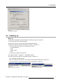


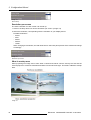

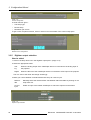
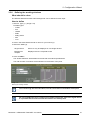
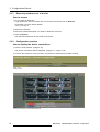

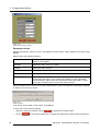
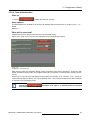


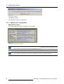


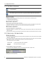

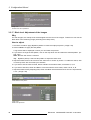

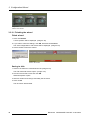
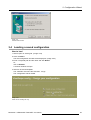
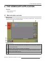

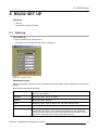


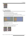


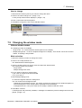
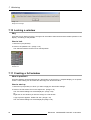
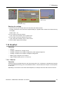

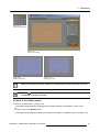
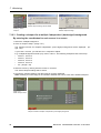
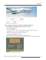
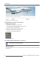
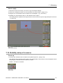

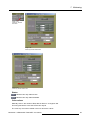
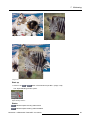
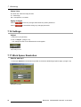
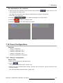
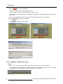
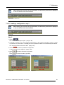


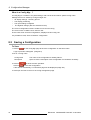
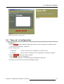
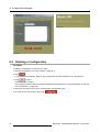
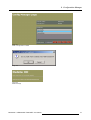
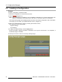
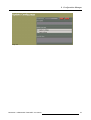

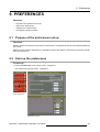
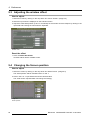
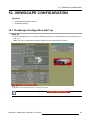


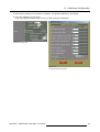
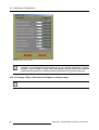
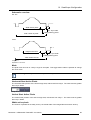

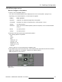
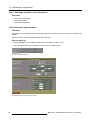
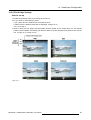
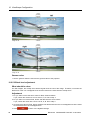

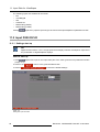


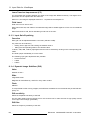
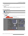


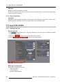


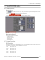


![XLite ToolSet Software [v05]](http://vs1.manualzilla.com/store/data/006304861_1-6990b54c95ba147b0c6f68f733c5e98d-150x150.png)