1
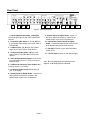
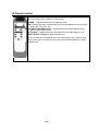
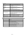
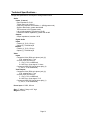
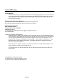
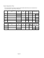
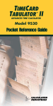
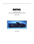
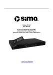
5 Input A/V Switcher with Component Video, Digital Audio, Automatic Input Mode and Volume Stabilizer Model VS-502 User Manual Online Product Registration http://www.simacorp.com Package Contents: 1 - VS-502 A/V Switcher Unit 1 - Power Adapter, (120VAC input, 15VDC output) 1 - IR Remote Control, with Batteries 1 - Instruction Manual Caution: IMPORTANT SAFEGUARDS FOR AUDIO PRODUCTS. PLEASE READ CAREFULLY THE FOLLOWING IMPORTANT SAFEGUARDS THAT ARE APPLICABLE TO YOUR EQUIPMENT 1. Read instructions - All the safety and operating instructions should be read before the appliance is operated. 2. Retain instructions - The safety and operating instructions should be retained for future reference. 3. Heed Warnings - All warnings on the appliance and in the operating instructions should be adhered to. 4. Follow instructions - Follow all operating and use instructions. 5. Water and Moisture - the appliance should not be used near water - for example: near a bathtub, washbowl, kitchen sink, laundry tub, in a wet basement or near a swimming pool. 6. Ventilation - The appliance should be located so that its location or position does not interfere with proper ventilation. For example: the appliance should not be situated on a bed, sofa, rug or similar surface that may block the ventilation openings. 7. Heat - the appliance should be situated away from heat sources such as radiators, registers, stoves or other heat-producing appliances. 8. Power sources - the appliance should be connected to a power supply only of the type described in the operating instructions or as marked on the appliance. 9. Grounding or polarization. - Precautions should be taken so that the polarization or grounding means of the appliance is not defeated. Caution: To prevent electric shock, match the wide blade of this plug to the wide slot, fully insert. Do not use this polarized plug with an extension cord, receptacle or other outlet unless the blades can be fully inserted to prevent blade exposure. 10. Power cord Protection - Power supply cords should be routed so they are not likely to be walked on or pinched by items placed upon or against them, paying particular attention to cords at plugs, convenience receptacles, and where they exit from the appliance. 11. Cleaning - Wipe unit with a damp cloth occasionally to keep it looking new. Do not use harsh chemicals, cleaning solvents or strong detergents. 12. Nonuse periods - The power cord of the appliance should be unplugged from the outlet when left unused for a long period of time. 13. Object and Liquid entry - Care should be taken so that objects do not fall and liquids are not spilled into the enclosure through openings. 14. Damage requiring service - The appliance should be serviced by qualified personnel when: the power cord has been damaged, objects have fallen or liquids spilled into the appliance, the appliance has been exposed to rain, does not appear to operate normally or exhibits a marked change in performance or the unit has been dropped or the enclosure damaged. 15. Service - The user should not attempt to service the appliance beyond that described in the operating manual. All other servicing should be referred to qualified service personnel. Notice to Users The system may cause interference to a TV or radio even when it is operating properly. To determine whether the system is causing the interference, turn it off. If the interference goes away, the system is causing the interference. NOTE: This equipment has been tested and found to comply with the limits for a class B digital device, pursuant to part 15 of the FCC Rules. These limits are designed to provide reasonable protection against harmful interference in a residential installation. This equipment generates, uses, and can radiate radio frequency energy and, if not installed and used in accordance with the instructions, may cause harmful interference to radio communications. However, there is no guarantee that interference will not occur in a particular installation. If this equipment does cause harmful interference to radio or television reception, which can be deter-mined by turning the equipment off and on, the user is encouraged to try to correct the interference by one or more of the following measures: • Reorient or relocate the receiving antenna. • Increase the separation between the equipment and receiver. • Connect the equipment into an outlet on a circuit different from that to which the receiver is needed. • Contact your dealer for help. This device complies with part 15 of the FCC Rules. Operation is subject to the following two Conditions: 1. This device may not cause harmful interference. 2. This device must accept any interference received, including interference that may cause undesired operation. Warning: Changes or modifications to this unit not expressly approved by the party responsible for compliance could void the user’s authority to operate the equipment ©2005 by Sima Products Corp. All rights reserved. No part of this publication may be reproduced or transmitted in any form or by any means without prior written permission from Sima Products Corp. CAUTION: ...........................................................................................2 Table of Contents INTRODUCTION................................................................................4 PACKAGE CONTENTS: ...................................................................1 Page 2 FRONT PANEL................................................................................... 5 REAR PANEL ..................................................................................... 6 IR REMOTE CONTROL................................................................... 7 TYPICAL HOOK UP ......................................................................... 8 OPERATION ..................................................................................... 11 POWER.............................................................................................. 11 INPUTS .............................................................................................. 11 AUTO INPUT MODE........................................................................... 11 VOLUME STABILIZER ACTIVE ........................................................... 11 VOLUME STABILIZATION ADJUSTMENT ............................................ 12 HOW IT WORKS ............................................................................. 13 SIMPLIFIED BLOCK DIAGRAM ........................................................... 13 AUTOMATIC INPUT SENSING............................................................. 13 VOLUME STABILIZATION .................................................................. 14 VOLUME STABILIZER INPUT / OUTPUT CURVES ................................ 14 VIDEO CONVERSION ......................................................................... 15 DIGITAL AUDIO CONVERSION .......................................................... 15 RS-232C INTERFACE ..................................................................... 16 RS-232C CONNECTION .................................................................... 16 VIDEO COMMANDS....................................................................... 17 ADVANCED SYSTEM COMMANDS............................................ 19 ADVANCED DIGITAL AUDIO MAPPING ............................................. 19 FACTORY SYSTEM SETTINGS RESTORE............................................. 19 TERMS ............................................................................................... 20 TECHNICAL SPECIFICATIONS -................................................ 21 LIMITED WARRANTY................................................................... 22 System Organization Chart.......................................................... 24 Page 3 Introduction Congratulations on purchasing Sima’s Model VS502, 5 Input Audio / Video Switcher with Automatic Input Mode (Auto Input) and Volume Stabilization. It has been designed for use with Home Theater, DSS Satellite, DVD, HDTV, Video Games, Audio Recording Equipment, as well as for background music applications. The VS-502 has the following features: • High Bandwidth- low noise audio / video switching for today’s high quality systems. • Five A/V Inputs plus component video and digital audio to allow you to add more A/V sources such as DVD, satellite dish, VCR, HDTV, games, and more to your TV and home theater system. • Convenient Front Panel - A/V input for connecting camcorder or portable video player. • Video Signal Conversion - Simplifies connections and cable hook-up. Up Converts Composite video to S-Video, and S-Video to Component. Down-Converts S-Video to Composite. Page 4 • Digital Audio Conversion - Simplifies your hook-up by providing outputs for both coaxial and optical (Toslink™) audio signals regardless of the source. • Automatic Input Mode (Auto Input) detects and switches to the most recent active input without manual selection. Simply turn on your DVD and the VS-502 directs the video and audio from this device automatically to the TV and audio receiver. • Volume Stabilization - Maintains constant audio volume levels for late night viewing or when channel surfing. It can also be adjusted to add impact to older movies by increasing the dynamic range. • IR Remote control to select a different input or mode. • Brightness Control - Front panel display allows you to dim the lights for nighttime use (via the remote only). • RS-232C Interface to allow the VS-502 to be controlled by home automation equipment or a PC. (Cable not included) • NTSC and PAL Compatible Front Panel 1 2 3 5 4 6 7 Figure 1, VS-502 front panel Controls 1 - Power / Standby - Press to toggle the unit between modes. The red Standby indicator above the button will be lit when the unit is in Standby Mode. 5 - Volume Stabilizer Active - Press to turn Volume Stabilizer on or off. The amber indicator light will be lit next to the selected adjustment level. Indicator light is off when the Volume Stabilizer is bypassed. 2 - Auto Input Mode - Press to turn the Auto Input mode on or off. When on, the unit will scan the video inputs and automatically turn on and switch to the most recent input device turned on. 6 - Volume Stabilizer Knob - This controls the amount of dynamic range you want from 10:1 (compressed – constant audio) to 1:1 setting, (no effect) to 1:2 (expanded – increased dynamic range). 3 - Inputs 1 through 5 - Press to select the desired input to send to the outputs. The green LED indicator will light to show the currently selected input. 4 - IR Receive Window Page 5 7* - Input Jacks – Input # 5 *Note: These jacks cannot be used if input #5 on the back panel is connected. Rear Panel 1 2 3 4 5 6 7 8 9 10 11 12 Figure 2, VS-502 rear panel 1 - Left and Right Audio Inputs, 1 through 5 from the audio output of your VCR, DSS or DVD devices. 9 - Coaxial Inputs for Digital Audio - Inputs 1, 3, & 5 have coaxial connectors to connect to the coaxial output of your DVD, CD player etc. 2 - Composite Video Inputs; 1, 2, 3, 4, & 5 from the composite video output of your VCR, DSS or DVD devices. 10 – Optical and Coaxial Output for Digital Audio - Connect the digital output of the VS-502 to the digital audio input of stereo receiver. 3 - S-Video Inputs; 1, 2, & 5 from the S-Video output of your VCR, DSS or DVD devices. 4 - Component Video Inputs; 3 & 4 from the video output of your Cable Box, DSS or DVD devices. 5 - Left and Right Audio Outputs that connect to the audio inputs on your TV, VCR or surround sound receiver. 6 - S-Video and Composite Video Outputs that connects to your TV or monitor. 7 - Component Video Output that connects to your TV or monitor. 8 - Optical Inputs for Digital Audio – Inputs 2 & 4 have TosLink connectors to connect to the optical output of your DVD, CD player etc. Page 6 11 – RS-232C Connect to your home automation system or PC. 12 – 15V DC Input from the AC wall power supply Note: The rear panel inputs #5 can not be used if input #5 on the front panel are connected. IR Remote Control The IR remote control allows you to control all of the functions available from the unit’s front panel, with the addition of a DIM setting. POWER – Toggles between Active and Standby mode. DIM - Pressing this button cycles through four levels of brightness on the front panel lights-100%, 75%, 50%, 10%. VOLUME STABILIZER ACTIVE - Toggles between the Volume Stabilizer being Active or in the Bypass mode. AUTO SCAN - Toggles between the Auto Input Selection mode being on or off. INPUT SELECT 1 through 5 - Selects desired input. Be sure to install the two AAA batteries in the remote before using. Slide the cover open on the remote in the direction of the arrow and install the batteries as shown inside the unit. Fig. 3 Page 7 Typical Hook up Step 1 Connect the AC adapter to 120 VAC and plug the DC cord into the 15 VDC input on the rear of the VS502. Step 2 You will need to determine how you want to use your system. We have provided two sample hook-up diagrams to help you determine how to connect the components of your system. You can use the last page of this manual as an organizer for your equipment. Read the following notes before installing the VS-502 into your system. Note: The VS-502 does not convert analog audio to digital audio or vice versa. If you have a combination of standard composite video (RCA type jacks) and S-Video (mini-din jacks) on your equipment you can only feed one or both cables to any given input of the VS-502. Option 1: For ease of use, the VS-502 has a composite to S-Video converter. You can feed a combination of composite and S-Video to the VS-502 and feed only a S-Video signal to your TV. This lets you use just one S-Video input on your TV and all sources will automatically be displayed there. Option 2: Additionally, the VS-502 has a S-Video to composite converter. You can feed a combination of composite and S-Video to the VS-502 and feed only a composite signal to your TV. This lets you use just one composite input on your TV and all sources will automatically be displayed there. Option 3: The VS-502 has a composite to component converter. You can feed a combination of composite, s-video and component to the VS-502 and feed only a component signal to your TV. This lets you use just one component input on your TV and all sources will automatically be displayed there. Page 8 Fig. 5 - Basic Hook-up #1: Connecting Two Sources Below shows a hook-up with only two input sources. This shows only inputs 3 and 5 being used. The output A from the VS-502 goes to the TV. Note below how component input 3 is being used a composite video input. Video inputs 3 and 4 can both be used as composite or component video inputs. Figure 5, Hook-up in typical system This would be a typical configuration if you want to watch video and listen to audio on your TV. Note: Remember to always connect the outputs on your VCR/DSS/DVD/etc… to the inputs on the VS-502. Likewise, connect the outputs on the VS-502 to the inputs on the TV/VCR/Receiver/etc… Note: If you have one or more devices which are not stereo and have a single audio output, you have two options. 1) Use a “Y” adapter (available from any electronics store) to split the mono signal into two signals to feed both the Left and Right inputs on the VS-502. 2) Use just the left connector for the audio of that source. Page 9 Fig. 6 - Basic Hook-up #2: Connecting Different Video Types Below shows a hook-up with 3 input sources. Below shows inputs 1, 2 and 3 being used. Input 1 is being used as a composite video input with stereo left and right audio. Input 2 shows how to connect S-Video while using the optical digital audio input. Input 3 unlike (figure 5) is now being used as a component video input along with a coaxial digital audio connection. The VS-502 component output goes to the TV monitor along with the left and right stereo audio. The digital audio goes to the stereo receiver. Input 1 and 2 are being upconverted from composite and S-Video to component video. Figure 6, VS-502 Notes: Remember to select the A/V or AUX input on the TV. Is does not convert the digital signal to analog L+R signals or vise versa. This device will convert optical to coaxial and vice versa. Page 10 Operation When AC power is first applied, all outputs will be muted and all the lights will come on for three seconds and then go out. The Power / Stand-by light will be lit dim red. The Auto Input and Volume Stabilization modes will be active as default. When the unit detects an active video input (composite, SVideo, or component video), the Power / Standby light will turn off and the active input will be selected. Power As long as AC power is not lost, the previous status (last selected input, Volume Stabilizer mode and AUTO SELECT status) will be resumed when Power / Stand-by is pushed. If AC power was lost, the unit will default with input #1 selected, Volume Stabilization on and Auto Input on. Inputs Pushing a input button on either the front panel or on the IR remote will cause the current input and associated LED to go off and the new input to come on. Auto Input Mode If the Auto Input mode is on, as a new input becomes active, the VS-502 will automatically change to the new input. If you want to go to another A/V source, simply select the input using the front panel button or the remote. If you don’t want the VS-502 to automatically select an active input, turn the Auto Input mode off. Please note when you activate Auto Input mode, it scans the inputs when the VS-502 is on or in the stand-by mode. A new input becoming active will cause the unit to wake from standby, and select the new input. When the unit is in the standby mode, the Power/Standby light will be dim and all other lights will be off. When a video device is turned on, like a VCR on Input #1, the Power/Standby LED will turn off; the input corresponding to the device will turn on, along with the Auto Select LED. If a second device is turned on (say the DVD player on input #2) the # 2 light will illuminate and it will be selected and fed to your TV. If the second device is turned off, after about 5 seconds, input #1 will be selected. If both devices are turned off, after about one minute, the VS-502 will turn off and go into standby mode waiting for an input. Note: If an input goes off and back on in less than 5 seconds, the VS-502 will not sense the input change so no input change may occur, to avoid flicker. Volume Stabilizer Active (Only on analog audio – no effect on digital audio) If the Volume Stabilizer Active light is on, then the output of the audio switcher will be routed through the Volume Stabilizer circuitry. When the Volume Stabilizer Active light is off, the audio signal is bypassed and the Volume Stabilization setting will not have any affect on the audio signal. Page 11 Volume Stabilization Adjustment Volume Stabilization lets you control the dynamic range of the audio signal to accommodate your needs. The Volume Stabilizer light must be on for this to function. The numbers show the ratio of the input signal to the output signal in dB. Thus, the setting in the middle (1:1) means that the input signal is the same as the output signal. Likewise, if you set Volume Stabilization to the 10:1 setting, it means that a 10-dB change in the input volume level will result in only a 1-dB change in the output level. This will tend to keep the volume constant even when the sound changes from soft to loud and back to soft. Setting 10:1 2:1 1.3:1 1:1 1:1.3 1:1.7 1:2 Description Use Maximum compression maintains constant volume level by compressing dynamic range Modest compression Slight compression Normal volume fluctuations Slight expansion Moderate expansion Maximum expansion increases dynamic range Watching movies late at night Background music Making tapes for airplane use Making tapes for automotive use Minimal audio compression Just like bypass (VS off) Adds some impact to audio sources Adds moderate impact to audio sources Restores dynamics to old recordings Reduces hiss and noise below noise “floor” Can “un-do” compression on tapes made with 2:1 compression Hint: If you want the minimal volume changes when changing sources, changing channels or watching a movie, be sure the Volume Stabilization is set to the 10:1 position and the VS ACTIVE light is on. Note: It is normal to notice volume variations even with the VS-502 set to the 10:1 setting. This is due to the fact the human ear is more sensitive to certain frequencies and these will tend to sound louder. Some commercials on TV have been modified to sound louder than the normal program. Although the VS-502 will not eliminate all of these volume fluctuations with these types of commercials; it will help a great deal to keep the volume level constant. Caution: Very loud sound levels can result when using the 1:2 expansion mode. Keep your volume levels low to avoid damage to speakers or amplifiers. Page 12 How it Works This section has more technical information for the person who wants to learn more about the VS502. In the block diagram below you can see how the audio and video inputs are selected and fed to the output buffer amplifiers (Only the left audio channel is shown). Notice how the Volume Stabilizer Active switch allows you to bypass the Volume Stabilizer circuitry. The diagram also shows how the selected video (composite, S-Video, or component) signal is fed to the output buffer amplifiers and into the converter which then feeds all of the outputs. Simplified Block Diagram Automatic Input Sensing When the Auto Input mode is on, the VS-502 constantly scans the video inputs, Composite, S-Video, and Component waiting for a video input. When you turn on a device (VCR, DSS, etc.) a microprocessor in the VS-502 senses the video input, turns on the VS-502 (when it is in the stand-by mode) and selects the input. If a second input occurs, the unit will switch to the new input. If the second input is turned off, Page 13 in approximately 5 seconds, the unit will go back to the first input. If the first input goes off, the unit will turn itself off and return to the stand-by mode in about one-minute and wait for an input to become active. Note: The Automatic Input Sensing only senses the video signals and not the audio signals. Volume Stabilization The VS-502 monitors the active audio source and depending upon the setting of the Volume Stabilization adjustment, constantly changes the volume level smoothly to compensate to input volume level changes. Let’s say the unit is set to the 10:1 setting. When the input level increases by 10 dB, that is it gets louder, in just a few milliseconds, the VS-502 reduces the volume by 9 dB so the output only changes by about 1 dB. Likewise, if the audio signal gets softer by 10 dB, the VS-502 adds gain to the signal so it is only reduced by about 1 dB. This way, the unit automatically brings up soft dialogue when watching movies. The diagram below shows the relationship between an input audio signal and the output audio signal. Normal output level for most consumer equipment is about -10 dBV (approximately 250 mV RMS). This is why all the curves intersect at the -10 dBV point. Looking at the 1:1 line, you can see if an input signal is at the -20 dBV level (slightly soft volume wise) it will come out also at -20 dBV. There is no change. If the unit is set for 10:1 compression, the same -20 input will come out at about -11 dBV as shown in the diagram below. This signal is boosted about 9 dB. Likewise, if the input signal goes up to 0 dBV, the output will be -9 dBV. For an input change from 20 dBV to 0 dBV (a 20 dB change) the output only changed 2 dB (-11dBV to -9 dBV). This results in soft conversations being boosted to a normal level and loud special effects being reduced to a normal level. With the VS-502 set to 1:2 expansion, if the input makes the same -20 dBV to 0 dBV change as above, the output now goes from –30dBV to +10 dBV. This is a 40-dB-output change for a 20 dB input change. This results in soft sounds, including tape hiss and soft conversations, becoming even softer and loud special effects becoming even louder. Volume Stabilizer Input / Output Curves Page 14 Video Conversion The VS-502 has special circuitry to convert the composite video inputs to the S-Video outputs and the composite/S-Video signals to component video. Video Input Output Composite Original S-Video No Signal Up Converted Component No Signal Up Converted Video Input Output Composite Down Converted S-Video Original Component Up Converted Video Input Output Composite S-Video Component Original Digital Audio Conversion The VS-502 converts the coaxial and optical digital audio inputs and sends the signal out both the coaxial and optical outputs simultaneously. This lets you connect a single digital audio cable (either optical or coaxial) between the VS-502 and your receiver and feed the VS-502 with both coaxial and optical inputs. Note: It does not convert the digital signal to analog L+R signals or visa versa. Note: The volume stabilizer only works on analog L+R signals and does not work on the coaxial and optical signals. Page 15 RS-232C Interface The RS-232C interface on the VS-502 lets you connect the unit to a home automation system and control the various functions of the unit. Computer (DB-9) RS-232C Connection The specifications of the RS-232 port are: 9600 baud 1 start, 8 bits, no parity No handshaking No Flow Control DB-9, Connector Pin 5 2 3 Function Ground Transmit Receive VS-502 (DB-9) RS232 Command Structure RS232 commands sent to the VS-502 consist of five bytes: a start character, an address character, a command mode character, a sub-command character and a command data byte. There is no need to send a carriage return or line feed at the end of the message. If these characters are sent, they will be ignored. The received message structure is summarized in the following table: Start Character @ Channel Command Sub-Command Data 0= Unit Control Command S = Setup S = Standby 0 = Off 1 = On ? =Next LED brightness step – decreasing N=Video Out NTSC P=Video Out PAL A=Video Out Auto 0 = Off 1 = On 1 – 5 = Channel selection A = Auto Input D= LED Dimmer V=View V = View 1–5 Channels P = Front Panel Buttons E = Every signal ??? = Status Request H=Hue 00 to 63=Range of Hue Control S=Setup G=Gain 0-3=Range of Video Gain Note that not all command / sub-command / data combinations are valid. See figure 8 for a summary of all valid commands. Page 16 Message Acknowledgement Start Character $ Channel Status 0 0 = Message received OK 1 = Error 2 = Data string follows 0 = Message received OK 1 = Error 1-5 Fig.7 The VS-502 will ignore any message that does not begin with the @ character; “01” will be returned. When the VS-502 receives a correctly initiated RS232 message, it will respond with an acknowledgement message, followed by a block of data, as appropriate. The acknowledgement message consists of three bytes (a start character, an address character and a status character). The message structure is summarized in the following table: Valid RS232 Commands: All valid RS232 commands are summarized in the following table. Comman Function d Setup Commands @0SS0 Set standby off (switch VS-502 on) @0SS1 Set standby on (switch VS-502 off) @0SA0 Set Auto Input mode off @0SA1 Set Auto Input mode on @0SD? Cycle LED brightness @0SVN Set the video output to NTSC video format @0SVP Set the video output to PAL video format Set the video output to Auto to select either @0SVA format @0SP0 Set front panel switch lock-out=false @0SP1 Set front panel switch lock-out=true Video Commands @0VEn Set outputs to channel n (channels 1 – 5) Status Commands @0??? Get VS-502 Status Channel Hue and Gain Commands @nHxx Set Channel n (1-5) to Hue (00-63) @nSGx Set Channel n (1-5) to Gain Setting (0-3) Fig.8 Page 17 RS232 Status Response The returned data format (in response to a status request) takes the following format: Message header = $02 as per Figure 7 above (0 = RS232 address). Message data: $02VEXCSXSDXSSXSAXAV=XX SVXCVX No=XX Nv=XX Pt=XX Nt=XX Sv=XX E2X SWX TVX H,G=XX,X XX,X XX,X XX,X XX,X Note that the mnemonics are the same as for the received RS232 commands. Message contents are defined in the following table: Mnemonic VE CS Meaning Currently Selected Channel (all MUXes) Compander Status SS Standby Mode SD SA Dimmer Status Auto Input Mode Status AV,SV,CV,No,Nv,Pt,Nt,Sv,E2,SW,TV H,G Hue and Gain Setting for Each Channel Data 1 - 5 = Channel Number 0 = Off 1 = On 0 = Off 1 = On 1 - 4 (1 = Min Level) 0 = Off 1 = On Internal Sima Repair Diagnostics Factory default: 20,1 20,1 20,1 20,1 20,1 IR commands take precedence over front panel key presses. Thus, if an IR command is received at the same time as one of the front panel buttons is pressed, the IR command will be executed and the button press ignored. However, RS232 commands take precedence over both IR and front panel commands, so if an RS232 command is received at the same time as an IR command, the IR command will be ignored. Example: Unit channel: 0 To turn standby mode off: @0SS0 To turn dimmer status down 1 level: @0SD? To lock-out front panel: @0SP1 To set auto input mode on: @0SA1 Page 18 Advanced System Commands Advanced Digital Audio Mapping Some home theater setups may require that the digital audio be mapped from one input to another. For example: Video Input 4 has a Co-axial Digital Audio connection by default. To use a optical digital audio cable with Video Input 4, the digital audio will need to be mapped. To enter into Digital Audio Mapping mode: 1. Disconnect the VS-502 from AC Power 2. While holding the AUTO INPUT MODE, and INPUT 1 buttons, reconnect the AC Power to the VS502 Hold Hold 3. The Input 1 LED will be blinking, to indicate that the unit has entered into Digital Audio Mapping Mode. 4. Press the Digital Audio Input that you would like to map to Video Input 1. (For example, pressing Input 2 at this point would map Digital Audio Input 2, to Video Input 1.) 5. After Video Input 1 has been mapped, Input 2 will begin to blink. At this point the Digital Audio Input can be selected for Video Input 2. 6. After the button is pressed, the unit will continue through Inputs 3,4,5. 7. At the conclusion of programming, all of the lights on the unit will blink 3 times while the memory is being written. 8. Examples: a. Pressing Input 1 five times in a row, would cause Digital Audio Input 1 to be used for Video inputs 1-5 b. Pressing 1,2,3,4,5 would cause the unit to have the factory default Digital Audio mapping. Factory System Settings Restore At any time the VS-502 can be restored to its factory default settings. 1. Disconnect the VS-502 from AC Power 2. While holding the POWER, AUTO INPUT MODE, and INPUT 1 buttons, reconnect the AC Power to the VS-502 Hold Hold Hold 3. All of the lights on the unit will blink 3 times while the unit’s memory is being restored to the factory settings. Page 19 Trouble Shooting Problem Power/Stand-by light does not come on No video output -Composite -S-Video -Component No audio output -Analog -Digital No input is selected Picture is black and white Auto Input does not detect device when turned on Unit goes to standby after one minute. Volume seems to vary too much between sources IR remote does not work Solution Make sure power adapter is plugged into a working outlet. Stand-by light is dim (normal in stand-by mode) Is standby light off? Is input light lit? Make sure correct input is selected. Make sure inputs and outputs are not reversed. Is standby light off? Is input light lit? Make sure correct input is selected. Make sure inputs and outputs are not reversed. Push STANDBY button so unit is in the ON mode. Your TV is using both composite and S-Video inputs. Use only one or the other to feed into the VS-502 or into your TV. Is the video cable connected from the device to the VS-502? Is the device producing a video picture? Some products do not generate a video signal (just a blue screen) unless the tape/DVD/etc. is actually playing. Is Auto Input turned on? Normal if there are no video inputs. Either turn video input on or turn Auto Input off. Make sure Volume Stabilization is active. Set Volume Stabilization to the 10:1 setting. Replace batteries in remote. Terms Term Component Video Composite Video Compression dB dBV Expansion S-Video Definition High quality video using 3 cables (Y, Pb, Pr) used with DVDs, DTV and HDTV Standard video signal using RCA style jacks Reduce the dynamic range of an audio signal by decreasing loud signals and increasing soft signals. Short for decibels - Measure of relative sound levels. The smaller change a human ear can hear is about 1 db. Measure of absolute voltages. 0 dBV is equal to .775 v rms. Most consumer equipment operates at about -10 dBV. Increase the dynamic range of an audio signal by increasing loud signals and decreasing soft signals Video signal that separates the color signal from the brightness signal and uses mini DIN connectors. Page 20 Technical Specifications Design and specifications are subject to change without notice Audio Inputs, (5 stereo) Input impedance, 47 KΩ Typical input level, 300 mV Frequency response 20 to 20KHz, +/- 3dB (bypass mode) Signal to Noise ratio, greater than 80 dB THD less than 0.03% (bypass mode) Left to right separation, greater than 60 dB Channel to channel separation, greater than 60 dB Outputs Output Impedance, less than 150 Ω Digital Audio Inputs Coaxial (3), 75 Ω, 0.5V p-p Optical (2), TOSLINK style Outputs Coaxial (1), 75 Ω, 0.5V p-p Optical (1), TOSLINK style Video Inputs Composite Video (RCA style phono jack) (5) 75 Ω, unbalanced, 1 V p-p S-Video (4 pin mini DIN) (3) Y: 1 V p-p, 75 Ω, unbalanced C: 0.286 V p-p, burst signal, 75 ohms Component Video (RCA style phono jack) (2) (Y, Pb, Pr, 75 Ω unbalanced) View Outputs Composite Video (RCA style phono jack) (2) 75 Ω, unbalanced, 1 V p-p S-Video (4 pin mini DIN) (2) Y: 1 V p-p, 75 Ω, unbalanced C: 0.286 V p-p, burst signal, 75 Ω Component Video (RCA style phono jack) (1) (Y, Pb, Pr; 75 Ω unbalanced) Power Input: 15 VDC, 500 ma Size: 17” wide x 8” deep x 2.5” high Weight: 5.875 lbs Page 21 Limited Warranty Limited Warranty Sima Products Corp. (“Company”) warrants that is the accompanying product proves to be defective to the original purchaser in material or workmanship within 90 days from the original retail purchase, the Company will, at the Company’s option, either repair or replace same without charge (but no cash refund will be made). What you must do to enforce Warranty You must deliver, mail or ship the product, together with the original bill of sale, this limited Warranty statement as proof of warranty coverage to: Sima Products Corporation Attn: Customer Service 140 Pennsylvania Ave., Bldg. #5, Oakmont, PA 15139 To receive special offers and discounts, register your product online at www.simacorp.com Limitation of Liability and Remedies Sima shall have no liability for any damages due to lost profits, loss of use or anticipated benefits, or other incidental, consequential, special or punitive damages arising from the use of, or the inability to use, this product, whether arising out of contract, negligence, tort or under any warranty, even if Sima has been advised of the possibility of such damages. Sima’s liability for damages in no event shall exceed the amount paid for this product. Sima neither assumes nor authorizes anyone to assume for it any other liabilities. Some states do not allow the exclusion or limitation of incidental or consequential damages, so the above limitation or exclusion may not apply to you. This warranty gives you specific legal rights, and you may also have other rights, which vary from state to state. Copyright 2005 © Sima Products Corp. 140 Pennsylvania Ave. Bldg #5 Oakmont, PA 15139 www.simacorp.com 800-345-7462 PN# 21731 Page 22 Sima Products Corp. 140 Pennsylvania Avenue, Building #5 Oakmont, PA 15139 USA www.simacorp.com Visit us at www.simacorp.com E-mail us at [email protected] Manual # 21731 Page 23 System Organization Chart Fill in the chart below to help you organize and remember what devices are connected to the inputs and outputs. Save for future reference. Inputs From (VCR, DSS, etc.) Component Video Composite Video SVideo L&R (analog) audio Digital audio Coaxial/Optical To (TV, Receiver, etc.) Component Video Composite Video SVideo L&R audio (analog) Digital audio Coaxial/Optical #1 #2 #3 #4 #5 Outputs View A View B Page 24