1
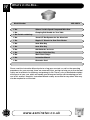
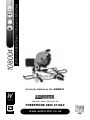
250mm Variable Speed
Compound Mitre Saw
Axminster Reference No: AWMS10
w w w. a x m i n s t e r. c o . u k
108004
User Manual
2005
W
AXMINSTER
W H I T E
Index of Contents...
Page No.
Index of Contents................................................................................................................... 02
Declaration of Conformity………….………........……..…………........................................03
What’s in the Box………….………........……..…………..........................................................04
General Instructions for 230v Machines................................................. 05-06-07-08
Initial Setup.........................................................................................................08-09
Specifications….………........……..…………........................................................................10
Identification & Description of the Mitre Saw........................................... 10-12-14-15
Illustration and Parts Description ......................................................................11-13-15
Setting Up the Machine................................................................................ 16-17-18
Setting the Laser.................................................................................................19-20
Table of Capacities..................................................................................................21
Changing the Saw Blade................................................................................... 22-23
Illustrated Parts Breakdown for the Mitre Saw.......................................................24
Maintenance.............................................................................................................25
Notes...................................................................................................................26-27
Saf
sp irator
Re
Sa
Two
E
R
Ey
y Helm
fet
Safety Protection Symbols
r
fety Viso
Sa
et
st Mask
Du
F ootw
ety
r
ea
tiv e Glo
tec
s
ve
Def ende
rs
ar
bly
m
n Asse
Ma
ro tectio
eP
n
AXMINSTER
W H I T E
al
W
d Manu
ea
Pro
!
The symbols shown on the cover of this
manual advise that you wear the correct
safety protection when using this machine.
SAFETY!!
Declaration of Conformity...
W
AXMINSTER
W H I T E
Copied from CE Certificate
The undersigned, K. Bodenstein authorised
by Zhangjiagang MFG Co., Ltd.
No. 8 Haifeng Road, Nan Feng Town
Zhangjiagang, Jiangsu 215628
P.R. China
declares that this product:
MIS-250E-2 Mitre Saw
manufactured by Zhangjiagang MFG Co. is in compliance
with the following standards or standardisation documents
in accordance with Council Directives
EN 50366: 2003
FREEPHONE 0800 371822
03
W
What’s in the Box...
AXMINSTER
W H I T E
Model Number:
MIS 250E-2
1 No.
250mm Variable Speed Compound Mitre Saw
1 No.
Clamping Bolt Handle for Turn Table
1 No. Packet containing:1 No.
13mm A/F Box Spanner for the Arbor bolt
1 No.
Nippled 'Y' Wrench for Saw Plate Washer
1 No.
5mm Allen Key
1 No.
6mm Allen Key
2 No.
AAA Batteries for Laser
1 No.
Saw Dust Collection Bag
2 No.
Work Piece Clamps
1 No.
Instruction Manual
1 No.
Guarantee Card
Please read the Instruction Manual prior to using your new tool; as well as the operating
procedures for your new tool, there are numerous hints and tips to help you to use the tool
safely and to maintain its efficiency and prolong its life. There is also a detailed description
of the parts of your saw, which will enable you to become familiar with terminology we will
use in this manual. Keep this Instruction Manual readily accessible for any others who may
also be required to use the tool.
04
www.axminster.co.uk
General Instructions for 230v Machines...
W
AXMINSTER
W H I T E
Good Working Practices/Safety
The following suggestions will enable you to observe good working
practices, keep yourself and fellow workers safe and maintain your
tools and equipment in good working order.
!
WARNING!!
KEEP TOOLS AND EQUIPMENT OUT
OF THE REACH OF YOUNG CHILDREN
General Advice
If you are totally unfamiliar with the use of a power saw, please seek at least a minimum of
tuition and advice from an informed, qualified source. An amateur woodworker or hobbyist
just starting out is advised to undertake a short course on the use of woodworking
machines run by a professional woodworker. These are often offered by your local authority,
as evening classes., etc.
Mains Powered Tools
Primary Precautions
These tools are double insulated and supplied with a 13 Amp. Plug and 2 core power cable.
Before using the tool inspect the cable and the plug to make sure that neither are damaged.
If any damage is visible have the tool inspected/repaired by a suitably qualified person. If it
is necessary to replace the plug, it is preferable to use an 'unbreakable' type that will resist
damage on site. Only use a 13 Amp plug, make sure the cable clamp is tightened securely.
Fuse at 13 Amp. It is also recommended that a switched power outlet is used. If extension
leads are to be used, carry out the same safety checks on them, and ensure that they are
correctly rated to safely supply the current that is required for your machine.
Work Place/Environment
Always carry the machine with the saw locked in the housed (down) position. Pre-mounting
the saw on a sub frame (a suitable piece of plywood/blockboard) with sufficient margin to
allow the whole to be clamped onto a stable work surface, increases the speed with which
the saw can be brought into operation. However the saw is mounted, make sure that it is
clamped/screwed down to a stable, flat surface before commencing operations.
The machine is designed for indoor use, do not use when or where it is liable to get wet. If
the machine is set up in the open, and it starts to rain (unusual though this would be in
U.K.), cover it up or move to a dry place. If the machine has gotten wet; dry it off as soon as
possible, with a cloth or paper towel. Do not use 230Va.c. powered machines anywhere
within the site area that is flooded or puddled, and do not trail extension cables across wet
areas. Keep the machine clean; it will enable you to more easily see any damage that may
have occurred. Clean the painted areas of the machine with a damp soapy cloth if needs be,
do not use any solvents or cleaners, as these may cause damage to any plastic parts or to
the electrical components.
Make certain that you have fitted the correct saw blade for the job in hand.
Keep the work area as uncluttered as is practical, this includes personnel
as well as material.
FREEPHONE 0800 371822
05
W
General Instructions for 230v Machines...
AXMINSTER
W H I T E
!
WARNING!!
UNDER NO CIRCUMSTANCES SHOULD
CHILDREN BE ALLOWED IN WORK AREAS
Once the saw is mounted, carry out any setting operations, (mitre, tilt..?),
and remove all tools used in the setting operations (if any) and place safely
out of the way. If you are using long lengths of material arrange for extra
support beyond the boundary of the machine.
It is good practice to leave the machine unplugged until work is about to
commence, also make sure to unplug the machine when it is not in use. Always
disconnect by pulling on the plug body and not the cable.
DO NOT use your hands to hold the work on the machine, use the clamps provided, and
observe the old woodworkers adage of 'never putting your hands closer than one
handbreadth to the cutting tool'. Do not attempt to cut or re-cut short pieces that cannot be
held by the clamp.
Make sure you are comfortable before you start work, balanced, not reaching etc.
If the work you are carrying out is liable to generate flying grit, dust or chips, wear the
appropriate safety clothing, goggles, gloves, masks etc., If the work operation appears to be
excessively noisy, wear ear-defenders. If you wear your hair in a long style, wearing a cap,
safety helmet, hairnet, even a sweatband, will minimise the possibility of your hair being
caught up in the rotating parts of the tool, likewise, consideration should be given to the
removal of rings and wristwatches, if these are liable to be a 'snag' hazard.
DO NOT work with cutting tools of any description if you are tired, your attention is
wandering or you are being subjected to distraction. A deep cut, a lost fingertip or worse, is
not worth it!
DO NOT work with cutting tools if you are taking prescribed medicine, unless you have
confirmed that this medicine will not impair your awareness or your reactions.
DO NOT use the machines within the designated safety areas of flammable liquid stores or
in areas where there may be volatile gases. There are very expensive, very specialised
machines for working in these areas, THIS IS NOT ONE OF THEM.
CHECK that saw blades are undamaged and are kept clean and sharp, this will maintain
their operating performance and lessen the loading on the tool.
Above all, OBSERVE…. make sure you know what is happening around you, and USE
YOUR COMMON SENSE; for no matter how many precautions we list, remember your
safety is ultimately your responsibility.
General Safety Precautions for Compound Mitre Saw
Before using the saw read the instructions thoroughly and make sure you understand them.
Carry out a visual inspection of the saw, checking for damage, or anything untoward, (Do
you know who used it last? That person may be able to confirm that the saw was “fine”
when last used or not, blades need sharpening/replacing etc.
06
www.axminster.co.uk
General Instructions for 230v Machines...
W
AXMINSTER
W H I T E
General Safety Precautions for Compound Mitre Saw (Continued)
DO NOT change blades with power connected. Always use the correct accessories;
especially the correctly sized spanner on the arbor bolt, DO NOT risk damaging the saw by
using incorrectly fitting accessories. If the saw does not have a specific device to lock the
saw shaft, DO NOT jam/wedge the motor fan, it is better to wedge the saw blade with a
piece of scrap timber. After fitting the blade, make sure that all ancillary tools used during
the blade change operation have been stowed away correctly. REMEMBER THE ARBOR
BOLT HAS A LEFT HAND THREAD.
When fitting blades, refer to the manufacturer’s instructions concerning the maximum
capabilities of the saw, i.e. cutting capacities and capabilities in various materials,
observance of these guidelines, and clean, sharp saw blades ensure maximum performance
and optimise the life of your saw.
DO NOT overload the saw. (Try to cut too fast)
CHECK that the blade is fitted correctly, i.e. check that the blade is seated properly, the
arbor bolt is fastened and a manual rotation of the blade does not indicate any wobble.
CHECK that the kerf slot in the saw gullet (and under) is clear. The kerf slot is fully
enclosed, as a safety measure, to protect against the saw teeth protruding through table.
REMEMBER to clean it regularly.
If the saw gullet gets damaged it may not support the work close up to the blade and this
will result in bad breakout. Replace the saw gullet as soon as possible.
CHECK the basic parameters of the saw, viz:- check the blade is vertical to the turn table
when the tilt indicator reads '0'; check the blade is perpendicular to the rear fence when the
turn indicator reads '0'. This will give you confidence that the angles you wish to set on the
saw will be correct. If either of these basic parameters is not met, refer to the specific
section in the Instruction Manual that deals with “Setting up your machine”.
Set the required mitre angle or tilt angle or both, then carry out a “dry” run to ensure that
you will be able to complete the saw cut without any problems. Connect the power, give the
machine a quick “burst” off load and in a safe position to check that everything is correct
before proceeding with the work operation.
Make sure that the stuff is hard against the backfence before starting the saw.
Always allow the saw to run up to speed before attempting to cut.
Pull the saw over in a smooth continuous movement.
We strongly advise that all material is clamped to the table before any sawing is carried out.
When 'fine' cutting e.g. beads, architraves, framing, etc., if the material is still 'breaking out'
at the rear of the cut, you may be able to minimise the damage by the addition of a thin
facing board of an appropriate hardwood, clamped or screwed across the face of the fence
to act as a “spelch”.(Make sure you fasten the board on both sides of the fence and cut the
saw slot before any actual work is done.)
FREEPHONE 0800 371822
07
W
AXMINSTER
W H I T E
General Instructions for 230v Machines...
General Safety Precautions for Compound Mitre Saw (Continued)
When you have finished the cut, allow the saw to rise to its 'up' position, check that the
lower guard has returned to cover the saw blade. Allow the blade to come to a stop before
removing the workpiece.
When working with timber than is bent, bowed, in wind, cupped, etc., make sure that the
offending timber is placed to the machine such that the cut will not allow the timber to 'fall'
to the table or fence and pinch the saw blade.
DO NOT allow the saw to 'stall'; if unfortunate circumstances cause the machine to stall,
switch off immediately, disconnect the machine and clear the 'jam' by hand.
DO NOT attempt to re-start the machine until the 'jam' is cleared. If it was a severe 'jam' that
required much heaving and knocking to clear, check the basic parameters of the machine
before reconnecting the supply and re-commencing operations.
Laser Radiation
This machine is equipped with a Class 2 laser device. The laser must not
be replaced with any other type. The emitted radiation is not harmful in
anyway. You must not modify the laser unit in any way.
WARNING: DO NOT look directly into the laser beam or into the opening
from which the beam is emitted. NEVER allow the beam to strike reflective
Power output<1mW
surfaces, or be reflected into the eyes of people or animals. Even short
visual contacts can cause optical damage.
Remove the batteries from the battery case if the saw is to be out of use for any lengthy
period.
Class 2 Laser
Initial Setup...
Remove the stowed items from the free side packaging block, i.e. the dust bag, support
bars etc., (the other packing block is fitted around the motor). Remove the free side packing
block and then lift the saw clear of the box and set it on a clear flat surface, taking care not
to trap or pinch the power cable under the chassis. Remove the packing block from around
the motor. Press the saw body down and pull the lockdown knob out to allow the saw to
rise. Remove the protective paper from the table. The machine is covered in a protective
coating and will need to be thoroughly cleaned. Use a proprietary de-greasing agent or
paraffin et al. Unfortunately, this cleaning process is always a bit 'mucky' especially if you
tackle the job with a high level of enthusiasm. You are advised to wear overalls or coveralls
etc, during the process.
After cleaning, especially if you used paraffin, dry all surfaces and possibly, lightly coat the
exposed metal surfaces to prevent any rusting. Bear in mind the stuff you will be cutting and
its possible finishing process when you choose your anti-corrosion agent.
Screw the Clamping handle bolt through the positioning arm of the turn table assembly
(See Fig 1). Attach the sawdust collection bag to the Dust extraction duct at the rear of the
machine (See Fig 2)
08
www.axminster.co.uk
Initial Setup...
If required at this stage, insert the work support rails (remember to insert right through to
the support brackets (See Fig 3). Clamp in position using the star head clamping bolts
(See Figs 4 & 4a). Extend the rear support bracket.
W
AXMINSTER
W H I T E
Well done, one mitre saw 'ready to go' .
Having unpacked your saw and its accessories please dispose of any unwanted packaging
properly. A lot of the packaging is biodegradable.
Clamping handle
Fig 1
Fig 2
Saw dust
collection bag
Positioning arm
Screw the clamping handle
bolt into the positioning arm
Attach the sawdust collection
bag to the dust extraction duct
Fig 4
Support
bracket
Star head clamping bolt
clamped to the support rail
Work support rail
Fig 4a
Fig 3
Rear support bracket
Star head clamping bolt
FREEPHONE 0800 371822
09
W
Specification...
AXMINSTER
W H I T E
Axminster No.
AWMS10 (108004)
Blade size.
250mm x 16mm Bore
Motor
230V 50Hz 1400W
Speed
SOFT START
Max Mitre Angle
Left
Table presets
1800- 4500 rpm
47˚
Right
47˚
Left and Right 15˚, 22.5˚, 30˚ and 45˚
Max Tilt Angle
Vertical to Left 45˚
Table Size
450mm x 140mm
Dust Extraction Port
48mm Diameter
Weight
14.5 Kgs
Maximum footprint, Saw 'up', sawdust bag and support rails fitted.
Width 830 Depth 810 Height 510
Minimum footprint, Saw 'housed', no accessories fitted.
Width 450 Depth 480 Height 320
Supplied Cable Length
2 Metres
Laser Aligning Device.
Class 2 Protection
Noise measurements to EN 50144
Lpa (sound pressure)
dB(A) 96.5
Lwa (acoustic power)
dB(A) 109.5
1.3 M/s2
Vibration
!
IT IS RECOMMENDED THAT YOU WEAR EAR
PROTECTION WHEN USING THIS DEVICE
Identification & Description of the Mitre Saw...
Your 10” compound mitre saw should have been shipped to you in the 'housed' position, i.e.
with the saw body locked down. Please take some time to identify the various parts of your
machine so that you familiar with the terminology we will use to enable you to set up and
operate your machine safely and correctly.
Lock down pin
10
The Lock Down Pin is a simple latching pin that can be engaged
(pushed to the left) into the saw mounting frame to hold the saw body
down in the 'housed' position or disengaged (pulled to the right) to allow
the saw body to rise to the 'up' position. Push down on the saw to ease
the friction on the pin before unlatching. DO NOT engage the Lock Down
Pin whilst operating the saw.
www.axminster.co.uk
Illustration & Parts Description...
W
AXMINSTER
W H I T E
Interlock lever
Operating handle
Upper guard
Front fixed lower guard
Sawdust collecting bag
Pivoting lower guard
Kerf plate
Fence
Clamping bolt handle
Rear fixed
lower guard
Laser
Turn table
Sprung locating
thumb lever
Support rail
Preset notches
Work piece clamp
Index pointer
Turn scale
Turn table positioning handle
and clamp
FREEPHONE 0800 371822
11
W
AXMINSTER
W H I T E
12
Identification & Description of the Mitre Saw...
Operating
Handle
The operating handle contains the trigger switch and is the handle used
to pull the saw over into the work.
Trigger switch
Housed in the handle of the Operating handle the Trigger Switch is a
good width switch that can be easily 'squeeze' operated whilst pulling
the saw over into the work. The whole hand is used to grip both the
operating handle and the switch simultaneously. Incorporated into the
trigger switch and speed control circuitry is a soft start function which
allows the blade to run up to speed, over a timed period, thus reducing
the 'snatch' effect on the gear train, and increasing the longevity of the
machine.
Upper guard
Fixed guard, part of the saw body frame, covering the top part of the
saw blade.
Rear fixed
lower guard
The fixed lower guard is a wide plate, bent into a 'U' section. The saddle
of the 'U' is bolted to the saw body frame, with the 'arms' of the 'U'
extending on either side of the blade covering the saw teeth while the
saw is in the 'up' position.
Pivoting
lower guard
The Pivoting lower guard is a 'trough' guard that covers the lower front
portion of the saw blade. It is pivoted on a mounting on the Upper Guard
and is operated by a lever that rotates it out of the cutting line when the
saw is 'pulled over'. The guard has an interlock fitted to prevent the saw
being 'pulled over' inadvertently. A conscious action, in this case
'thumbing' the interlock lever aside, is required to enable the saw to be
used.
Front fixed
lower guard
A small shaped plastic extrusion mounted on the upper guard that
covers the front lower section of the saw blade as a safety measure,
preventing access to the front edge of the saw when the lower pivoting
guard is rotated out of the cutting line.
Interlock lever
A small moulded 'L' shaped extrusion that is sprung loaded to engage
with front lower section of the rotating guard. It needs to be moved out
of the path of the front lower guard section to allow the guard to rotate
out of the cutting line of the saw.
Main saw
chassis
Aluminium casting that mounts all the other pieces of the mitre saw. It
has 4 moulded feet that are bored to allow fixing screws or bolts to be
inserted to secure the saw to a stable work surface or a 'quick mounting'
board. The front edge of the casting has a relieved terrace that has the
'turn' scale (50˚ left to 50˚ right) raised in bas relief. Below the front
apron of the casting are a series of castellated notches that allow the
turn table positioning handle to pre-locate at various angles. Through the
sides of the casting are the holes for inserting the extended work
support rails. There is a further extruded land beyond the entrance
holes, on the underside of the chassis that are the stabilising locations
for the end of the support rails. The front of the chassis has two drilled
and tapped holes that run through the support rail housings and take the
small star headed bolts used to clamp the support rails in position. On
the front of the chassis proper are two square extrusions, bored through
to allow the mounting of the work piece clamps.
Illustration & Parts Description...
W
AXMINSTER
W H I T E
Preset speed
selector
Power cable
Trigger switch
Dust extraction
outlet
Motor vent cover
Saw body frame
Main saw chassis
Work piece
clamp
Stabilising extension
Lock down pin
Typ. 2 caphead bolt
Tilt clamping
knob and scale
Laser battery
pack
Tilt and pivot assembly
Pointer
Laser On/Off switch
FREEPHONE 0800 371822
13
W
Identification & Description of the Mitre Saw...
AXMINSTER
W H I T E
Stabilising
extension
A length of 10mm bar bent and shaped to form a support foot. It is
situated at the rear of the main chassis casting, and can be extended to
provide extra stability for the saw. It is held captive in the chassis by
pins, so that it cannot be completely pulled out.
Turn table
Mounted into a circular recess in the main saw chassis and held in
position by the centre spindle and the backfence, the turntable casting
mounts the pivot housing that carries the pivot shaft for the saw body
frame and its associated components. The turntable carries the kerf
plate (the plate with the slot that allows the saw to enter the table).The
turn table can be pivoted up to 45+ degrees right or 45+ degrees left.
Turn table
positioning
handle and
clamp
A complex bracket that is bolted to the turn table, it is shaped to provide
a mounting block in front of the chassis apron to accept the handled
bolt clamp. It mounts a scuffing plate to safe guard the chassis apron
against 'dimpling' by the action of the end of the clamping bolt and
provide a larger clamping surface. It also mounts a sprung locating
thumb lever which engages in the pre-locating notches in the lower
edge of the apron. It also carries the index pointer that is read in
conjunction with the marked scale on the chassis.
Tilt and pivot
assembly
A series of inter-joined castings that allow the saw body frame to be
pulled over and tilted up to 45˚ left. The assembly mounts the housing
bracket for the laser, the battery case, the tilt scale and pointer, various
pre-set stops and the counter balance spring. The tilt mechanism is
clamped into position by a large star handled bolt. The whole is bolted
to the rear of the turn table.
Saw body frame Mounted on the shaft of the turn table pivot assembly, the saw body
frame carries the guards, the motor and saw blade and the operating
handle. Housed in the motor mounting body is the preset speed selector
switch.
14
Preset speed
This is a wheel switch marked from 1-6 and allows the user to preset the
final speed at which the saw blade will run, 1 corresponding to 1800rpm,
and 6 corresponding to 4500 rpm.
Fence
This is an aluminium casting bolted to the main saw chassis, across the
middle of the turn table. It has various cut-outs and shapes machined
and moulded into it to allow the mitre, tilt or compound cuts to be made.
To all intents and purposes it is not adjustable.
Tilt clamping
knob
and scale
Unscrewing the knob will release the clamping washer allowing the
saw to be tilted up to 45 degrees left. The angle is read from the scale.
Re-tightening the knob will clamp the tilt mechanism securely. Always
check that the tilt clamping mechanism is tight before operating the saw.
Tilt adjustment
stops
Two adjustment stops that allow calibration of the tilt action of the saw
to be preset to the vertical and 45 degrees left.
www.axminster.co.uk
Illustration & Parts Description...
Tilt and pivot assembly
W
AXMINSTER
W H I T E
45˚
degrees
Angle scale
Tilt angle
pointer
Tilt adjustment stop
Tilt clamping
knob
Laser
Identification & Description of the Mitre Saw...
Dust extraction
port
A 48mm (2”)dust extraction outlet extruded from the top guard that
allows the saw to be connected to a suitable extraction system. If dust
extraction is not available, a sawdust collecting bag is supplied for
'quick' jobs.
Support rails
10mm steel bar bent into a 'U' section. The saddle of the 'U' is further
bent to be above the line of the arms. The arms are introduced into the
two holes in the side of the main chassis, they should then be pushed
home into the locating and stabilising bracket. When correctly located
the upstand of the 'U' section is at the same height as the machine table.
Clamp in position using the star handled clamp bolt.
Work piece
clamps
Comprising a threaded block atop a mounting spigot, with a threaded
length of bar through it. The threaded bar has a turning handle on one
end and a limited swivel pressure plate on the other. There is also a
spring plate to facilitate a 'clip' action when the clamp is mounted on the
saw chassis.
15
W
AXMINSTER
W H I T E
Setting Up the Machine...
The machine has been fully and accurately set up at the factory. If, however, you are not
happy that the saw is correctly set, or that it has been put out of true by an accident e.g. a
'knock' or a 'drop' etc., there is a very small amount of 'correction' adjustment available.
Carry out the setting up procedures as follows:-
MAKE SURE THE SAW IS DISCONNECTED
FROM THE SUPPLY.
!
Set the table to zero mitre angle. Clean the table, the back fence and the saw blade,
removing all chips, shavings, dust and resin build up. Ensure the saw blade is not distorted,
and the chassis is sitting on a clean flat surface.
Perpendicular (Square) Adjustment (Pivot Assembly)
Set the saw to zero mitre angle by engaging the 'spring locating' preset with the mitre scale
reading zero. Lightly nip the turn table clamp. Pull the saw over and lock in the 'housed'
position. Place an engineers square (or a known square) against the fence and check that
the blade is perpendicular to the fence, making sure that the square is not in contact with
any of the teeth. (See Fig 5) If adjustment is required proceed as follows:VERY CAREFULLY loosen the 3 caphead bolts that secure the tilt and pivot assembly to
the turn table using the Allen key supplied and tap gently to move the blade into line with
the square. Re tighten the bolts, check that the blade is still perpendicular to the fence.
Allen key
Blade
Fig 5
Typ. 3 Caphead bolt
Square
Perpendicular (Square) Adjustment (Back Fence)
There is also a small amount of adjustment available by resetting the back fence.
(See Fig 6)
Square
Fig 6
Allen key
16
www.axminster.co.uk
Fence
Setting Up the Machine...
W
AXMINSTER
W H I T E
Tilt Adjustment
Make sure the saw body frame is set in the upright position with the heel of the tilt frame
casting hard against the stop. Pull the saw over and pin in the 'housed' position. Place a
square reference on the table and move it into contact with the saw blade (not the teeth).
(See Fig 7) Check the vertical, if the saw is out of vertical, loosen the tilt clamping knob, tilt
the body out of the way, loosen the lock nut on the stop, (See Fig 8) adjust the stop, lock;
then tilt the saw back upright against the stop and repeat the procedure; repeat until the
saw blade is vertical.
When the saw is vertical reset the tilt pointer to read zero on the scale. Loosen the tilt
clamping knob and tilt the saw until the toe of the tilt frame casting is hard down on its stop.
The pointer tilt scale should read 45 degrees. If this is not correct, carry out a similar
procedure to the vertical adjustment routine, adjusting that stop until the pointer reads 45
degrees against the scale Do Not Adjust the Pointer. If possible check with a bevel gauge
and a protractor, or a mitre gauge if you have one. ( N.B. Unless it has been damaged, the
scale should be accurate, once the saw has been set vertical and the pointer re-set to the
zero parameter).
Place a square
reference on the table
and move it into
contact with the saw
blade (not the teeth)
Fig 7
Square
Tilt adjustment stop
Fig 8
FREEPHONE 0800 371822
17
W
Setting Up the Machine...
AXMINSTER
W H I T E
Depth Adjustment
It is possible to carry out a small adjustment to the depth of cut. ( i.e. the amount that the
saw enters the table) It is done by adjusting the preset stop (See Fig 9) Ideally the
geometry of the 'pull over' puts the centre line of the bore just slightly below the centreline
of the pivot shaft. If you have cause to adjust the depth setting, remember to leave sufficient
clearance to relieve the pressure on the lock down pin.
Preset stop bolt
Fig 9
Counterbalance Adjustment
It is possible to carry out a small adjustment to the 'weight' of the counter balance (i.e. the
amount of effort required to 'pull' the saw over, and the amount of control you need to exert
when returning the saw to the up position. The spring can be tightened or loosened using
the adjusting bolt (See Fig 10) Remember the saw should be balanced so that, at a
minimum, it will return fully to the 'up' position.
Spring adjusting bolt
Fig 10
18
www.axminster.co.uk
Setting the Laser...
W
AXMINSTER
W H I T E
WARNING!!
THIS PRODUCT IS EQUIPPED WITH A
CLASS 2 LASER. DO NOT LOOK
DIRECTLY INTO THE LASER BEAM
!
Warning. Under no circumstances should you tamper with or
modify the laser to try to increase its power output.
!
Dispose of spent batteries responsibly.
NOTE: The laser is individually powered. It does not switch on/off with the
application of Mains Power. REMEMBER to switch the Laser off when you have
finished using it to conserve the batteries.The laser marker fitted to the AWMS10
consists of two units; the Laser head and its mounting, and the battery pack. (See
Figs 11 & 12)
Fig 11
Fig 12
Laser
Battery pack
Aligning the Laser
!
DISCONNECT THE SAW FROM THE MAINS SUPPLY
Find a piece of wide board with a flat straight edge. Using a square, mark a line at right
angles to the edge, extending across the width of the board. (See Fig 13) Offer the board
up to the rear fence of the Mitre Saw, lower the saw blade to the board and align the offside
or nearside of the teeth with the marked line. (See Fig 14) Clamp the board in this position.
Switch on the laser. Check the alignment of the laser with the line marked on the board.
(See Fig 15)
Fig 13
Square
Fig 14
Pencil mark
Fig 15
Pencil mark
FREEPHONE 0800 371822
Laser line
19
W
AXMINSTER
W H I T E
Setting the Laser...
Aligning the Laser (Continued)
Check that the laser line is a fine line, not dispersed or splayed. Adjust this by loosening the
screw of the holder slightly, and twist the laser to give a fine straight line;(See Fig 16)
retighten the holding screw. Loosen the two caphead bolts that secure the mounting
bracket to the frame. (See Fig 17) Move the fitting until the laser is lined up, (this can
involve a small amount of twisting) almost lined up etc. Tighten the bolts very lightly and
check again. Unfortunately, even a very small movement will move the laser line
appreciably. Tightening the bolts must be done with care and may require several attempts
to get 'right' correctly. When all is correct remove the board and any tools you have used
during the setting up procedure, reconnect the saw to the mains supply.
!
Fig 16
Fig 17
To adjust the laser loosen the
screw on the holder
To adjust the mounting bracket
loosen the two capheaded bolts
DISCONNECT THE SAW FROM THE MAINS SUPPLY
Changing the Batteries
The unit is powered by 2 AAA cells fitted in the battery pack. To fit or change the batteries,
undo the three screws securing the lid, (See Fig 18) remove the lid, fit batteries as
required, (remembering to check the orientation of the batteries is correct); (See Figs
19,20) refit the lid to the battery pack.
Fig 18
20
Fig 19
www.axminster.co.uk
Fig 20
Table of Capacities...
W
AXMINSTER
W H I T E
Always use a 250mm Saw Blade with a rated speed in excess of 4,500 r.p.m. The machine is
supplied with a 250mm GP TCT (40 tooth) Saw blade, with a 16mm bore for cutting
TIMBER. For Precision trimming e.g. fine cut finish of bead, frame, dado etc., a 72/80 tooth
saw blade is recommended and for cutting non-ferrous metals, an 80 tooth negative rake
saw blade. It is also recommended that you use a lubricant when cutting aluminium. The
machine was designed to use only TCT blades. Do not use HSS 'plate' saw blades
!
WARNING!!
DO NOT CUT FERROUS METAL
Because of the geometry of the raising of the lower guard, the incidence of the saw at the
intersection of the fence and the table and the height of the saw washers above the table,
please study the available capacities that are shown below, and the accompanying
notations.
The table is drafted with the first measurement being the dimension against the fence.
(Height) These measurements indicate the size of the timber that can be cut by the machine
with minimum interference with the 'self' operation of the guard, for slightly larger sizes it
may need to be hand manoeuvred to operate correctly.
Although the saw is capable, with the correct saw blades fitted, of cutting plastic,
aluminium, P.V.C., etc, the cutting table deals exclusively with timber.
With 250mm Diameter Blade fitted
Timber Size
67 x 140
Mitre Angle
0
Tilt Angle
0
67 x 95
45
0
40 x 140
0
L45
40 x 95
45
L45
We do not recommend that any sawing operations are carried out without the work being
securely clamped to the machine.
FREEPHONE 0800 371822
21
W
Changing the Saw Blade...
AXMINSTER
W H I T E
By trial and error, this is the best method we have found for changing the saw blade.
Locate the nippled 'Y' wrench and the 13mm A/F box spanner. Put to hand.
!
DISCONNECT THE SAW FROM THE MAINS SUPPLY
Put the saw in the housed position.
Remove the lower front fixed guard, by undoing the two fixing screws, put carefully aside.
(See Fig 22)
Engage the 'Y' wrench into the two holes in the saw plate flange, hold the wrench against
the saw plate flange and rotate the blade, at the same time guiding the wrench handle up
into the rear of the top guard. (See Fig 23)
Fig 22
Fig 21
Arbor bolt
Saw plate
flange
Remove the lower front guard
Turn the blade until the wrench handle fetches up against the guard, then engage the box
spanner and loosen the arbor bolt (REMEMBER LEFTHAND THREAD).
Turn the blade down and remove the 'Y' wrench. Release the latching pin and allow the saw
to rise to the 'up' position.
Remove the arbor bolt and the saw plate flange washer. Take care, the blade can now come
away from the saw.
Move the interlock lever to allow the lower guard to be moved.
Rotate the lower guard section by pushing up into the upper guard section. Carefully lift
the saw blade clear, 'wriggling' as necessary
Be careful that you do not knock, hit, scratch or scrape the laser whilst you are
manoeuvring the blade out of the machine.
22
www.axminster.co.uk
Changing the Saw Blade...
W
AXMINSTER
W H I T E
Fig 23
Fig 24
‘Y’ wrench
Box spanner
Check the blade, the fabric, the sharpness, the set, etc. If all is o.k., place in its keeper and
stow safely away, if not all O.K. place in its keeper to await the ministrations of your local
saw doctor.
Take the opportunity, (with the blade off and the guard out of the way,) to clean the saw
thoroughly.
If you had removed it, replace the inner saw plate flange, make sure it is seated correctly on
the arbor. (Spacer shank to the rear), inspect the blade you are about to fit, correct number
of teeth? no damage? sharp? etc., fit the blade onto the rear saw flange, making sure it is
correctly fitted onto the bore flange. Replace the front flange, ensure that it is also correctly
fitted, with the locating/locking flats over the flats on the shaft, replace the bolt, and screw in
(remember lefthand thread) finger tight. Check that everything is seated correctly, all the
surfaces are 'flat' together. Tighten the bolt using the 'Y' wrench, and the box spanner. This
time rotating the wrench handle against the front of the top guard. Tighten firmly, but do not
over tighten. (See Fig 24)
Carefully rotate the saw blade by hand and check that it does not wobble. Move the lower
guard back into place, and replace the front fixed lower guard. Thumb the interlock aside
and check that the saw 'pulls over' correctly, nothing is jammed or sticks etc.
Remove ‘Y’ wrench and the box spanner. Reconnect the saw, switch on and give it a 'quick'
burst to ensure that nothing is untoward.
FREEPHONE 0800 371822
23
W
Illustrated Parts Breakdown for the Mitre Saw...
AXMINSTER
W H I T E
24
www.axminster.co.uk
Maintenance...
W
AXMINSTER
W H I T E
(1) Keep machine clean
!
(2) DO NOT allow the kerf slot to become jammed full of
sawdust/splinters etc.
(3) Lightly oil moving joints etc.
Kerf slot
Kerf plate
FREEPHONE 0800 371822
25
W
Notes...
AXMINSTER
W H I T E
26
www.axminster.co.uk
Notes...
W
AXMINSTER
W H I T E
FREEPHONE 0800 371822
27
250mm Variable Speed Compound Mitre Saw
108004
Axminster Reference No: AWMS10
W
AXMINSTER
W H I T E
Axminster Devon EX13 5PH UK
FREEPHONE 0800 371822
2005
www.axminster.co.uk