1
MPD 93755
LITERATURE NUMBER
/iltAtwood'
/-a-\
LLc (-|ESlr)
L.P. GAS
WATER HEATER
Atwood Mobile Products
.
\NrZ /
4651+ \ .-{il!e,/
574.262.2i50
4.6.1OGALLON
120 North Main Street Elkhart, lN
pH'NE: 574.264.2131 FAX:
INTERNET: http ://www.atwoodmobile.com
1
EilGLISH, FRANCAIS
Models 4-E & 10-E
olnstallation .Operation rMaintenance
(et canada)
Effective 04.07.09
This ',vater heater design has been cedified by the Canadian
Standards Association for installation in recreation vehicles. This
water heater is not lor use in marine applications.
SEBVICE CALLS
& OUESTIONS
Location and phone numbers of qualified Service Centers can
be found at our website http:/www.atwoodmobile.com or call
574-264-2131 to have a Service Center List mailed,
WATER
HEATEB MODEL IDENTIFICATION
....,..,...
,...,,......1
D|MENS|0NS
WEIGHT .... .....
SAFETY |NF08MAT|0N.............
Water Heater GENERAL INSTALLATIoN
.
A *o**r*c
avoid possible
injury or death
avoid possible
injury and/'or properly damage
1
.... . .....
1
...........2-4
.........................2-3
Warnings
...........
lvlaintenance and Care Instructions
Preventative Maintenance
Winterizrng (Flushing) lnstructi0ns
Pressure-Temperature ReliefValve........,.....
Flushing to Remove Unpleasanl 0d0r...........,..
FTGURES 1-12............
PART |DENT|F|CATT0N ..............
Water Heater WARRANTY
Hovr to 0perate Your Water Heater
A cou,on
..........
Wiring
Cutout Chart
Pressure - Temperature Relief Valve
Consumer Safety
Safety Symbots..?le. g,y0y to potential personal safety hazards.
Obey all safety messages following these symbols.
.
..
... ..
...,................3
..................3-4
........4-5
......................5
..........5
...................5
....,.........,5
..................,.6-7
.....,......8
......,,............16
lnslallation and service must be perlormed by a qualilied Service
Technician, Service Center, OEM or Gas Supplier.
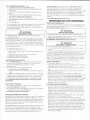
EXpLANATIo\ 0F tll0DEL rrtuvern
(rxnveLr)
I IL.+B
Il->
A *o**,*o
Electronic lgnition or Pilot Belight
Revision (NUVBEB)
Heating Element (scRtw-r\ oR BorT-oN)
4 - 6 - 10 gallon capacity
Engine Heat Exchange
Combination Gas and AC Electric
FIRE OR EXPLOSION
.
)
lf the inlormation in this manual is not lollowed
exactly, a fire 0r explosi0n may result causing
pr0perty damage, personal injury or loss ol Iile.
Do not store or use gasoline or other flammable vapors and
liquids in the vicinity of this or anr other appliance.
WHAT TO DO IF YOU SMELL GAS
. Evacuate ALL persons from vehicle.
. Shut off gas supply at gas container oI source.
. Do \or touch any electrical switch, or use any phone or
radio in vehicle.
. Do \oT start vehicle's engine or electric generator.
. Contact nearest gas supplier or qualified Service Technician
.
for repairs.
If you cannot reach a gas supplier or qualified Service
.
Technician, contact the nearest fire department.
Do Nor turn on gas supply until gas leak(s) has been
repa ired.
Gas (enoenrur)
- IF YOUR MODEL NUMBER IS NOT LISTED0lder revision numbers may be 3, 4, 6,7, 8or g (_____ - X_)
Regardless of your revision number the current instructions are still generally
applicable to your unit. lf you have questions contact your dealer, an Atwood
Service Center or the Atwood Service Department.
MODEL NUMBER CLARIFICATION
cAL
ryPE
4
Pilot lqnition
G4-7
6
Electronic lgnition
Pilot
Reliohl
cAL
eOn-Z
Gn6AA-R
GH6-7
G6A-8E GCH6A-1OE
GC6AA-r0E
Heat Exchanqe
Electronic lonilion
Combination
Gas/Electric
]
GC6AA-8P
GH6-8E
]
]
ro
eal
etO-Z GC10A-2
cr o-zp Gn1 nA-2P
i GlO-3E GCHlOA-4E
I ecton-+p GHr0-3E
P N ruoo$ # - sEE MoDEL cLABrFrcATroN
AB0VE
H tH NoorL # - sEE MoDEr cLARrFrcATroN AB0vE
F rN MonFr # - sFF MnnFr craRrFrcaroN nBnvF
C N rrroo:r. # - sEE MoDEL cLABrFrcAroN ABovE
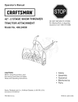
DIMENSIONS
I *,or, [ilt l
GALLoN 6- 12.5'
10 GAr oN
16- 15 5ALL MoDEL
6
1
SHIPPING WT.
6 enrroru 25 lbs
10 cnrioru 32 lbs
.
A c*rncAl
rNsrALLATroN wARNTNGs
.
lnstall in recreation vehicles only. RV's are recreation vehicles
designed as temporary living quarters for recreation, camping, or
travel use having their own power or towed by another vehicle.
. All combustion air must be supplied from outside the RV and all
products of combustion must be vented to outside the RV.
. Do Nor vent water heater with venting system serving another
appliance.
. Do Nor vent water heater to an outside enclosed porch area.
. Protect building materials from flue gas exhaust.
o lnstall water heater on an exterior wall, with access door opening to
outdoors.
. Do Nor modify water heater in any way.
. Do Nor alter water heater for a positive grounding systern.
. Do Nor Hl-POT water heater unless electronic ignition system
(circuit board) has been disconnected (DC Hi-Pot).
. Do Nor use battery charger to supply power to water heater even
when testing.
USA AND CANADA
.
FOLLOW ALL APPLICABLE STATE AND LOCAL CODES
A cou,o*
ELECTRICAL DAMAGE
.
.
norE: lt is recommended unit be connected directly to a 12V DC
battery or to filtered side of an AC/DC converter. Avoid connections to
unfiltered side of an ACIDC converter whenever possible. Use a
minimum of 1B gauge wire. UL and CSA listed.
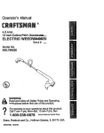
1. Refer to Witing Diagram (Frc 12). lnstall remote switch in a
convenient location. Position wall plate with letters up. Before
-
.
.
.
.
.
Recreation Vehicles ANSI A1 1 9.2/NFPA 501 C.
National Fuel Gas Code ANSI 2223.1 andlor CAN/CGA B149 lnstallation
Codes
Federal Mobile Home Construction & Safety Standard, Title 24 CFR, part
3280, or when this Standard is not applicable, the Standard for Manufactured
Home lnstallations (Manufactured Home Sites, Communities and Set-Ups),
ANSI A255.1 and/or CAN/CSA-2240 MH Series, Mobile Homes.
National Electrical Code ANSIiNFPA No. 70 andior CSA C22.1
Park Trailers A1 19.5
CSA standard 2240 RV Series, Recreational Vehicle.
G
ElI
ERAI
ITI
making connections turn switch 0FF.
2. lnstall wires see FtG 10 & 1 1.
PIL0T RELIGHT - rrc 12
1. Install unit according to GENERAL INSTALLATION instructions.
2. Refer to Wiring Diagram. Use 18 gauge wire. Ul-yCSA listed.
3. Read PIL0T & PILOT RELIGHT 0PERATIONS.
- no 5
1. Push a 5/S" diameter coolant system hose (5-A) lwith SAE 053 A
Type "E"clamp attachedl onto heat exchanger tube (5-B) making a
tight connection.
2. Spread hose clamp and slide toward heat exchange unit past
annular groove (5-C) and release.
3. Continue to HOW T0 0PERATE Y0UR WATER HEATER and/or Electronic
lgnilion 0PERATI0N.
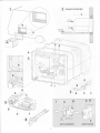
HEAT EXCHANGE MODELS
STATLATIO]I
This is a common installation for water heaters. There are other
approved methods such as Baggage Compartment (MPD 90093) and
Flush Mount (MPD 93948) installations. Consult with your Field
Auditor, Account Manager, or the Atwood Service Department if you
have additional questions.
1. Locate water heater on floor of coach before erecting side walls.
The water heater tank must be permanently supported at the same
level as the bottom of sidewall cutout (by the floor or a raised floor)
nc 2. Provide adequate clearance at rear of unit for service of water
connections.
2. To insiall water heater on carpeting, you must install appliance on a
metal or wood panel that extends at least three inches beyond the
full width and depth of appliance.
3. lf the appliance is installed where connection or tank leakage will
damage adjacent area, install a drain pan (which can be drained to
out side of coach) under water heater.
Label all wires before disconnecting when servicing controls.
operation after servici
Veri
ELECTRONIC IGNITIOT'I
IN THE ABSENCE OF LOCAL CODES OR HEGULATIONS, REFER TO CURRENT STANOARDS OF:
.
When a cord and plug connection to the power supply are used on
water heater, power cord must be UL listed as suitable for damp
Iocations, hard or extra hard usage. lt must be a flexible cord such
as type S, SO, SI STO, SJ, SJT, SJTO, HS or HSO cord as described
in National Electrical Code, ANSI/NFPA 70. The length of external
cord to water heater, measured to face of attachment plug, shall be
no less than 2 feet nor more than 6 feet. Supply cord must be a
minimum of 14 AWG and attachment plug must be rated at 15 amps.
CONTINUE GENERAL INSTALLATION
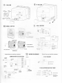
4. Connect bolh 1/2" NPT water lines (rro 2) hot water outlet female
and cold water inlet female and 3/8"flared LP gas line to the water
heater (rrc 9).
a. Allow flexibility in water and gas lines so you can pull unit
forward through wall one inch past skin.
b. Seal gas line entrance opening (rtc 9) by sliding grommet (9-B)
onto 3/8" tubing (9-D) before flaring tubing (9-E). Pull gas line and
grommet through opening in housing (9-A). Connect flare fitting
(9-C) and press grommet into opening. lf gas line tubing is
already flared, cut grommet on one side. Place split grommet
over gas line and press it into opening.
c. Always use pipe lubricant on threads when connecting hot and
cold water couplings. A suitable plastic fitting is recommended.
WIRlNG
All wiring must comply with applicable electrical codes.
COMBINATION GAS/ELECTRIC M0DELS are designed to operate with gas,
electricity, or a combination of both.
. Use electrical metallic tubing, flexible metal conduii, metal clad
cable, or nonmetallic-sheathed cable with grounding conductor. Wire
must have a capacity of 1400 watts or greater. The wiring method
must conform to applicable sections of article 551 of National
Electrical Code ANSI/NFPA 70.
1. Refer to Witing Diaglam (FrG 12). Make 120 VAC electrical
connections from junction box on back of unit.
a. Connect hot lead to (1) Black.
b. Connect common lead to (2) White.
c. Connect ground wire from electrical service to (3) green ground
lead in junction box 3.
A cor,o*
PRODUCT DAMAGE
.
When using Romex@ with a bare earth ground, take care to position
wire so it does not contact the heatinq element terminals.
CAUTION
.
DAMAGE
Do not lift, pull, push or misalign main burner tube (rtc 3-F).
5. Erect side walls and cut opening. See chart and
Frame with 2x2 lumber (or equivalent).
FrG 1.
CUTQUT(Frcl&2)
CAPACITY
Gallon
4-O
'10
CUT OUT DIMENSION
1-A
12-5/g
15-3/4'
DEPTH
1-B
16-1
/4'
16-1/4'
2-C
I
/ -5/d
20-5/8"
MINIMUM CLEARANCE FROM COMBUSTIBLE CONSTRUCTION
Sides: A'
Back: U'
Top:
U'
Bottom: tr
6. Bend all flanges 90" along scored lines (rto 3-A).
7. To prevent water leaks caulk thoroughly around opening, including
bend slots. Butyl Tape (1-1/5'x1/8) may be substituted for caulking
material.
B. Push unit against caulking. secure 4-corner brackets (rto 3-B) to
coach with No. 8 - 3i4" round head screws (not furnished) or equivalent.
Complete the installat on by inserting the same type of #8 screws in the
holes provided around the.lange of the water heater housing. Check all
gaskels. they must adhere t0 the pan crealing an air tight seal.
9. Attach access doc..
a. Snap hinge c r- = , 3-Ct into clip (rtc 3-D).
b. Slide co\,e'
-1-I onto hinge pin.
c, Sllie hirge c -:o cover, snapping into clip at same time (rtc 3-D).
uorE: To rerc. a - -ge oin. support access cover and apply force to
corre. ci t- 'ge oin.
::
-
10. Discc^:e:: ..i^ t a1d lts individual shut-off valve from gas supply
line c-'i^g a.i pressure testing of system in excess of 1/2 PSIG
(3.: <Pa. -r '.','ater column [W.C.]). oo Nor set inlet pressure higher
tl^a. rax .rum indicated on rating plate of gas valve (1 3" W.C.).
lso a:: -- t from gas supply line by closing its individual manual
sri:ci: ', arve during any pressure testing < 1/2 psig.
A
. ra ',1-
*o*N,nc
use matches, candles or oiher sources of ignition when
1. Turn on gas and check water heater and all connections for gas
leaks lvith leak detecting solution.
'1
2. Fil rvater heater tank, check all connections for water ieaks.
1
PRESSURE-TEMPERATURE RELIEF VALVE
GO]ISUMER SAFETY WARNI]IGS
WARNING
EXPLOSION OR
.
Do Nor store or use gasoline or other flammable vapors and liquids in
the vicinity of this or any other appliance.
. Should overheating occur, or gas supply fail to shut off, turn OFF
manual gas control valve to appliance, or turn gas 0FF at the LP
tank. On ELECTR0NIC lGNlTl0N M0DEL turn operating switch to OFF
position and remove red wire from left hand terminal of ECO switch
or turn gas OFF at the LP tank.
. Use with LP gas only.
. Shut off gas appliances and pilot lights when refueling.
. On PIL0T RELIGHT MODELS, turn off the ignition module when
refueling gasoline tanks or LP tanks.
. Turn gas OFF at the LP tank when vehicle is in motion. This disables
all gas appliances and pilot lights. Gas appliances must never be
operated while vehicle is in motion. Unpredictable wind currents
may be created which could cause flame reversal in the burner
tube. which could result in fire damage. The thermal cut otf fuse
could also be unnecessarily activated resuliing in a complete
shutdown of the water heater requiring replacement of the thermal
cut off, See maintenance of electronic ignition water heaters for
further explanation of the thermal cut off.
. LP tanks must be filled by a qualified gas supplier only.
HOW TO OPERATE YOUR WATER HEATER
WARNING
A cournon
EXPLOSION
. Valve is not serviceable, it must be replaced.
. Tampering with valve will result in scalding injury.
. Tampering with valve will void warranty.
. rc
Nor place a valve, plug or reducing coupling on outlet part of
relief valve.
THIS VALVE IS A SAFETY COMPONENT AND MUST NOT BE HEMOVED FOR ANY BEASON
oTHER THAN BEPLACEMENT. This water heater is equipped with a
temperature and pressure relief valve (rtc 3-G) that complies with
standard for Relief Valves and Automatic Gas Shutotf Devices for Hot
Water Systems, ANSI 221.22.
lf water heater has not been used for more than two weeks, hydrogen
gas may form in water line. Under these conditions to reduce the risk
of injury, open hot water faucet for several minutes at kitchen sink
before you use any electrical appliance connected to hot water system.
lf hydrogen gas is present, you will probably hear sounds like air
escaping through the pipe as water begins to flow.
lf you use a discharge line, do not use a reducing coupling or other
restriction smaller than outlet of relief valve. Allow complete drainage
of both valve and line.
FOR REPLACEMENT PARTS:
. Do Nor install anything less than a combination temperature-pressure
relief valve certified by a nationally recognized testing laboratory that
maintains periodic inspection of product of llsted equipment or
materials, as meeting requirements for Relief Valves and Automatic
Gas Shutoff Devices for Hot Water Supply Systems, ANSI 221 .22.
Valve must have a maximum set pressure not to exceed 150 psi.
. Install valve into opening provided and marked for this purpose on
.
.
water heater.
lnstallation must conform with local codes or in the absence of local
codes, American National Standard for Recreational Vehicles, ANSI
41 19,2/NFPA 5OIC.
For an external electrical source, ground this unit in accordance with
National Electrical Code ANSI/NFPA70.
Your ATWOOD PIL0T GAS WATEB HEATER is now ready for operation.
Continue to HOW T0 0PERATE Y0UR WATER
HEATER
WARNING
NG INJUBY
o Do not tamper with pilot orifice.
CAUTION
PRODUCT FAILURE
.
Do not operate without water in tank.
PILOT OPERATION
1. Water heater may be equipped with a White Rodgers@ or
Robertshaw Unitrol@ Control rro 7.
2. Turn gas control valve knob (rro 7-B) to OFF position.
3. Wait at least five minutes to allow accumulated gas in burner
compartment to escape.
FOR WHITE RODGERS'CONTROL (rro 7)
a. Turn iighting control knob (7-B) to PILOT position and hold
against stop while lighting pilot burner.
b. Allow pilot to burn thirty seconds then release lighting control
knob.
c. Turn lighting control knob (7-B) to 0N position.
d. lf pilot does not remain lit, repeat operation allowing longer
period before releasing lighting control knob.
e. Set temperature selection lever (7-A) at mark between warm and
hot position.
f. Close access door.
FOR A ROBERTSHAW UNITROL@ (rro 7)
a. Turn lighting control dial (7-B) to PILOT position.
b. Depress and hold reset push button (7-A) while lighting pilot
burner (7-C).
c. Allow pilot to burn thidy seconds before releasing reset push
button.
d. lf pilot does not remain lit, repeat operation allowing longer
period before releasing reset push button.
e. Turn lighting control dial (7-B) to 0N position.
f. Set temperature control dial (7-C) at mid-point position between
warm and hot.
g. Close access door.
4. For complete shut down and before servicing, turn gas control knob
(rro 7-B) to OFF position. When water heater is not in use set
temperature control lever (White Rogers@) or dial (Roberlshaw@) to
lowest possible position.
The unit can be run in both gas and electric
modes simultaneously for quick recovery. note: if the gas fails to
ignite, the gas mode will lockout. but the Iockout lamp will not
illuminate since the electric mode is still operational. Should you notice
slow recovery, indicating the gas is not working, turn the electric
switch off. The lamp will ihen illuminate indicating a lockout has
occurred on the gas side. Correct the problem and turn the switches
back on.
GAs/ELEcrBrc opERATroN.
Read
MAINTENANCE AND CARE li{STRUCTI()NS.
MAIIITEIIAI{GE A}I D GARE I]{STRUGTIO]IS
SERVICE CALLS
& OUESTIONS
Location and phone numbers of ota,ified Service Centers can be found
at our website http:/www.atwoodmca e.com or call 574-262-2655 to
have a Service Center List mailec.
WABNING
WARN!NG
SCALDING INJ
.
Setting temperature control dial at a higher position will produce
excessively hot water.
The temperature knob or lever is factory adjusted to its lowest dial
setting. We recommended the mid-point position between warm and
hot, as noted above. This will provide for energy efficient operation
and sufficient hot water. Valves for reducing point of use temperature
by mixing cold and hot water are available. Consult a licensed plumber
or local plumbing authority.
5. To Adjust Main Burner (rrc 4):
1. Loosen air shutter screw (4-A).
2. Slide air shutter (4-B) to right until some yellow appears in main
burner flame.
3. Move air shutter (4-B) to left until yellow disappears.
4. Retighten air shutter screw (4-A).
Read
MAINTENANCE AND CABE INSTRUCTI0NS
ELECTRONIC IGNITION OPERATION
1. Refer to WIRING DIAGRAM rrc 12. Place remote switch in 0N position.
2. lf remote switch light stays on longer than 15 seconds. place
remote switch in 0FF position and wait 5 minutes.
3. Repeat step one.
4. For complete shut-down and before servicing:
a. Place remote switch in 0FF position.
b. Remove red wire from left hand terminal of ECO switch (ECO to
valve).
5. lf heater fails to operate due to high waier temperature. a lockout
condition occurs (indicator light on). After water cools. reset switch
in OFF position for at least 30 seconds, then turn to 0N position.
6. lf a lockout condition persists contact an Atwood Service Center.
Read MAINTENANCE AND CABE INSTRUCTI0NS & ELECTH0NIC lGNlTl0N
.
.
2. Read PILOT 0PERATI0N instructions.
3. For complete shut down, turn llghting control knob on thermostat
and spark module switch to the 0FF position.
Read
MAINTENANCE AND CARE INSTRUCTIONS
GAS/ELECTRIC COMBINATION FUNCTION
When the gas switch is turned on, the unit will make three
attempts to light. lf for any reason there is no ignition, the unit will
lockout and the red lockout lamp will illuminate. lf the thermostat fails,
the ECO will also lockout the unit, requiring resetting. Determrne the
reason for no ignition, correct it, and reset the gas ignition sequence
by turning the switch off, then on.
GAs 0PERAT|0N.
When the electric switch is turned on, the relay at the
rear of the unit will close and pass 110vac to the element. lf the
thermostat were to fail, the ECO will open and lockout the system. To
correct, check the thermostat to assure good contact with the tank
and reset the control by turning the electric switch off, then on.
ELEGTRTC
0PERAT|0N.
Keep control compartment
clear
material, and flammable liouids
:-:
a-c
a gas line.
'.ee of gasoline, combustible
.acc!"s.
AFTERMARKET WATER HEATING ELEhIENT DEVICES
A *o**,*o
IXJURY
.
.
Do Nor alter water heater, it will void :,a:-?'::
Do Nor usr Aftermarket heating eler,re
:-3,.
.
controls.
Use of Aftermarket heating eleme":s
s
:-a- a:x critical safety
.?' :.-::: a- out of control
: ,,,:: s := =rclosion.
The use of any aftermarket heating e 3-:-:
-a;, also result in
':ie1 warranty
damage to components or water heale. :
states - "failure or damage resulttng '.::i :c our water
heating of water tank and a catas:.:3-
,
heater is the owner's responsibiliti" . :-_.
an aftermarket heating element de'.':: ,,,
GENERAL INFORMATION
. LP and Water system must b:
. Have gas pressure tested pe'
'.-.'=.
:rie addition of
<=
,J=
L)
=
-^
.. :z . S-c - : :: set at 1 I inches of
water column with three app a-::-< '-"':
. Drain water heater at regula' ^::',: -. a: :as: 3.e time during the
.
.
.
.
MAINTENANCE
PILOT RELIGHT OPERATION
1. Turn the switch located on the spark module to the 0N position.
Shut off gas supply
FIRE OR EXPLOSION
at LP containe. ::'cre disconnecting
year).
Drain water heater before sic.
possibility of freezing exists.
Keep vent and combustior, e'
^: =. ':, :-e ,,,,tnter or when the
j' : =ar of any obstructions.
Periodically, compare flar.'e c' -a - and pilot burners with Ftc 5 and
main burner adjustments : HoW T0 oPERATE Y0UH WATER HEATER.
When water heater is noi ," -se se: temperature control lever (White
Rogers) or dial (Robertsha',,,, :c .c''vest possible position. This will
reduce the effects of lo',,, cJ:Coor temperatures on calibration of
temperature control Tnec-a':,sm:
ELECTRONIC IGNITION MAINTENANCE
.
The water heater comes factory-equipped with a fused circuit board,
which will protect the circuit board from wiring shorls. lf the fuse
should activate, the v,,aier heater will not operate. Before replacing
the fuse, check for a shod external to the board. Once the shod is
corrected, replace the 2 amp fuse with a mini ATO style fuse. Do nol
install a fuse larger than 3 amps.
o lf the fuse is good and the unit is inoperative, check for excessively
high voltage to the unit (more than 14 volts).
. lf the previous two steps did not solve the problem, check the
thermal cut-off (Ftc 3-l). The thermal cutoff is a device installed in the
power supply line. This device will shut off electrical power and stop
heater operation when activated. For example, if an obstruction
within the flue tube should occur, as described in the Preventative
Maintenance section, the burner flame/heat may contact the cutoff,
resulting in a melting of the fuse element incorporated in the
thermal cutoff. In order to restore power and proper operation of the
water heater, the obstruction must be removed and the thermal
cutoff must be replaced.
PREVEI{TATIVE MAI NTEI{AI{GE
Spiders, mud wasps, and other insects can build nests in the burner
tube. This will cause poor combustion, delayed ignition or ignition
outside combusiion tube. Listen for a change in burner sounds or in
flame appearance from a hard blue flame to a soft lazy flame or one
that is very yellow. These are indications of an obstruction in burner
tube (rrc 4-C). lnspect and clean on a regular basis.
a. Remove air shutter screw (rro 4-A) and slide air shutter (rrc 4-B)
dorvn burner tube.
b. Run a flexible wire brush down burner tube (no 4-D) until it is
visible at end of burner tube.
c. Vacuum burner where it enters combustion tube.
d. Retum
air shutter to original position and replace screw.
e. The orilice, burner tube and shutter must be aligned s0 that the shutter is nol
binding on the air tube.
T0 CLEAN PIL0T M0DELS - rte s
1. Check main burner orifice and pilot assembly for contamination
HOW
(dirt, spider webs, etc.).
2. Clean main burner tube with small brush.
3. Main burner adjustment - open air shutter 1/4 way.
4. Low pilot flame. Check for contamination - if clean have the pilot
orifice replaced.
HOW TO CLEAN ELECTRONIC IGNITION MODEL
1. Check main burner orifice.
2. Clean and ad.just main burner.
3. Main burner and valve manifold must align with each other
4. Check electrode for cracked porcelain (rrc 4-E).
5. Check electrode for proper gap - 1/8" between electrode and
ground.
6. lf module board functions intermittently. remove board and clean
terminal block with pencil eraser (nc 3-H).
WATER HEATER TANK CARE
WARNING
SCALDING INJURY
. Turn off water heater and allow time for water to cool before
inq drain pluq to flush tank.
wtl{TERtZtl{G (FrUSHrilG} rI{STRUCTT0ilS
To insure the best performance of your water heater and add to the life
of the tank, periodically drain and flush the water heater tank. Before
long term storage or freezing weather drain and flush the tank.
1. Turn off main water supply (the pump or water supply (the pump or
water hook up source).
2. Drain Water Heater Tank by removing the drain plug- lf the water
flows sporadically or trickles instead of a steady stream of water, we
recommend the following action: first open the Pressure
Temperature Relief Valve to allow air tnto the tank and secondly,
take a small gauge wire or coat hanger and poke through the drain
opening to eliminate any obstructions.
3. After draining the tank, because of the placement of the Drain Plug,
approximately two quarts of water will remain in the tank. This water
contains most of the harmful corrosive particles. To remove these
harmful corrosive particles flush the tank with either air or water.
Whether using air or water pressure, it may be applied through the
inlet or outlet on the rear of the tank or the Pressure Temperature
Relief Valve. (lf using the Pressure Temperature Relief Valve the
Support Flange must be removed). The pressure will force out the
remaining water and the corrosive pafticles.
lf you use water pressure, pump fresh water into the tank with the
assistance of the on-board pump or use external water for 90
seconds to allow the fresh water to agitate the stagnant water on
the bottom of the tank and force deposits through the drain
opening. Continue repeating adding water and draining until the
particles have been cleared from the water remaining in the tank.
4. Replace the Drain Plug and close the Pressure Temperature Relieve
Valve. the approximately two quarts of water remining in the tank after
draining will not cause damage to the tank should freezing occur.
PRESSURE.IEMPERAIUBE RETIEF UATVE
WARNING
EXPLOSION
.
Do not place a valve, plug or reducing coupling on outlet part of
pressure-temperature relief valve.
A Pressure Temperature Relief Valve, dripping while the water heater is
running, DOES NOT mean it is defective. During normal expansion of
water, as it is heated in the closed water system of a recreation
vehicle, the Pressure Temperature Relief Valve will sometimes drip. The
Atwood water heater tank is designed with an internal air gap at the
top of the tank to reduce the possibility of dripping. ln time, the
expanding water will absorb this air and it must be restored. Due to
variations in water quality, the Pressure Temperture Relief Valve may
have a shorter life and may need replacement within the water heater
warranty period. lf corrosion is detected, it will not be covered under
warranty.
A wonr,nc
SCALDING INJURY
. Turn off water heater before opening pressure-temperature relief
valve to establish air space. Storage water must be cool.
TO REPLACE THE AIR GAP FOLLOW THESE STEPS:
1. Turn off main water supply (the pump or water hook up source).
2. Let water cool or let run until cool.
3. Open the hot water faucet closest to the water heater.
4. Pull handle of pressure temperature relief valve straight out and
allow water to flow until it stops.
5. Allow pressure temperature relief valve to snap shut; close faucet;
turn on water supply.
6. Turn on water heater and test.
. At least once a year manually operate pressure-temperature relief
valve (rrc 16).
When pressure-temperature relief valve discharges again, repeat above
procedure. For a permanent solution, we recommend one of the following:
. lnstall a pressure relief valve in cold water inlet line to water heater
and attach a drain line from valve to outside of coach. Set to relieve
at 100-125 PSl.
. lnstall a diaphragm-type expansion tank in cold water inlet line. Tank
should be sized to allow for expansion of approximately 15 oz. of water
and pre-charged to a pressure equal to water supply pressure. These
devices can be obtained from a plumbing contractor or service center.
FTUSHII{8 IO REMOVE UNPIEASAI{T ODOR
A rotten egg odor (hydrogen sulfide) may be produced when the electro
galvanic action of the cladding material releases hydrogen from the
water. if sulfur is present in the water supply the two will combine and
produce an unpleasant smell.
1. Turn off main water supply. Drain the water heater tank and reinstall
drain plug. Remove the pressure-temperature relief valve. Mix
solution of 4 parts white vinegar to two parts water. With a funnel,
carefully pour solution into tank.
2. Cycle water heater with the above solution, letting it run under
normal operation 4-5 times.
3. Remove the drain plug and thoroughly drain all water from the tank.
Flush the water heater to remove any sediment. You may flush the
tank with air pressure or fresh water. pressure may be applied
through either the inlet or outlet Valves on the rear of the tank or
through the pressure-temperature relief valve coupling located on the
front of the unit.
TO FLUSH TAN( WITH AIR PRESSURE:
lnsed your air pressure through the pressure-temperature relief
valve coupling. With the drain valve open, ihe air pressure will force
the remaining water out of the unit.
To llush lank with water pressure:
Fresh water should be pumped into the tank with either the
onboard pump or external water pressure. Continue this flushing
process for approximately 5 minutes, allowing the fresh water to
agitate the stagnant water on the bottom of the tank and forcing
the deposits through the drain opening.
4. Replace drain plug and pressure-temperature relief valve.
5. Refill tank with fresh water that contains no sulphur.
The Atwood water heater is designed for use in a recreation vehicle. lf
you use your vehicle frequently or for long periods of time, flushing the
water heater several times a year will prolong the life of the storage tank.
Hot Water
0utlet4
Cold Water
lnlet\
1' A
'J_/"
06
GAtLOil
.-.=\
\1
i1
BUCK
TO ELEMENI
t1
@la
.,1
_r_t
-^|_
.S_,
'a@i4
l
o-T---F@
GREEN GROUP
NOT BUCK
TO STUD
USED llOVHOT
-li
-\.O
n-t==--t
l
l
--
l
Y
---l-------
t-'i'l
'l
I
---]l
)
i,,zt
i'9
L
\@tr-:-A
\\ u I .=4)-l
i
.
@ t,*ntE swtTGH
----r@rr-\-
c-\
--
BLUE
FROi',1
'Ji
-
(L0cK-0uT rAMP,
+1 2
VDC
GAS- ORANGE FROI\,4 WH
ELEC -WHITE FROI\4 WH,
JUMPER WIRE
+1
2 VDC
WHITE FROIM W.H.
(ELECTRIC)
GREEN FROIV] W.H,
(GROUND)
JUMPER WRE
Dotted !!nes are wlred by gystomer
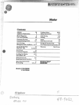
COMBIilATIOl{ GAS/EtEGTRIG
@
wrnrilG
Dotted lines are wired by customer
DTAGRAMs
PII.OT RETIGHT
BLANK 4
REMOTE
swtTcH
ELECTRIC
j
*lz 4
wc +/e
CBEEN
High Voltage Lead
t0
Burner Electrode
RED
RETIOTE
LOCK.OUT
LAHP
.-
11llv ELECIBIG/GAS PITOT Ol{tY
FIXED TEMP
CONT T-STAT
1t5V
Switch
THERMAL
CUT-OFF
I{EURTAL
Ho! leqq
Common Lead
BLACK
o
(3
)-GBEEN
-(2)-wHrrE
.g\''/\r--
Ground
[r,
,. BLA0K ?
Erement
15Y
HOT
1
GRH
(1
I
Gf9!'!q lgqq
U}fT
.--)-BLACK ..'
GREEN
rireO Thermosrat
11lanuarReset
l'flll'#,or'|l'n'"
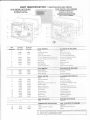
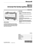
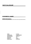
PART IDENTIFICATION
/
PILOT IGNITION / PILOT RELIGHT
IDENTIFICATION DES PIECES
SPARK IGNITION / HEAT EXCHANGE
ALLUMAGE PAR ETINCELLES /
EcHRHor DE cHALEUR GAz-
ALLUMAGE DE VEILLEUSE /
RALLUMAGE DE VEILLEUSE
REFERENcE 22
2
3
4
5
6
7
8,/
rrrR=s
90960
91857
91604
90028
91602
92615
91603
38
rtrnes
PILOT
x
*Tank
90960
91 857
91
604
90028
91 602
93221
91 603
IGNITION
AILUIIAGE DE
.' ."
=,:
::-:-c^
Flue Box Assembly
Drain Plug
(shown on spark ignitiont
rElllEgSE-
conduit
de vidange
a rmage 6lectronique)
S: -:ape de d6charge de tYPe
S:-cape de d6charge
-'
1/2 NPT Pressure-TemP r: :' ,:
3i4" NPT Pressure-Terc.=: :' .: .=
Thermostat
Main Burner
Pilot Assembly
Exterior Access Door
--e.mostat
3'-,eur principal
. e leuse
-'appe d'accds ext6rieur
PILOT RELIGHT
RALLUMAGE DE VEILLEUSE
93801
93801
Spark Module
IO
93804
93803
93804
93803
Electrode Assembly
Wiring Harness
l,4odule d'allumage
Electrode
Faisceau 6lectrique
SPARK IGNITION
ALLUMAGE PAR ETINCELLE
1
x
x
*Tank
R6servoir
Boitier du conduit
Bouchon de vidange
Soupape de decharge de tYPe
I
10
4
90960
91 857
91 604
90960
91 857
91 604
Flue Box Assembly
Drain Plug
o
93844
93844
Solenoid Valve
Black on-Off Switch
White On-Off Switch
Circuit Board
Wiring Harness
Thermal Cut Off
Spark Probe
Electrovanne
Thermostat/ECO
ThermostaVECO
HEAT EXCHANGE
Ecxance DE cHALEUR
*Tank
R6servoir
2
3
11
91
959
91
91
859
91
959
859
12
93851
93851
13
931 91
931 91
16
93866
93868
91447
93866
93868
91447
17
.,1
NS
NS
X
92249
93849
Pressure-Temperature Fe
3' ,: .:
lnterrupteur Marche/Arr6t noir
nterrupteur Marche/Arr6t blanc
Circuit imprim6
I
Faisceau 6lectrique
Coupure thermique
D6tecteur d'6tincelle
-
ELEGTRICITE COMBINES
COMBINATION GAS/ELEGTRIC
GAZ
x
92249
*Tank
93849
Relay
R6servoir
El6ment de chauffe ei ioint
Relais
Heating Element & Gasket
*
x
All tanks includes styrofoam jacket = Tous les r6servoirs comprennent une chemise de polystyrene.
Order by model = Commander selon le moddle
Order by color = Commander selon la couleur
8