1
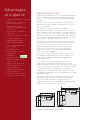
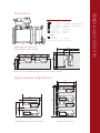
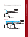
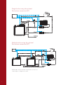
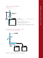
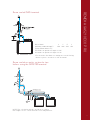
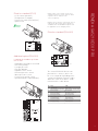
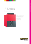
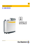
REMEHA GAS 210 ECO PRO The Remeha GAS 210 ECO PRO Condensing Boiler Range SUPER CONDENSING HIGH EFFICIENCY FULLY MODULATING 107% NCV ≥ 82/71°C 108.6% NCV ∆T 40/30°C BOILER CONTROL PREMIX BURNER CLEAN COMBUSTION ULTRA LOW NOx BREEAM EXCELLENT RECYCLABLE MATERIALS High Efficiency Floor Standing Fully Condensing Boiler with excellent ultra low NOx emission PANTONE 287 EC PANTONE 2985 EC PANTONE Process Black EC PANTONE 200 EC OUTPUTS: GAS 210 ECO PRO - 3 16 - 87 kW - 4 22 - 120 kW - 5 29 - 166 kW - 6 39 - 200 kW PANTONE 287 EC PANTONE 2985 EC PANTONE Process Cyan EC PANTONE 376 EC PANTONE Process Cyan EC Introduction The Remeha Gas 210 ECO PRO is a compact floor standing condensing boiler. The small footprint and ability to be installed back to back makes it ideally suited for modular configurations. An optional Optimising Weather Compensating control package is available to ensure maximum efficiency. Now also compatible with Open Therm. The boilers are suitable for both new and retrofit applications. With conventional and room sealed flue capability they can be installed in most situations. Full installation and technical details can be found in the Gas 210 ECO PRO Installation and Service Manual, available on our website or by contacting us on 0118 978 3434 Boiler description The Remeha Gas 210 ECO PRO boiler is a pre-assembled, free standing, gas fired, high efficiency condensing boiler. The sectional cast aluminium heat exchanger and other major components are contained within a sealed air box. This forms the main boiler casing with a removable front panel section for maintenance purposes. All electrical and electronic controls are contained within the instrument panel mounted on top of the boiler. The flue gas outlet, combustion air inlet, flow, return and gas connections are located on the top of the boiler with a condensate connection and optional return connection at low level on the right hand side. The boiler is suitable for room sealed or open flue applications and has been designed for central heating and indirect hot water production at working pressures not exceeding 6 bar. It must be installed on a fully pumped pressurised system (minimum operating pressure 0.8 bar). The pre-mix, down firing gas burner (NG + Propane only) with its gas/air system ensures clean, trouble free operation with higher than average efficiencies of 108.6% (NCV) in the condensing mode, combined with ultra low NOx and minimum CO2 emissions. The standard control package allows actual and set values to be read and adjusted on the built-in digital display, which also provides normal operating and fault code indication. An intelligent, advanced boiler control (abc®) continuously monitors the boiler conditions, varying the heat output to suit the system load. The control is able to react to external “negative” influences in the rest of the system (flow rates, air/gas supply problems), maintaining boiler output for as long as possible without resorting to a lock out condition. At worst the boiler will reduce its output and/or shut down (shut off mode) awaiting the “negative” conditions to return to normal before re-starting. The abc® control cannot override the standard flame safety controls. Every Remeha Gas 210 ECO PRO is checked, following assembly, by means of a test computer to ensure its proper operation. Contents page - 90/396/EEC - 92/42/EEC - 89/336/EEC Gas appliances directive Efficiency directive E.M.C. directive Introduction 2 Boiler description 2 Boiler construction 3 Efficiency/application information 3 Advantages at a glance 4 Operating principle 4 Dimensions 5 CE Certification Technical data 6 Reference number 0085BS0132 NOx-Reference number BS004 Typical installation 7-8 Typical flue installation 9-11 Electrical connections and controls 12-15 2 The boiler meets the requirements of the EC regulations of the directives: and complies with the following requirements: - 73/23/EECElectrical low voltage directive. -97/23/EEC Pressure equipment directive. Article 3, Sub.3 1. Air supply 2. Flue gas outlet 3. Combustion test point (O2/CO2) 4. Sealed air box 5. Differential air pressure switch (LD2)* 6. Venturi 7. Air supply fan 8. Premix, fibre faced burner 9. Combined ignition/ionisation probe 10. Sight glass 11. Gas combi-block 12.Cast aluminium, sectional heat exchanger 13. Temperature sensor - flow* 14. Temperature sensor - return* 15. Temperature sensor - heat exchanger* 16. Temperature sensor - flue gas (option)* 17. Drain pan (condensate) 18. Condensate connection 19. Heat exchanger inspection hatch 20. Instrument panel 21.Facility for incorporating a weather compensator (optional) 22. Boiler setting keys 23. Read-out display and reset key 24. On/off switch 22 23 1 2 26 21 24 3 4 27 25 20 10 8 7 9 19 11 6 12 28 17 18 25. Gas connection 26. Flow connection 27. Return connection 28.Drain cock and optional second return connection or low level return (option) *Not illustrated REMEHA GAS 210 ECO PRO Boiler construction Annual efficiency Up to 108.6% at Hi (up to 97.8% at Hs) at an average return water temperature of 30°C (40/30°C). Heat to water efficiency a. Up to 98.4% at Hi (88.6% at Hs) at an average water temperature of 70°C (80/60ºC). b. Up to 105.7% at Hi (95% at Hs) at an average water temperature of 40°C (50/30ºC). Standing losses On average, 0.21% at Hi (0.23% at Hs) at an average water temperature of 45°C. NOTE: NCV = Hi, GCV = Hs. Application information The Gas 210 ECO PRO can be used on all new and refurbishment projects in both single and cascade configurations. Conventional and room sealed flue system capability means that the boiler can be sited almost anywhere within a building. The Remeha range of weather compensators (option) are able to communicate directly with the boiler controls to make full use of its fully modulating feature, ensuring that the boiler closely matches the system demand at all times. Our range of external control systems can be interfaced with the boiler to provide on/off or modulating (0-10V) control options. For cascade flue arrangements a motorised flue/gas damper is available as an accessory. The optional SCU- S01 PCB will also be required. A key benefit of the Remeha Gas 210 Pro is that it is Renewable Energy Ready. Most renewable energy products need to be backed up by a condensing boiler during periods of peak demand. The secondary return feature on the Remeha Gas 210 Pro makes this boiler particularly suitable for use with renewable energy technologies that use low grade heat such as heat pumps or underfloor heating circuits. Bivalent systems such as this combine the best of renewable and conventional heating technologies to maximise the seasonal efficiency of the system as a whole over the course of the year. 3 Advantages at a glance Operating principle Combustion air is drawn into the closed air box through the air inlet from the plant room (open flued) or from outside via the eccentric flue system (room sealed) by a variable speed fan. •Compact lightweight construction •High efficiency - 108.6% NCV at 40/30°C (97.8% GCV) The inlet side of the fan is fitted with a venturi, where air and gas are mixed according to a fixed ratio. This ensures precise combustion. •Boiler controls - On/Off High/Low or Fully modulating over 18-100% This mixture is initially ignited by the combined ignition/ionisation probe which monitors the state of the flame. Should the flame be unstable or not ignite within the pre-set safety time cycle, the controls will (after 5 attempts) shut the boiler down, necessitating manual intervention to reset the boiler. The digital display will indicate a flashing fault code confirming the reason for the failure. •Premix burner for optimum combustion •Low NOx < 38 expected seasonal • Ultra quiet < 59 dBA • Digital diagnostic display The products of combustion in the form of hot flue gases are forced through the heat exchanger transferring their heat to the system water (the flue gas temperature is reduced to approximately 5°C above the temperature of the system return water), then discharged via the condensate collector, vertically through the 150mm connection to the atmosphere. • Remote signalling options •Cast - sectional aluminium heat exchanger • Easy maintenance •Options for direct weather compensation Because of the low flue gas exit temperature there will be a vapour cloud formed at the flue gas terminal - this is not smoke, simply water vapour formed during the combustion process. •Compatible with Open Therm •Advanced intelligent (abc®) control system If the controls allow the flow and therefore return temperature to fall below dew point (55°C), this water vapour will begin to condense out in the boiler, transferring its latent heat into the system water, increasing the output of the boiler without increasing the gas consumption. • Diagnostic PC connection •Conventional or “room sealed” capability •Supplied fully assembled for ease of installation Condensation formed within the boiler and flue system is discharged from the boiler to an external drain via the drain pan/siphon supplied. •Renewable ready - optional low level secondary return kit The boiler can be supplied, as an option, with a second (fixed temperature) return connection. This additional connection enables the boiler to make full use of its condensing ability whilst accepting both fixed and variable temperature returns from the same system. 1490 1890 250 450 190 450 1490 1190 1690 1190 1690 1190 450 1050 50 50 600* * Minimum 600mm. We recommend 1m 4 250 1890 450 250 450 50 1190 1190 250 3/4/5 Section REMEHA GAS 210 ECO PRO Dimensions 6 Section Gas - 1 /4” BSP(M) 11/4” BSP(M) Return - 1 /4” BSP(M) 11/2” BSP(M) (when supplied adapter fitted) Flow - 1 /4” BSP(M) 11/2” BSP(M) (when supplied adapter fitted) Flue Gas 150mm i/d 150mm i/d 32mm o/d plastic 32mm o/d plastic Air in 150mm i/d 150mm i/d ‘A’ height - 1309mm 1324mm Optional 2nd Return* 11/4” BSP(M) 11/4” BSP(M) 1 1 1 *or optional low level secondary return connection Maintenance area for two boilers side to side * * NOTE: For other configurations, please consult technical manual Space saving configurations 1490 1190 250 600* 600 450 250 600 900 450 1190 600 *minimum 600mm we recommend 1m 3000 450 900 600* 450 3000 250 450 1190 450 *minimum 600mm we recommend 1m * Minimum 600mm. We recommend 1m 600 1500 1490 50 1490 50 1500 250 450 50 1190 50 1490 All dimensions in mm All dimensions in mm 5 Technical data Boiler type Remeha Gas Remeha Gas Remeha Gas Remeha Gas 210 ECO PRO 210 ECO PRO 210 ECO PRO 210 ECO PRO 80 120 160 200 General Number of sections qty 3 Input control o 4 5 6 Modulating, 0-10 V or on/off Nominal output (80/60 C) Pn min. kW 16 22 29 39 max. kW 87 120 166 200 o Nominal output (50/30 C) Pn min. kW 18 24 33 44 max. kW 93 129 179 217 Nominal input gross caloric value (GCV/Hs) Qnmin. kW 19 26 34 46 max. kW 99 137 189 228 Nominal input net caloric value (NCV/Hi) Qn min. kW 17 23 31 41 max. kW 89 123 170 205 Gas and flue gas side Category II2H3P Inlet gas pressure natural gas 17/30 mbar Gas consumption natural gas min. m03/h 1.8 2.4 3.3 4.3 Gas consumption natural gas max. m03/h 9.4 13.0 18.0 21.7 NOx emission @ 0% O2 mg/kWh < 33 < 35 < 38 < 37 130 130 130 130 Residual fan pressure Pa Flue gas quantity min. kg/h 27.2 36.7 49.5 65.5 Flue gas quantity max. kg/h 149.7 206.9 286.0 344.9 Type classification with respect to flue gas discharge B23, B23p, C13, C33, C43, C53, C63, C83 Central heating side High limit temperature °C 110 Operating temperature range °C 20 - 90 Minimum water working pressure bar 0.8 Maximum water working pressure PMS bar 6 Water content litres 12 16 20 24 Hydraulic resistance at ∆T = 20°C mbar (kPa) 165 (16.5) 135 (13.5) 170 (17) 180 (18) Hydraulic resistance at ∆T = 11°C mbar (kPa) 545 (54.5) 446 (44.6) 562 (56.2) 595 (59.5) Electrical Main voltage V/Hz 230/50 Input power (without pump) min. Watt 4 4 4 4 max. Watt 125 193 206 317 165 188 Insulation class IP 20 Other Weight excluding water kg 115 135 Noise level at a distance of 1M from boiler (enclosed version)dB(A) Environment temperature Colour of casing °C 0 - 40 RAL2002(red) / 7037(grey) NOTE: For Firing on LPG, please contact our sales department 6 ≤59 Please Note: These layouts do not constitute a design. Calculations must be carried out to ensure pipework and pumps are sized to match boiler nominal flows against system design flow requirements. Single boiler REMEHA GAS 210 ECO PRO Typical installations Multiple boiler 7 Single boiler using the optional 2nd return connection (VT) Multiple boiler using the optional 2nd return connection (VT) NOTE: 2nd return for variable temperature or low level return in place of high level return 8 (Conventional) Boiler Model Maximum length ‘L’ (Using 150mm diameter*) 3 4 5 6 50M 50M 45M 31M 45° bend = an equivalent length of 1.2M 90° bend = an equivalent length of 2.1M (Using 150mm diameter flue) *For alternative flue diameters and greater overall flueing distances please consult the technical manual. REMEHA GAS 210 ECO PRO Typical flue installation Conventional flue with two boilers using a common header arrangement NOTE: Flue calculation must be carried out to confirm header sizes. Please consult with our technical department. 9 CLV system (two zone) Boiler Model Maximum combined length ‘L’ (Using 150mm diameter*) 3 4 5 6 36M 36M 23M 11M 45° bend = an equivalent length of 1.2M 90° bend = an equivalent length of 2.1M *For alternative flue diameters and greater overall flueing distances please consult the technical manual. CLV flue system with two boilers using a common flue and air inlet header arrangement NOTE: Flue calculation must be carried out to confirm header size. Please consult with our technical department. 10 Boiler Model Maximum combined length ‘L’ (Using 150mm diameter*) 3 4 5 6 30M 30M 22M 13M 45° bend = an equivalent length of 1.2M 90° bend = an equivalent length of 2.1M REMEHA GAS 210 ECO PRO Room sealed GVRS terminal *For alternative flue diameters and greater overall flueing distances please consult the technical manual. Room sealed eccentric system for two boilers using the GVRS 250 terminal NOTE: Flue calculation must be carried out to confirm max lengths. Please consult with our technical department. 11 Electrical connections and controls General specifications The Remeha Gas 210 ECO PRO is supplied as standard with electronic control and flame ionisation safety controls, with a specially designed microprocessor at the heart of the control system. Power supply The appliance is suitable for a supply of 230V-1-50Hz 6.3amp with phase/neutral/earth. NOTE: the controls are phase/neutral sensitive. Automatic controls SIT Type: PCU-01 Electrical supply: 230V -1-50 Hz Power consumption at standby/part load/full load: - 3 sections: 4 / 36 / 125 W - 4 sections: 4 / 37 / 193 W - 5 sections: 4 / 53 / 206 W - 6 sections: 4 / 54 / 317 W Maximum power output to pump: 300 VA. Fuse specification The boiler is protected by fuses: - Fuse F on the 230v terminal strip 6.3AT On the control box: - F1 rated at 1.6 amps (fast acting)control circuit 230V Boiler temperature control The Remeha Gas 210 ECO PRO has electronic temperature control with flow, return, heat exchanger temperature sensors. An optional flue gas safety switch can be supplied as an optional extra. NOTE: If the boiler is fired dry, it will go to high temperature lock out, a flashing failure code will show on the display (see technical booklet for details). High limit temperature protection The high limit temperature protection device switches off and locks out the boiler when the flow temperature exceeds the high limit set point. When the fault is corrected the boiler can be re-started by using the reset key on the boiler control panel. Flue gas differential switch further protects the boiler against internal flue gas blockages, an E12 fault code will appear to indicate a blockage. External connections These are accessed by removing the plastic cover from the instrument panel, exposing the terminal strip and electronic components which make up the boiler controls. All external connections (power and control) are made on these terminal strips, as detailed in the following section. The boiler is supplied with the following standard control: Standard (PCU-01) - On/off control (OT) - Modulation (OT) - Open Therm - External interlock (BL) - Input release (RL) - Pump (output) Low water protection (flow and content) Provided by monitoring the temperature sensors in the boiler. The Remeha Gas 210 ECO PRO is supplied with low water protection on the basis of temperature measurement. By modulating back at the moment that the water flow threatens to fall too low, the boiler is kept operating for as long as possible. In the event of low flow (F/R (∆t = 45°C), the boiler will shut off and not lockout. 12 Standard control PCB (PCU-01) with safety unit (SU) both fitted as standard - 0-10v control operation (Temperature or output) - Connection status (lockout) (NC) - Open Therm NOTE 1: When connecting the interlocks or communication wires of more than one boiler in parallel observe and match the connection polarity. NOTE 2: Unless otherwise stated at the time of ordering, the boiler will be delivered with the standard control fitted. Additional options will be supplied for on-site fitting by others. Fitted as standard (SCU-X01) Optional 0-10 V control PCB (IF-01) X3 0 1 2 3 0 1 7 8 9 5 6 X2a 4 Nc C No X4 7 8 9 5 6 SCU-X01 Nc C No - Expanded control/protection PCB - Gas valve proving - Low gas pressure - Flue gas damper - Hydraulic valve control - External gas valve control - Water pressure sensor - Facility to fit outside sensor - Operation/failure signal (NC/NO) 4 Nc C No If required this should be specified at time of order 2 3 Nc C No Additional option (SCU-S01) REMEHA GAS 210 ECO PRO Fitted as standard (IF-01) X2 T002747 -A The control PCB SCU-X01 has two potential-free contacts, which can be set as required. Depending on the setting, a maximum of two messages about the status of the boiler can be transmitted. See table below: No. C-NO C-NC $ODUP6WDQGE\ $ODUP$FWLYH $ODUPLQYHUWHG IDLOVDIH$FWLYH $ODUPLQYHUWHG IDLOVDIH6WDQGE\ %XUQLQJ6WDQGE\ %XUQLQJ$FWLYH %XUQLQJLQYHUWHG$FWLYH %XUQLQJLQYHUWHG6WDQGE\ %XUQLQJORZ6WDQGE\ %XUQLQJORZ$FWLYH %XUQLQJKLJK6WDQGE\ %XUQLQJKLJK$FWLYH 6HUYLFHUHSRUW6WDQGE\ 6HUYLFHUHSRUW$FWLYH &+PRGH6WDQGE\ &+PRGH$FWLYH '+:PRGH6WDQGE\ '+:PRGH$FWLYH &+SXPS6WDQGE\ &+SXPS$FWLYH GPS. Min Gas Pressure 12mbav Gas Valve Proving Expanded control/protection PCB (SCU-SO1) 13 Controls The boiler is equipped with electronic control and safety equipment with ionisation flame protection. The advanced boiler control, abc® is a microprocessor that protects and controls the boiler. Connect the boiler to the mains supply in accordance with the local electricity supplier’s instuctions and IEE regulations. Boiler control The heat output of the Remeha Gas 210 ECO PRO can be controlled as follows: - Modulating, where the output modulates between the minimum and maximum values on the basis of the flow temperature defined by the modulating controller. - On/off control, where the heat output modulates between the minimum and maximum values on the basis of the flow temperature set in the unit. This can be combined with an outside sensor so that the internal heating curve is used. - Analogue control (0-10 V), where the heat output or temperature is controlled by a 0-10 V signal, via the control PCB (IF-01). Modulating controls general The modulating nature of the boiler is used to maximum effect with a modulating controller based on room and /or outside temperatures. If the controller demands heat, the boiler supplies the heat output (providing the flow conditions have been met). If the controller supplies a calculated set point flow temperature, the boiler modulates to this calculated value (providing the flow conditions have been met.) This increases the number of operating hours and drastically reduces the number of starts. Combined with the fixed gas/air mixture, this results in greater efficiency. Various types of modulating controls can be connected, including the following: 14 a) iSense controller The Remeha iSense can be used as an optional room or room/weather controller providing optimum start and weather compensation, and can be mounted in the boiler or a reference room depending on which control is required. b) iSense Pro multiple boiler controllers These controllers provide optimum start, dual zone weather compensation and priority DHW (if required). Fit the controller in the boiler. Connection takes place using the supplied adapter plate and the supplied interfaces that can be integrated in the control panel. Refer to the relevant controller documentation for details. c) Modulating cascade controller MC4 The MC4 cascade controller (in conjunction with an iSense controller) is suitable for the modulated control of 2 to 4 Remeha Gas 210 ECO PRO units in cascade. This controller is wall-mounted and communicates according to the OpenTherm protocol. Several MC4 controllers can be combined to control more than 4 boilers. Refer to the relevant controller documentation for details. Electrical connection options The boiler comes complete with controls for regulation, control and protection. These include the main PCB (PCU-01), a 0-10 V control signal PCB (IF-01) and an indication PCB SCU-X01 which includes various modes to indicate the operation of the boiler. The optional PCB SCU-S01 is not supplied with the boiler as standard but must be used if the following controls are used: - Gas valve proving - Low gas pressure - Flue gas damper - Hydraulic valve control - External gas valve control - Water pressure sensor - Facility to fit an outside sensor To install or access these PCBs, the plastic cover must be removed from the control panel. The required external connections are made on these (optional) PCBs. Refer to the relevant fitting instructions. This control can be based on temperature or heat output. The two controls are described briefly below. Connect the 0-10 V signal to the interface input for analogue control. Two formats available: Analogue temperature-based control ( ) 2 2 2 2 114492LTAL21H023a The 0-10 V signal controls the boiler flow temperature between 0°C and 100°C. This control modulates on the basis of flow temperature, where the heat output varies between the minimum and maximum values on the basis of the set point flow temperature calculated by the controller. Jumper (2) on the interface is used to select either temperature () or boiler output (%) control. Jumper 2 Jumper 2 114492LTAL21H023a Input signal [V] 0 - 1,5 Temperature [°C] 0 - 15 1,5 - 1,8 15 - 18 Input signal Temperature 1,8 - 10 18 -100 [V] [°C] Analogue 0 - 1,5 input signal for0temperature - 15 Description Boiler off Hysteresis Description Desired temperature Boiler off Analogue1,8 output-based control (%) - 10 18 -100 Desired temperature 1,5 - 1,8 15 - 18 Hysteresis The 0-10Analogue V signal controls the boiler output input signal for temperature between 0% and 100%, where the minimum and maximum values are limited. The minimum output is linked to the boiler’s modulation depth. This control is output modulated, where the output varies between the minimum and Jumper Ingput signal Boiler output Description maximum values on the basis of the value 2 [V] [%] - 2,0*controller. 0-2 Boiler off defined by0the 2,0 - 2,2* 20 - 22 Hysteresis % 2,0* signal - 10 20 -100 Desired boiler output Jumper Ingput Boiler output Description * Dependent on the[V] minimum modulation[%] dept (fan rotation speeds setting, 2 pre set 20%) 0 - 2,0* 0-2 Boiler off Analogue for- 22 boiler output 2,0 - 2,2* input signal20 Hysteresis % 2,0* - 10 20 -100 Desired boiler output * Dependent on the minimum modulation dept (fan rotation speeds setting, pre set 20%) Analogue input signal for boiler output 1 1 114492LTAL21H024a 1 1. On/Off control (1 x volt free switched pair) 1 The heat output modulates between the Jumper Output signal Temperature value based minimum and the maximum Description 1 [V] [°C] on the set flow temperature. Terminals OT 0,5 Alarm on PCU 01 1-(X6). 10 10 - 100 Delivered temperature Jumper Analogue output signal for temperature Output signal Temperature Description [°C] 0,5 Alarm the boiler Thetemperature built-in 1- 10 in a frost-free 10 - 100 room. Delivered 2. Frost protection 1 [V] 114492LTAL21H024a Install frost protection system isfor activated as follows: Analogue output signal temperature Below 7°C the system pump will be switched on if it is connected to the boiler. Pump terminals on PCU-01(X4). Below 3°C the boiler will be switched on, but is limited to a flow temperature of 10°C, when both will switch off. NOTE: This control function is designed to protect the boiler only. For full frost protection of the system and building, a frost thermostat or weather compensator should be used. 3. Boiler with frost protection, out of operation for a long time Set the controller low, for example to 10°C; The Gas 210 ECO PRO will now only come into operation to protect itself against freezing. To prevent radiators and the system from freezing in the rooms where there is a risk from frost (e.g. garage or storage room), a frost thermostat can be connected to the boiler. The boiler will then keep the radiators in that room warm. Safety interlocks As standard the boiler is supplied with two interlocks, BL and RL on PCU - 01(x6). BL can be used for: 1. Normal shut down 2. A shut down without frost protection 3. A lock out (wire bridge must be removed to use this option). RL can be used to shut down the boiler. REMEHA GAS 210 ECO PRO Analogue control (0-10v) Optional controls - Boiler gas valve proving system (only models 5 and 6) - System water pressure sensor - Outside temperature - External gas valve control - Minimum gas pressure switch - Flue gas damper control - Hydraulic valve control System pump A system pump can be connected to the boiler (230-1-50 supply max. current rating of 1 amp). If the system pump requires more than 1 amp the terminals can only be used to provide a switch signal to a pump relay. System water quality Before operation the system should be thoroughly flushed and re-filled with mains cold water. As the heat exchanger is aluminium and water treatment is considered a minimum pH level of 7, a maximum pH level of 9 MUST NOT BE EXCEEDED. For the correct dosage and the suitability of inhibitors for use with our boilers and for further information on water treatment or system cleaning we advise direct contact with a specialist company. For further information a special document “Remeha water quality regulations” is available from us. The regulations mentioned in this document must be followed. 15 Remeha House Molly Millars Lane Wokingham Berkshire RG41 2QP T: 0118 978 3434 F: 0118 978 6977 E: [email protected] www.remeha.co.uk The data published in this technical sales leaflet is based on the latest information (at date of publication) and may be subject to revisions. It should be read in conjunction with our full technical brochure (available on request). We reserve the right to continuous development in both design and manufacture, therefore any changes to the technology or equipment employed may not be retrospective, nor may we be obliged to adjust earlier supplies accordingly. Issue 6 date 01/09/12 BlueEfficiency CLEANER / GREENER / SMARTER TreadLightly ON THE PLANET Remeha is committed to carbon offsetting Designed and produced by Sans Frontiere Marketing Communications – 01273 487 800 – www.sansfrontiere.co.uk Remeha Commercial Head Office