1
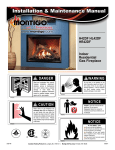
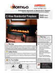
Installation & Maintenance Manual
R320 Indoor R420 Indoor
R-Series
Residential
Fireplace
DANGER
Read and understand this manual.
Improper installation, adjustment,
alteration, service or maintenance
can cause serious injury, property
damage or even death. For
assistance or additional information
consult a qualified installer, service
agency or the gas supplier.
WARNING
Do not store or use gasoline or any
other flammable vapors and liquids in
the vicinity of this or any other gas
burning appliance. A fire or explosion
my occur causing serious injury,
property damage or even death.
XW2006
XW2002
NOTICE
CAUTION
Glass doors on gas fireplaces are
extremely hot while the fireplace is
on and remain hot even after the
fireplace has been turned off. Safety
screens are available and can reduce
the risks of severe burns. Please
keep children away from the fireplace
at all times.
Installer: Leave this manual with the
appliance. Do not remove.
Consumer: Retain this manual for
maintenance and future reference. Do
not Discard.
XW2012
XW2004
NOTICE
Blank
IF YOU SMELL GAS
Do not try to light any appliance.
Do not touch any electrical switch; do
not use any phone in your building.
Immediately call your gas supplier
from a neighbor's phone. Follow the gas
supplier's instructions.
If you cannot reach your gas supplier,
call the fire department.
Blank
Flammable materials
Toxic
Corrosive
Danger overhead crane
Flammable materials
Explosion risk
Toxic
Corrosive
Danger overhead crane
Fork lift trucks
High voltage
General Warning
Laser Radiation
Explosion risk
Biohazard
Oxidising
Hot surface
Danger of entrapment
Fork lift trucks
Danger of death
High voltage
Laser Radiation
Biohazard
Oxidising
Hot surface
Danger of entrapment
Danger of death
Slippery floor
Watch your step
Glass hazard
Danger of suffocation
Blank
General Warning
Irritant
Flammable materials
Irritant
®
Watch your step
Cutting
High temperatures
Electricity
Danger for cutter
Entrapment hazard
Battery hazard
Rotating parts
Biohazard
Oxidising
Hot surface
Danger of entrapment
Danger of death
Watch for
falling objects
Electricity
Danger for cutter
Strong magnetic field
Optical radiation
Non ionizing
radiation
Blank
Gas bottles
US
High temperatures
Danger overhead crane
Toxic
Slippery floor
Watch for
falling objects
Laser Radiation
Low temperature
C
Cutting
Corrosive
Explosion risk
Gas bottles
General Warning
Fork lift trucks
High voltage
Glass hazard
Danger of suffocation
Entrapment hazard
Battery hazard
Radiation
Hazardous to the
Environment
Danger of harming
your hands
Glass hazard
Danger of suffocation
Fork lift trucks
Hazardous to the
Environment
High voltage
Danger of harming
your hands
Irritant
Slippery floor
Watch your step
Cutting
High temperatures
Flammable materials
Low temperature
Explosion risk
Strong magnetic field
Toxic
Optical radiation
Corrosive
Non ionizing
radiation
Danger overhead crane
Radiation
Electricity
Danger for cutter
Entrapment hazard
Battery hazard
Gas bottles
Watch for
falling objects
Rotating parts
Rotating parts
General Warning
Laser Radiation
Biohazard
Oxidising
Hot surface
Danger of entrapment
Low temperature
Strong magnetic field
Optical radiation
Non ionizing
radiation
Radiation
Hazardous to the
Environment
Danger of harming
your hands
Irritant
Slippery floor
Watch your step
Cutting
High temperatures
Glass hazard
Danger of suffocation
Danger of death
XW2014
XG0770
Canadian Heating Products Inc. Langley, BC V4W 4A1 | Montigo Del Ray Corp. Ferndale, WA 98248
020911
R-Series R320-R420 Indoor Gas Fireplace
NOTICE
You must read and understand this
manual prior to installation, operation or
troubleshooting this appliance. Please
retain this owner’s manual for furure
reference and maintenance.
XW2010
Table of Contents
Instruction Manual Contents
Safety Alert Key............................................................. 3
Introduction . ................................................................. 3
Congratulations on your purchase.................................. 3
Installation Of Electrical Supply..................................... 17
Installing The Remote Switch........................................ 17
Section 4: Wiring............................................................... 17
HSI Wiring Schematic................................................... 18
Conduit & Wiring clearances ........................................ 18
Warranty and Installation Information: (See Appendix B).3
IPI Wiring Schematic..................................................... 19
Installation . ................................................................. 4
Fuel Consumption......................................................... 20
Section A: Before You Begin .......................................... 4
Pressure requirements:................................................. 20
Important Message...................................................... 4
Gas Connection............................................................ 20
Save these Instructions............................................... 4
Section 5: Installing the Gas Line .................................... 20
Before you start............................................................... 4
Fireplace Facing............................................................ 21
Pre-Installation Checklist............................................. 4
Mantels & Surrounds................................................. 21
Understanding the Basic Operation............................. 4
Section 6: Finishing ......................................................... 21
Residential R320-ST & R420-ST fireplace.................. 4
The R-Series R320-ST & R420-ST fireplaces................. 5
Fireplace dimensions.................................................5
Clearances.................................................................. 5
Section 1: Installation Overview & Product Dimensions. 5
Section 2: Framing.......................................................... 6
Installing a Roof Mounted Power Vent........................ 9
Venting Layout............................................................. 9
Straight Venting Layout............................................ 9
Multi-Elbow Installations.......................................... 9
Downward Vertical Venting...................................... 9
Section 3: Installing the Power Vent . ............................. 9
Venting Components................................................. 10
Installation of the External roof mounted power vent..10
Removing the doors:..................................................... 22
Section 7:Removing & Installing the Door ....................... 22
Installing the Door:........................................................ 22
Section 8: Installing the Firestones .................................. 23
Optional River Rocks.................................................... 23
Operation . ............................................................... 24
Section 9: Start-up Sequence .......................................... 24
Honeywell Intermittent Pilot........................................... 24
For Your Safety - READ BEFORE LIGHTING........... 24
Lighting Instructions....................................................... 25
General . ............................................................... 25
Cleaning . ............................................................... 25
Burner Adjustment............................................................ 25
Gas Control Valve............................................................. 25
Section 10: Cleaning and Maintenance............................ 25
Installing the external roof mounted power vent module.. 11
Appendix A . ............................................................... 26
Installing a Wall Mounted Vertical Exterior Power Vent.13
Power Vent Locations....................................................... 26
Venting Layout........................................................... 13
Vertical Power Vent Detail............................................. 27
Multi-Elbow Installations........................................ 13
Horizontal Power Vent Detail........................................ 27
Downward Vertical Venting.................................... 13
Appendix B . ............................................................... 28
Venting Components................................................. 14
Warranty . ............................................................... 28
Installation of the external wall mounted power vent.14
Appendix C . ............................................................... 29
Installing the external wall mounted power vent module.15
State of Massachusetts.................................................... 29
Page 2
XG0770 - 020911
R-Series R320-R420 Indoor Gas Fireplace
Safety Alert Key
DANGER
WARNING
Indicates a hazardous situation which, if not
avoided, WILL result in death or serious
injury or property damage.
Indicates a hazardous situation which, if not
avoided, COULD result in death or serious
injury or property damage.
CAUTION
NOTICE
Indicates a hazardous situation which, if not
avoided, WILL result in minor or moderate
injury.
Address practices that are important, but
not related to personal injury
Introduction
INTRODUCTION
Warranty and Installation Information: (See Appendix B)
Congratulations on your purchase of a Montigo Fireplace.
With over 30 years of experience, Montigo is committed
to providing you with a gas fireplace that is not only a
beautiful addition to your space, but that is also designed
and manufactured to the highest safety, reliability and
engineering standards.
We strongly encourage you to read and carefully follow
the instructions laid out in this Installation, Operation and
Maintenance Manual and retain it for your future reference.
Pay special attention to all cautions, warnings, and notices
throughout this manual intended to ensure your safety.
This manual covers installation, operation and maintenance.
Lighting, operation and care of this fireplace can be easily
performed by the homeowner. All installation and service
work should be performed by a qualified or licensed installer,
plumber or gas fitter as certified by the state, province, region
or governing body where the fireplace is being installed.
The Montigo warranty will be voided by, and Montigo
disclaims any responsibility for, the following actions:
► Modification of the fireplace and/or components
including Direct-Vent assembly or glass doors.
► Use of any component part not manufactured or
approved by Montigo in combination with this Montigo
fireplace system.
► Installation other than as instructed in this manual.
Consult your local Gas Inspection Branch on installation
requirements for factory-built gas fireplaces. Installation &
repairs should be done by a qualified contractor.
Blank
Flammable materials
General Warning
This installation, operation and maintenance manual is
applicable to the models described below. Refer to your
rating plate to verify included options.
Explosion risk
Toxic
Corrosive
Danger overhead crane
warning
Laser Radiation
Biohazard
Oxidising
Fork lift trucks
Hot surface
Danger of entrapment
Hot glass will cause
burns.
Do not touch
glass until unit is cooled.
Never allow children to
touch glass.
Irritant
Slippery floor
Watch your step
Cutting
High temperatures
Glass hazard
Gas bottles
Watch for
falling objects
Electricity
Danger for cutter
Entrapment hazard
Battery hazard
Low temperature
Strong magnetic field
Optical radiation
Non ionizing
radiation
Radiation
Hazardous to the
Environment
Fireplace BTU/H Input
XG0770 - 020911
Model#
Natural Gas
Propane
Venting Type
Burner Type
Ignition Type
R-Series R320
50,000
40,000
Top Dedicated Power Vent
Linear Burner
SIT Electronic Ignition (IPI)
R-Series R420
65,000
55,000
Top Dedicated Power Vent
Linear Burner
SIT Electronic Ignition (IPI)
Page 3
High volt
Danger of
Danger of suf
Rotating p
Danger of h
your han
R-Series R320-R420 Indoor Gas Fireplace
Installation
Section A: Before You Begin
Section:
Important Message Save these Instructions
The R-Series Residential R320 & R420 Power Vent
fireplaces must be installed in accordance with these
Instructions. Carefully read all the Instructions in this
manual first. Consult the Local Gas Branch to determine
the need for a permit prior to starting the installation. It is
the responsibility of the installer to ensure this fireplace is
installed in compliance with the manufacturers instructions
and all applicable codes.
NOTICE
Installation and repairs should be done by an
authorized gas fireplace service technician. The
appliance should be inspected before use and at
least annually by a professional. More frequesnt
cleaning may be required due to exessive lint from
carpeting, bedding material, ect. It is imperative
that control compartments, burners and circulating
air passageways of the fireplace are kept clean.
■Select your type and location of your Power Vent
run: Roof Mounted (EDVRSPV58) or Wall Mounted
(EDVWSPV58).
■Your termination location should be selected to provide
the shortest possible vent run.
■Lay out the Vent run; calculating the required elbows
and straight runs of 5"/8" flex or rigid pipe.
■Refer to the Section 3, "Installing the Power Vent"
for details.
■The electrical panel is located on the lower right side
when facing the fireplace.
■Montigo supplies 20' of low voltage wire, which can
be spliced to any length. This wire CANNOT run in
conduit with any other wire.
■Refer to Section 4, Wiring for Details.
■The gas connection is located on the lower end when
facing the fireplace.
■Refer to local codes and guidelines for installation
requirements.
■Installation and repairs should be done by a qualified
contractor and must conform to:
XW2016
CAUTION
Due to high operating temperatures, this appliance
should be located out of traffic & away from
furniture and draperies.
Children and adults should be alerted to the
hazards of the high surface temperature, which
could cause burns or clothing ignition.
Young children should be carefully supervised
when they are in the same room as the appliance.
Clothing or other flammable materials should not
XW2020-When-Installed_[EN].pdf
1
1/24/2011
12:48:53 PM
be placed on or near the appliance.
Blank
Flammable materials
Explosion risk
Toxic
Corrosive
Danger overhead crane
Fork lift trucks
High voltage
General Warning
Laser Radiation
Biohazard
Oxidising
Hot surface
Danger of entrapment
Danger of death
Watch your step
Danger of suffocation
Blank
Irritant
Slippery floor
Cutting
High temperatures
Glass hazard
Flammable materials
Explosion risk
Toxic
Corrosive
Danger overhead crane
Fork lift trucks
Gas bottles
Watch for
falling objects
Electricity
Danger for cutter
Entrapment hazard
Battery hazard
Rotating parts
General Warning
Laser Radiation
Biohazard
Oxidising
Hot surface
Danger of entrapment
Danger of death
Low temperature
Strong magnetic field
High voltage
Blank
Optical radiation
Non ionizing
radiation
Radiation
Explosion risk
Toxic
Corrosive
Danger overhead crane
Fork lift trucks
High voltage
Irritant
Slippery floor
Watch your step
Cutting
High temperatures
Glass hazard
Danger of suffocation
General Warning
Laser Radiation
Biohazard
Oxidising
Hot surface
Danger of entrapment
Danger of death
Electricity
Flammable materials
Gas bottles
XW2018
Watch for
falling objects
Hazardous to the
Environment
Danger of harming
your hands
Danger for cutter
Entrapment hazard
Battery hazard
Rotating parts
Irritant
Slippery floor
Watch your step
Cutting
High temperatures
Glass hazard
Danger of suffocation
Low temperature
Strong magnetic field
Optical radiation
Non ionizing
radiation
Radiation
Hazardous to the
Environment
Danger of harming
your hands
Gas bottles
Watch for
Electricity
Danger for cutter
Entrapment hazard
Battery hazard
Rotating parts
• Installations in the USA must conform to local
codes, or in the absence of local codes to the
National Fuel Gas Code, ANSI Z223.1-1988.
• See Appendix C for installation within the State
of Massachusetts. This fireplace must comply
with NFPA-54 Chapter 10.
DANGER
When this appliance is installed directly
on any combustible material other than
wood flooring, it must be installed on a
metal or wood panel extending the full
width and depth of the appliance or a
fire will occur causing serious injury,
property damage or even death.
XW2020
BEFORE YOU START:
Pre-Installation Checklist
■Determine the desired install location of your fireplace.
■See Section 1, Dimensions on Page 5, and refer to
the Framing Section 2 for details.
Page 4
• Installations in Canada must conform to the
current CAN/CGA B-149.1 and .2 Gas Installation
Code and local regulations.
■Refer to Section 5, "Installing the Gas Line" for Details.
Understanding the Basic Operation
Residential R320 & R420 fireplace
The control compartment of this fireplace is located in the
bottom of the fireplace right below the burner system. All
models will be supplied with a Honeywell smart valve gas
control and will not have a variable flame control. There
are two air switches that are controlling the gas control
system, and are located in the bottom of this fireplace.
These gas valves, and pressure switches communicate
with the electrical control panel via a six conductor cable
supplied with the fireplace.
To operate the fireplace, Montigo has supplied and installed
twenty feet of low voltage wire to this electrical control
panel. Connect the two wire harness to a standard single
pole ON/Off switch located at a location of your choice.
You may also extent these wires to any length, as long as
you select a wire of equal quality.
XG0770 - 020911
R-Series R320-R420 Indoor Gas Fireplace
Installation
Section 1: Installation Overview and Product Dimensions
WARNING
DANGER
The C-View Residential R320 & R420 are power vented fireplace systems. Under no
circumstances can these model(s) be installed without a power vent module.
For regular Horizontal vent installation use 5"/8" model EDVWSPV58 with the rough-in kit,
EDVWSPV58F for the R320 & R420.
For regular Vertical vent installation use 5"/8" model EDVRSPV58 with the rough-in kit,
EDVRSPV58F for the R320 & R420.
When this appliance is installed directly on any combustible material other than wood
flooring, it must be installed on a metal or wood panel extending the full width and
depth of the appliance or a fire will occur causing serious injury, property damage or
even death.
Dimensions
Clearances
The fireplace dimensions are shown below and on the
following page:
To ensure the R-Series Residential Fireplace operates
safely, all models must maintain the following clearances.
A
C
D
E
Top - Rear Vent *
Top - Top Vent
Back
Sides
Floor
Mantel **
B
R320
R420
10"
10”
2"
10"
10”
2"
3”
0"
6"
3”
0"
6"
* See Instructions on page 4, (figure 1a)
** See Instructions on page 16, (Mantels & Surrounds)
Unprotected combustible walls which are perpendicular to
the fireplace opening, must not be closer to the fireplace
than the described in Figure 16.
Front View
F
G
**27”
See Fig. 16
Exterior wall
framing
H
Top View
Min
6”
I
EPVRWF rough
-in Frame
Exterior
EPVRW
Power Vent
L
K
J
Exterior
Sheating
M
Exterior
Finishing
Material
N
Side View
Unit Dimensions
A
B
C
D
E
K
L
M
N
R-Series R320 48¹¹/₁₆" 38¹/₁₆"
19¾"
16⅛"
37¼" 24⁵/₁₆"
F
9½"
G
41⁹/₁₆" 15³/₁₆" 31¹⁵/₁₆"
H
I
J
5"
8"
12⅜"
5⅞"
R-Series R420 60¹¹/₁₆" 38¹/₁₆"
19¾"
16⅛"
49¼" 30⁵/₁₆"
9½"
53⁹/₁₆" 15³/₁₆" 31¹⁵/₁₆"
5"
8"
12⅜"
5⅞"
Figure 1. R-Series Residential Fireplace dimensions.
XG0770 - 020911
Figure 1a. R-Series Residential Rear clearance
dimensions.
Page 5
R-Series R320-R420 Indoor Gas Fireplace
Installation
Section 2: Framing
Section:
Step 1. To ensure your glass viewing area is at the optimum
height, follow the Example below, Figure 2. Example: If you
wish to have the bottom edge of the glass to be 24", the
Q (Opening)
top of the platform will be 8 7/8", ( 24"- 15 1/8" = 8 7/8" ).
This dimension takes in account the height of the
platform, plywood and adequate clearances.
U
Drywall
or Equivelant
Framing Dimensions
Model#
Q
R
U
R-Series R320
55"
47"
**23¾"
R-Series R420
67"
47"
**23¾"
R (Opening)
both sides
typical
** See Figure 1
¾"
Plywood
Platform
Figure 2. Fireplace installation, (Rough Frame-In dimensions) Both Sides are Typical.
Step 2. Place the Fireplace on the platform and install the
and provide a gas service shut-off valve; according to local
Vent pipe, and Power Vent module. (Install the module in
gas codes. Before fastening in place Line up the front face
a location where it can be accessed when the surround is
and rear face of the fireplace (top and bottom), Figure 2a.
installed around the fireplace). Next, Connect the Gas line,
then secure in place with 1/4" wood screws.
3" clearance to combustibles
RHS101 (up to 6')
around the exhaust pipe
Installed on top of firestop
when using firestop
Intake / Exhaust
Venting
½"
Supply Gas
connection
Figure 2a. Fireplace installation, (Inlet Gas & Power Vent) .
Step 3. Back-framing the Fireplace; installing 2 x 4's,
(Typical Both sides).
Ensure you have the required 2 x 4's to complete the project.
Cut Two (2) - 2 x 4's to fit under the front & rear fireplace
Page 6
throat, (horizontal), fit & remove. Next, cut the short 2 x
4's, to fit at each end under the previous Horizontals'. (Note:
when these pieces are secured into place there should be the required
1" clearance to combustibles), Figure 2b.
XG0770 - 020911
R-Series R320-R420 Indoor Gas Fireplace
Installation
NOTE: Remember, both sides of the Fireplace require the
same quantities of wood, drywall and hardware.
Next, cut the Required Left and Right Vertical 2 x 4's in
accordance with Figure 2b.
Cut the Upper and Lower Horizontal 2 x 4's in accordance
with Figure 2b. Next, cut the Required quantity of short filler
2x4's under the lower Horizontal. The number of pieces
will be determined by the length, and model of fireplace.
(Follow Typical building codes and practices when spacing).
Lastly, install the Two (2) Supplied Steel Headers 1" above
the fireplace throats. NOTE: When this assembly is
in place, ensure ALL the required 1" clearance to
combustibles are maintained.
Non-combustible Header
(Supplied by Montigo)
2 X 4, (Top
Horizontal)
2 X 4, (Bottom
Horizontal)
Space supplied Non-Combustable
Header to allow 6” of Cement
board to be fastened to
2-pcs 2 x 4, (vertical)
Both Sides Typical
First wood stud
installed at 18”
from top of glass
1"
Clearance
1"
Clearance
2 X 4 fillers,
(Vertical) use
typical
building
practices
when
spacing
1” Clearance
1" Clearance
Figure 2b. Fireplace installation, (Ensure you maintain the 1" clearance to combustibles) Both Sides are Typical.
Step 4. As shown in Figure 2c; Cut a sheet of Noncombustible Concrete Board to overlap the new 2 x 4's and
Non-combustible Header (front & rear face) See Figure 2b.
Place the Non-combustible wall board above the fireplace
Sheet metal screws to attach Non-Combustible
Cement board to Steel header, (supplied by Montigo)
throats, allowing 1/8" clearance from the rim above the
fireplace opening. Pre-drill pilot holes in the board with ⅛"
drill, secure to wood framing with Nails and use flat heat
sheet metal screws to fasten the board to the metal header.
Non-Combustible cement board,
(Supplied by Montigo) or Equivalent
Pre-drill for sheet
metal screws to
fasten cement
board to framing
⅛"
6"
Height
Clearance required for
expansion of the fireplace
when in operation
Figure 2c. Non-combustible Board over the Fireplace, (supplied by Montigo) Both Sides are Typical.
XG0770 - 020911
Page 7
R-Series R320-R420 Indoor Gas Fireplace
Installation
Step 5. As shown in Figure 2d; Cut standard Gyproc /
Drywall board to complete the installation of Both surrounds.
Fit the edges of the board to the rim around both fireplace
openings. Fasten the boards in place using standard
drywall screws.
Combustible Wallboard / Gyproc
or Equivelant (Top, Bottom & Sides)
Figure 2d. Fireplace installation (Cut the remainder of Gyproc / Wall board to complete the fireplace surrounds) Both Sides are Typical.
As shown in Figure 2c; Pre-drill the Non-combustible
Cement Board with an 1/8" drill, secure to framing with
Nails and use flat heat sheet metal screws to fasten the
board to the metal header.
Fasten Cement
Board to NonCombustable
Header using
Sheet Metal
Screws
Figure 2e. Fireplace installation (Pre drill pilot holes with 1/8" drill and attach Cement Board to Non-combustible Header using Sheet metal
Screws). Both Sides are Typical.
Page 8
XG0770 - 020911
R-Series R320-R420 Indoor Gas Fireplace
Installation
Section 3: Installing the Power Vent
Montigo supplies a variety of power venting options. The
location of the power vent should be selected and laid out
to provide the shortest possible run to an external wall or
through the roof. In the event that the external power vent
is not aesthetically acceptable or otherwise infeasible, an
in-line power vent can be utilized.
Multi-Elbow Installations
Multi-elbow installations are possible up to a maximum of
six 90° elbows.
V3
Section 3-1: Installing a Roof Mounted Vertical
Exterior Power Vent (EDVRSPV58)
Elbow 4
This section applies to installations where the shortest
possible vent run is through the roof. Refer to Appendix
A - Power Vent locations, to ensure the planned Power
vent location is acceptable. Once the vent location has been
established, please refer to the appropriate section below
for installation details.
Elbow 5
H2
V2
Elbow 2
Elbow 3
H1
V1
Section 3-1-1: Venting Layout
Straight Venting Layout
Elbow 1
Selection of components and details of venting lay out
should adhere to the following guidelines:
■Ensure there is a minimum run of 2’ of straight pipe
before the power vent
■Ensure the maximum vent run does not exceed 80’
■Ensure the number of 90° elbows does not exceed 6
■Ensure the number of 45° elbows does not exceed 12
Multi Elbow - Venting Installation
V1 + H1 + V2 + H2 + V3
(Maximum Length)
Max. # Elbows Elbow Angle
80 Feet
6
90°
Figure 3a. Multi-elbow Venting Installations.
Downward Vertical Venting
Note: The downward vent run must not exceed 6' of vent run.
V
Venting Installation
V (Maximum Length)
80 Feet
Max. # Elbows Elbow Angle
6
90°
Elbow 3
Elbow 2
H1
D = 6’ foot
MAX
V1
Figure 3. Typical straight Venting Installations.
V3
Elbow 1
Elbow 4
H2
Elbow
Multi Elbow - Venting Installation
V1 + H1 + V2 + H2 + V3
(Maximum Length)
40 Feet
Max. # Elbows Elbow Angle
6
90°
Figure 3b. Downward Venting Installations.
XG0770 - 020911
Page 9
R-Series R320-R420 Indoor Gas Fireplace
Installation
Section 3-1-2: Venting Components
The following venting components and associated Montigo
part numbers are available for the EDVRSPV58:
A - Termination
EDVRSPV58
B - Rough-in Frame
EDVRSPV58F
PFL-1 (12" Section)
PFL-2 (24" Section)
PFL-3 (36" Section)
PFL-4 (48" Section)
C - Flex Sections
D - Rigid Sections
PEXT - 1 (12" m/f Section)
PXT-20 (20" section)
PEXT - 2 (24" m/f Section)
PEXT - 3 (36" m/f Section)
PEXT - 4 (48" m/f Section)
E - Elbows
PEL-90MM (m/m 90° Elbow)
PEL-90FF (f/f 90° Elbow)
PEL-90FM (f/m 90° Elbow)
PEL-45FM (f/m 45° Elbow)
F - Power Cord
Harnesses:
EPVH10 -10 foot power cord and harness
EPVH20 -20 foot power cord and harness
EPVH30 -30 foot power cord and harness
EPVH40 -40 foot power cord and harness
EPVH50 -50 foot power cord and harness
EPVH60 -60 foot power cord and harness
EPVH70 -70 foot power cord and harness
EPVH80 -80 foot power cord and harness
EPVH90 -90 foot power cord and harness
EPVH100 -100 foot power cord and harness
Section 3-1-3: Installation of the EDVRSPV58
External roof mounted power vent module.
Refer to Appendix A - Power Vent locations, to ensure the
planned Vertical Power vent location is acceptable.
The EDVRSPV58 Power Vent dimensions:
Ø14”
19 1/4”
2”
8 1/2”
Ø 1/2”
Front View
18”
18”
Connection and installation of the vent components
should adhere to the following guidelines:
Top View
The EDVRSPV58F Rough-in Frame dimensions:
■Connect all vent sections using a minimum of three
sheet metal screws on the outer pipe flue.
■Ensure the pipe ends male to female slide in a
minimum of 1 1/2“ of overlap.
■Ensure all runs are supported with a minimum of
3 supports per 10’ of venting.
■When hanging/ supporting venting, ensure that
1” clearance is maintained on all sides to any
combustible material.
■Ensure when cutting sections of rigid pipe to maintain
integrity of internal supports.
■Place the springs, supplied with the pipe kit, between
the outer and inner pipes to keep the pipes separate
and avoid any possible hot spots.
■Montigo recommends the use of a flex section for the
final pipe connected directly to the fireplace offering
greater flexibility of installation and absorption of
movement.
■All exterior joints in venting should be sealed with
high heat silicone RV230.
6”
Ø 8”
14”
Front View
18”
18”
Top View
Page 10
XG0770 - 020911
R-Series R320-R420 Indoor Gas Fireplace
Installation
Installing the external roof mounted power vent module
Step 1.Construct a Vertical Chase for the termination
opening to meet the following requirements:
■Opening Size must be: 14 1/2" x 14 1/2" x 18" Min. height.
14½"
Step 3.Install the Power Vent Rough-in Kit. Pull wire
harness through the supplied hole in the bottom corner
of the rough-in box, and snap into the slot provided, (See
figure 4b inset).
Power Vent
Rough-in Kit
14½"
Electrical Harness
Connerctor Location
18"
Electrical
Harness
Figure 4. Construction, Rough-in framing.
Figure 4b. Installation of Rough-in Kit
Step 2.Install the Vent pipe female end up, and 2" to 3"
MAX. from the top of the Constructed Chase. Also, at this
point install the Electrical harness, (EPVH-(10-100) that will
communicate with the Power Vent Module.
2" to 3" Max.
Step 4.Install fasteners around perimeter of Rough-in Kit.
(Holes supplied for ease of installation)
Electrical Harness
with connection
Vent Pipe
Install Fasteners around
perimeter of Rough-in Kit
Vent Chase
Figure 4c. (Fasten Rough-in Kit to framing)
Figure 4a. Installation, Vertical Vent pipe. (female end top end).
WARNING
All venting material must be sealed with high heat
silicone sealant RV230. All venting material to be
Montigo flex pipe, with as few joints as possible.
All joints use MVA vent splice, sealed thoroughly
with silicone. Montigo will not be held responsible
for any water damage that may occur from not
installing the equipment as specified by this
document.
XW2024
XG0770 - 020911
Figure 4d. (Installed Stainless steel cover)
Page 11
R-Series R320-R420 Indoor Gas Fireplace
Installation
Step 5.Install the Power Vent, Roof-top Stainless steel
cover over the Installed Rough-in Kit. (You can see the
Electrical harness connector in the top right corner).
Electrical Harness
from Power Vent
Stainless Steel
Fasteners
Figure 4e.
Figure 4f.
Step 6.Install the Power Vent Module Power / communication
harness. Hold the Power Vent in close proximity of the
assembled Chase, (with stainless steel cover attached)
and plug in the Power Vent communication / Power Cord.
(Note the direction and orientation of the plug socket). (See
Figure 4e & Figure 4f)
Figure 4h. (Installed Power Vent Module)
Step 8.Install (3) three stainless steel fasteners around
Power Vent Module @120 degrees (penetrating through
the inner stainless steel vent cover)
Vertical Roof
Top
Power Vent
Install Power Vent
Module with Power
/ Communication
Harness
Vertical Roof Top
Power
Ve n t
Rough-in Kit
CAUTION
■ Vent terminations can be very hot. The
termination is to be installed higher than 7 feet
above a public walkway.
■ Do not obstruct, or attempt to conceal, the vent
termination. These actions will affect the operation
of the fireplace, and may be hazardous.
■ In heavy snow areas, take extra care to
prevent snow buildup from obstructing the vent
termination.
XW2026
CAUTION!
Vent terminations can be very hot. The termination is to be installed higher than 7 feet above a public walkw
Step 7.Install the Power
Vent
Module.orPlace
theto
Power
Do not
obstruct,
attempt
conceal, the vent termination. These actions will affect the operation of the fi
Vent Module over the
steel cover
and vent
stainless
In heavy snow
areas,flange
take extra
care to prevent snow buildup from obstructing the vent termination.
Figure 4g. (Installation of Power Vent Module)
pipe, aligning the Power Vent into final position. Ensure the
Harness is placed down in the Rough-in box when placing
the Power Vent Module into place. The Power Vent Module
will sit flush with the stainless steel cover if installed correctly.
Page 12
XG0770 - 020911
R-Series R320-R420 Indoor Gas Fireplace
Installation
Section 3-2: Installing a Wall Mounted Vertical
Exterior Power Vent (EDVWSPV58)
This section applies to installations where the shortest
possible vent run is through an exterior wall. Refer to
Appendix A - Power Vent locations, to ensure the planned
Power vent location is acceptable. Once the vent location
has been established, please refer to the appropriate section
below for installation details.
Multi-Elbow Installations
Multi-elbow installations are possible up to a maximum of
six 90° elbows.
Elbow 6
V3
Once the vent location has been established, please refer
to the appropriate section below for installation details.
Elbow 4
Elbow 5
Selection of components and details of venting lay out
should adhere to the following guidelines:
Elbow 2
■Ensure the number of 90° elbows does not exceed 6.
■Ensure the number of 45° elbows does not exceed 12.
Elbow 3
H1
■Ensure there is a minimum run of 2’ of straight pipe
before the power vent.
■Ensure the maximum vent run does not exceed 100’.
H2
V2
Section 3-2-1: Venting Layout
H3
V1
Elbow 1
H
Multi Elbow - Venting Installation
V1 + H1 + V2 + H2 + V3 = H3
Max. # Elbows Elbow Angle
(Maximum Length)
100 Feet
6
90°
Figure 5a. Multi-elbow Venting Installations.
V
Downward Vertical Venting
Note: The downward vent run must not exceed 6' of vent run.
H1
Venting Installation
V + H (Maximum Length)
100 Feet
Max. # Elbows Elbow Angle
6
90°
Figure 5. Typical Venting Installations.
V
D
WARNING
All venting material must be sealed with high heat
silicone sealant RV230. All venting material to be
Montigo flex pipe, with as few joints as possible.
All joints use MVA vent splice, sealed thoroughly
with silicone. Montigo will not be held responsible
for any water damage that may occur from not
installing the equipment as specified by this
document.
XW2024
XG0770 - 020911
H2
Multi Elbow - Venting Installation
V1 + H1 + D + H2
(Maximum Length)
40 Feet
Max. # Elbows Elbow Angle
6
90°
Figure 5b. Downward Venting Installations.
Page 13
R-Series R320-R420 Indoor Gas Fireplace
Installation
Venting Components
The following venting components and associated Montigo
part numbers are available for the EDVWSPV58:
A - Termination
EDVWSPV58
B - Rough-in Frame
EDVWSPV58F
PFL-1 (12" Section)
PFL-2 (24" Section)
PFL-3 (36" Section)
PFL-4 (48" Section)
C - Flex Sections
D - Rigid Sections
E - Elbows
F - Power Cord
Harnesses:
PEXT - 1 (12" m/f Section)
PXT-20 (20" section)
PEXT - 2 (24" m/f Section)
PEXT - 3 (36" m/f Section)
PEXT - 4 (48" m/f Section)
Installation of the EDVWSPV58 external wall
mounted power vent module.
Refer to Appendix A - Power Vent locations, to ensure the
planned Vertical Power vent location is acceptable.
The EDVWSPV58 Power Vent dimensions:
16¾"
14 ⅛"
PEL-90MM (m/m 90° Elbow)
PEL-90FF (f/f 90° Elbow)
PEL-90FM (f/m 90° Elbow)
PEL-45FM (f/m 45° Elbow)
14¾"
Side View
EPVH10 -10 foot power cord and harness
EPVH20 -20 foot power cord and harness
EPVH30 -30 foot power cord and harness
EPVH40 -40 foot power cord and harness
EPVH50 -50 foot power cord and harness
EPVH60 -60 foot power cord and harness
EPVH70 -70 foot power cord and harness
EPVH80 -80 foot power cord and harness
EPVH90 -90 foot power cord and harness
EPVH100 -100 foot power cord and harness
15⅝"
14⅛"
Connection and installation of the vent components
should adhere to the following guidelines:
■Connect all vent sections using a minimum of three
sheet metal screws on the outer pipe flue.
■Ensure the pipe ends male to female slide in a
minimum of 1 1/2“ of overlap.
■Ensure all runs are supported with a minimum of
3 supports per 10’ of venting.
■When hanging/ supporting venting, ensure that
1” clearance is maintained on all sides to any
combustible material.
■Ensure when cutting sections of rigid pipe to
maintain integrity of internal supports.
■Place the springs, supplied with the pipe kit, between
the outer and inner pipes to keep the pipes separate
and avoid any possible hot spots.
■Montigo recommends the use of a flex section for the
final pipe connected directly to the fireplace offering
greater flexibility of installation and absorption of
movement.
■All exterior joints in venting should be sealed with
high heat silicone RV230.
Page 14
Ø 5"
Front View
The EDVWSPV58F Rough-in Frame dimensions:
4⅝"
3"
Ø 8"
14"
Front View
18¾"
18¾"
Top View
XG0770 - 020911
R-Series R320-R420 Indoor Gas Fireplace
Installation
Installing the external wall mounted power vent
module
Step 1.Construct a frame for the termination opening to
meet the following requirements:
■Opening Size must be: 14 1/2" x 14 1/2".
Step 4.Insert the conduit from the Power Vent Module into
the rough-in frame through the two top right entry holes.
Remove the nut from the supplied strain relief and place
as shown, Figure 6c.
Strain Relief
14 1/2”
(Opening)
Power Vent Conduit
Strain Relief
Nut
14 1/2”
(Opening)
Figure 6. Framing the Opening for Power Vent
Figure 6c. Installation of Power Vent Conduit
Step 2.Insert the Power Vent Rough-in Box as shown in
Figure 6a. Fasten the Box securely in place with Screws
or nails, Figure 6a. Apply exterior sheathing and finishing
if required.
Step 5. Securely fasten bottom Collar pan into the Rough-in
frame using the existing hardware, (4-pcs). Tighten Strain
Relief nut onto Strain relief.
Framing
Fasteners
Step 6. Pull Power Vent Connector, (from behind) half-way
through supplied hole in conduit mounting frame, and snap
into place, (notches in two plastic wing clips. Orientation
not critical).
Strain Relief & tightened nut
Rough-in Frame
Power Vent Conduit
Conduit
mounting
frame
Power Vent
Connector
Figure 6a. Orientation, Placing the Power Vent Inner Box
Step 3.Next, remove the bottom collar and conduit mounting
frame as shown Figure 6b. (Place removed hardware in a
handy location for re-assembly).
Tightened hardware, 4-pcs.
Figure 6d. (Installing Conduit connector & conduit mounting frame)
Step 7.Fasten Conduit mounting frame into place using
existing hardware, (6-pcs). (Coil conduit in behind cover.)
Figure 6b. Installation of Rough-in Kit
XG0770 - 020911
Page 15
R-Series R320-R420 Indoor Gas Fireplace
Installation
Section:
Communication
Harness.
5” Inner Flue Collar, Typ.
All models (with gasket)
TOP of Power Vent,
(Note Quantity of
louvers).
8” Outer Flue Collar, R320,
R420 (with gasket)
5” Flue Cover Plate, Typ.
All models (with gasket)
Note louver
direction
8” Flue Cover Plate,
R320, R420 (with gasket)
Figure 5f. (Installation of Power Vent communication harness)
Step 9. Install the Power Vent. Place the Power Vent into the
Rough-in frame, aligning the Power Vent into final position.
Ensure the Harness is placed down in the Rough-in box when
placing the Power Vent. (Secure the Power Vent in Place with
the supplied hardware).
Figure 10. Flue cap installation, Top Vented fireplace.
Converting the Pressure Sensing tube from Top
vent to Rear vent
All R-Series Residential are shipped as Top vent fireplaces.
The fireplace will have installed a formed pressure
sensing tube. This tube which is installed at the factory is
manufactured from 1/4" aluminium tubing, Figure 11. It will
be required to remove the pre-installed 1/4" tube and Replace
with the supplied Rear vent tube / part as described below.
Tightened
hardware,
4-pcs.
Aim the pressure sensing tubing (Top Vent or Rear Vent) as
shown in Figure 11 to activate the control System. (Oval
below)
Figure 5g. (Completed Installation of Power Vent)
Top Vent
Opening
Converting to Top Vent / Rear Vent
All R-Series Residential are boxed and shipped as Top Vent
fireplaces. Should your installation specifications require that
you install your Vent system on the Rear of the fireplace,
read the following instructions carefully.
1.Remove the eight machine screws that secure the
10" cover plate to the rear vent take off location of the
fireplace. (Ensure you do not damage the fibre gasket)
2.Then, carefully Remove the 5" cover plate that is
installed on the inner rear vent take off location. (Ensure
you do not damage the fibre gasket).
3.Now, remove the Top vent (5" inner and 8" or 10" outer)
flue Collars. Switch the Collars and Cover plates as
shown in, Figure 10.
CAUTION!
When installing the Rear vent pressure sense tube, aim
into the rear vent opening the same way as pictured in
this installation, Figure 11. A loose fitting of the flare nut
will result in a malfunctioning or problematic fireplace
installation.
Page 16
Pressure sensing
tube, (Top Vent
configuration when
shipped). Replace
with the part for Rear
vent configuration.
Fitting installed
inside fireplace
Flare Nut on (Top
& Rear, pressure
sensing tubing, (do
not overtighten).
Rear Vent Opening
Replace tube from top vent configuration with Part supplied with the
fireplace for rear vent configuration.
Figure 11. Fireplace Air Proving switch tubing configuration.
Testing the System
The R-Series Residential Control and Power Vent System
can be safely tested prior to finish framing the Fireplace.
This test can be done quickly and efficiently to ensure all
systems function according to the design specifications.
The fireplace should be installed on the rough-in frame,
Figure 6a with the Power Vent Module and the Vent
Termination connected.
XG0770 - 020911
R-Series R320-R420 Indoor Gas Fireplace
Installation
Section 4: Wiring
Installation Of Electrical Supply
The R-Series Residential R320 & R420 Fireplaces are
supplied with an external electrical Control Panel pre-wired
by the factory. The power control box is connected to the
fireplace with a 20 foot long 6 conductor cable that will
communicate with the fireplace. The control panel should
be located in a location that would be accessible when the
fireplace in finished.
Wall Switch
110V Power Supply
Fuse
LED Indicator
6 - conductor
communication
cable
Power Vent
Speed Control
Left-sideView
Power Vent
Speed Control
Right-sideView
Figure 10. R-Series Residential Power Vent Module
Installing The Remote Switch
The R-Series Residential R320 & R420 Fireplaces may
be connected to a wall switch or a hand-held remote. The
valve operates on a 24V circuit. DO NOT connect the gas
Figure 8. (Fireplace to Control Panel Harness)
The power cord from the power vent module pugs into the
side of this panel. A 20 foot low voltage wire is attached
and connected to this panel as well. Connect a single pole
On/Off switch (Black and White) to these two wires at a
location of your choice, (See Installing the Remote Switch).
Installations in Canada must be electrically grounded in
accordance with CSA C22.1 Canadian Electrical Code Part
1 and/or Local Codes.
Installations in the USA must be electrically grounded in
accordance with local codes or, in the absence of local codes,
with the National Electrical Code, ANSI/NFPA 70-1987.
Pre-purge
Module
Power Vent
Motor
Indicator
light
Post-purge
Module
Wall Switch
Figure 11. (Remote Switch Wire connection)
valve to an external circuit.
The external electrical panel supplied with the fireplace is
equipped with a 20 foot low voltage wire, for connecting to
a wall switch of your choice. Should you require a longer
switch wire, replace this wire to any length with a wire of
equal quality. Additional length are available upon request.
CAUTION
Fuse
Vent Speed
Control
115V Power
Supply
The valve has a 1/2 minute Time-On Delay to
clear All possible build up of burned gas within
the System.
After this Time-On Delay the fireplace will
proceed with the Initiated Start-Up Sequence has
completed.
Wall
Switch
Gas Control
Wiring & Air
Proving
Switch
Ignitor
operation
Lights
XW2026
Terminal Block
Figure 9. (Control Panel Overview)
XG0770 - 020911
Page 17
R-Series R320-R420 Indoor Gas Fireplace
Installation
Section:
Pre-purge
Time-On delay
1
2
3
4
5
6
7
8
NC
Gas
Valve 1
LV Wall
Switch
Gnd
Green
Brn
Blu
Red
Blk / Wht
Wht / Blk
Blk / Wht
Wht / Blk
Post-purge Module
WARNING
If the information in these instructions is
not followed exactly, a fire or explosion
may result causing property damage,
personal injury or death.
NO
Combustion Flue Gas
Air Switch Switch
Fireplace
XW2008
Figure 21. R-Series Residential Wiring Schematic
Figure 21a. R-Series Residential SIT IPI Wiring Schematic
Page 18
XG0770 - 020911
R-Series R320-R420 Indoor Gas Fireplace
Installation
Section 5: Installing the Gas Line
Fuel Consumption
DANGER
Verify that your fireplace is compatible with your available gas type.
(Natural Gas or Propane shown by "N" or "L" in your model number
If gas type is not compatible, contact your local Montigo
representative to purchase a conversion kit.
After gas line is connected, each
appliance connection, valve and valve
train MUST be checked while under
normal operating pressure with either a
Liquid Solution, or Leak Detection
Device, to locate any source of leak.
Tighten any areas where bubbling
appears or a leak is detected until
bubbling stops completely or leak is no
longer detected. DO NOT use a flame
of any kind to test for leaks. A fire or
explosion will occur, causing serious
injusy, property damage or death.
Conversion kits must be installed by a qualified service
technician.
Gas Pressure
Optimum appliance performance requires proper input
pressures.
Gas line sizing requirements will be determined in ANSI
Z221.3 National Fuel Gas Code in the USA and CAN/CGA
B149 in Canada.
XW2030
Pressure requirements:
Pressure Requirements
Gas Pressure
Natural Gas
Minimum Inlet Pressure
5.5" W.C.
11" W.C.
Manifold Presure
3.5" W.C.
10" W.C.
NOTICE
Propane
When pressure testing the fireplace,
Gas line, and input system follow the
appropriate local codes or your area.
DO NOT connect the fireplace to
pressures in excess of 1/2lb. This will
damage the gas control valve.
The manifold outlet pressure is set from the factory to the
appropriate pressure but should be verified.
To check pressures, control valves have a provision to
remove a 1/8” N.PT. plug to be fitted with a hose barb.
Montigo requires a service shut off valve be located in an
accessible location to isolate the gas supply.
XW2032
Only install gas shut-off valves approved for use by the state,
province, or other governing body in which the fireplace is
being installed.
GAS CONNECTION
See Figure 14 below for location of gas line access.
Flexible gas connectors must not exceed 3 feet in length,
unless allowable within local regulations.
Connect incoming gas line to the 1/2"or 3/8" gas inlet port.
Purge all air out of gas line.
Check appliance connection, valve and valve train under
normal operating pressure with a commercially available
leak check solution.
DO NOT USE A FLAME OF ANY KIND TO TEST FOR
LEAKS.
3”
1/2” gas
3”
inlet
Figure 14. Gas Inlet Supply location, (Right-hand side of fireplace).
XG0770 - 020911
Page 19
R-Series R320-R420 Indoor Gas Fireplace
Installation
Section 6: Finishing
Combustible Construction
allowed in this area
Wood Header @ 18"
18
17
Drywall / Combustible
Construction allowed
in shaded area
Only Steel Stud construction
permitted within the grey area
Non-Combustible
Facing Material
Top of
fireplace
⅛" Clearance
to allow for
expansion
during
operation
Figure 16. Combustible mantles and facings. (Not to scale)
Fireplace Facing
Mantels & Surrounds
When selecting the finish material for your fireplace, it is
important to remember the following:
National Canadian Gas Association mantel test requirements
are for fire hazard prevention to combustible materials.
If the surround of the fireplace is to be painted to match
the room decor, heat-resistant paint must be provided .
Also, decorative facing must not extend past the fireplace
opening at all, because it will interfere with the access to
retainers for removal of glass door and access to the lower
compartment.
Please be aware; temperatures over the mantel will rise
above normal room temperature and walls above fireplace
may be hot to touch.
CAUTION
CAUTION
We recommend careful consideration
be given to the effects of elevated
mantel temperatures which may be in
excess of product design, for example:
candles, plastic or pictures. This can
cause melting, deformation, discoloration or premature failure of T.V. radio,
and other electronic components.
XW2034
Page 20
When covering the upper metal
portion of the fireplace, (as shown,
Fig.16) with a non-combustible
material, Please Note: The
decorative facing materials may
be subject to temperatures in
excess of 250° F. This should be
considered when selecting facing
materials.
XW2036
XG0770 - 020911
R-Series R320-R420 Indoor Gas Fireplace
Installation
Section 7:Removing & Installing the Door
Removing the doors:
The doors are removed in a few simple steps.
Follow the steps below to remove the Vertical Door trim,
place the Door removal tool, and then remove the door.
Replace all the parts in reverse order.
Step 1. Remove the two (2) Vertical Trim pieces, (LH &
RH). Pulling firmly with your fingers, remove from the bottom
then the top. (See Figures 17 & 17a). Other side Typical.
Step 3. Hold the Glass Removal Tools firmly, Lift the door
upward, into the top door frame, Figure 17c. Then pull the
bottom of the glass door downward, and tilt outward from
the bottom fireplace door frame. Figure 17d. NOTE: Read
ALL the instruction supplied with the tool, and follow the
associated operating procedures.
Lift Upward into
the door frame.
Lift Downward
& away from frame.
Figure 17c. (Lift the door
upward)
Figure 17d. (Lift the bottom
of the door outward).
Step 4. Still holding the Glass
Removal Tool firmly, remove the
door outward, and away from the
Fireplace, Figure 17e.
Step 5. Place the door in a safe
location while maintenance,
cleaning or other operation are
in progress.
Figure 17. (Remove LH Trim)
NOTE: Read ALL the
instruction supplied with the
tool, and follow the associated
operating procedures.
Figure 17a. (Remove RH Trim)
Step 2. Remove the supplied glass lifting tool from the
packaging. Place in the center of the Glass door as shown,
and activate the suction feature of the tool, Figure 17b.
NOTE: Read ALL the instruction supplied with the tool, and
follow the associated operating procedures.
Step 6. To replace, See Installing
the Door, Below.
Figure 17e.
Installing the Door:
To install the door, follow Steps 1 and 4 above, (in reverse
order).Hook the top edge of the door frame into place. Lower
and rest the door frame in place and fasten the buckles.
See figures 28a and 28b.
NOTICE
Do not use ammonia based or abrasive
cleaners on the glass, they will
permanently etch the surface. Use an
approved gas fireplace glass cleaner
such as Kel-Kem or White off.
Figure 17b. Supplied Glass lifting tools
XW2000
XG0770 - 020911
Page 21
R-Series R320-R420 Indoor Gas Fireplace
Installation
Section 8: Installing the Firestones
The R-Series Residential R320 & R420 fireplace have the
option of installing the supplied glass Firestones or other
optional colored glass media, or cultured rocks.
Note: The designer Firestones or cultured rocks cannot
cover the burners, doing so produces an undesirable /
uneven flame pattern and eventual sooting.
Firestones
Optional River Rocks
The R-Series Residential fireplace has the option of installing
the cultured rocks which mimic real stone. These may be
spaced at random, or in a visual pattern of your preference.
See the Montigo web site for photographs and ideas.
www.montigo.com
The R-Series Residential R320 & R420 fireplace are
supplied with a quantity of Glass Firestones. To install
the Firestones remove the Door and trim as shown in the
previous Instruction. Follow these instructions to ensure all
parts are removed or replaced as required. Once the Trim
and glass doors are removed place the firestones randomly
around the burners as shown in Figures 19 and 19a.
Note: DO NOT cover the burners with designer
Firestones or Optional Rocks.
NOTICE
Do not operate this fireplace without the
glass door or with a broken glass door.
XW2038
Figure 19. Completed glass Firestone installation. (Note: DO NOT place
glass Firestones on top of mesh pilot cover to complete the installation.
Figure 19a. Operating Propane gas fireplace with designer glass
Firestones surrounding burner tray.
Page 22
XG0770 - 020911
R-Series R320-R420 Indoor Gas Fireplace
Operation
Section 9: Start-up Sequence
WARNING
If the information in these instructions is
not followed exactly, a fire or explosion
may result causing property damage,
personal injury or death.
XW2008
Startup Sequence:
1) Turn the wall switch ON
all of the air out of the gas lines within the fireplace
2) The blowers will start and within 10 seconds the glow
plugs will start to glow
5) Turning the switch OFF and then ON again will reset
this start up sequence
3) If the pilot does not light the gas valves will turn the
glow plugs off after 20 seconds
6) Once the pilots are burning the main burner will turn
on and the fireplace will be functional for a quick start up
on next use.
4) This may need to be done three or four times to bleed
CAUTION
■ This fireplace has been set up at the factory for a
determined air volume though the venting system.
■ This fireplace will not operate unless the correct
air movement is detected by our control system..
■ Please consulted with your contact person at
Montigo should you have any problems with your
start up.
XW2040
Operation
Honeywell Intermittent Pilot
For Your Safety - READ BEFORE LIGHTING:
A.This appliance is equipped with an ignition system that
lights the pilot burner automatically. Do not attempt to
light the pilot by hand.
B.BEFORE LIGHTING smell all around the appliance
area for gas. Be sure to smell next to the floor because
some gas is heavier than air and will settle on the floor.
What To Do If You Smell Gas:
■ Do not try to light any appliance.
■Do not touch any electrical switch; do not use any phone
in your building.
XG0770 - 020911
■Immediately call your gas supplier from a neighbour's
phone. Follow the gas supplier's instructions.
■If you cannot reach your gas supplier, call the Fire
Department.
C.Do not use this appliance if any part has been under
water. Immediately call a qualified service technician
to inspect the appliance and to replace any part of the
control system, and any gas control which has been
under water.
Page 23
R-Series R320-R420 Indoor Gas Fireplace
Maintenance
Section 10: Cleaning and Maintenance
Lighting Instructions See pages 24
General
■Have the fireplace and installation inspected yearly.
The inspection must include, but is not limited to, the
following:
•A visual check of the entire vent system and
termination.
•An inspection of the explosion relief flappers and
the door gaskets to ensure a proper seal.
•An inspection of the burner, vent run, and primary
air openings.
• An inspection of the gas valve, gas components, and
pilot flame. For your convenience a 1/8" manifold
pressure tap is supplied on the gas valve for a test
gauge connection.
be visible. Film can easily be removed by removing the
door, as shown on Page 22. Handle the door carefully, and
clean it with non-abrasive glass cleaners. One of the most
effective products is Kel Kem.
■ Silicone seals on inner door during initial firing will
"off gas", leaving a visual deposit of a white substance on
combustion chamber walls. This can easily be removed
using normal household products.
■ Use a vacuum cleaner or whisk broom to keep the
control compartment, burner, and firebox free from dust
and lint. Gas Control Valve
Honeywell (Q3450)
Pilot Assembly
• Ensure proper log placement as per this manual.
Pilot Electrical
Harness Connector
•Inspection of all optional equipment; fans,
thermostats, etc.
■For Natural Gas this appliance requires a minimum
inlet pressure of 5.5" W.C. and a manifold pressure of
3.5" W.C.
■For Propane Gas this appliance requires a minimum
inlet pressure of 11" W.C. and a manifold pressure of
10" W.C.
Honeywell Gas
Control (SV9501M)
Gas Control
Connector
■Always keep the fireplace area clear and free of
combustible materials, as well as gasoline and other
flammable vapors and liquids.
■Do not use this appliance if any part has been under
water. Immediately call a qualified service technician
to inspect the appliance and to replace any part of the
control system and any gas control which has been
under water.
R
W
Bk
Figure 32. Gas valve.
Cleaning
When the fireplace is first activated, there may be some
smoking and a visible film may be left on the glass. This is
a normal condition, and is the result of burning of protective
coatings on new metal.
■ Glass must be cleaned periodically to remove any film
(which is a normal by-product of combustion) which may
NOTICE
Do not use ammonia based or abrasive
cleaners on the glass, they will
permanently etch the surface. Use an
approved gas fireplace glass cleaner
such as Kel-Kem or White off.
XW2000
Page 24
XG0770 - 020911
R-Series R320-R420 Indoor Gas Fireplace
Appendix
Appendix A: Power Vent Locations
V
Horizontal
Detail
A = clearance to the termination frame above grade, veranda,
porch, deck, or balcony [30 inches (75 cm) minimum]
B = clearance to door, or sides and top of window, that may be
opened [30 inches (75 cm) minimum for appliances.
C = clearance to bottom of window that may be opened horizontally
[36 inches (92 cm) minimum for appliances.
D = no clearance to permanently closed window when installed
with approved glass penetration termination
E = clearance to permanently closed window [30 inches 75 cm
recommended to prevent condensation on window]
F = vertical clearance to ventilated soffit located above the
termination within a horizontal distance of [30 inches 75 cm] from
the centreline of the termination [30 inches (75 cm) minimum]
G =c l e a r a n c e t o u n v e n t i l a t e d s o f f i t [ 3 0 i n c h e s
(75
cm)
minimum
to
n o n - c o m b u s t i b l e s ] .
[30 inches (75 cm) minimum to combustibles]
H = clearance to outside corner [30 inches (75 cm) minimum]
I = clearance to inside corner [30 inches (75 cm) minimum]
J = * not to be installed above a meter/regulator assembly within
40" (103 cm) horizontally from the centerline of the regulator
K = clearance to service regulator vent outlet [3 feet minimum in
the United States] [*6 feet (1.8 m) minimum in Canada]
L = clearance to non-mechanical air supply inlet to building or
the combustion air inlet to any other appliance [16 inches (41 cm)
minimum for appliances ≤100 000 BTU/H (30kW)]
M =clearance to mechanical air supply inlet [*6 feet (1.8 m)
XG0770 - 020911
Vertical Detail
minimum]
N = † clearance above paved sidewalk or a paved driveway located
on public property [*7 feet (2.1 m) minimum]
P = clearance under veranda, porch, deck, or balcony [30 inches
(75 cm) minimum‡ to non-combustibles] [30 inches (75 cm)
minimum‡ to combustibles]
Q =clearance above a roof [18 inches (46 cm) minimum]
R = clearance to adjacent walls and neighboring buildings [30
inches (75 cm) minimum]
S = clearance from corner in recessed location [30 inches (75
cm) minimum]
T = maximum depth in recessed location [48 inches (122 cm)
minimum]
U = minimum width for back wall of recessed location [60 inches
(150 cm) minimum]
V = minimum horizontal clearance between the frames of two
terminations that are level, (see applicable Detail).
W =horizontal clearance between the frames of two terminations
that are not level. [30 inches (75 cm) minimum]
a vent shall not terminate directly above a sidewalk or paved
driveway which is located between two single family dwellings and
serves both dwellings
†
‡
only permitted if veranda, porch, deck, or balcony has an open
side that is equal to or greater than the depth of the enclosed area
* as specified in CGA B149 Installation Codes. Note: local
Codes or Regulations may require different clearance.
Page 25
R-Series R320-R420 Indoor Gas Fireplace
Appendix
Appendix A: Pow er Vent Locations
EDVRSPV58 Vertical Power Vent Detail
EDVWSPV58 Horizontal Power Vent Detail
Wall
30”Min.
“R”
Eaves / Overhang
Wall
Wall
30”Min.
“R”
Top View
“R”
30”Min.
“H” & “I”
30”Min.
“F” & “G”
30” (75cm)
Min. “V”
Front View
24” (61cm)
Min. “V”
Wall
18”
18”
Min.
Front View
Eaves / Overhang
Wall
Not
Acceptable
Front View
Eaves / Overhang
Wall
Min 12"
Front View
Page 26
XG0770 - 020911
R-Series R320-R420 Indoor Gas Fireplace
Appendix
Appendix B: Warranty
The Warranty
The Companies warrants the Montigo Gas Appliance to be free from defects in materials and workmanship at the time of manufacture. On the Montigo fireplace,
there is a ten-year warranty on the firebox and its components, a five-year warranty on the main burner and pilot burner, and a one-year warranty on the gas control
valve, fibre logs and Power Vent Module. The Glass, plated / painted finishes, and refractory lining are exempt from the warranty.
Remedy And Exclusions
The coverage of this Warranty is limited to all components of the Gas Appliance manufactured by The Companies.
This Warranty only covers Montigo Gas Appliances installed in the United States or Canada.
If the components of the Gas Appliance covered by this Warranty are found to be defective within the time frame stated (see The Companies right of investigation
outlined below). The Companies will, at its option, replace or repair defective components of the Gas Appliance manufactured by The Companies at no charge,
and will also pay for reasonable labour costs incurred in replacing or repairing components. If repair or replacement is not commercially practical, The Companies
will, at its option, refund the purchase price of the Montigo Gas Appliance.
This Warranty covers only parts and labour as provided above. In no case shall The Companies be responsible for materials, components, or construction which
are not manufactured or supplied by The Companies, or for the labour necessary to install, repair or remove such materials, components or construction. All
replacement or repair components will be shipped F.O.B. the nearest The Companies factory.
Qualifications To The Warranty
The Gas Appliance Warranty outlined above is further subject to the following qualifications:
(1) The Gas Appliance must be installed in accordance with The Companies installation instructions and local building codes. The Warranty on this Montigo
Gas Appliance covers only the component parts manufactured by The Companies. The use of components manufactured by others with this Montigo Gas
Appliance could create serious safety hazards, may result in the denial of certification by recognized national safety agencies, and could be in violation of
local building codes. This warranty does not cover any damages occurring from the use of any components not manufactured or supplied by The Companies
(2) The Montigo Gas Appliance must be subjected to normal use. The Gas Appliances are designed to burn gas only. Burning conventional fireplace fuels such
as wood, coal or any other solid fuel will cause damage to the Gas Appliance, will produce excessive temperatures and will result in a fire hazard.
Limitations On Liability
It is expressly agreed and understood that The Companies sole obligation, and purchaser's exclusive remedy under this Warranty, under any other warranty,
expressed or implied, or in contract, tort or otherwise, shall be limited to replacement, repair, or refund, as specified above.
In no event shall The Companies be responsible for any incidental or consequential damages caused by defects in its products, whether such damage occurs
or is discovered before or after replacement or repair, and whether or not such damage is caused by The Companies negligence. Some states do not allow the
exclusion or limitation of incidental or consequential damages, so the above limitation or exclusion may not apply to you. The duration of any implied warranty
with respect to this Montigo Gas Appliance is limited to the duration of the foregoing warranty. Some states do not allow limitation on how long an implied warranty
lasts, so the above may not apply to you.
Investigation Of Claims Against Warranty
The Companies reserves the right to investigate any and all claims against this Warranty and to decide upon method of settlement.
The Companies Are Not Responsible For Work Done Without Written Consent
The Companies shall in no event be responsible for any warranty work done without first obtaining The Companies written consent.
Dealers Have No Authority To Alter This Warranty
The Companies employees and dealers have no authority to make any warranties nor to authorize any remedies in addition to or inconsistent with those stated above.
How To Register A Claim Against Warranty
In order for any claim under this Warranty to be valid, The Companies must be notified of the claimed defect in writing or by telephone, as soon as reasonably
possible after the defect is discovered. Claims against this Warranty in writing should include the date of installation, and a description of the defect.
Other Rights
This Warranty gives you specific legal rights, and you may also have other rights which vary from state to state.
NOTE:
The Companies as stated above refer to - Canadian Heating Products Inc. and/or Montigo Del Ray Corp.
Canadian Heating Products Inc. and/or Montigo DelRay Corp. reserves the right to make changes at any time, without notice, in design, materials,
specifications, prices and also to discontinue colors, styles and products.
XG0770 - 020911
Page 27
R-Series R320-R420 Indoor Gas Fireplace
Appendix C: State of Massachusetts
Appendix
Amendment
(Gas Fireplace / Equipment sold in the State of Massachusetts)
5.08: Modifications to NFPA-54, Chapter 10
(1) Revise NFPA-54 section 10.5.4.2 by adding a second exception as follows:
Existing chimneys shall be permitted to have their use continued when a gas conversion burner is installed, and shall be equipped with a manually reset device
that will automatically shut off the gas to the burner in the event of a sustained back-draft.
(2) Revise 10.8.3 by adding the following additional requirements:
(a) For all side wall horizontally vented gas fueled equipment installed in every dwelling, building or structure used in whole or in part for residential purposes,
including those owned or operated by the Commonwealth and where the side wall exhaust vent termination is less than seven (7) feet above finished grade in
the area of the venting, including but not limited to decks and porches, the following requirements shall be satisfied:
1. INSTALLATION OF CARBON MONOXIDE DETECTORS. At the time of installation of the side wall horizontal vented gas fueled equipment, the installing plumber or gas fitter shall observe that a hard wired carbon monoxide detector with an alarm and battery back-up is installed on the floor
level where the gas equipment is to be installed. In addition, the installing plumber or gas fitter shall observe that a battery operated or hard wired carbon
monoxide detector with an alarm is installed on each additional level of the dwelling, building or structure served by the side wall horizontal vented gas fueled
equipment. It shall be the responsibility of the property owner to secure the services of qualified licensed professionals for the installation of hard wired carbon
monoxide detectors
a. In the event that the side wall horizontally vented gas fueled equipment is installed in a crawl space or an attic, the hard wired carbon monoxide detector with
alarm and battery back-up may be installed on the next adjacent floor level.
b. In the event that the requirements of this subdivision can not be met at the time of completion of installation, the owner shall have a period of thirty (30) days
to comply with the above requirements; provided, however, that during said thirty (30) day period, a battery operated carbon monoxide detector with an alarm
shall be installed.
2. APPROVED CARBON MONOXIDE DETECTORS. Each carbon monoxide detector as required in accordance with the above provisions
shall comply with NFPA 720 and be ANSI/UL 2034 listed and IAS certified.
3. SIGNAGE. A metal or plastic identification plate shall be permanently mounted to the exterior of the building at a minimum height of eight (8) feet
above grade directly in line with the exhaust vent terminal for the horizontally vented gas fueled heating appliance or equipment. The sign shall read, in print
size no less than one-half (1/2) inch in size, “GAS VENT DIRECTLY BELOW. KEEP CLEAR OF ALL OBSTRUCTIONS”.
4. INSPECTION. The state or local gas inspector of the side wall horizontally vented gas fueled equipment shall not approve the installation unless,
upon inspection, the inspector observes carbon monoxide detectors and signage installed in accordance with the provisions of 248 CMR 5.08(2)(a)1 through 4.
(b) EXEMPTIONS: The following equipment is exempt from 248 CMR 5.08(2)(a)1 through 4:
1. The equipment listed in Chapter 10 entitled “Equipment Not Required To Be Vented” in the most current edition of NFPA 54 as adopted by the
Board; and
2. Product Approved side wall horizontally vented gas fueled equipment installed in a room or structure separate from the dwelling, building or structure used in whole or in part for residential purposes. (c) MANUFACTURER REQUIREMENTS - GAS EQUIPMENT VENTING SYSTEM PROVIDED. When the manufacturer of Product
Approved side wall horizontally vented gas equipment provides a venting system design or venting system components with the equipment, the instructions
provided by the manufacturer for installation of the equipment and the venting system shall include:
1. Detailed instructions for the installation of the venting system design or the venting system components; and
2. A complete parts list for the venting system design or venting system.
(d) MANUFACTURER REQUIREMENTS - GAS EQUIPMENT VENTING SYSTEM NOT PROVIDED. When the manufacturer of a Product Approved side wall horizontally vented gas fueled equipment does not provide the parts for venting the flue gases, but identifies “special venting systems”,
the following requirements shall be satisfied by the manufacturer:
1. The referenced “special venting system” instructions shall be included with the appliance or equipment installation instructions; and
2. The “special venting systems” shall be Product Approved by the Board, and the instructions for that system shall include a parts list and
detailed installation instructions.
(e) A copy of all installation instructions for all Product Approved side wall horizontally vented gas fueled equipment, all venting instructions, all parts lists for
venting instructions, and/or all venting design instructions shall remain with the appliance or equipment at the completion of the installation.
(3) After NFPA-54 section 10.10.4.2 add a new section 10.10.4.3 as follows:
When more than four gas appliances are to be vented through a common gas vent or common horizontal vent manifold, a plan of the proposed vent installation
shall be submitted to the Inspector and the serving gas supplier for review and approval.
Extraction from: Massachusets Rules and Regulations
5.00: Amendments To 2002 Edition Of ANSI Z223.1-NFPA-54
Page 28
XG0770 - 020911
R-Series R320-R420 Indoor Gas Fireplace
Notes
XG0770 - 020911
Page 29
R320 - R420
R-Series Residential ~ Gas Fireplace
Ferndale, Washington
TF: 1.800.789.6236
FX: 1.866.3000.0927
XG0770 - 020911
Langley, British Columbia
TF: 1.800.378.3115
FX: 1.604.607.6462