1
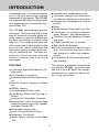
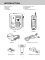
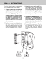
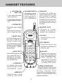
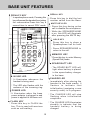
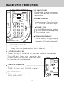
TABLE OF CONTENTS
INTRODUCTION...............................................................................................................3
Parts Check List:.................................................................................................................4
IMPORTANT SAFETY INSTRUCTIONS.........................................................................5
REPLACING THE HANDSET BATTERY...........................................................................7
SPARE BATTERY CHARGER............................................................................................8
GETTING STARTED............................................................................................................9
Setting Up Your VT9141.....................................................................................................9
WALL MOUNTING............................................................................................................10
HANDSET FEATURES..................................................................................................11
INT.COM/LOW BATT LED.............................................................................................11
PHONE KEY................................................................................................................11
TONE/* KEY..................................................................................................................11
HOLD KEY.....................................................................................................................11
PGM KEY.....................................................................................................................11
MEM KEY..................................................................................................................11
VOLUME SWITCH.........................................................................................................11
CHAN KEY..................................................................................................................11
HANDSET JACK.........................................................................................................11
OFF KEY.................................................................................................................11
INT.COM KEY..............................................................................................................11
PRV KEY..................................................................................................................11
REDIAL/PAUSE KEY.....................................................................................................11
BASE UNIT FEATURES................................................................................................12
PRIVACY KEY..............................................................................................................12
IN USE LED.............................................................................................................12
POWER LED................................................................................................................12
FLASH KEY..............................................................................................................12
REDIAL KEY...................................................................................................................12
MUTE KEY/LED..........................................................................................................12
HOLD KEY..................................................................................................................12
MEMORY KEY.................................................................................................................12
SPARE BATT LED..........................................................................................................12
CHARGE LED................................................................................................................12
VOLUME UP KEY......................................................................................................13
VOLUME DOWN KEY....................................................................................................13
TONE/* KEY................................................................................................................13
SPEAKERPHONE KEY................................................................................................13
SPEAKERPHONE LED................................................................................................13
INTERCOM KEY/LED....................................................................................................13
TONE/PLUSE SWITCH.................................................................................................13
RINGER SWITCH..........................................................................................................13
MAKING CALLS..............................................................................................................14
ANSWER A CALL.............................................................................................................15
TO PUT A CALL ON HOLD...........................................................................................15
THE MUTE FEATURE....................................................................................................15
1
TABLE OF CONTENTS
SWITCHING FROM BASE UNIT (SPEAKERPHONE) TO THE HANDSET...........16
SWITCHING FROM HANDSET TO THE BASE UNIT (SPEAKERPHONE)..........16
JOIN A CONVERSATION...............................................................................................16
PREVENT A THIRD PARTY FROM JOINING YOUR CONVERSATION...............17
USING THE INTERCOM.................................................................................................17
IF YOUR PHONE RINGS DURING AN INTERCOM CONVERSATION.................18
USING THE INTERCOM DURING A PHONE CALL.................................................19
TEMPORARY TONE FEATURE....................................................................................19
PROGRAMMING THE RINGER TYPE.........................................................................19
TURNING OFF THE RINGERS.....................................................................................20
CHECKING THE RINGER..............................................................................................20
MEMORY DIALING..........................................................................................................20
TO STORE A NUMBER INTO MEMORY......................................................................20
TO SPEED DIAL A STORED NUMBER......................................................................21
TO CHANGE OR REPLACE A STORED NUMBER....................................................21
STORING SPECIAL CODES AND PAUSES..............................................................21
USING REDIAL...............................................................................................................22
STORING A REDIAL NUMBER IN MEMORY DIAL...................................................22
TONE DEFINITIONS.........................................................................................................22
CHANGING CHANNELS...............................................................................................23
OPTIONAL HEADSET INSTALLATION AND OPERATING INSTRUCTIONS........23
MAINTENANCE...............................................................................................................25
IN CASE OF DIFFICULTY...............................................................................................26
WARRANTY STATEMENT...............................................................................................28
FCC AND IC REGULATIONS..........................................................................................30
TECHNICAL SPECIFICATIONS....................................................................................33
2
INTRODUCTION
Congratulations! You have purchased
one of the best performing cordless
telephones on the market! The VT 9141
is a single line 900 MHz cordless phone
with speakerphone & secondary keypad in Base Unit.
Handset and speakerphone hold.
Automatic release from hold when
an extension telephone is activated.
Handset and speakerphone volume
control.
Flash.
Ringer switch in base(High-Low-Off).
Three-way conversation between
caller, handset and speakerphone.
Two-way intercom between handset
and base.
2.5mm headset jack in handset.
Belt clip on the handset.
Privacy communication option in twoway conversation between caller
and handset or caller and speakerphone.
Long battery life (4 hours talk time/6
day standby).
The VT 9141 has automatic security
code reset. This means that one of more
than 65 thousand possible digital security codes is randomly selected every time the handset is placed in the
base unit. The handset and base unit
will recognize each other based on this
security code, which minimizes the
chances of another cordless phone using your telephone line. The base unit
stores the current security code and
channel in memory even if the unit is
unplugged.
FEATURES:
This manual is designed to familiarize
you with the VT 9141. To get the most
use out of your VT 9141, we strongly
recommend you read the manual before using your phone.
10 Number Speed Dial Memory (16digit each).
30 Channels of operation.
Automatic Search for Available Channel.
Manual Channel Change on Handset.
REDIAL feature.
Programmable Ringer Types.
Low Battery Detect and Warning indicator.
Hearing-Aid Compatible Receiver.
Easy answer - when the phone rings
simply press any key on the handset
to answer. Except OFF.
Removable battery pack.
Touch Tone and Pulse Dialing.
Temporary Tone Mode.
Spare battery charger in the Base
Unit.
3
INTRODUCTION
Parts Check List:
1. Base unit
2. Handset
3. AC adapter
4. Telephone line cord
5. Battery pack
6. Belt clip
7. Wall mounting bracket
900
MH Z
CORDLESS
VT9141
PRIVACY
REDIAL
MUTE
FLASH
MEMORY
HOLD
900MHz
INT.COM/LOW BATT
CORDLESS
SPARE BATT
CHARGE
POWER
CHAN
OFF
1
2ABC
3DEF
4GHI
5JKL
6MNO
7PQRS
8TUV
9WXYZ
PHONE
IN USE
FLASH
REQULARY CLEAN CHARGE
CONTACTS WITH AN ERASER
FOR SERVICE CALL VTECH AT
1
2ABC
3DEF
4GHI
5JKL
6MNO
X-XXX-XXX-XXXX
VOL
7PQRS
8TUV
9WXYZ
TONE
TONE
0
0
OPER
OPER
HOLD
PRV
INT.COM
PGM
MEM
REDIAL
PAUSE
INTERCOM SPEAKERPHONE
MIC
Base
Handset
Adaptor
Battery Pack
Telephone Line Cord
Belt Clip
4
Wall Mounting Bracket
IMPORTANT SAFETY INSTRUCTIONS
8. Do not allow anything to rest on the
power cord. Do not locate this product where the cord will be abused
by persons walking on it.
When using your telephone equipment,
basic safety precautions should always
be followed to reduce the risk of fire,
electric shock and injury to persons, including the following:
9. Never push objects of any kind into
this product through cabinet slots as
they may touch dangerous voltage
points or short out parts that could
result in a risk of fire or electric
shock. Never spill liquid of any kind
on the product.
1. Read and understand all instructions.
2. Follow all warnings and instructions
marked on the product.
3. Unplug this product from the wall
outlet before cleaning. Do not use
liquid cleaners or aerosol cleaners.
Use a damp cloth for cleaning.
10.To reduce the risk of electric shock,
do not disassemble this product. If
service or repair work is required,
contact VTech Customer Service at
1-800-595-9511. Opening or removing cabinet parts other than
specified access doors may expose
you to dangerous voltages or other
risks. Incorrect reassembling can
cause electric shock when the appliance is subsequently used.
4. Do not use this product near water
(for example, near a bath tub, kitchen
sink, or swimming pool).
5. Do not place this product on an unstable cart, stand, or table. The product may fall, causing serious damage to the product.
6.
7.
11.Do not overload wall outlets and extension cords as this can result in
the risk of fire or electric shock.
Slots and openings in the cabinet
and the back or bottom are provided
for ventilation. To protect it from overheating, these openings must not
be blocked by placing the product
on the bed, sofa, rug, or other similar surface. This product should
never be placed near or over a radiator or heat register. This product
should not be placed in a built-in
installation where proper ventilation
is not provided.
12.Unplug this product from the wall
outlet :
A.When the power supply cord or
plug is damaged or frayed.
B.If liquid has been spilled into the
product.
C.If the product has been exposed
to rain or water.
D.If the product does not operate
normally by following the operating instructions. Adjust only those
controls that are covered by the
operating instructions because
improper adjustment of other controls may result in damage and
This product should be operated
only from the type of power source
indicated on the marking label. If
you are not sure of the type of power
supply to your home, consult your
dealer or local power company.
5
IMPORTANT SAFETY INSTRUCTIONS
will often require extensive work
to restore the product to normal
operation.
E.If the product has been dropped
and the cabinet has been damaged.
F.If the product exhibits a distinct
change in performance.
13. Avoid using a telephone (other than
a cordless type) during an electrical storm. There may be a remote
risk of electric shock from lighting.
14. Do not use the telephone to report
a gas leak in the vicinity of the leak.
SAVE THESE INSTRUCTIONS
The RBRCTM Seal
The RBRC ® Seal on the nickel-cadmium battery indicates that VTech
Communications,INC. is voluntarily participating in an
industry program to collect and recycle batteries at
the end of their useful lives,when taken out of service
within the United States and Canada.
The RBRC ® program provides a convenient
alternative to placing used nickel-cadmium batteries
into the trash or municipal waste,which may be illegal
in some areas.
VTech’s partnership with RBRC® makes it easy for
you to drop off the spent battery at local retailers
participating in the RBRC program or at authorized VTech product service centers.
Please call
1-800-8-BATTERYTM for information on Ni-Cd battery recycling and disposal
bans/restrictions in your area.VTech’s involvement in this program is part of its
commitment to protecting our environment and conserving natural resources.
RBRC ® is a registered trademark of Rechargeable Battery Recycling
Corporation.
6
REPLACING THE HANDSET BATTERY
1. Remove the battery case by pressing on the ridged lines and sliding
downward.
cradle of the base unit to allow it to
charge for 16 hours.
CAUTION:To reduce the Risk of
Fire or Injury to Persons, Read
and Follow these Instructions:
1. Use only VTECH battery.
2. Do not open or mutilate the battery.
Released electrolyte is corrosive
and may cause damage to the eyes
or skin. It may be toxic if swallowed.
2. Discard the old battery pack. Don’t
put the old battery pack in a trash
compactor or a fire - it could burst.
3. Exercise care in handling batteries
in order not to short the battery with
conducting materials such as rings,
bracelets, and keys. The battery or
conductor may overheat and cause
burns.
IMPORTANT: Do not dispose of
this battery in household garbage. For information on recycling or proper disposal, consult
your local solid waste collection
or disposal organization.
4. Do not dispose of the battery in a
fire. The cell may explode.
3. Place the new battery pack in the
battery compartment. Make sure the
metal contacts on the underside of
the battery are aligned with charging contacts in the battery compartment.
+
-
4. The new battery pack must be
charged before using your telephone. Place the handset in the
7
SPARE BATTERY CHARGER
Your VTech VT 9141 is equipped with a
spare battery charger built-in to the
base unit. The spare battery charger
allows you to always have a charged
battery available, should your handset
battery discharge during normal use.
To install the Spare Battery Pack:
1. Open the base unit battery compartment.
2. Place the spare battery pack in the
battery compartment. Make sure the
metal contacts on the underside of
the battery are aligned with charging contacts in battery compartment.
3. Replace the battery compartment
cover.
4. When the battery is installed properly, the spare battery LED on the
base unit will be illuminated.
5. The spare battery will be fully charged
after 24 hrs. Please note that the
spare battery LED will always be illuminated when a spare battery is
installed.
8
GETTING STARTED
sert one end of the telephone line
cord into the jack at the rear of the
base unit. Plug the other end into a
telephone wall jack. Make sure the
plugs snap securely into place.
Setting Up Your VT9141
1. Choose an area near an electrical
outlet and a telephone wall jack.
2. Plug the AC power adapter into an
electrical outlet and the DC connector to the back of the base unit.
7. CHECK FOR A DIAL TONE. After
the batteries are charged, pick up
the handset and press the PHONE
key. The IN USE indicator should
light up, and you should hear a dial
tone. If not, see IN CASE OF DIFFICULTY.
NOTE: Connect power to the
base unit before placing the
handset in the cradle.
3. Set the TONE/PULSE switch on the
base unit. If you have touch tone
service on your phone line, set the
switch to TONE. If you have rotary
service, set the switch to PULSE.
CAUTION:
1. Never install telephone wiring during a lightning storm.
2. Never install telephone jacks in wet
locations unless the jack is specifically designed for wet locations.
4. Set the RINGER switch to high, low
or off on the base unit.
5. CHARGE THE HANDSET BATTERIES BEFORE USE. The batteries
recharge automatically whenever
the handset is in the base unit
cradle. The batteries must be
charged for 16 hours before using
your phone for the first time.
3. Never touch uninsulated telephone
wires or terminals unless the telephone line has been disconnected
at the network interface.
4. Use caution when installing or modifying telephone lines.
6. Connect the telephone line cord. In-
RINGER LEVEL
OFF
LOW
RINGE
DIAL MODE
HIGH PULSE
R LE
OFF
VEL
DIAL
LOW HIGH
MODE
TONE
AC ELECTRICAL
OUTLET
PULS
E
TONE
TELEPHONE
WALL JACK
9
CAUTION: Use only
the AC adapter
shipped with your VT
9141. This is a Class
2 AC adapter, specifically designed for
use with the VT 9141.
WALL MOUNTING
3. Mount the base on the wall. Position the base so the mounting studs
will fit into the holes on the bottom
of the base. Position the power cord
to extend down the wall the phone
is to be mounted on. Slide the base
down on the mounting studs until it
locks into place.
The Wall Mount adaptor is designed to
fit on standard Wall Mount plates.
1. Choose a spot near an electrical
outlet and a telephone jack. Your
phone requires a modular telephone jack and a standard electrical outlet (120V AC). The power
cord is six feet long; make sure there
is an electrical outlet within reach of
the base. The outlet should not be
controlled by a wall switch. If the
switch is ever turned off, the phone
will not operate.
4. Connect the telephone cord. The
telephone line cord has a snap-in
plug at each end. Insert one of the
plugs into the jack on the bottom of
the base. Insert the other end of the
plug into the wall jack.
2. Position the wall mount adapter on
the base. Line up the tabs on the
wall mount adapter with the holes
on the bottom of the base. Snap the
wall mount adapter firmly in place.
wa
llb
oa
TONE
HIGH PULSE
LOW
RINGER LEVEL
en
od
wotud
s
OFF
DIAL MODE
5. Connect the power cord. Plug the
DC connector into the DC jack at
the rear of the base unit. Plug the
AC power adaptor into an electrical
outlet.
rd
10
HANDSET FEATURES
INT.COM/LOW
BATT LED
* It will illuminate while
using Intercom.
* It will flash slowly if
Handset battery level is
low.
VOLUME SWITCH
CHAN KEY
* Pressing the CHAN key
when the handset is in use
will activate a channel
change to the next free
channel. This is used if you
are experiencing noise or
interference on the current
channel.
Set earpiece volume
to HIGH, MEDIUM or
LOW, depending on
your preference.
PHONE KEY
*
Press this key to make
a call.
*
Press this key during a
call to flash the line.
HEADSET JACK
Connect a 2.5mm
headset to the jack for
hands free operation.
*
OFF KEY
TONE/* KEY
*
In TONE dialing mode,
this key is used as a
normal number key.
*
In PULSE dialing mode,
this key is used to switch
to Temporary TONE
dialing mode.
HOLD KEY
When the handset is in
use, press this key to
hold the line. To release
the hold mode, press
the PHONE key.
*
INT.COM KEY
900
MHz
CORDLESS
INT.COM/LOW BATT
OFF
1
2ABC
3DEF
4GHI
5JKL
6MNO
7PQRS
8TUV
9WXYZ
FLASH
TONE
0
PRV KEY
*
OPER
HOLD
PRV
INT.COM
PGM
MEM
REDIAL
PGM KEY
In handset idle mode,
press this key to enter
PROGRAM mode.
MEM KEY
Press this key to enter
memor y dial mode.
11
During a call, press the
PRV key to prevent the
base unit (speakerphone)
from joining the
conversation. Press the
PRV key a second time
to cancel PRV mode.
REDIAL/PAUSE KEY
Press this key to dial the last
number called on your phone.
During
Speed
Dial
programming, press this key to
insert a 2 second PAUSE in the
dialing sequence.
*
*
*
Press this key will ring
the base to establish an
intercom call.
*
CHAN
PHONE
PAUSE
*
Press this key to exit
all modes.
*
BASE UNIT FEATURES
PRIVACY KEY
* In speakerphone mode, Pressing this
key will prevent the handset from joining
the conversation.Press this key a
second time to cancel PRV mode.
900 MH
REDIAL KEY
*
Press this key to dial the last
number called from the Base.
MUTE KEY/LED
*
Press this key during active
call to disable the microphone.
*
While the SPEAKERPHONE
is on, this LED will illuminate
after pressing the MUTE key.
Z
CORDLESS
VT9141
PRIVACY
REDIAL
MUTE
FLASH
MEMORY
HOLD
HOLD KEY
SPARE BATT
*
Press this key to place a
Speakerphone call on hold.
*
Press SPEAKERPHONE to
return to the call.
CHARGE
POWER
HARGE
RASER
ECH AT
IN USE
1
2ABC
3DEF
4GHI
5JKL
6MNO
7PQRS
8TUV
9WXYZ
XXX
VOL
TONE
0
MEMORY KEY
* Press this key to enter Memory
(Speed Dial) mode.
OPER
SPARE BATT LED
INTERCOM
SPEAKERPHONE
*
MIC
IN USE LED
It
illuminates whenever the
*
handset is being used.
The SPARE BATT LED will
light when battery is placed
in the spare-battery charger
in the base.
CHARGE LED
* Immediately after placing the
handset in the base cradle, It
flashes to indicate that
initialization (assigning a new
security code) is in progress.
* The LED also flashes with the
cadence of the incoming ring.
POWER LED
* It illuminates when the base
* The CHARGE LED will stop
power adapter is plugged in and
power is applied to the base unit.
flashing when initialization
completes.
FLASH KEY
* Press this key to FLASH the
line, This is used with services
such as call waiting.
* The CHARGE LED illuminates
steadily to indicate that the
handset battery is being
charged.
12
BASE UNIT FEATURES
VOLUME UP KEY
900
MH Z
CORDLESS
* Press this key to adjust the speaker
volume. There are total of 8 volume
level settings.
VT9141
PRIVACY
REDIAL
MUTE
FLASH
MEMORY
HOLD
VOLUME DOWN KEY
SPARE BATT
* Press this key to adjust the
speaker volume. There are total
o f 8 v o l u m e l ev e l s e t t i n g s .
CHARGE
POWER
HARGE
RASER
ECH AT
IN USE
1
2ABC
3DEF
4GHI
5JKL
6MNO
7PQRS
8TUV
9WXYZ
11
VOL
TONE
0
TONE/* KEY
* In PULSE dialing mode, this key
is used to switch to Temporary
Tone dialing mode.
OPER
SPEAKERPHONE KEY
INTERCOM SPEAKERPHONE
* Press this key to activate the
base speakerphone. Press this
key again,will turn the phone off.
MIC
SPEAKERPHONE LED
* This LED illuminates when the Speakerphone is in use. It flashes
slowly when the Speaker phone call is on hold.
INTERCOM KEY/LED
TONE
OR
BURN
NOT
DO
PUNCTURED. IT COULD RELEASE TOXIC
MATERIAL WHICH COULD CAUSE INJURY.
OF THIS TYPE. IF IT IS BURNED OR
OF PROPERLY.
PUNCTURE BATTERY. LIKE OTHER BATTERIES
HIGH PULSE
LOW
* This switch will switch the phone between
TONE dialing and PULSE dialing.
OFF
TONE/PULSE SWITCH
RINGER LEVEL
DIAL MODE
PRODUCT CONTAINS NICKEL-CADMIUM
* This LED will flash after pressing the
INTERCOM key on base and illuminate after
an intercom call is established.
BATTERY: MUST BE RECYCLED OR DISPOSED
P r e s s t h i s key t o e s t a b l i s h a n i n t e r c o m c a l l w i t h t h e h a n d s e t .
Cd
*
RINGER SWITCH
* This switch will set the base ringer to
HIGH, LOW or OFF.
13
xxx xx xx xxxxxx xxx
OPERATING INSTRUCTIONS
IMPORTANT: Whenever the
handset battery is removed, the
handset must be reinitialized on
the base unit cradle after the battery is replaced.The CHARGE
LED on the base unit will flash
during the initialization.
900
INT.COM/LOW BATT
MHz
CORDLESS
CHAN
OFF
1
2ABC
3DEF
4GHI
5JKL
6MNO
PHONE
FLASH
MAKING CALLS
You can make calls directly from the
handset whether you are at the base
or away from it. You can also make
calls on the speakerphone without
using the handset.
1.Place the Handset back in the Base;
OR,
2.Press OFF on the Handset.
From the Base
From the Handset
7PQRS
900MHz
CORDLESS
INT.COM/LOW BATT
CHAN
OFF
1
2ABC
3DEF
4GHI
5JKL
6MNO
PHONE
TONE
8TUV
0
9WXYZ
OPER
FLASH
INTERCOM SPEAKERPHONE
MIC
The base unit allows you to make and
receive calls without using the handset. You can use the speakerphone on
base while the handset is in or out of
the base.
1.Pick up the handset and press
PHONE.
2.When you hear a dial tone, dial the
number. The LED “IN USE” (on the
base unit) and “PHONE” (on the
handset) will light up.
1.Press the SPEAKERPHONE on the
base unit.
2.You will hear the dial tone over the
speaker.
If you make a mistake when dialing,
press OFF to hang up, then press
PHONE to get the dial tone again.
3.Adjust the volume controls on the
face of the base unit if necessary.
You must always press PHONE before
you can dial a call on the handset.
4.Dial the number on the dial pad of
the base unit.
Disconnecting
5.When the party answers, speak toward the microphone.
To end a call,
14
OPERATING INSTRUCTIONS
Disconnecting
7PQRS
TONE
8TUV
0
By Base Unit
The base will ring when you have an
incoming call. You can answer by
pressing any key on base.
9WXYZ
OPER
TO PUT A CALL ON HOLD
While using the speakerphone or the
handset, you can put a call on hold
by pressing HOLD. The speakerphone LED on the base unit and the
phone indicator on the handset will
blink to show a call is on hold.
INTERCOM SPEAKERPHONE
MIC
To end the call and hang up, press
SPEAKERPHONE again on the base
unit.
900 MH
Z
CORDLESS
VT9141
ANSWER A CALL
You can answer a call directly from
the handset whether you are at the
base or away from it. You can also
answer it on the speakerphone without using the handset.
PRIVACY
REDIAL
MUTE
FLASH
MEMORY
HOLD
SPARE BATT
CHARGE
POWER
1
By Handset
IN USE
2
3
To return to the call, press PHONE key
or SPEAKPHONE key.
1.If your phone rings when the handset is in the base, just pick up the
handset to answer call.
If a call is on HOLD using the VT 9141
and the user picks up another phone
on the same line, the VT 9141 will automatically take itself off HOLD and turn
OFF.
The PHONE light on Handset and the
IN USE light on the Base will be lit.
2.If the handset rings when it is away
from the base, press any key, except OFF to answer the call.
THE MUTE FEATURE
900 MH
Z
CORDLESS
VT9141
PRIVACY
REDIAL
MUTE
FLASH
MEMORY
HOLD
900
INT.COM/LOW BATT
MHz
CORDLESS
SPARE BATT
PHONE
CHAN
OFF
2ABC
3DEF
CHARGE
POWER
IN USE
FLASH
1
4GHI
5JKL
1
2
3
1.When you press the MUTE key while
using the speakerphone, you can
hear your party’s voice, but your
6MNO
15
OPERATING INSTRUCTIONS
SWITCHING FROM THE BASE UNIT
(SPEAKERPHONE) TO THE HANDSET
party can’t hear you.
2.While the call is muted, the MUTE
indicator will be lit.
If you are on a call using the Base Unit
(Spearkerphone) and the Handset is
in the base, you can automatically
switch from the speakerphone to the
handset by picking up the handset.
3.To go back to the two-way conversation, press MUTE again.
TIPS ON USING THE VT 9141 SPEAKERPHONE:
SWITCHING FROM HANDSET TO
THE BASE UNIT (SPEAKPHONE)
1. Adjust the Speakerphone volume
to a comfortable listening level by
pressing the VOL UP
or DOWN
keys.
Y CLEAN CHARGE
WITH AN ERASER
CE CALL VTECH AT
1
2ABC
3DEF
4GHI
5JKL
6MNO
7PQRS
8TUV
9WXYZ
-XXX-XXXX
To switch back to the base unit (speakerphone), you must first press the HOLD
key on the handset, then press the
SPEAKERPHONE key on the base.
VOL
TONE
0
7PQRS
TONE
OPER
8TUV
0
9WXYZ
OPER
HOLD
PRV
INT.COM
PGM
MEM
REDIAL
PAUSE
2. If there is background noise in the
area where you are using the Speakerphone, (people talking, a radio or
television playing, for example), you
may experience some degree of
“chopping” or “dropout” as your
party speaks. To remedy this, do the
following:
NOTE:You cannot switch back to
the Speakerphone just by returning the Handset to the Base. That
will disconnect the call.
JOINING A CONVERSATION
* Try to lower the source of the background noise in your environment;
otherwise;
From Base
X-XXX-XXX-XXXX
* When it’s your party’s turn to talk,
press the MUTE key. The MUTE
LED will glow. When it is your turn
to speak, press MUTE again to reactivate the Base Unit microphone.
VOL
4GHI
5JKL
6MNO
7PQRS
8TUV
9WXYZ
TONE
0
OPER
INTERCOM SPEAKERPHONE
MIC
16
OPERATING INSTRUCTIONS
1.If someone is speaking on the handset, you can join the conversation
just by pressing SPEAKERPHONE
on the base unit.
To prevent other person from hearing
your conversation press the PRV key
on the handset, or PRIVACY key on
the base.
2.Either party can then leave the conversation by pressing OFF(on the
handset) or SPEAKERPHONE (on
the base unit).
To release the privacy function in order
to have 3-way conversation, you can
7PQRS
From Handset
TONE
MHz
CORDLESS
CHAN
OFF
1
2ABC
3DEF
4GHI
5JKL
6MNO
PHONE
Press PHONE
on handset to
join
the
conversation;
900
INT.COM/LOW BATT
8TUV
0
9WXYZ
OPER
HOLD
PRV
INT.COM
PGM
MEM
REDIAL
PAUSE
FLASH
1.press INTERCOM key on base or
INT.COM on handset,
Press OFF to
leave the
conversation.
1.If you are using the speakerphone,
someone at the handset can join the
conversation by pressing PHONE on
the handset.
2.Then press PHONE key(on handset) and SPEAKPHONE key(on
base).
Alternatively, you can press PRV again
to let the other party (base or handset)
to join the conversation.
2.Leave by pressing OFF key.
To disconnect the call, both the handset and the base unit must hang up .
Otherwise the call will still remain connected.
USING THE INTERCOM
You can use your VT 9141 cordless
telephone as a two-way intercom between the base unit and the handset.
This doesn’t tie up your telephone line.
You can still receive calls when using
the intercom.
PREVENT A THIRD PARTY FROM
JOINING YOUR CONVERSATION
TONE
0
OPER
HOLD
PRV
INT.COM
PGM
MEM
REDIAL
The intercom function can be activated
by either the handset or the base unit.
PAUSE
17
OPERATING INSTRUCTIONS
Note:
1.The handset will ring a maximum
of 1 minute.
From Handset
0
TONE
OPER
HOLD
PRV
INT.COM
PGM
MEM
REDIAL
2.If the handset is in use, it will ring
only once.
To end the intercom at the base, press
INTERCOM again. To end the intercom
at the handset press OFF.
PAUSE
1.press INT.COM key.
If you receive an intercom call when
you are on a phone call on base unit,
2.The INT.COM indicator will blink and
a tone will sound.
1.Press INTERCOM on base unit.
3.The base will ring and then automatically enter intercom mode.
2. Press INT.COM key on handset to
initiate intercom.
4.Speak towards the microphone.
If you receive an intercom call when
you are on a phone call on handset,
From the base
1. Press INT.COM key on handset,
TONE
0
2. Intercom is set up after a signal is
heard.
OPER
To return to the phone call, press
PHONE (for handset) or SPEAKERPHONE (for base unit).
INTERCOM SPEAKERPHONE
MIC
IF YOUR PHONE RINGS DURING AN
INTERCOM CONVERSATION
1.Press INTERCOM.
2.The INT.COM indicator will blink and
a tone will sound.
If you receive a call while using the intercom, your phone will ring normally.
You can answer the incoming call by
pressing PHONE or SPEAKERPHONE. However, by answering the
incoming call you will automatically disconnect the intercom.
3.To answer the page at the handset
press INT.COM and speak with the
person at the base unit.
18
OPERATING INSTRUCTIONS
To do this:
USING THE INTERCOM DURING A
PHONE CALL
1.Dial the call normally.
The HOLD feature allows you to put a
phone call on hold and use the intercom without disconnecting your caller.
It works at the handset or the base.
2.Activate the temporary tone feature
by pressing TONE (the
key).
While you are on the call,
3.Press the numbers or symbols you
need, and your phone will send the
proper signals.
*
1.Press the INTERCOM key to automatically place the active call on
hold, and to establish an intercom
call between the handset and base.
TONE
0
This works on the Handset and the Base
Unit.
To end the call,press OFF (if calling from
the handset) or SPEAKERPHONE (if
calling from the base), or place the
handset back in the base. The phone
will automatically go back to rotary(dialpulse) service.
OPER
HOLD
PRV
INT.COM
PGM
MEM
REDIAL
PAUSE
If you have touch-tone service, (TONEPULSE switch set to TONE), just enter
the codes normally.
2.To end the intercom conversation,
press OFF on the handset or INTERCOM on the base unit.
PROGRAMMING THE RINGER TYPE
3.To return to the call, press PHONE
or SPEAKERPHONE.
The VT 9141 cordless phone has four
different types of ringing tones. The
handset can have their ringer types
programmed independently by the following procedure.
When the handset is paged from the
base while in-use, the handset will only
ring once.
To program, The handset must be OFF.
TEMPORARY TONE FEATURE
To select a different ringer type do the
following:
If you have rotary(dial-pulse) telephone
service, (TONE/PULSE switch is set to
PULSE), this feature allows you to enter special codes and tones to operate
answering machines, use electronic
banking services, calling cards, or other
special services.
19
OPERATING INSTRUCTIONS
TONE
0
CHECKING THE RINGER
OPER
HOLD
PRV
INT.COM
PGM
MEM
REDIAL
To check the ringer which is currently
programmed do the following:
PAUSE
4GHI
5JKL
6MNO
7PQRS
8TUV
9WXYZ
TONE
1.Press PGM
2.Press the # key
HOLD
PRV
INT.COM
PGM
MEM
REDIAL
1.Press PGM
The VT 9141 will ring once to show the
type of ringer selected.
2.Press the # key
3.Press 0
4.Press the OFF key to exit.
The phone will ring once to show ringer
selected.
TURNING OFF THE RINGERS
To turn off the ringer on the handset do
the following:
4.Press the OFF key to exit
MEMORY DIALING
FLASH
1
2ABC
3DEF
4GHI
5JKL
6MNO
7PQRS
8TUV
9WXYZ
HOLD
OPER
PAUSE
3.Press a key 1..4 to select a ringer
type
TONE
0
0
The VT 9141 cordless phone can store
up to 10 different phone numbers that
you can dial just by pressing MEM and
the memory location.
TO STORE A NUMBER INTO
MEMORY
OPER
PRV
INT COM
1.Press PGM
The handset must be OFF.
2.Press the # key
3.Press 5 to turn off the ringer
4.Press the OFF key to exit
To turn off the ringer on the base unit
set the RINGER switch to OFF.
20
OPERATING INSTRUCTIONS
base unit.
TONE
0
OPER
HOLD
PRV
INT.COM
PGM
MEM
REDIAL
1.Press PHONE or SPEAKERPHONE to get a dial tone.
2.Press MEM and the number key (09).
PAUSE
900
INT.COM/LOW BATT
MHz
CORDLESS
1. Press PGM
CHAN
OFF
1
2ABC
3DEF
4GHI
5JKL
6MNO
PHONE
FLASH
2. Press the number of the memory
location you wish to store the phone
number in(0-9). The Handset will
beep once.
3. Using the dialpad, dial the number
you want to store. The number can
be up to 16 digits long.
For example, to dial the number you
assigned to key ‘8’, you would press
PHONE, MEM, 8.
4. Press MEM to store the number into
its assigned memory location.
TO CHANGE OR REPLACE A
STORED NUMBER
If programming has been successful, a happy tone will be generated.
You can change or replace a stored
number just by storing a new number
in its place.
If programming was unsuccessful, a
sad tone is generated.
STORING SPECIAL CODES AND
PAUSES
If more than 16 digits are keyed in or
the phone is left unattended in program mode for more than 30 seconds, it will generate a sad tone and
automatically exit program mode.
To insert a pause in a phone number,
press REDIAL/PAUSE at the appropriate point when storing the number. This
inserts a 2 second pause. For longer
pauses, press REDIAL/PAUSE two or
more times. Each press makes the
pause 2 seconds longer and is treated
as a stored digit.
Follow the steps above for each number you want to store, assigning each
phone number to a different memory
key.
If your phone is connected to a PBX
you can store the PBX access number
and a pause before the phone number.
For example, to store 9-PAUSE-555-
TO SPEED DIAL A STORED NUMBER
You can speed dial from the handset or
21
OPERATING INSTRUCTIONS
2.Press REDIAL.
1234, in memory location 8, do the following:
0
TONE
This feature is also available on the
Base Unit.
OPER
HOLD
PRV
INT.COM
PGM
MEM
REDIAL
STORING A REDIAL NUMBER IN
MEMORY DIAL
PAUSE
To store the last number you dialed as
a regular Speed Dial number,
TONE
1. Press PGM
2. Press 8
0
OPER
HOLD
PRV
INT.COM
PGM
MEM
REDIAL
PAUSE
3. Press 9
4. Press REDIAL/PAUSE
5. Dial 555-1234
1.Press PGM;
6. Press MEM
2.Press a number key;
USING REDIAL
3.Press REDIAL;
The VT 9141 cordless phone automatically stores the last number you dialed
in a special redial memory.
4.Press MEM.
TONE DEFINITIONS
To dial the number again,
TONE
0
A long warbling tone signifies an
incoming call. This ringer is programmable for Handset.
OPER
HOLD
PRV
INT.COM
PGM
MEM
REDIAL
A series of 4 continuous medium/
low beeps signifies a page.
PAUSE
A short beep when you press
PHONE signifies the batteries need
charging.
Two long and low pitch buzzing tone
signifies an invalid key operation
and is called a “sadtone”.
1.Press PHONE.
22
OPERATING INSTRUCTIONS
Your VT9141 cordless telephone is
equipped with a 2.5mm Headset Jack
for use with an optional accessory
Headset for hands-free operation.
A quick cadence comprising high/
low frequency tones signifies correct operation upon completion of a
programming sequence. This is
called a “happy tone”.
If you choose to use the Headset option, you must do the following:
CHANGING CHANNELS
Obtain an optional accessory Headset,
which is compatible with the VT9141.
CHAN
OFF
1
2ABC
3DEF
4GHI
5JKL
6MNO
PHONE
INSTALLATION
900
MHz
CORDLESS
INT.COM/LOW BATT
FLASH
Please contact VTech Communications
Customer Service, toll-free at 1-800595-9511 for dealer information in your
local area. You can also purchase a
compatible Headset directly from VTech
Communications Customer Service.
If you notice interference when using
your handset, press CHAN to switch to
a clear channel. This function is only
available when you are on a call or using intercom.
Once you have a compatible 2.5mm
Headset, locate the Headset Jack on
the Handset of your VT9141. Connect
the plug of the Headset to the jack on
the cordless Handset. The plug should
OPTIONAL HEADSET INSTALLATION
AND OPERATING INSTRUCTIONS
900
MHz
CORDLESS
INT.COM/LOW BATT
CHAN
OFF
1
2ABC
3DEF
4GHI
5JKL
6MNO
7PQRS
8TUV
9WXYZ
PHONE
FLASH
TONE
0
OPER
HOLD
PRV
INT.COM
PGM
MEM
REDIAL
PAUSE
23
OPERATING INSTRUCTIONS
fit securely. Do not force the connection.
NOTE: Whenever a compatible
Headset is connected to the
cordless Handset, the microphone on the Handset will be
MUTED. This is done to limit the
effect of background noise.
For maximum sound quality, the flexible microphone should be positioned at the corner of your mouth,
about one inch from your mouth.
The following operational characteristics apply to VTech Headsets. The same
may also apply to other (non-VTech)
compatible headsets, but VTech assumes no responsibility for their performance.
The VTech brand compatible Headset has a monaural design which is
reversible, so you can wear your
Headset on either the left or right ear,
leaving one ear free for room conversation
ON RIGHT EAR
ONE
INCH
The VT 9141 is also equipped with a
detachable belt clip. Align the pins
on the inside edge of the belt clip
with the notches on the side of the
VT 9141 handset. The belt clip should
snap securely into place. Do not
force the connection. See Illustration.
ON LEFT EAR
The headband can be adjusted to fit
the contour of your head. Using both
hands, slide the headband up or
down so that it rests comfortably on
your head with the speaker cushion
centered against your ear.
24
MAINTENANCE
water or a mild soap. Do not use
excess water or cleaning solvents
of any kind.
TAKING CARE OF YOUR TELEPHONE.
Your VTech VT 9141 cordless telephone
contains sophisticated electronic parts
so it must be treated with care.
Avoid rough treatment
Place the handset down gently. Save
the original packing materials to protect your telephone if you ever need
to ship it.
Avoid water
Your telephone can be damaged if it
gets wet. Do not use the handset
outdoors in the rain, or handle it with
wet hands. Do not install your base
unit near a sink, bathtub or shower.
Remember that electrical appliances
can cause serious injury if used when
you are wet or standing in water. If
your base unit should fall into water,
DO NOT RETRIEVE IT UNTIL YOU UNPLUG THE POWER CORD AND TELEPHONE LINE CORDS FROM THE
WALL. Then pull the unit out by the
unplugged cords.
ELECTRICAL STORMS
Electrical storms can sometimes
cause power surges harmful to electronic equipment.
For your own safety, use caution
when using electric appliances during storms.
Cleaning your telephone
Your telephone has a durable plastic casing that should retain its luster for many years. Clean it only with
a soft cloth slightly dampened with
25
IN CASE OF DIFFICULTY
If you have difficulty operating your
phone, the suggestions below should
solve the problem. If you still have difficulty after trying these suggestions,
In the US call:
VTECH Communications at
1-800-595-9511
your wiring or local service. Call
your local telephone company.
YOU GET NOISE, STATIC, OR A WEAK
SIGNAL EVEN WHEN YOU’RE NEAR
THE BASE UNIT.
Place the handset in the base momentarily to re-set the security code.
Then press PHONE to get a line.
In Canada call:
VTECH Electronics at
1-800-267-7377.
Check the Low Battery indicator. If it
is on, place the handset in the base
cradle for recharging the battery.
THE PHONE DOESN’T WORK AT
ALL.
Make sure the power cord is
plugged in.
Household appliances plugged into
the same circuit as the base unit can
sometimes cause interference. Try
moving the appliance or the base unit
to another outlet.
Make sure the telephone line cord
is plugged firmly into the base unit
and the telephone wall jack.
YOU GET NOISE, STATIC, OR A WEAK
SIGNAL WHEN YOU’RE AWAY FROM
THE BASE UNIT.
Make sure the batteries are properly charged. If the Low Battery indicator is on, the battery needs
charging. If the IN USE and PHONE
indicators do not light when you
press PHONE, you must charge the
batteries.
You may be out of range. Either move
closer to the base, or relocate the
base unit.
The layout of your home may be limiting the range. Try moving the base
unit to the second or third floor, or to
some other location.
If you recently installed a new battery pack, make sure it is installed
correctly.
NO DIAL TONE.
THE HANDSET DOES NOT RING
WHEN YOU RECEIVE A CALL.
First check all the suggestions
above.
Ensure that the ringer is turned on.
If you still don’t hear a dial tone, disconnect the base unit from the telephone jack and connect a different
phone. If there is no dial tone on
that phone either, the problem is in
Make sure the telephone line cord
is plugged firmly into the base unit
and the telephone jack.Make sure
the power cord is plugged in.
26
IN CASE OF DIFFICULTY
plugged in.
Your base unit and handset may not
be operating on the same channel
or security code. Place the handset
in the cradle for a few moments to
reload the security code and reset
the channel.
You may be too far from the base
unit.
You may have too many extension
phones on your telephone line to
allow all of them to ring. Try unplugging some of the other phones.
COMMON CURE FOR ELECTRONIC
EQUIPMENT
THE BASE DOES NOT RING
Make sure the BASE RINGER
switch is not set to off.
Electronics, like people, can sometimes
get confused. If the unit does not seem
to be responding normally, then try putting the handset in the cradle to re-initialize the unit. If it still does not seem
to respond, perform the following steps
(in the order listed):
There may be too many extension
phones on your line. Try unplugging
one of the other phones.
YOUR CALLER FADES IN AND OUT.
1.Disconnect the power to the base.
You may be nearly out of range. Move
closer, or relocate the base.
2.Disconnect the handset battery.
YOU HEAR OTHER CALLS WHILE
USING YOUR PHONE.
3.Remove the spare battery from the
base unit spare battery charger, if in
use.
Replace the handset in the base
cradle, wait a few moments and try
again.
4.Wait a few minutes.
5.Connect power to the base.
Change the channel by pressing
CHAN key on handset.
6.Connect the handset battery.
Disconnect your base unit from the
telephone jack, and plug in a regular corded telephone. If you still hear
other calls, the problem is probably
in your wiring or local service. Call
your local telephone company.
7.Put the handset in the base to reinitialize.
YOU HEAR NOISE IN THE HANDSET,
AND NONE OF THE KEYS OR BUTTONS WORK.
Make sure the power cord is
27
WARRANTY STATEMENT
WHAT DOES OUR WARRANTY COVER?
Any defect in material or workmanship.
FOR HOW LONG AFTER THE ORIGINAL PURCHASE?
One Year.
WHAT WILL VTECH DO?
At our option, repair or replace your unit.
HOW DO I SEND MY UNIT, IN OR OUT OF WARRANTY?
Call VTECH Communications customer service for Return Authorization at:
1-800-595-9511, In Canada call VTech Electronics at 1-800-267-7377.
Properly pack your unit. Include any cables & accessories which were originally provided with the product. We recommend using the original carton and
packing materials.
Include in the package a copy of the sales receipt or other evidence of date of
original purchase (if the unit was purchased within the last twelve months).
Print your name and address, along with a description of the defect, and include this in the package.
Include payment for any service or repair not covered by warranty, as determined by VTECH Communications.
In the US, ship the unit via UPS Insured, or equivalent to:
VTECH COMMUNICATIONS
11035 SW 11th Street
Bldg. B Suite 270
Beaverton, OR 97005
In Canada ship the unit via UPS Insured, or equivalent to:
VTECH ELECTRONICS
Suite 200-7671 Alderbridge Way
Richmond, B.C. V6X 1Z9
VTECH Communications assumes no responsibility for units sent without prior Return Authorization.
28
WARRANTY STATEMENT
VTECH Communications assumes no WARRANTY STATEMENT responsibility for units sent without prior Return Authorization.
WHAT DOES OUR WARRANTY NOT COVER?
Batteries;
Damage from misuse, neglect, or acts of nature (lightning, floods, power surges,
etc.);
Products which may have been modified or incorporated into other products;
Products purchased outside the USA;
Products serviced by the owner or a service facility not expressly authorized by
VTECH Communications;
Products purchased more than 12 months from current date.
HOW DOES STATE LAW RELATE TO THIS WARRANTY?
This warranty gives you specific rights. You may also have other rights which
vary from state to state.
29
FCC AND IC REGULATIONS
This equipment complies with Parts 15
and 68 of the Federal Communications
Commission (FCC) rules for the United
States. It also complies with regulations RSS210 and CS-03 of Industry
and Science Canada. Operation is
subject to the following two conditions:
(1) this device may not cause interference, and (2) this device must accept
any interference, including interference
that may cause undesired operation of
the device.
The underside of the Base Unit containing engravements of either the FCC
registration number and Ringer
Equivalence Number (REN), or the IC
registration number . You must, upon
request, provide this information to
your local telephone company.
The equipment has been tested and
found to comply with part 15 of the FCC
rules. These limits are designed to provide reasonable protection against
harmful interference in a residential installation. This equipment generates,
uses and can radiate radio frequency
energy and, if not installed and used in
accordance with the instructions, may
cause harmful interference to radio
communications. However, there is no
guarantee that interference will not occur in a particular installation. If this
equipment does cause harmful interference to radio or television reception,
which can be determined by turning the
equipment off and on, the user is encouraged to try and correct the interference by one or more of the following
measures:
This equipment is compatible with inductively coupled hearing aids.
- Reorient or relocate the receiving antenna.
Should you experience trouble with this
telephone equipment, please contact:
In the United States:
VTECH COMMUNICATIONS
1-800-595-9511.
In Canada:
VTECH ELECTRONICS
1-800-267-7377.
- Increase the separation between the
equipment and receiver.
- Connect the equipment into an outlet
or on a circuit different from that to
which the receiver is connected.
- Consult the dealer or an experienced
radio/TV technician for help.
The telephone company may ask you
to disconnect this equipment from the
line network until the problem has been
corrected.
FCC Part 68
The FCC requires that you connect
your cordless telephone to the nationwide telephone network through a
modular telephone jack (USOC RJ11C,
RJ11W or RJ14).
FCC Part 15
Warning: Changes or modifications to this unit not expressly
approved by the party responsible for compliance's could void
the user’s authority to operate
the equipment.
Your telephone company may discontinue your service if your equipment
causes harm to the telephone network.
30
FCC AND IC REGULATIONS
They will notify you in advance of disconnection, if possible. During notification, you will be informed of your right
to file a complaint with the FCC.
IC (Industry Canada)
Occasionally, your telephone company
may make changes in its facilities,
equipment, operation, or procedures
that could affect the operation of your
equipment. If so, you will be given advance notice of the change to give you
an opportunity to maintain uninterrupted service.
Notice:The Ringer Equivalence
Number(REN) assigned to each terminal device denotes the percentage of
the total load to be connected to a telephone loop which is used by the device, to prevent overloading. The termination of a loop may consist of any
combination of devices subject only to
the requirement that the sum of the
Ringer Equivalent Numbers of all devices not exceed 5.0.
This telephone is registered for use in
Canada.
The Base Unit contains no user serviceable parts. The Handset contains a
user replaceable battery pack.
Notice: The Industry Canada label identifies certified equipment.
This certification means that the
equipment meets certain telecommunications network protective, operational and safety requirements. The Depar tment
does not guarantee the equipment will operate to the user's satisfaction.
If it is determined that your telephone
equipment is malfunctioning, the FCC
requires that it not be used and that it
be unplugged from the modular jack
until the problem has been corrected.
Repairs to this telephone equipment
can only be made by the manufacturer
or its authorized agents or by others
who may be authorized by the FCC.
For repair procedures, follow the instructions outlined under the Limited
Warranty.
Before installing this equipment, users
should ensure that it is permissible to
be connected to the facilities of the local telecommunications company. The
equipment must also be installed using an acceptable method of connection. The customer should be aware
that compliance with the above conditions may not prevent degradation of
services in some situations.
This equipment may not be used on
coin service provided by the phone
company or Party Lines.
The REN is useful in determining the
number of devices you may connect to
your telephone line and still enable the
devices to ring when you receive a call.
The general rule is that the REN value
should not exceed 5.0 total; however,
contact your local telephone company
for the specific number in your area.
Repairs to certified equipment should
be made by an authorized Canadian
maintenance facility designated by the
supplier. Any repairs or alterations
made by the user to this equipment, or
equipment malfunctions, may give the
31
FCC AND IC REGULATIONS
telecommunications company cause to
request the user to disconnect the
equipment.
Users should ensure, for their own protection, that the electrical ground connections of the power utility, telephone
lines and internal metallic water pipe
system, if present, are connected together. This precaution may be particularly important in rural areas.
Caution: Users should not attempt to make such connections
themselves, but should contact
the appropriate electrical inspection authority, or electrician, as
appropriate.
Your VTech VT 9141 is designed to operate at the maximum power allowed
by the FCC and IC. This means your
Handset and Base Unit can communicate only over a certain distance - which
will depend on the location of the Base
Unit and Handset, weather, and the construction and layout of your home or
office.
32
TECHNICAL SPECIFICATIONS
FREQUENCY CONTROL
WEIGHT
Crystal Controlled Dual PLL Synthesizer
Handset: 171 grams
Base: 485 grams
TRANSMIT FREQUENCY
POWER REQUIREMENTS
Handset:923.10 MHz to 927.75
MHz (All thirty channels within this
range)
Handset:Self-contained nickel-cadmium rechargeable battery supply,
3.6V nominal, 400mAh capacity.
Base:902.30 MHz to 906.65 MHz
(All thirty channels within this range)
Power Adapter: 9V DC@400mA
RECEIVE FREQUENCY
SPECIFICATIONS ARE TYPICAL AND MAY CHANGE WITHOUT NOTICE.
Handset:902.3 MHz to 906.65 MHz
(All thirty channels within this range)
Base:923.10 MHz to 927.75 MHz
(All thirty channels within this range)
NOMINAL EFFECTIVE RANGE
Maximum power allowed by FCC.
Actual operating range may vary according to environmental conditions
at the time of use.
The range quoted for this phone is
based on open field measurements
under ideal conditions.
SIZE
Handset:17.3cm x 5.6cm x 3.8cm
(L x W x T) maximum
(antenna excluded)
Base:21.9cm x 16.4cm x 5.4cm
(L x W x T) maximum
(antenna excluded)
33
34
35