1
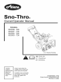
Sno-Throo
Owner/Operator
Manual
Models
932036-524
932037-724
932504-524
932505-724
U.S. Patents Pending
_
_
_ENGLISH
FRANQAIS
ESPAKIOL
Transfer
model &
serial number
label from
Coller I'autocollant du
module et du numero de
serie dans cet encadr&
product
registration
here.
Transferir aquila etiqueta
del modelo y nOmero de
serie del registro del
producto.
03249300C 3/04
Supersedes 03249300,A,B
Printed in USA
Ariens Company
655 West Ryan Street
RO. Box 157
Brillion, Wisconsin
54110-0157
USA
Telephone:
(920) 756-2141
Facsimile:
(920) 756-2407
MODEL CERTIFICATE OF CONFORMITY ISSUED BY THE
M.ANUFA.CTURER - CERTIFICAT DE CONFORMITE_ DU MODELE
DELIVRE PAR LE FABRICANT - MODELL-KONFORMIT,_,TSBE SCHEINIGUNG AUSGESTELLT DURCH DEN HERSTELLER CERTIFICATO DI COMFORMIT,_ DEL MODELLO RILASCIATO DAL
PRODUTTORE - CERTIFICADO DE CONFORMIDAD DEL MODELO
PROVISTO POR EL FABRICANTE - MODELLSERTIFIKAT
FOR
OVERENSSTEMMELSE
UTSTEDT AV FABRIKANT TILLVERKARENS MODELLCERTIFIKAT OM
OVERENSST,_MMELSE
- VALMISTAJAN ANTAMA VAKUUTUS
MALLIN M.,_,_R,_,YSTEN MUKAISUUDESTA - SWlADECTWO
ZGODNOSCI MODELU WYDANE PRZEZ PRODUCENTA
We the undersigned, ARIENS COMPANY, certify that: - Nous, soussignes ARIENS
COMPANY, certifions que :- Der Unterzeichnete, ARIENS COMPANY, bescheinigt, dass: La sottoscritta societ&, ARIENS COMPANY, certifica che: - Nosotros, los abajo firmantes,
ARIENS COMPANY, certificamos que: - Undertegnede, ARIENS COMPANY, bekrefter at: Undertecknad, ARIENS COMPANY, intygar att: - Allekirjoittanut, ARIENS COMPANY,
vakuuttaa, ett&: - My, nizej podpisani, ARIENS COMPANY, o_wiadczamy, ze:
Type: - Tipo: Tyyppi: - Typ: -
WALK BEHIND SNOW THROWER - LES CHASSE_S-NEIGE
AUTOTRACTES - HANDGEFUHRTE SCHNEEFRASE - SPAZZANEVE
SEMOVENTE - CAMINAR POR DETRAS DE LA LANZADORA DE NIEVE
- SNOFRESER - GA BAKOM SNOSLUNGAN - K,_SINOHJAILTAVA
LUMILINKO - ODGARNIACZ SNIEGU DO PROWADZENIA PRZED SOB,_
Trade Name: - Appellation commerciale : Handelsbezeichnung:
- Nome commerciale:Nombre
comercial:Handelsnavn:Handels-beteckning:Kauppanimi: - Nazwa handlowa:
ARIENS Sno-Thro
Model: - Modele : - Modell: - Modello: - Modelo: - Modell: Modell: - Malli: - Model:
Serial # Range: - Gamme de numeros de Serie : Seriennummern: - Gamma n. di serie: - Rango de n° de serie: Serienummeromr&de:
- Serienummer-omr&de: Sarjanumerot: - Zakres, numer seryjny:
Conforms to: - Conforme & : - Entspricht: - Conforme a: Conforme a: - E ri samsvar med:- Uppfyller: T&ytt&& seuraavat vaatimukset: - Jest zgodny z:
Representative Measured Sound Power Level
(Lwa) - Niveau de puissance acoustique
representatif - Repr&sentativer gemessener
Ger&uschpegel - Livello di potenza sonora
rappresentativo rilevato - Nivel de potencia
act_stica representativo medido Representativt m< lydeffektniv& Representativ uppm&tt Ijudniv& - Edustava,
mitattu &&nen tehotaso - Zmierzony
reprezentatywny poziom mocy akustycznej
932504
932505
> 001000
> 000101
98/37/EC, 89/336/EEC,
92/31/EEC, 2000/14/EC
(V)
Guaranteed Sound Power Level (Lwa) Niveau garanti de puissance acoustique Garantierter Ger&uschpegel - Livello di
potenza sonora garantito - Nivel de potencia
act_stica garantizado - Garantert
lydeffektniv& - Garanterad Ijudniv& Taattu &&nen tehotaso - Gwarantowany
reprezentatywny poziom mocy akustycznej
932504:101
dB A
932504:104
dB A
932505:100
dB A
932505:104
dB A
2
Philip
J,Smucker:
Manager
ofProduct
Conformance
(Keeper
ofTechnical
File)
- Responsable
dela
- Firmaconformite
desproduits
(enpossession Signature
UnterschriftSignatu rdudocument
technique)
- Leiter
der
Namnteckning Produkt(Jbereinstimmung
(Verantwortlicher
Allekirjoitus - Podpis
fordietechnische
Dokumentation)
- Addetto
aliaconformit&
delprodotto
(inpossesso
deldocumento
tecnico)
- Gerente
de
conformidad
delosproductos
(enposesi6n
deldocumento
tecnico)
- Ansvarlig
for
3roduktsamsvar
(innehaver
avteknisk
ill)Chef
f6rprodukt6verensst&mmelse
(innehavare
avtekniska
dokument)
Tuotteen
vaatimustenmukaisuudesta
vastaava
johtaja
(teknisen
tiedoston
haltija)
Zarzadzajacy
Zgodno_cia
Produktu
(przechowujatcy
Dokumentacj_
Techniczna)
._
5/21/2003
Date
- Data
Datum
Fecha
- Dato
P&iv&ys
- Data
t _
CE Sound and Vibration - Niveau sonore et vibration CE - CE-Ger&uschpegel
und Vibrationswerte - Livello sonoro e vibrazioni CE - Sonido y vibraci6n CE CE-lydniv& og Vibrasjonsm&ling - CE Ijudniv& och Vibrations-m&tning CE-melutaso T&rin& - CE D:_wi_ku i Wibracji
Model: - Modele : - Modell: - Modello: - Modelo: - Modell: - Modell: Malli: - Model:
932504
932505
Oper. Ear Sound Pressure (Lpa) in dB A- Pression acoustique Pression
sonore aux oreilles de I'op@ateur (Lpa) en dB A - Ger&uschst&rke am Ohr
des Bedieners (Lpa) in dBA - Potenza sonora percepita dall'operatore
(Lpa) in dB A - Presi6n de sonido en el oido (Lpa) in dB A - Lydtrykk i
fererens {)re (Lpa) in dBA - Vid f6rarens position (Lpa) i dB A - Kuljettajan
korvaan kohdistuva &&nipaine (Lpa)/dB A- Robocze ci_nienie akustyczne
na uchu (Lpa) w decybelach A
88
88
Vibration Measure (m/sec 2) @ Operator Hands - Niveau de vibration aux
mains de I'op@ateur - Vibrationswerte An den H&nden des Bedieners Misura delle vibrazioni alle mani dell'operatore - Cantidad de vibraci6n en
las manos del operador - Vibrasjonsm&ling ved brukerens hender Vibrationsm&tning vid f6rarens h&nder - T&rin& kuljettajan k&siss& Pomiar wibracji na rCkach operatora
X
8.3
4.1
Y
3
1.6
Z
4.9
2.6
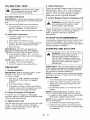
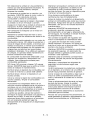
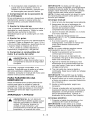
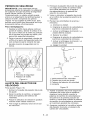
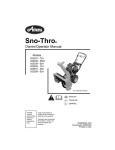
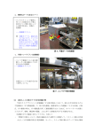
ENGLISH
ESPANOL
FRAN(_AIS
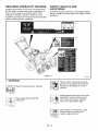
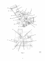
1.Traction
Drive
Clutch
Bail 1.Levier
d'embrayage
de
1.Palanca
delembrague
I'entrafnement
dela
delatransmisiSn
dela
2.Speed
Selector
traction
tracciSn
3.Chute
Crank
devitesses 2.Selector
develocidad
4.Muffler
Guard
(932504, 2.Selecteur
delatolva
505)
3.Manivelle
delagoulotte 3.Manivela
4.Garant
dusilencieux 4. Protector
delsilenciador
5.Discharge
Chute
Deflector
(932504,
505)
(932504,
505)
delatolva
de
6.Discharge
Chute
5.Deflecteur
delagoulotte 5.Deflector
d'evacuation
7.Impeller
descarga
6.Goulotte
d'evacuation 6.Tolva
8.Auger
dedescarga
7.Turbine
9.Auger
Gearcase
7.Propulsor
8.Rotor
8.Sinfin
10.Scraper
Blade
9.Boftier
derenvoi
durotor 9.Cajadeengranajes
11.OilFillandDipstick
del
10.Lame
racleuse
sinfin
12.GasTank
andCap
13.Recoil
Starter
Handle 11.Tube
deremplissage
en 10.Cuchilla
raspadora
14.Electric
Starter
(932036, huile
etjauge
11.Llenado
deaceite
y
12.Reservoir
decarburant
varilla
medidora
037)
15.Primer
Bulb
etbouchon
12.DepSsito
degasolina
dudemarreur
16.Throttle
(Engine
Stop) 13.Poignee
ytapa
cordon
17.Ignition
Switch
13.Manilla
dearranque
de
14.Demarreur
electrique
retroceso
(push-pull)
18.Choke
14.Arranque
electrico
(932036,
037)
19.Spark
Plug
andWire
15.Poire
d'amor£age
(932036,
037)
15.Perilla
decebado
20.Runner(s)
16.Commande
desgaz
21.BeltCover
(arr6t
dumoteur)
16.Acelerador
(parada
de
22.J-Bolt
17.Cledecontact
motor)
23.Handlebar
17.Interruptor
deencendido
(pousser-tirer)
24.Attachment
Clutch
Bail 18.Starter
(tiro-empujel)
25.FuelShut-off
Valve
18.Estrangulador
19.Bougie
etfil
26.AxleLock
Pin
19.Bujiaycable
20.Patin(s)
21.Couvercle
ducourroie 20.Guia(s)
22.VisenJ
21.Cubierta
delacorrea
23.Guidon
22.Perno
enJ
24.Levier
d'embrayage 23.Manillar
deI'outil
24.Palanca
delembrague
25.Robinet
decarburant
delaccesorio
25.Valvula
decorte
del
26.Broche
deblocage
de
I'essieu
combustible
26.Pasador
detraba
deleje
6
7
10
20
9
19
11
12
17
18
13
14
16
15
0S2420
Figure 1
0S0503
Controls and Features
................
Safety ..............................
4
Storage ............................
27
7
Troubleshooting
28
.....................
Assembly ..........................
12
Service Parts .......................
27
Operation ..........................
14
Accessories
27
Maintenance ........................
18
Specifications
20
Warranty ...........................
Service and Adjustments
.............
........................
......................
29
30
I_bitTo_o]_l
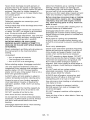
THE MANUAL
Before operation of unit, carefully and
completely read your manuals. If used
improperly, this unit could be dangerous and
cause personal injury or property damage.
The contents will provide you with safety
instructions for the safe use of your unit during
normal operation and maintenance.
All reference to left, right, front, or rear are
given from operator standing in operation
position and facing the direction of forward
travel.
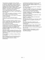
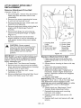
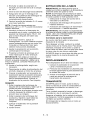
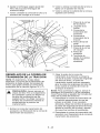
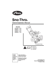
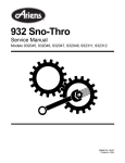
MODEL AND SERIAL NUMBERS
When ordering replacement parts or making
service inquiries, know the Model and Serial
numbers of your unit and engine.
Numbers are located on the product
registration form in the unit literature package.
They are printed on a serial number label,
located on the frame of your unit.
Serial Number
• Record Engine Model and Serial number
here.
PRODUCT REGISTRATION
The Ariens dealer must register the product at
the time of purchase. Registering the product
will help the company process warranty claims
or contact you with the latest service
information. All claims meeting requirements
during the limited warranty period will be
honored, whether or not the product
registration card is returned. Keep a proof of
purchase if you do not register your unit.
Customer Note: If the dealer does not
register your product, please fill out, sign, and
return the product registration card to Ariens
or go to www.ariens.com.
UNAUTHORIZED
PARTS
REPLACEMENT
Use only Ariens replacement parts. The
replacement of any part on this vehicle with
anything other than an Ariens authorized
replacement part may adversely affect the
performance, durability, or safety of this unit
and may void the warranty. Ariens disclaims
liability for any claims or damages, whether
warranty, property damage, personal injury or
death arising out of the use of unauthorized
replacement parts.
Label
Figure 2
OS0522
• Record Unit Model and Serial numbers
here.
For a brief list of replacement parts see
Service Parts in this manual. To obtain a
complete parts manual, find your model and
serial number. Then go to www.ariens.com or
call 1-800-678-5443.
GB - 6
© Copyright 2003 Ariens Company
DISCLAIMER
Ariens reserves the right to discontinue, make
changes to, and add improvements upon its
products at any time without public notice or
obligation. The descriptions and specifications
contained in this manual were in effect at
printing. Equipment described within this
manual may be optional. Some illustrations
may not be applicable to your unit.
NOTE: To locate your nearest Ariens Dealer,
call 1-800-678-5443 or go to www.ariens.com
on the internet.
A
2. Understand all Safety Precautions
provided in the manuals.
3. Review control functions and operation of
the unit. Do not operate the Sno-Thro
unless all controls function as described
in this manual.
DELIVERY
Customer Note: If you have purchased this
product without complete assembly and
instruction by your retailer, it is your
responsibility to:
1. Read and understand all assembly
instructions in this manual. If you do not
understand or have difficulty following the
instructions, contact your nearest Ariens
Dealer for assistance. Make sure all
assembly has been properly completed.
WARNING: Improper assembly or
adjustments can cause serious injury.
4. Review recommended lubrication,
maintenance and adjustments.
5. Review Limited Warranty Policy.
6. Fill out a Product Registration Card and
return the card to the Ariens Company or
go to www.ariens.com.
[,.'f-'1=1=l_
A
WARNING: To avoid injury to hands
and feet, always disengage clutches,
shut off engine, and wait for all
movement to stop before unclogging
or working on snow thrower.
A
ARNING: POTENTIALLY
HAZARDOUS
SITUATION! If not
avoided, COULD RESULT in death or
serious injury.
_
CAUTION:
HAZARDOUSPOTENTIALLY
SITUATION! If not
avoided, MAY RESULT in minor or
moderate injury. It may also be used to
alert against unsafe practices.
Keep hands and feet away from auger
and impeller.
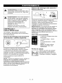
SAFETY ALERTS
Look for these symbols to point
out important safety precautions.
They mean:
Attention!
Become Alert!
NOTE: General reference information for
proper operation and maintenance practices.
IMPORTANT: Specific procedures or
information required to prevent damage to unit
or attachment.
Obey
PRACTICES AND LAWS
Personal Safety Is
Involved!
The Message!
The safety alert symbols above and signal
words below are used on decals and in this
manual. Read and understand all safety
messages.
A
NOTATIONS
ANGER: IMMINENTLY
HAZARDOUS
SITUATION! If not
avoided, WILL RESULT in death or
serious injury.
Practice usual and customary safe working
precautions, for the benefit of yourself and
others. Understand and follow all safety
messages. Be alert to unsafe conditions and
the possibility of minor, moderate, or serious
injury or death. Learn applicable rules and
laws in your area. Always follow the practices
set forth in this manual.
GB -7
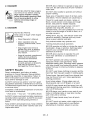
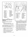
REQUIRED OPERATOR TRAINING
Original purchaser of this unit was instructed
by the seller on safe and proper operation. If
unit is to be used by someone other than
original purchaser; loaned, rented or sold,
ALWAYS provide this manual and any needed
safety training before operation.
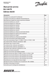
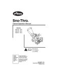
SAFETY DECALS AND
LOCATIONS
ALWAYS replace missing or damaged Safety
Decals. Refer to figure below for Safety Decal
locations.
Figure 3
©$2440
1. WARNING!
persons or property that may be
injured
or damaged
by thrown
Never direct
discharge
towards
objects.
Read Owner/O 3erator Manual.
OL0910
OL180I
Wear appropriate
protection.
operating. Keep children out of
work area and under watchful
Keep people away from unit while
care of a responsible adult.
hearing
OL4370
OL4690
Stop engine, remove key, read
manual before making any
repairs, adjustments.
OL4010
GB -8
2. DANGER!
©$2070
NEVER allow children to operate or play on or
near unit. Be alert and shut off unit if children
enter area.
ROTATING PARTS! Stop engine
and remove key before clearing.
High speed impeller rotates
below discharge opening. Wait
for all moving parts to stop
before removing clogs or
servicing.
Keep area of operation clear of all toys, pets,
and debris. Thrown objects can cause injury.
Check for weak spots on docks, ramps or
floors. Avoid uneven work areas and rough
terrain. Stay alert for hidden hazards.
Avoid uneven and rough terrain. DO NOT
operate near drop-offs, ditches, or
embankments. Unit can suddenly turn over if a
wheel is over the edge of a cliff or ditch, or if
an edge caves in.
&DANGER!
Keep clear of auger while engine
is running.
_
DO NOT allow adults to operate unit without
proper training.
• Read Operator's
ROTATING
PARTS. Manual.
• Allow operation only by
properly trained adult, never
children.
Stop engine and remove
ignition key prior to leaving
the operator's position for
any reason.
Keep all controls, guards and
safety devices properly
serviced and functional.
Never direct discharge
towards persons or property
that may be injured or
damaged by thrown objects.
SAFETY RULES
Read, understand, and follow all safety
practices in Owner/Operator Manual before
beginning assembly or operating. Failure to
follow instructions could result in personal
injury and!or damage to unit.
ALWAYS remove key and!or wire from spark
plug before assembly, maintenance or service.
Unintentional engine start up can cause death
or serious injury.
Complete a walk around inspection of unit and
work area to understand:
• Work area • Your unit • All safety decals
ALWAYS check overhead and side clearances
carefully before operation. ALWAYS be aware
of traffic when operating along streets or
curbs.
Keep children and people away. Keep children
out of work area and under watchful care of a
responsible adult.
Falling snow, fog, etc. can reduce vision and
cause an accident. Operate unit only when
there is good visibility and light.
Only trained adults may operate unit.
Training includes actual operation.
NEVER operate unit after or during the use of
medication, drugs or alcohol. Safe operation
requires your complete and unimpaired
attention at all times.
NEVER allow anyone to operate this unit
when their alertness or coordination is
impaired.
DO NOT operate unit without wearing
adequate winter outer garments. Wear
adequate safety gear, including safety glasses
with side shields, and protective gloves. Wear
proper footwear to improve footing on slippery
surfaces.
DO NOT wear loose clothing or jewelry and tie
back hair that may get caught in rotating parts.
Protect eyes, face and head from objects that
may be thrown from unit. Wear appropriate
hearing protection.
Avoid sharp edges. Sharp edges can cut.
Moving parts can cut off fingers or a hand.
ALWAYS keep hands and feet away from all
rotating parts during operation. Rotating parts
can cut off body parts.
NEVER place your hands or any part of your
body or clothing inside or near any moving
part while unit is running.
ALWAYS keep hands away from all pinch
points.
DO NOT touch unit parts which might be hot
from operation. Allow parts to cool before
attempting to maintain, adjust or service.
GB - 9
Never
direct
discharge
towards
persons
or
Abnormal Vibrations are a warning of trouble.
property
thatmaybeinjured
ordamaged
by Striking a foreign object can damage unit.
thrown
objects.
Use
extreme
caution
ongravel Immediately stop unit and engine. Remove
surfaces.
Stay
alertforhidden
hazards
or
key and wait for all moving parts to stop.
traffic.
Adjust
Runners
soScraper
Blade
does Remove wire from spark plug. Inspect unit and
notcontact
gravel.
make any necessary repairs before restart.
DONOT
throw
snow
anyhigher
than
Before cleaning, removing clogs or making
necessary.
any inspections,
repairs, etc.: disengage
clutch(es), stop unit and engine, remove
Deflected
materials
cancause
injury
and
key, allow moving parts to stop. Allow hot
property
damage.
to cool.
Always
stand
clear
ofthedischarge
area
when parts
Run
unit
a few minutes after clearing snow to
operating
thisunit.
prevent freeze-up of attachment.
Fumes
fromengine
exhaust
cancause
injury
attachment when not in use.
ordeath.
DONOTrunengine
inanenclosed Disengage
Disengage all clutches before starting engine.
area.
Always
provide
good
ventilation.
runners to clear gravel or crushed rock
ALWAYS
disengage
attachment,
stopunitand Adjust
surfaces safely.
engine,
remove
keyandallow
moving
parts
to Never leave a running unit unattended.
stopbefore
leaving
operator's
position.
ALWAYS shut off engine before leaving unit.
ROTATING IMPELLER CAN CAUSE
SERIOUS INJURY. NEVER ATTEMPT TO
UNCLOG OR CLEAN UNIT WHILE ENGINE
IS RUNNING.
Read, understand, and follow all instructions
the manual and on the machine before
starting.
ALWAYS remove key to prevent unauthorized
use.
Never carry passengers.
in
Understand:
• How to operate all controls.
• The functions of all controls.
• How to STOP in an emergency.
Before starting engine, disengage control(s).
Use only approved extension cords and
receptacles when starting units equipped with
electric starter. DO NOT connect electric
starter cord to any wiring system that is not a
three-wire grounded system.
ALWAYS allow unit and engine to adjust to
outdoor temperatures before clearing snow.
Always be sure of your footing, especially
when operating in reverse or leaving the
operator's position. Walk, never run during
operation.
DO NOT overload the machine capacity by
attempting to clear snow at too fast a rate.
DO NOT operate at too fast a rate.
Slow down and turn corners slowly.
Do not operate in reverse unless absolutely
necessary. ALWAYS back up slowly. Always
look down and behind before and while
backing.
Check clutch and brake operation frequently.
Adjust and service as required. All motion of
drive wheels and auger/impeller must stop
quickly when control levers are released.
DO NOT operate on steep slopes. DO NOT
clear snow across the face of slopes. Keep all
movement on slopes slow and gradual. DO
NOT make sudden changes in speed or
direction. Use a slow speed to avoid stops or
shifts on slopes. Avoid starting or stopping on
a slope.
DO NOT park unit on a slope unless
absolutely necessary. When parking on a
slope always block the wheels.
ALWAYS shut off engine, remove key, and
close fuel shut-off valve or drain fuel when
transporting
unit on a truck or trailer.
Use extra care when loading or unloading unit
onto trailer or truck.
Secure unit chassis to transport vehicle.
NEVER secure from rods or linkages that
could be damaged.
DO NOT transport machine while engine is
running.
Keep unit free of ice or other debris. Clean up
oil or fuel spills.
Disengage attachment drive when traveling
from one work area to another.
GB- 10
Thisproduct
isequipped
withaninternal
ALWAYS
keep
protective
structures,
guards,
combustion
typeengine.
DONOT
useuniton andpanels
ingood
repair,
inplace
and
ornear
anyunimproved,
forest-covered
or
securely
fastened.
NEVER
modify
orremove
brush
covered
landunless
exhaust
system
is safety
devices.
equipped
withaspark
arrester
meeting
DONOT
change
engine
governor
settings
or
applicable
local,
state
orfederal
laws.
Aspark over-speed
engine.
arrester,
ifitisused,
must
bemaintained
in
Fumes
from
engine
exhaust
cancause
injury
effective
working
order
byoperator.
ordeath.
DONOTrunengine
inanenclosed
Fuel
ishighly
flammable
anditsvapors
are
Always
provide
good
ventilation.
explosive.
Handle
withcare.
Useanapprovedarea.
ALWAYS
maintain
unit
i
nsafe
operating
fuelcontainer.
condition.
Damaged
orworn
o
utmuffler
can
NOsmoking,
NOsparks,
NOflames.
ALWAYScause
fireorexplosion.
allow
engine
tocoolbefore
servicing.
Keep
allhardware
properly
tightened.
Check
NEVER
fillfueltankwhen
engine
isrunning
or shear
bolts
frequently.
hotfromoperation.
Maintain
orreplace
safety
andinstruction
NEVER
fillordrain
fueltankindoors.
labels,
asnecessary.
Replace
fuelcapsecurely
andclean
upspilled NEVER
store
unitwithfuelinfueltank,
inside
fuel.
abuilding
where
anyignition
sources
are
Never
fillcontainers
inside
avehicle
orona
present.
truck
ortrailer
bedwithaplastic
liner.
Always Shutofffuelandallow
engine
tocool
place
containers
ontheground
away
from
completely
before
storing
inclosed
areaor
yourvehicle
before
filling.
covering
unit.
When
practical,
remove
gas-powered
Forextended
storage,
clean
unitthoroughly.
equipment
fromthetruck
ortrailer
andrefuel
it See
Engine
Manual
forproper
storage.
ontheground.
Ifthisisnotpossible,
then
Use
onlyattachments
oraccessories
designed
refuel
such
equipment
onatrailer
witha
portable
container,
rather
thanfrom
agasolineforyourunit.
dispenser
nozzle.
Check
components
frequently.
Ifworn
or
replace
withmanufacturer's
Keep
thenozzle
incontact
withtherimofthe damaged,
parts.
fueltankorcontainer
opening
atalltimes
until recommended
fueling
iscomplete.
Donotuseanozzle
lockopen
device.
Iffuelisspilled
onclothing,
change
clothing
immediately.
Before
tipping
unitupontohousing,
remove
fuelsonospills
willoccur.
Ensure
unitis
secure
andwillnottipoverduring
maintenance.
GB-11
,_
,_
Tools
WARNING: AVOID INJURY. Read
and understand the entire Safety
section before proceeding.
WARNING: Dropping or tipping over
boxed unit could result in personal
injury or damage to unit.
Required:
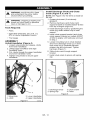
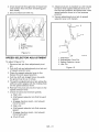
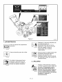
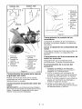
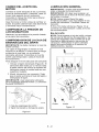
Install
Crank
Discharge
Chute and Chute
(Figure 5, 6, and 7)
NOTE: See Figure 5 for the items to install on
the unit.
1. Grease chute seat
greased).
2. Remove hardware
support bracket on
from top of engine
(if not already
(and chute crank
models 932037 & 505)
(Figure 6).
3. Install discharge chute by positioning the
chute ring under retainer clip on seat
support.
• Pliers
• Open-End Wrenches: 3/8, 7/16, 1/2,
9/16 in. and/or Adjustable Wrench
• Tire Gauge
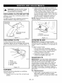
ASSEMBLY
Unfold Handlebar
(Figure 4)
1. Loosen wing knobs and release J-bolts
from lower handlebar.
2. Unfold upper handlebar and align
handlebar holes.
3. Put J-bolts through the upper handlebar
and lower handlebar holes.
4. Tighten wing knobs to secure upper
handlebar.
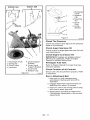
4. Install chute support bracket (and chute
crank support bracket on models 932037
& 505) to engine with hardware removed
in step 2.
5. Loosen mounting nut on chute bracket
and move discharge chute up or down
until chute ring is centered between
retainer clip and chute seat. Tighten
hardware (Figure 7).
6. Slide chute crank through support
bracket.
7. Install chute crank to pinion with spring
clip.
2
3
4
1. Discharge Chute
2. Spring Clip
4
3. Chute Crank
4. Pinion
Figure 5
1. Wing Knob
2. J-Bolt
3. Lower Handlebar
4. Upper Handlebar
Figure 4
os3000
GB- 12
os3500
932037,505
932036, 504
I
I
4
61
1. Discharge
Chute
3
2. Retainer
Clip
3. Mounting
Nut
4. Chute
Ring
5. Chute
Bracket
5
Figure 7
Check
OS4500
Tire Pressure
Check tire pressure and adjust to the pressure
listed on tire sidewall.
Check
Auger
Gearoase
Oil
Check oil level in auger gearcase
and Adjustments).
2
Check
1
Discharge Chute
Spring Clip
Chute Crank
Hardware
5. Chute Support
Bracket
6. Chute Crank
Support Bracket
7. Chute Seat
8. Retainer Clip
Figure 6
Crankcase
Oil
IMPORTANT: Engines are shipped without
5W-30 oil in crankcase. Refer to Engine
Manual for detailed instructions.
7
1.
2.
3.
4.
Engine
(see Service
OS4000
Fill Engine
Fuel Tank
Refer to Engine Manual for proper fuel type
and tank capacity.
Check
Function
of all Controls
Ensure unit runs and performs properly. Refer
to Operation.
Run in Attachment
Belt
1. Start unit in a well-ventilated area
according to Starting and Shut-Off in
Operation.
2. Engage attachment clutch bail and run
attachment for about 15 minutes.
3. Stop unit, wait for all moving parts to stop,
and remove spark plug wire.
4. Adjust clutch according to Attachment
Clutch/Brake Adjustment in Service and
Adjustments.
GB- 13
Ignition
,_
Switch
WARNING: AVOID INJURY. Read
and understand the entire Safety
section before proceeding.
1. "Stop"- pulled out
2. "Run"- pushed in
WARNING: To avoid injury to hands
and feet, always disengage clutches,
shut off engine, and wait for all
movement to stop before unclogging
or working on snow thrower.
Keep hands and feet away from auger
and impeller.
NOTE: DO NOT twist key
after it is inserted.
i
Key Switch has two positions:
1
Primer
Bulb
--
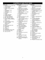
CONTROLS AND FEATURES
Pushing the primer bulb in adds
See Figure 1 for all Controls and Features
locations.
Traction
Drive
Clutch
- Left Hand
Refer to Starting and Shut Off.
fuel for easier engine start.
Bail
Speed
2
/ ....
!
0L2702
Squeeze the Traction Drive Clutch Bail against
the Handlebar (1) to engage wheel drive for
propelling unit. Forward speed will vary
according to snow depth and moisture
content.
Release bail (2) to stop movement.
NOTE: When traveling to or from the area to
be cleared, press down on the handlebars
enough to raise the front of the unit slightly off
the surface. Engage the traction drive clutch
without engaging the attachment drive clutch.
Attachment
Clutch
- Right
Selector
The Speed Selector controls the unit travel in a
forward or reverse direction when positioned
in notch of speed.
Hand
W
W
6
5
4321
_
1
2
mm
©$2400
Forward:
Bail
(6) Fastest
(1) Slow
m
Reverse:
b/-q
1 C
_
!_
1) Slow
(2) Fast
OLI692
Squeeze Attachment Clutch Bail against
handlebar (1) to engage attachment. Release
both clutch bails (2) to disengage power and
apply brake to attachment.
IMPORTANT: DO NOT change motion from
forward to reverse with clutch engaged.
Forward speed can be changed without
declutching.
IMPORTANT: If the belt squeals when the
attachment clutch bail is engaged, the
attachment drive may be frozen. Immediately
release the attachment clutch bail and move
the unit into a heated area to thaw.
GB - 14
Choke Control Knob
IMPORTANT: DO NOT force frozen chute
controls. Start engine and run for 3-5 minutes
to thaw. If still frozen, take to warm place until
controls are free.
1. Choke Closed position:
chokes off air to engine for
easier start.
I\l
Axle Lock Pin (Figure 8)
Wheel Unlocked
2. Choke Open position:
allows for normal
operation.
IMPORTANT: Gradually
open choke after engine
starts.
00
Throttle
The throttle controls the engine
speed. To increase or decrease
the engine speed, adjust to:
1. Fast (normal or warm starts)
2. Part-Throttle
3. Slow (cold weather starts)
_a
@4
4. Stop (engine is off)
Wheel
Locked
0L2720
Electric
Starter
The electric starter will start a properly choked
and cranked engine when the starter button is
pushed. Refer to Starting and Shut-Off,
Recoil
Starter
Handle
When pulled, handle will turn engine over.
IMPORTANT: DO NOT let handle snap back
against starter.
Discharge
Chute
Deflector
ALWAYS position discharge chute deflector at
a safe angle before starting engine.
DO NOT throw snow any higher than
necessary.
Push deflector handle forward or down to
throw snow lower. Pull deflector handle up or
to the rear to throw snow higher.
Figure 8
IMPORTANT: If Chute Deflector does not stay
in set position, adjust as directed in Service
and Adjustments, or repair before operation.
Use the axle lock pin to lock or unlock the right
wheel. Lock the right wheel to increase
traction; unlock the right wheel to allow for
easier turning of the unit.
Discharge
Scraper
Chute
Discharge chute rotates 220 ° .
ALWAYS position discharge chute in safe
direction and angle, away from operator and
bystanders, before starting engine.
Chute
Crank
IMPORTANT:
If chute does not stay in set
position, adjust as directed in Service and
Adjustments, or repair before operation.
Rotate the Chute with Discharge Chute Crank
Handle.
Blade
The scraper blade allows the back of the
housing to keep better contact with the surface
being cleared. It also prevents damage to the
housing from normal wear.
IMPORTANT: DO NOT allow Scraper Blade to
wear too far or Auger/Impeller housing will
become damaged.
Runners
The runners control the distance between the
scraper blade and the ground. Adjust runners
equally to keep blade level with the ground.
Refer to Pre-Startfor recommended settings.
GB- 15
FILLING FUEL TANK
,_
WARNING: AVOID INJURY. Read
and understand the entire Safety
section before proceeding.
Fuel Shut-Off
Valve
IMPORTANT: The fuel shut-off valve MUST be
in the closed position prior to transporting the
unit.
The fuel shut-off valve has two positions:
• Closed Position: Use this position to
service, transport, or store the unit.
• Open Position: Use this position to run the
unit.
To add
fuel to fuel tank:
4. Adjust
Runners
Check and adjust Runners (see Service and
Adjustments). Allow 1/8 in. (3 mm) between
scraper blade and hard, smooth surface(s).
Allow 1-1/4 in. (30 mm) between scraper
blade and uneven or gravel surfaces.
5. Check
_,
Engine
Fuel & Crankcase
Oil
ARNING: AVOID INJURY. Read
and understand the entire Safety
section before proceeding.
Check and add fuel if required. Check that the
engine crankcase oil is full using dipstick.
Refer to Engine Manual for detailed
instructions.
1. ALWAYS place unit in open or wellventilated area.
TO STOP IN AN EMERGENCY
2. Stop engine and allow to cool.
Immediately release both control bails to stop
unit in an emergency. Stop engine, remove
key and wait for all rotating parts to stop before
leaving operator's position.
3. Clean Fuel Cap and surrounding area to
prevent dirt from entering Fuel Tank.
4. Remove Cap.
IMPORTANT: DO NOT use gasohol or
gasoline containing alcohol. See Engine
Manual for correct type and grade of fuel.
5. Fill fuel tank to within 1/2 in. (1.2 cm)
below bottom of filler neck with unleaded
gasoline.
STARTING AND SHUT OFF
_L,
NOTE: Tank capacity is 2 qt (1.96 L).
6. Replace Fuel Cap and tighten.
7. ALWAYS clean up any spilled fuel.
PRE-START
1. Frozen
Impeller
IMPORTANT: Before starting engine, check
impeller to be sure it is not frozen.
To check impeller:
1. With key in "Stop" position, squeeze
Attachment Clutch Bail to Engaged
position.
2. Pull Recoil Starter Handle.
3. If Impeller is frozen, (cannot pull Starter
Handle) move unit to a heated area and
thaw to prevent possible damage.
2. Check
Function
of Clutches
If clutches do not engage or disengage
properly, adjust or repair before operation (see
Service and Adjustments).
3. Adjust
Axle
Lock
Use the axle lock pin to lock or unlock the right
wheel. Lock the right wheel to increase
traction; unlock the right wheel to allow for
easier turning of the unit.
ARNING: FAILURE
FOLLOW
INSTRUCTIONS
could TO
result
in
personal injury and/or damage to
unit. DO NOT attempt to start your
unit at this time. Read entire Owner/
Operator Manual and the Engine
Manual first.
IMPORTANT: Allow unit and engine to adjust
to the outdoor temperatures before clearing
snow. Before shut-off, run the attachment a
few minutes to prevent freeze-up.
NOTE: Try out each control without the engine
running to see how it works and what it does.
Manual
Start
1. Turn discharge chute straight ahead.
2. Make sure that the traction clutch and
attachment drive clutch bails are fully
disengaged.
3. Push Primer Bulb 2 or 3 times for cold
engine.
NOTE: When temperature is below -15 ° F
(-26 ° C) additional priming may be needed.
4. If engine is cold, apply choke. See Engine
Manual for detailed instructions.
NOTE: A warm engine requires less choking
than a cold engine.
5. Set throttle to proper starting position.
6. Insert key into ignition switch and push
into RUN position. DO NOT twist key after
it is inserted.
GB- 16
7.Grasp
starter
handle
andpullrope
out
2. Run Impeller a few minutes after use to
slowly
until
itpulls
harder.
Letrope
rewind
prevent freeze-up of Impeller.
slowly.
3. Release Attachment Clutch Bail and wait
8.Pullrope
witharapid
continuous
fullarm
for all moving parts to come to a complete
stroke.
Letroperewind
slowly.
stop.
IMPORTANT:
DONOT
letStarter
Handle
4. Move Throttle to the "Stop" position.
snap
against
Starter.
5. Remove key.
9.Repeat
steps
7and8until
engine
starts.
(Ifengine
does
notstart,
referto
SNOW REMOVAL
Troubleshooting.)
10. Adjust choke as needed.
11. Set throttle to Part Throttle or Slow
position for adaptation to outside
temperature or travel. Set throttle to Fast
position for normal operation.
Electric
Start
1. Connect extension cord to prongs on
starter.
IMPORTANT: Prevent damage to unit. Know
voltage of your starter and only use matching
outlets.
2. Plug extension into 120V 3-wire,
grounded outlet.
3. Turn discharge chute straight ahead.
4. Make sure that the traction clutch and
attachment drive clutch bails are fully
disengaged.
5. Push Primer Bulb 2 or 3 times for cold
engine.
NOTE: When temperature is below -15 ° F
(-26 ° C) additional priming may be needed.
6. Insert key into ignition switch on engine
and push into "Run" position. DO NOT
twist key after it is inserted.
7. If engine is cold, apply choke. A warm
engine requires less choking than a cold
engine. See Engine Manual for detailed
instructions.
8. Set throttle to proper starting position.
9. Press starter button on engine until
engine starts.
IMPORTANT: DO NOT operate starter more
than 15 seconds per minute, as overheating
and damage can occur. (If engine does not
start, refer to Troubleshooting.)
10. Adjust choke as needed.
11. Disconnect
starter.
power cord from outlet, then
12. Set throttle to Part Throttle or Slow
position for adaptation to outside
temperature or travel. Set throttle to Fast
position for normal operation.
Shut
Off
1. Release Traction Drive Clutch Bail and
allow unit to come to a complete stop.
IMPORTANT: Allow unit and engine to adjust
to the outdoor temperatures before clearing
snow.
NOTE: Attachment clutch should be engaged
before wheel drive clutch when throwing snow.
1. Select Speed Control position and
direction.
2. Engage Attachment
Bail.
Clutch - Right Hand
3. Engage Traction Drive Clutch - Left Hand
Bail.
IMPORTANT: DO NOT overload unit capacity
by attempting to clear snow at too fast a rate.
Use slow speed to clear deep or hard packed
snow.
Tips for Operation
Snow is best removed as soon as possible
after snow fall.
To clear an area, run unit in an overlapping
series of paths. For large areas, start in the
middle and throw snow to each side, so snow
is not cleared more than once.
ALWAYS direct snow away from area to be
cleared and with direction of the wind.
TRAVELING
To travel from one work area to another:
1. Set Throttle to Slow or Part-Throttle
position.
2. Press down on handlebars enough to
raise front of unit slightly off surface.
3. Engage wheel drive clutch without
engaging attachment drive clutch.
TRANSPORT
ALWAYS shut off engine, remove key, and
close fuel shut-off valve when transporting unit
on a truck or trailer.
Use extra care when loading or unloading unit
onto trailer or truck.
Secure unit chassis to transport vehicle.
NEVER secure from rods or linkages that
could be damaged.
DO NOT transport machine while engine is
running.
GB- 17
_oid
Ariens Dealers will provide any service or
adjustments which may be required to keep
your unit operating at peak efficiency. Should
engine service be required, contact an Ariens
dealer or an authorized engine manufacturer's
service center.
,_
WARNING: AVOID INJURY. Read
and understand the entire Safety
section before proceeding.
WARNING: Before tipping unit up
onto housing, remove fuel so no
spills will occur. Ensure unit is
secure and will not tip over during
maintenance.
Place unit on a flat level surface. Tip unit
forward onto front of impeller housing for
service. Ensure unit is secure and will not tip
over. Strap and clamp onto bench if needed.
MAINTENANCE
SCHEDULE
The chart below shows the recommended
maintenance schedule that should be
performed on a regular basis. More frequent
service may be required.
Service
Performed
Each
Use
Make sure all hardware is tightened properly.
CHECK CLUTCHES
Auger / impeller must stop within 3 seconds
when attachment clutch/impeller brake bail is
released.
Wheels must stop quickly when traction drive
clutch bail is released.
If clutches do not engage or disengage
properly, adjust or repair before operation (see
Service and Adjustments).
SERVICE POSITION
,&
CHECK FASTENERS
Every
5 hrs.
Every
25
hrs.
Check
Fasteners
Yearly
CLEAN ENGINE
Refer to Engine Manual for detailed
instructions.
CHECK ENGINE OIL
The engine crankcase oil should be checked
every 5 hours of operation. Oil level MUST be
maintained in safe operating range on dipstick
at all times or engine damage will result (See
Engine Manual).
Park unit on a level surface. Refer to Engine
Manual for detailed instructions.
CHANGEENGINE
OIL
Change oil after first 2 hours of operation,
thereafter change oil every 25 hours (more
often if required). Refer to Engine Manual for
detailed instructions.
Run engine just prior to changing oil. Warm oil
will flow more freely and carry away more
contamination.
CHECK TIRE PRESSURE
Check
Clutches
Keep tires at pressure listed on the tire
sidewall.
Clean Engine
CHECK AUGER GEARCASE
Check Engine
Oil
Change
Engine Oil
*
Check Tire
Pressure
Check Auger
Gearcase
General
Lubrication
After first two hours of operation.
IMPORTANT: Proper oil level must be
maintained.
Gear cases are filled to the correct level at the
factory. Unless there is evidence of leakage,
no additional lubricant should be required.
Check oil level each season or every 25 hours
of operation.
To ensure adequate lubricant level:
1. Remove filler plug (Figure 9). Lubricant
must be at least up to bottom of lubricant
filler hole with unit resting on a levelsurface.
GB- 18
2.Addlubricant
ifrequired.
Allow
oiltodrain
tolevel
ofplugandreplace
plug.
IMPORTANT:
Useonly
Ariens
special
gear
lubricant
L-2(Part
Number
00008000).
=
i
2
0S1830
1.Auger
Gearcase
2.FillerPlug
Figure 9
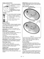
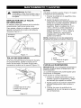
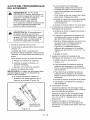
GENERAL LUBRICATION
IMPORTANT: Wipe each fitting clean before
and after lubrication.
IMPORTANT: DO NOT allow grease or oil to
get on friction disc, friction plate or belts.
NOTE: Apply Stens Mix Hi-Temp Grease or
equivalent to the lubrication fittings. See
Service Parts.
Sno-Thro should be lubricated (Figure 10) at
beginning of season or every 25 operating
hours.
Auger
\
OS1373
Grease
Oil
Figure 10
Shaft
NOTE: To grease auger shaft, remove shear
bolt nuts, and shear bolts. Turn auger on shaft
while applying grease at zerk fittings. Replace
shear bolt per instructions in Service and
Adjustments.
GB- 19
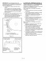
,t_
2. Adjust runners by inserting a spacer of
desired thickness under center of scraper
blade, loosen runner hardware, slide
runners to flat surface. Allow 1/8 in.
(3 mm) between scraper blade and hard
smooth surfaces. Allow 1-1/4 in. (30 mm)
between scraper blade and uneven or
gravel surfaces. Retighten hardware.
WARNING: AVOID INJURY. Read
and understand the entire Safety
section before proceeding.
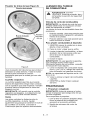
DISCHARGE CHUTE DEFLECTOR
Deflector must stay in selected position while
throwing snow.
NOTE: Keep housing level by adjusting
runners equally.
To adjust, loosen then retighten hardware to
desired deflector drag force (Figure 11).
Adjusting
Hardware
1
Discharge Chute
Deflector
Figure 11
1. Runner
2. Runner Hardware
OS0486
Figure 13
©S0113
DISCHARGE CHUTE
SCRAPER BLADE
If chute does not stay in position while
operating, tighten nut on carriage bolt at pivot
)oint to increase tension on spring (Figure 12).
IMPORTANT: Damage to auger/impeller
housing will result if blade wears down too far.
Scraper blade is adjustable to compensate for
wear.
To adjust scraper blade:
1. Tip unit back onto handlebar, support
housing and loosen nuts retaining blade.
2. Adjust runners to fully raised position
(housing closest to ground).
3. Reposition scraper blade flush with
runners and tighten lock nuts.
2 3
SHEAR BOLTS
4
OS0115
1.
2.
3.
4.
Pinion
Chute Gear
Carriage Bolt
Spring
Figure 12
RUNNERS
Runners should be adjusted as conditions
require (Figure 13).
1. Position unit on a hard, flat, smooth level
surface.
IMPORTANT: Use only Ariens shear bolts for
replacement. Use of any other type of shear
bolt may result in severe damage to unit.
Occasionally a foreign object may enter the
auger/impeller housing and jam the auger,
breaking shear bolts (Figure 14) which secure
the auger to the shaft. This allows auger to
turn freely on the shaft preventing damage to
gear drive.
For Replacement:
1. Slide auger outward against roll pin and
align hole in shaft with hole in auger
(holes in shaft for roll pins and shear bolts
line up).
GB - 20
2.Drive
shear
boltthrough
hole(ifshear
bolt
wasbroken
thiswilldrive
remaining
part
fromshaft).
3.Secure
shear
boltwithnut.
8. Adjust pivot pin as needed so unit travels
forward when speed selector lever is in
first forward position and backward when
speed selector lever is in first reverse
position.
9. Secure adjustment pivot pin to speed
selector lever with hairpin.
ii
U
1
2
OS0402
1.Auger
2. Shear Bolt(s)
3. Roll Pin
1
Figure 14
0Ss0195
SPEED SELECTOR ADJUSTMENT
1. Shift Rod
To adjust (Figure 15):
2. Adjustment Pivot Pin
3. Speed Selector Lever
4. Hair Pin
1. Remove hair pin from adjustment
pin.
pivot
Figure 15
2. Pull shift rod and adjustment pivot pin out
of speed selector lever.
3. Place the speed selector lever in the
fastest forward speed position.
4. Pull the shift rod straight down towards
the ground as far as it will go.
5. Thread the adjustment pivot pin along the
shift rod until it aligns with the mating hole
on the speed selector lever.
6. Reinsert the pivot pin into the hole on the
speed selector lever.
7. Check forward and reverse speeds.
a. Start unit.
b. Shift speed selector into first forward
speed.
c. Engage traction clutch. Unit should
move forward.
d. Stop unit.
e. Shift speed selector into first reverse
speed.
f. Engage traction clutch. Unit should
move backward.
g. Shut off unit.
GB -21
ATTACHMENT DRIVE BELT
REPLACEMENT
Remove
Attachment
Drive
7
Belt
(Figures 16 and 17)
1. Shut off engine, remove key, disconnect
spark plug wire and allow unit to cool
completely.
2. Remove two screws securing belt cover
to unit and remove belt cover.
3. Remove spring pin from chute crank rod
assembly and separate.
4. Remove hardware holding chute strap to
engine and lift discharge chute off
housing.
5. Remove belt finger by removing cap
screws mounting belt finger to engine
(Figure 17).
6. Remove attachment drive belt from
engine sheave (it may be necessary to
turn engine sheave using recoil starter
handle).
CAUTION: Always support
Sno-Thro frame and housing when
loosening the cap screws holding
them together. Never loosen cap
screws while unit is in service
position.
IMPORTANT: To avoid bending bottom cover,
when tipping unit apart, support handlebars
firmly or tip unit up on housing and remove
bottom cover by removing four cap screws
before separating unit.
7. Support Sno-Thro frame and housing.
8. Remove top two cap screws and loosen
lower cap screws holding blower housing
to frame (one on each side).
9. Separate housing from unit. Lower
handlebar on floor.
10. Remove attachment drive belt from lower
pulley (hold brake away from belt).
8/
1. Housing Bolt
Holes
2. Belt Cover
3. Pinion and Gear
4. Spring Clip Pin
5. Chute Crank
6. Chute Strap
7. Chute Strap
Mounting
Hardware
8. Bottom Cover
Figure 16
Replace
Attachment
Drive
os0803
Belt
1. Place new belt onto lower pulley and
while holding brake out of way, tip unit
together.
2. Secure blower housing to frame with cap
screws.
3. Place belt onto engine sheave.
4. Make sure engine sheave and
attachment pulley align. If alignment is
necessary, loosen engine sheave set
screws, reposition sheave and retighten
set screws.
5. Replace belt finger.
IMPORTANT: BELT FINGER MUST BE
between 1/16 to 1/8 in. (1.6-3 mm)from belt
with attachment clutch engaged or belt
grabbing may occur causing impeller to rotate
while attachment clutch is disengaged
(Figure 17).
6. Adjust clutch per Attachment Clutch/
Impeller Brake Adjustment below.
7. Reinstall chute strap and mounting
hardware onto engine.
8. Replace chute crank and secure with
spring pin.
9. Replace belt cover and secure with cap
screws.
GB - 22
5
6
1. Attachment
Idler
Belt
2. Belt Finger
3. Attachment Drive
Belt
4. Traction Drive Belt
5. Camshaft Pulley
6. Engine Sheave
7. Traction Belt Idler
8. Attachment
9. Attachment
Nut
Pulley
Idler
OS0464
Figure
17
TRACTION DRIVE BELT
REPLACEMENT
NOTE: Housing and frame must be tipped
apart and attachment drive belt removed from
engine sheave in order to change traction
drive belt (Figures 16 and 17).
A
CAUTION: Always support SnoThro frame and blower housing
when loosening the cap screws
holding them together. Never loosen
cap screws while unit is in service
position.
NOTE: To gain clearance, engage traction
clutch and if necessary pull back attachment
idler arm clevis pin.
3. Replace traction drive belt making sure
pulleys align. If alignment is necessary,
loosen camshaft pulley set screws,
reposition pulley and retighten set
screws.
4. Replace attachment drive belt (See
Replace Attachment Drive Belt).
1. Remove attachment drive belt (See
Remove Attachment Drive Belt).
2. Pull idler away from traction drive belt and
remove belt from idler, camshaft pulley
and driven pulley (it may be necessary to
turn camshaft pulley using recoil starter
handle).
GB - 23
ATTACHMENT
ADJUSTMENT
CLUTCH/BRAKE
b.With the clutch bail disengaged,
loosen the control cable mounting nuts
on the attachment clutch arm
(Figure 21).
WARNING: IMPROPER
ADJUSTMENT could result in
unexpected movement of auger and
impeller causing death or serious
injury. AUGER / IMPELLER MUST
STOP within 3 seconds when
Attachment Clutch/Impeller Brake
Bail is released.
c. Pull up on the cable body to remove
cable slack.
d. Finger tighten mounting nuts and then
loosen the top nut five turns.
e. Tighten the bottom nut with a wrench.
4. Check attachment clutch bail
measurement.
a. Start engine and run at full throttle.
b. Slowly squeeze the attachment clutch
bail until auger shaft begins to rotate.
c. Measure the distance from the end of
the clutch bail to the handlebar as
shown in Figure 20. The distance
between the clutch bail and the
handlebar should be 3-1/2 + 1/8 in.
(8.9 cm + 3 mm).
WARNING: Adjustment procedure
requires the engine to be run with
the belt cover off. AVOID INJURY.
Read and understand the entire
Safety section before proceeding.
1. Remove belt cover.
2. Check belt alignment (Figure 17).
Engine sheave and attachment pulley
must align vertically. Also, belt must be
centered in the idler pulley.
d. Shut off engine.
5. Adjust attachment clutch bail
measurement, if necessary.
To align, move engine sheave:
a. Loosen set screws.
a. Loosen idler nut (Figure 17).
b. To increase distance between clutch
bail and handlebar, move the idler
towards the attachment belt.
b. Slide sheave and key to desired
position.
c. Tighten set screws.
c. To decrease the distance between the
clutch bail and handlebar, move the
idler away from the attachment belt.
3. Adjust cable slack.
IMPORTANT: The clutch cable must be slack
when clutch bail is disengaged.
a. Center the upper cable adjuster on the
mounting bracket, if necessary
(Figure 17).
d. Tighten idler adjustment nut.
e. Check clutch bail measurement.
6. Check Brake
When the clutch bail is disengaged, the
brake must contact the attachment belt.
When the clutch bail is engaged, the
brake must be more than 1/16 in.
(1.6 mm) away from the belt (Figure 19).
7. Repeat steps 3-6 until attachment clutch
bail distance and brake contact are
correct.
IMPORTANT: If attachment clutch/brake
cannot be adjusted within tolerances, see your
Dealer for repairs.
8. Check belt finger clearance.
With clutch bail engaged, belt fingers
should be 1/16-1/8 in. (1.6 - 3.0 mm)from
belt. Adjust belt fingers as necessary.
Upper Cable
Adjuster
Figure 18
9. Replace belt cover.
©$2460
10. Check that auger/impeller stops within
3 seconds after attachment clutch/
impeller brake bail is released.
GB - 24
To adjust traction clutch (Figure 21):
1. Loosen jam nut on traction cable
adjustment barrel.
2. Turn adjustment barrel up the cable to
decrease the distance between clutch bail
and handlebar.
Turn the adjustment barrel down the cable
to increase the distance between clutch
bail and handlebar.
3. Check traction clutch bail distance and
repeat adjustment steps if necessary.
1/16in.
(1.6mm)
1.Drive
Brake
2.Brake
Shoe
andPad
4. Tighten jam nut on traction cable
adjustment barrel.
OS2030
j5
Figure
19
2-1/8 + 3/8 in.
(5.4 cm + 9 mm)
3-1/2 + 1/8 in.
(8.9 cm + 3 mm
7
Traction Drive
Clutch Bail
1. Traction Clutch
Cable
2. Shift Rod
3. Attachment
Control Cable
Attachment
Clutch Bail
4. Mounting Nuts
5. Attachment
Clutch Arm
Figure 20
OS0523
6. Speed Selector
Arm
7. Cotter Pin and
Clevis
8. Traction Drive
Clutch Arm
9. Adjustment
Barrel
OS2490
Figure 21
TRACTION DRIVE CLUTCH
ADJUSTMENT
If drive slips, adjust traction clutch to
compensate for friction disc wear.
To test traction clutch (Figure 20):
1. Put unit in first forward speed.
2. Without engine running, push unit forward
while slowly moving the traction drive
clutch bail toward the handlebar.
3. Measure distance between bail and
handlebar when the wheels begin to
brake. If distance is not 2-1/8 + 3/8 in.
(5.4 cm + 9 mm), adjust the traction
clutch.
GB - 25
FRICTION DISC REPLACEMENT
4
11
9. Remove bearing cap/bushing
from right side of unit.
and washer
10. Reinstall nuts on screws through side
frame to keep screws in place.
11. Carefully tap two (2) roll pins out of center
and right end of shaft.
12. Slide friction disc assembly and hex shaft
to the right until the left end of shaft is
clear of left bearing. Tap lightly if
necessary, to loosen. The shaft slides out
of the small pinion gear and washer.
13. Carefully lift shaft and friction disc out of
unit. As you remove the assembly, the
washers between the bearing and sliding
forks will be loose. Do not lose the
washers.
Replace
\
10
6
1. Hex Shaft
2. Friction Disc
3.
4.
5.
6.
7. Bearing Cap
Screws
Hex Bolts & Nuts
Shift Carrier
Roll Pins
Washers
8. Bearing Cap/
Bushing
9. Clutch Fork
1&Large Gear
11.Pinion Gear
Figure 22
Remove
Friction
os2002
Disc
(Figure 22):
1. Shut off engine, remove key, disconnect
spark plug wire and allow unit to cool
completely.
Friction
Disc
1. Remove three (3) hex bolts and nuts
holding friction disc to shift carrier.
2. Remove the old friction disc. Put the new
friction disc in place, flat side to the shift
carrier.
3. Reinstall the three (3) bolts and nuts into
the new friction disc and hub. Torque to
5-6 Ibf-ft (6.8 to 8.13 N°m).
Reinstall
Friction
Disc
1. Reinstall the shift carrier, the small pinion
gear and washer onto the hex shaft. The
washer goes between the bearing and the
pinion gear.
2. Slide the shaft and attached parts into the
frame, through the right side hole first,
then the left. Pinion gear must mesh with
the large gear.
3. Reinstall the bearing and outside bearing
cap on the left side of the frame.
,_
CAUTION: Before tipping unit,
remove enough fuel so that no spills
OCCUr.
2. Tip the unit up onto front housing on a
level surface.
4. On the right side of the frame, place the
washer on the end of the shaft.
5. Reinstall the bearing cap/bushing
right side of frame.
on the
3. Remove Iockpins from wheel axles and
remove wheels.
6. Reinstall the flange bearing and washers
into the shift forks. Be sure the washers
are inside the forks.
4. Remove two (2) bolts from top of bottom
cover.
7. Reinstall roll pins in shaft. Be sure pins
are centered in shaft.
5. Loosen two (2) bottom screws and slide
cover off.
8. Reinstall shift rod with hairpin and
washer.
6. Remove hair pin and washer from shift
rod. Disconnect shift rod from speed
selector arm. Reinstall hairpin and
washer on rod.
9. Reinstall tires with Iockpins.
10. Install bottom cover.
7. Remove four (4) nuts from bearing cap on
left side of unit.
12. Replace spark plug wire on spark plug.
11. Set unit upright.
8. Reinstall one nut to keep the inside
bearing cap in place.
GB - 26
,_
WARNING: AVOID INJURY. Read
and understand the entire Safety
section before proceeding.
SHORT TERM
IMPORTANT: NEVER spray unit with high
pressure water or store unit outdoors.
Run with attachment clutch engaged a few
minutes after each use to free unit of any loose
or melting snow.
Close fuel shut-off valve.
Inspect unit for visible signs of wear, breakage
or damage.
Order the following parts through your
Dealer:
Part No.
Description
00036800
Stens Mix Hi-Temp Grease
(3, 3 oz. cartridges)
21533400
Spark Plug (932036, 504)
21533500
Spark Plug (932037, 505)
07219100
Impeller Belt (932036, 504)
07232500
Impeller Belt (932037, 505
07210600
Traction Belt (932036, 504)
Keep all nuts, bolts and screws properly
tightened and know unit is in safe working
condition.
07210700
Traction Belt (932037, 505)
53200500
Shear Bolts
Store unit in a cool, dry protected area.
03248300
Friction Disc
LONG TERM
Clean unit thoroughly with mild soap and low
pressure water and lubricate (see
Maintenance). Touch up all scratched painted
surfaces.
To obtain a complete parts manual, find your
model and serial number. Then go to
www.ariens.com or call 1-800-678-5443.
Remove weight from wheels by putting blocks
under frame or axle.
When storing unit for extended periods of
time, remove all fuel from tank and carburetor
(run dry). Refer to Engine Manual.
See your authorized Ariens dealer to add the
additional accessories available to your
Sno-Thro.
Part No.
Description
73203100
Slicer Bar*
72200600
120 Volt Starter Kit
73202500
240 Volt Starter Kit*
72406500
Front Weight Kit*
*Available in CE countries.
GB - 27
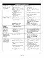
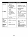
/i_(oll]__oIo_
PROBLEM
Engine will not
crank/start.
Engine stops.
PROBABLE
CAUSE
CORRECTION
1. Fuel tank is empty.
2. Fuel shut-off valve closed.
1. Fill fuel tank.
2. Open fuel shut-off valve.
3. Build up of dirt and residue
around governor/
carburetor.
3. Clean area around governor/
carburetor.
4. Key Switch not in run
position.
5. Electric starter not
functioning.
4. Put Key Switch into run position.
1. Out of fuel.
2. Fuel shut-off valve closed.
5. Check for a bad starter or
connections.
1. Fill fuel tank.
2. Open fuel shut-off valve.
3. Mechanical jam in blower
rake or impeller.
3. Turn off engine, remove key, and
wait for all moving parts to stop.
Check for and remove
obstruction and repair before
restart.
4. Polluted fuel supply.
4. Replace with clean fuel.
5. Faulty spark plug.
5. Replace or clean spark plug.
Engine
problems.
1. See Engine Manual.
Does not
operate in
Forward/
Reverse.
1. Friction disc not adjusted
properly.
2. Traction belt not
functioning.
1. Repair or replace
See Friction Disc
2. Repair or replace
belt. See Traction
Replacement.
Small rubber
beads collect
in frame.
1. Friction disc wear.
1. Normal friction disc wear.
Chunks or large pieces of rubber
mean friction disc should be
checked and replaced as
necessary.
Unit throws
snow poorly
or does not
throw snow.
1. Shear bolts broken.
1. Replace shear bolts (see Shear
Bolts).
2. Move unit to a warm area to
thaw.
2. Auger is frozen in place.
friction disc.
Replacement.
traction drive
Drive Belt
3. Ice or debris is obstructing
auger.
3. With engine off, and auger
disengaged, check for
obstructions and remove.
4. Attachment clutch/brake
out of adjustment.
4. Adjust attachment clutch/brake.
See Attachment Clutch/Brake
Adjustment.
5. Attachment
slipping.
5. Adjust or replace attachment
drive belt. See Attachment Drive
Belt Replacement,
drive belt
GB - 28
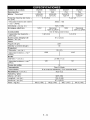
[,,,,___o]_,,,_
Model Number
Description
Engine - Tecumseh
932036
932504
932037
524
524
724
724
HSSK5067416U
HSSK5067417U
OHSK7072517F
OHSK7072507F
5.O (3.73)
Power Max - HP (Kw/min q)
Fast Idle Speed-RPM (min q)
DisplacementElectric
7 (5.22)
3600 + 150
in. (cc)
Start
932505
11.88 (195)
120V
Optional
120V or 240V
Fuel
120V
Optional
120V or 240V
See Engine Manual
Tank Capacity - qt. (L)
Snow Clearing
in. (cm)
Chute
2 (1.96)
3.5 (3.3)
Width -
24 (61.0)
Rotation Angle
Rotation Control at
Handlebar
220 °
Yes
Impeller
Diameter-
in. (cm)
Speed-RPM-Max
10 (25)
(min q)
1200
1410
Auger
Diameter -in. (cm)
Speed-RPM-Max
Auger
Drive
11.0 (27.98)
(min q)
120
141
Brake
Yes
Disc-O-Matic
Speeds
Pneumatic
6 Forward and 2 Reverse
Tires -in. (cm)
12 (30.5)
Size and Weight
Height - in. (cm)
38 (96.5)
Length -in. (cm)
49 (124.5)
Width - in. (cm)
Weight-lbs(Kg)
26.5 (67.3)
150(68.0)
I
146(66.2)
GB - 29
I
147(66.7)
I
143(64.9)
3-Year Limited
Sno-Thro
Warranty
Ariens Company warrants to the original purchaser that consumer products manufactured
by Adens Company will be free from defects in material and workmanship for a period
of three (3) years after the date of purchase, and wilt repair any defect in material or
workmanship, and repair or replace any defective part, subject to the conditions, limitations
and exclusions set forth herein.
Ariens Company
655 West Ryan Street
P.O. Box 157
Briliion, Wt 54110-0157
920-756-2141
Fax 920-756-2407
'¢¢¢¢w.ariens.com
The three-year duration of this warranty applies only if the product is put to ordinary,
reasonable, and usual personal, family, or household uses. tf the product is put to any
business, commercial, or industrial use, then the duration of this warranty is ninety (90)
days after the date of purchase, or one (1) year after the date of purchase if the product
is labeled as a Professional/Commercial
Product. tf any product is rented or leased,
then the duration of this warranty is ninety (90) days after the date of purchase.
Genuine Adens service parts and accessories
not purchased with the product covered
by this warranty, but which are later purchased and used with that product, are warranted
to be free from defects in material and workmanship
for a period of ninety (90) days
after date of purchase, and Adens Company will repair or replace any such part or
accessory free of charge, except for labor, during that period.
This warranty
is subject to the following
This warranty
met:
is valid only if the following
conditions,
limitations,
conditions
are
- The purchaser must promptly notify Ariens Company or an
authorized Ariens service representative of the need for
warranty service.
- Returning the product registration card to Ariens Company
will enable the company to contact the registrant with repair
or replacement part information.
items
are not covered
by this warranty:
- Engines and engine accessories are covered only by the
warranty made by the engine manufacturer, and are not
covered by this warranty.
- Parts that are not genuine Adens service
covered by this warranty.
- Shoes, runners, scraper blades, shear botts
bulbs are not covered by this warranty.
is subject
to the following
- The purchaser must transport
place of warranty service.
- The purchaser must perform maintenance and minor
adjustments explained in the owner's manual.
The following
and exclusions:
This warranty
parts are not
headlights, light
- Any defect which is the result of misuse, alteration, improper
assembly, improper adjustment, neglect, or accident is not
covered by this warranty.
limitations:
the product to and from the
- Warranty service must be performed by an authorized Ariens
service representative. (To find an authorized Ariens service
representative
contact Ariens Company at the website,
number or address above.)
- Batteries are warranted only for a period of twelve (12)
months after date of purchase on a prorated basis. For the
first ninety (90) days of the warranty period a defective
battery wilt be replaced free of charge, tf the applicable
warranty period is more than 90 days, Ariens Company wilt
cover the prorated cost of any defective battery, for up to
twelve (12) months after the date of purchase.
- Normal maintenance items including, but not limited to, belts,
idlers, cables, friction wheels, tires, wheels, electrical
components are warranted for a two-year period from the
date of purchase unless a shorter period would apply based
on how the product is used, then the shorter period wilt
apply.
- Products which were not purchased in the United States
Puerto Rico, or Canada are not covered by this warranty. In
all other countries, contact place of purchase.
DISCLAIMER
OF FURTHER
WARRANTY
Ariens Company makes no warranty, express
or implied, other than what is expressly
made
in this warranty. If the law of your state provides
that an implied warranty of merchantability,
or
an implied warranty of fitness for particular
purpose, or any other implied warranty, applies
to Ariens Company, then any such implied
warranty
is limited to the duration
of this
warranty.
Some states do not allow limitations
on how long an implied warranty lasts, so the
above limitation
may not apply to you.
LIMITATION
OF
REMEDY
AND
DAMAGES
Ariens Company's liability under this warranty, and under any
implied warranty that may exist, is limited to repair of any
defect in workmanship,
and repair or replacement d any
defective part. Ariens Corn pany shall not be Liable for incidental,
special, or consequential
damages (including lost profits).
Some states do not allow the exclusion of incidental or
consequential
damages, so the above limitation or exclusion
may not apply to you.
This warranty gives you specific legal rights,
and you may also have other rights which vary
from state to state.
Form:ALW3-122002
GB - 30
Ariens
Company
655West
Ryan
Street
EO.Box157
Brillion,
WI54110-0157
920-756-2141
Fax920-756-2407
www.ariens.com
WARNING
The engine exhaust from this product
contains chemicals known to the State
of California to cause cancer, birth
defects or other reproductive
harm.
Sno-Throo
Owner/Operator
Manual
Models
932036-524
932037-724
932504-524
932505-724
U.S. Patents Pending
_
_
_ENGLISH
FRANQAIS
ESPAKIOL
Transfer
model &
serial number
label from
Coller I'autocollant du
module et du numero de
serie dans cet encadr&
product
registration
here.
Transferir aqui la etiqueta
del modelo y nOmero de
serie del registro del
producto.
03249300C 3/04
Supersedes 03249300,A,B
Printed in USA
Ariens Company
655 West Ryan Street
RO. Box 157
Brillion, Wisconsin
54110-0157
USA
Telephone:
(920) 756-2141
Facsimile:
(920) 756-2407
MODEL CERTIFICATE OF CONFORMITY ISSUED BY THE
M.ANUFA.CTURER - CERTIFICAT DE CONFORMITE_ DU MODELE
DELIVRE PAR LE FABRICANT - MODELL-KONFORMIT,_,TSBE SCHEINIGUNG AUSGESTELLT DURCH DEN HERSTELLER CERTIFICATO DI COMFORMIT,_ DEL MODELLO RILASCIATO DAL
PRODUTTORE - CERTIFICADO DE CONFORMIDAD DEL MODELO
PROVISTO POR EL FABRICANTE - MODELLSERTIFIKAT
FOR
OVERENSSTEMMELSE
UTSTEDT AV FABRIKANT TILLVERKARENS MODELLCERTIFIKAT OM
OVERENSST,_MMELSE
- VALMISTAJAN ANTAMA VAKUUTUS
MALLIN M.,_,_R,_,YSTEN MUKAISUUDESTA - SWlADECTWO
ZGODNOSCI MODELU WYDANE PRZEZ PRODUCENTA
We the undersigned, ARIENS COMPANY, certify that: - Nous, soussignes ARIENS
COMPANY, certifions que :- Der Unterzeichnete, ARIENS COMPANY, bescheinigt, dass: La sottoscritta societ&, ARIENS COMPANY, certifica che: - Nosotros, los abajo firmantes,
ARIENS COMPANY, certificamos que: - Undertegnede, ARIENS COMPANY, bekrefter at: Undertecknad, ARIENS COMPANY, intygar att: - Allekirjoittanut, ARIENS COMPANY,
vakuuttaa, ett&: - My, nizej podpisani, ARIENS COMPANY, o_wiadczamy, ze:
Type: - Tipo: Tyyppi: - Typ: -
WALK BEHIND SNOW THROWER - LES CHASSE_S-NEIGE
AUTOTRACTES - HANDGEFUHRTE SCHNEEFRASE - SPAZZANEVE
SEMOVENTE - CAMINAR POR DETRAS DE LA LANZADORA DE NIEVE
- SNOFRESER - GA BAKOM SNOSLUNGAN - K,_SINOHJAILTAVA
LUMILINKO - ODGARNIACZ SNIEGU DO PROWADZENIA PRZED SOB,_
Trade Name: - Appellation commerciale : Handelsbezeichnung:
- Nome commerciale:Nombre
comercial:Handelsnavn:Handels-beteckning:Kauppanimi: - Nazwa handlowa:
ARIENS Sno-Thro
Model: - Modele : - Modell: - Modello: - Modelo: - Modell: Modell: - Malli: - Model:
Serial # Range: - Gamme de numeros de Serie : Seriennummern: - Gamma n. di serie: - Rango de n° de serie: Serienummeromr&de:
- Serienummer-omr&de: Sarjanumerot: - Zakres, numer seryjny:
Conforms to: - Conforme & : - Entspricht: - Conforme a: Conforme a: - E ri samsvar med:- Uppfyller: T&ytt&& seuraavat vaatimukset: - Jest zgodny z:
Representative Measured Sound Power Level
(Lwa) - Niveau de puissance acoustique
representatif - Repr&sentativer gemessener
Ger&uschpegel - Livello di potenza sonora
rappresentativo rilevato - Nivel de potencia
act_stica representativo medido Representativt m< lydeffektniv& Representativ uppm&tt Ijudniv& - Edustava,
mitattu &&nen tehotaso - Zmierzony
reprezentatywny poziom mocy akustycznej
932504
932505
> 001000
> 000101
98/37/EC, 89/336/EEC,
92/31/EEC, 2000/14/EC
(V)
Guaranteed Sound Power Level (Lwa) Niveau garanti de puissance acoustique Garantierter Ger&uschpegel - Livello di
potenza sonora garantito - Nivel de potencia
act_stica garantizado - Garantert
lydeffektniv& - Garanterad Ijudniv& Taattu &&nen tehotaso - Gwarantowany
reprezentatywny poziom mocy akustycznej
932504:101
dB A
932504:104
dB A
932505:100
dB A
932505:104
dB A
2
Philip
J,Smucker:
Manager
ofProduct
Conformance
(Keeper
ofTechnical
File)
- Responsable
dela
- Firmaconformite
desproduits
(enpossession Signature
UnterschriftSignatu rdudocument
technique)
- Leiter
der
Namnteckning Produkt(Jbereinstimmung
(Verantwortlicher
Allekirjoitus - Podpis
fordietechnische
Dokumentation)
- Addetto
aliaconformit&
delprodotto
(inpossesso
deldocumento
tecnico)
- Gerente
de
conformidad
delosproductos
(enposesi6n
deldocumento
tecnico)
- Ansvarlig
for
3roduktsamsvar
(innehaver
avteknisk
ill)Chef
f6rprodukt6verensst&mmelse
(innehavare
avtekniska
dokument)
Tuotteen
vaatimustenmukaisuudesta
vastaava
johtaja
(teknisen
tiedoston
haltija)
Zarzadzajacy
Zgodno_cia
Produktu
(przechowujatcy
Dokumentacj_
Techniczna)
._
5/21/2003
Date
- Data
Datum
Fecha
- Dato
P&iv&ys
- Data
t _
CE Sound and Vibration - Niveau sonore et vibration CE - CE-Ger&uschpegel
und Vibrationswerte - Livello sonoro e vibrazioni CE - Sonido y vibraci6n CE CE-lydniv& og Vibrasjonsm&ling - CE Ijudniv& och Vibrations-m&tning CE-melutaso T&rin& - CE D:_wi_ku i Wibracji
Model: - Modele : - Modell: - Modello: - Modelo: - Modell: - Modell: Malli: - Model:
932504
932505
Oper. Ear Sound Pressure (Lpa) in dB A- Pression acoustique Pression
sonore aux oreilles de I'op@ateur (Lpa) en dB A - Ger&uschst&rke am Ohr
des Bedieners (Lpa) in dBA - Potenza sonora percepita dall'operatore
(Lpa) in dB A - Presi6n de sonido en el oido (Lpa) in dB A - Lydtrykk i
fererens {)re (Lpa) in dBA - Vid f6rarens position (Lpa) i dB A - Kuljettajan
korvaan kohdistuva &&nipaine (Lpa)/dB A- Robocze ci_nienie akustyczne
na uchu (Lpa) w decybelach A
88
88
Vibration Measure (m/sec 2) @ Operator Hands - Niveau de vibration aux
mains de I'op@ateur - Vibrationswerte An den H&nden des Bedieners Misura delle vibrazioni alle mani dell'operatore - Cantidad de vibraci6n en
las manos del operador - Vibrasjonsm&ling ved brukerens hender Vibrationsm&tning vid f6rarens h&nder - T&rin& kuljettajan k&siss& Pomiar wibracji na rCkach operatora
X
8.3
4.1
Y
3
1.6
Z
4.9
2.6
ENGLISH
ESPANOL
FRAN(_AIS
1.Traction
Drive
Clutch
Bail 1.Levier
d'embrayage
de
1.Palanca
delembrague
I'entrafnement
dela
delatransmisiSn
dela
2.Speed
Selector
traction
tracciSn
3.Chute
Crank
devitesses 2.Selector
develocidad
4.Muffler
Guard
(932504, 2.Selecteur
delatolva
505)
3.Manivelle
delagoulotte 3.Manivela
4.Garant
dusilencieux 4. Protector
delsilenciador
5.Discharge
Chute
Deflector
(932504,
505)
(932504,
505)
delatolva
de
6.Discharge
Chute
5.Deflecteur
delagoulotte 5.Deflector
d'evacuation
7.Impeller
descarga
6.Goulotte
d'evacuation 6.Tolva
8.Auger
dedescarga
7.Turbine
9.Auger
Gearcase
7.Propulsor
8.Rotor
8.Sinfin
10.Scraper
Blade
9.Boftier
derenvoi
durotor 9.Cajadeengranajes
11.OilFillandDipstick
del
10.Lame
racleuse
sinfin
12.GasTank
andCap
13.Recoil
Starter
Handle 11.Tube
deremplissage
en 10.Cuchilla
raspadora
14.Electric
Starter
(932036, huile
etjauge
11.Llenado
deaceite
y
12.Reservoir
decarburant
varilla
medidora
037)
15.Primer
Bulb
etbouchon
12.DepSsito
degasolina
dudemarreur
16.Throttle
(Engine
Stop) 13.Poignee
ytapa
cordon
17.Ignition
Switch
13.Manilla
dearranque
de
14.Demarreur
electrique
retroceso
(push-pull)
18.Choke
14.Arranque
electrico
(932036,
037)
19.Spark
Plug
andWire
15.Poire
d'amor£age
(932036,
037)
15.Perilla
decebado
20.Runner(s)
16.Commande
desgaz
21.BeltCover
(arr6t
dumoteur)
16.Acelerador
(parada
de
22.J-Bolt
17.Cledecontact
motor)
23.Handlebar
17.Interruptor
deencendido
(pousser-tirer)
24.Attachment
Clutch
Bail 18.Starter
(tiro-empujel)
25.FuelShut-off
Valve
18.Estrangulador
19.Bougie
etfil
26.AxleLock
Pin
19.Bujiaycable
20.Patin(s)
21.Couvercle
ducourroie 20.Guia(s)
22.VisenJ
21.Cubierta
delacorrea
23.Guidon
22.Perno
enJ
24.Levier
d'embrayage 23.Manillar
deI'outil
24.Palanca
delembrague
25.Robinet
decarburant
delaccesorio
25.Valvula
decorte
del
26.Broche
deblocage
de
I'essieu
combustible
26.Pasador
detraba
deleje
6
7
10
20
9
19
11
12
17
18
13
14
16
15
0S2420
Figure 1
0S0503
D_o]_i i :l_llmIo]
Controles
Seguridad
Montaje
y caracteristicas
............
..........................
...........................
Funcionamiento
....................
4
Almacenamiento
8
Resoluci6n
13
Piezas de repuesto
15
Accesorios
......................
20
Especificaciones
Mantenimiento
y ajustes
22
Garantia
EL MANUAL
Antes de poner en funcionamiento la unidad,
leer y comprender los manuales atentamente.
Si se usa incorrectamente, esta unidad puede
ser peligrosa y causar lesiones personales o
daSos a la propiedad. El contenido le
proporcionara las instrucciones acerca del
funcionamiento seguro de la unidad durante
un funcionamiento y mantenimiento normal.
Todas las referencias a la izquierda, derecha,
adelante o atras se dan asumiendo que el
operador este colocado en posiciSn de
funcionamiento y orientado en la direcciSn de
avance.
MODELO Y NOMEROS DE SERIE
AI pedir piezas de repuesto o al hacer
preguntas sobre mantenimiento, conocer los
nQmeros de modelo y de serie de la unidad y
del motor.
Los nQmeros aparecen en el formulario de
registro del producto del paquete de
informaci6n de la unidad. Estan impresos
sobre la etiqueta del nQmero de serie, situada
en el chasis de la unidad.
Etiqueta del
nQmero de serie
............
..................
.........................
Mantenimiento
.............
....................
de problemas
....................
...........................
29
30
31
31
32
33
• Anotar aqui el modelo y los nQmeros de
serie de la unidad.
• Anotar aqui el modelo del motor y el
nQmero de serie.
REGISTRO DEL PRODUCTO
El concesionario Ariens debe registrar el
producto en el momento de la compra.
Registrar el producto, permite que la
compaSia pueda procesar las reclamaciones
de garantia o ponerse en contacto con el
cliente con la informaci6n sobre
mantenimiento mas actualizada. Seran
aceptadas todas las reclamaciones que
cumplan con los requisitos dentro del periodo
de garantia limitado aunque no se haya
devuelto la tarjeta de registro del producto.
Conservar el comprobante de compra si no se
registra la unidad.
Nota al cliente: Si el concesionario no
registra el producto, favor de completar, firmar
y remitir la tarjeta de registro del producto a
Ariens o bien conectarse a w_v.ariens.com.
PIEZA8 DE REPUESTO
NO AUTORIZADA8
Figura 2
Utilizar solamente piezas de repuesto Ariens.
El reemplazo de cualquiera de las piezas de
este vehiculo con una pieza diferente de las
piezas de repuesto autorizadas por Ariens
puede repercutir negativamente en el
rendimiento, durabilidad o seguridad de esta
unidad y puede anular la garantia. Ariens
renuncia a la responsabilidad por
reclamaciones o daSos, bien sea con respecto
a la garantia, daSos a la propiedad, lesiones
personales o muerte debido al uso de piezas
de repuesto no autorizadas.
©S0522
E-6
© Copyright 2003 Ariens Company
Para
obtener
unabreve
listadelaspiezas
de
repuesto,
consultar
Piezas de repuesto en
este manual. Para obtener un manual
completo de piezas, encontrar el modelo y el
nQmero de serie. A continuaci6n ira
www.ariens.com o Ilamar al 1-800-678-5443.
NOTA: Para Iocalizar el concesionario Ariens
mas pr6ximo, Ilamar al 1-800-678-5443 o ira
www.ariens.com a traves de internet.
,_
ADVERTENClA:
El montaje o ajustes
incorrectos pueden causar lesiones
graves.
RENUNCIA
Ariens se reserva el derecho a interrumpir,
cambiar y mejorar a sus productos en
cualquier momento sin aviso ni obligaci6n al
pQblico. Las descripciones y especificaciones
que contiene este manual se aplicaban en el
momento de la impresi6n del mismo. El
equipo descrito en este manual puede ser
opcional. Algunas ilustraciones pueden no ser
aplicables a su unidad.
2. Comprender todas las precauciones de
seguridad indicadas en los manuales.
3. Repasar las funciones de control y el
funcionamiento de la unidad. No porter en
funcionamiento el Sno-Thro a no ser que
todos los controles funcionen segen se
describe en este manual.
4. Repasar las recomendaciones de
lubricaci6n, mantenimiento y ajustes.
ENTREGA
5. Repasar la p61iza de la garantia limitada.
Nota para el usuario: Si ha comprado este
producto sin el montaje o las instrucciones
completas por parte del vendedor, es
responsabilidad del operador:
6. Completar la tarjeta para registrar el
producto y regresarla a Ariens Company,
o bieR conectarse a www.ariens.com.
1. Leer y comprender todas las
instrucciones de montaje en este manual.
Si no se comprenden o es dificil seguir
las instrucciones, ponerse en contacto
con el concesionario Ariens mas cercano
para recibir asistencia. Asegurarse de
que todo el montaje se haya acabado de
hacer correctamente.
E-7
ANOTACIONES
ADVERTENClA:
Para
evitar
lesiones NOTA: Informaci6n de referencia en general
enlasmanos
yenlos
pies,
siempre
para el funcionamiento y practicas de
desactivar
losembragues,
apagar
el
motor
yesperar
aquesedetenga mantenimiento correctos.
todoelmovimiento
antes
de
IMPORTANTE: Procedimientos o informaci6n
especificos requeridos para evitar daSos a la
desatascar
odetrabajar
enel
unidad o al accesorio.
lanzador
denieve.
Mantener
lasmanos
ylospies
PRACTICAS Y LEYES
alejados
delsinfin
y delpropulsor.
iAtencibn!
Practicar las precauciones de seguridad de
trabajo normales y de costumbre, por el bien
del operador y de los demas. Entender y
seguir todos los mensajes de seguridad. Estar
alerta ante condiciones inseguras y la
posibilidad de lesiones leves, moderadas,
graves e incluso la muerte. Conocer las reglas
y leyes aplicables en la zona. Siempre seguir
las practicas descritas en este manual.
iConciernen la seguridad
personal!
FORMACION NECESARIA
DEL OPERADOR
SiMBOLOS DE SEGURIDAD
Buscar estos simbolos
informarse sobre las
para
precauciones,de seguridad
importantes. Estas significan:
iEstar alerta!
iObedecer
el mensaje!
Los simbolos de alerta de seguridad de arriba
y las palabras de abajo se usan en
calcomanias yen este manual. Leer y
entender todos los mensajes de seguridad.
,_
PELIGRO: INMINENTE!
iSITUACION SiDE
PELIGRO
no se
evita, CAUSAR,& lesiones graves o la
muerte.
_
DVERTENClA:
iSITUACION
DE
PELIGRO
POTENCIAU
Si no se
evita, PUEDE CAUSAR lesiones
graves o la muerte.
_
RECAUClON:
iSITUACION
PELIGRO
POTENCIAU
Si no DE
se
evita, PODRiA CAUSAR lesiones
menores o moderadas. Tambien
puede emplearse para alertar sobre
practicas peligrosas.
E-8
El comprador original de esta unidad ha sido
instruido por el vendedor sobre el
funcionamiento seguro y correcto de la
unidad. Si la unidad va a ser utilizada por otra
persona que no sea el comprador original; o si
va a prestarse, alquilarse o venderse,
proporcionar SIEMPRE este manual y el
entrenamiento de seguridad necesario antes
de ponerla en funcionamiento.
CALCOMANiAS DE SEGURIDAD Y
EMPLAZAMIENTOS
Cambiar SIEMPRE
seguridad da_adas
Ver la figura inferior
las calcomanias de
las calcomanias de
o reponer las que falten.
sobre las ubicaciones de
seguridad.
Figura
3
©$2440
1.iADVERTENCIA!
operador.
Leer el manual del propietario/
0L4370
0L180I
Usar protecci6n para los oidos.
0L4690
0L4010
terceros o articulos que se
pudieran
o daSar
No dirigir lesionar
la descarga
haciaa
causa de objetos lanzados.
Mantener a terceros alejados de
la unidad durante el
funcionamiento de la misma.
Mantener a los niSos fuera del
area de trabajo y bajo la
supervisi6n de un adulto
responsable.
Parar el motor y quitar la Ilave del
encendido antes de dejar el
asiento del operador por
cualquier causa. Leer el manual
del operador antes de realizar el
mantenimiento.
2. iPELIGRO!
0L0910
el motor y sacar la Ilave antes de
despejar. El propulsor gira a
gran
velocidad
debajo Detener
de la
PIEZAS
GIRATORIAS!
abertura de descarga. Esperar
os2070 a que se detengan las piezas
en movimiento antes de extraer
residuos 0 realizar el
mantenimiento.
E-9
Mantener el area de operaci6n libre de
juguetes, mascotas y residuos. Los objetos
que salen despedidos pueden causar
lesiones.
3. iPELIGRO!
PIEZAS GIRATORIAS!
Mantenerse alejado del sinfin
mentras que el motor este en
marcha.
Evitar lugares blandos o movedizos en diques,
rampas o en el suelo. Evitar las areas de
trabajo irregulares y cualquier terreno
accidentado. Mantenerse alerta ante los
peligros ocultos.
• Leer el manual del operador.
• Dejar solamente que adultos
con experiencia operen la
maquina, nunca ni_os.
• Parar el motor y quitar la
Ilave del encendido antes de
dejar el asiento del operador
por cualquier causa.
• Mantener todos los
controles, guardas y
dispositivos de seguridad en
buen estado de
funcionamiento.
• No dirigir la descarga hacia
terceros o articulos que se
pudieran lesionar o daSar a
causa de objetos lanzados.
Evitar el terreno irregular o accidentado. NO
operar cerca de declives abruptos, zanjas o
terraplenes. La unidad puede volcarse
repentinamente si una de las ruedas queda
sobre el borde de una zanja o terraplen o si se
hunde un borde.
La nieve, neblina, etc. pueden reducir la visi6n
y provocar un accidente. Operar la unidad
s61o cuando haya buena luz y visibilidad.
Solamente deben operar esta unidad adultos
capacitados.
La capacitaci6n incluye el hacer funciona la
unidad realmente.
REGLAS DE SEGURIDAD
Leer, entender y seguir todas las practicas de
seguridad del manual del propietario!operador
antes de comenzar a montarlo o a usarlo. El
no seguir todas las instrucciones con cuidado
puede causar graves lesiones y!o daSos a la
unidad.
SlEMPRE quitar la Ilave y!o el cable de la
bujia antes del montaje, el mantenimiento o el
servicio. El arranque no intencionado del
motor puede ocasionar la muerte o lesiones
graves.
Realizar una inspecci6n general del area de
trabajo y de la unidad para entender:
• El area de trabajo • Su unidad • Todas las
calcomanias de seguridad
Comprobar SlEMPRE con cuidado los
espacios libre superiores y laterales antes de
operar la unidad. Cuando se opere en calles o
curvas, estar SlEMPRE atento al trafico.
Mantener alejados a niSos y a terceras
personas. Mantener a los niSos fuera del area
de trabajo y bajo la supervisi6n de un adulto
responsable.
NUNCA dejar que los niSos operen o jueguen
en o cerca de la unidad. Estar alerta y apagar
la unidad si un niSo entra en el area de
trabajo.
NO dejar que adultos sin la formaci6n
adecuada operen la unidad.
NUNCA poner en marcha la unidad durante o
despues de haber consumido medicamentos,
drogas o alcohol. Un funcionamiento seguro
requiere de toda su atenci6n de forma
continua.
NUNCA dejar que una persona que no este
bien alerta o cuya coordinaci6n este afectada
opere esta unidad.
NUNCA poner a funcionar la unidad sin usar
la vestimenta adecuada para el invierno.
Llevar equipo de seguridad adecuado que
incluya gafas de seguridad con protectores
laterales y guantes protectores. Utilizar
calzado adecuado para mejorar la estabilidad
en superficies resbalosas.
NUNCA usar ropa suelta o joyas y atarse el
cabello por el riesgo de que puedan quedar
atrapados en las piezas giratorias.
Protegerse los ojos, la cara y la cabeza de los
objetos que puedan salir despedidos de la
unidad. Usar protecci6n para los oidos.
Evitar los bordes afilados. Los bordes afilados
pueden cortar. Las piezas m6viles pueden
amputar los dedos o una mano.
Mantener las manos y los pies SlEMPRE
alejados de las piezas giratorias durante la
operaci6n. Las piezas giratorias pueden
amputar partes del cuerpo.
NUNCA colocar las manos o parte alguna del
cuerpo o las ropas cerca de las piezas en
movimiento o en el interior de la unidad
mientras esta funcionando.
Mantener SlEMPRE las manos alejadas de
los puntos con riesgo de apretones violentos.
E-10
NOtocarlaspiezas
delaunidad
quepuedan NOexceder
lacapacidad
delamaquina
al
estar
calientes
despues
delaoperaci6n.
Dejar intentar
quitar
lanieve
demasiado
rapido.
quelaspiezas
seenfrien
antes
deintentar NOoperar
aunavelocidad
demasiado
rapida.
realizar
elmantenimiento
olosajustes.
Reducir
lavelocidad
yrealizar
losgiros
Nodirigir
ladescarga
hacia
terceros
uobjetos lentamente.
quepuedan
lesionarse
odaSarse
acausa
de Nooperar
enmarcha
atras
amenos
quesea
objetos
lanzados.
Tener
extremo
cuidado
en absolutamente
necesario.
Retroceder
lassuperficies
degrava.
Mantenerse
alerta SlEMPRE
lentamente.
Mirar
siempre
hacia
porlospeligros
ocultos
oeltrafico.
Ajustar
las abajo
y
detras
antes
dedar
m
archa
atras.
guias
para
quelacuchilla
raspadora
nohaga Desactivar
latransmisi6n
delaccesorio
al
contacto
conlagrava.
desplazarse
deunarea
d
etrabajo
aotra.
NOquitar
lanieve
aunaaltura
mayor
dela
Lasvibraciones
anormales
sonuna
necesaria.
advertencia
deproblemas.
AIgolpear
un
Losmateriales
quesalen
despedidos
pueden objeto
extraSo
sepuede
daSar
launidad.
causar
lesiones
ydaSar
objetos.
Parar
inmediatamente
launidad
yelmotor.
Mantenerse
siempre
alejado
delarea
de
Extraer
laIlave
y esperar
aquetodas
las
descarga
durante
laoperaci6n
deestaunidad.piezas
enmovimiento
sedetengan.
Quitar
el
Losgases
delescape
delmotor
pueden
cable
delabujia.
Revisar
launidad
yrealizar
causar
lesiones
olamuerte.
NOponer
en
todos
losajustes
necesarios
antes
devolver
a
marcha
elmotor
enunarea
cerrada.
Proveer encenderla.
siempre
unabuena
ventilaci6n.
Antes de realizar la limpieza, el
SIEMPRE
desactivar
elaccesorio,
detener
la mantenimiento, reparaciones, etc.:
unidad
yelmotor,
sacar
laIlave
ypermitir
que desactivar el(los) embrague(s), parar la
todas
laspartes
m6viles
separen
antes
de
unidad y apagar el motor, quitar la llave y
abandonar
laposici6n
deloperador.
dejar que todas las piezas en movimiento
se detengan. Dejar que se enfrien las
ELPROPULSOR
GIRATORIO
PUEDE
CAUSAR
LESlONES
GRAVES,
NUNCA piezas calientes.
INTENTAR
DESATASCAR
NILIMPIAR
LA
Dejar en marcha la unidad durante unos
UNIDAD
MIENTRAS
ELMOTOR
ESTE
minutos despues de limpiar la nieve para
FUNClONANDO,
evitar el congelamiento del accesorio.
Leer,
entender
yseguir
todas
lasinstrucciones
Desenganchar el accesorio cuando no se este
enelmanual
yenlamaquina
antes
de
utilizando. Desactivar todos los embragues
arrancar.
antes de arrancar el motor. Ajustar las guias
para despejar de manera segura las
Entender:
superficies con grava o piedra triturada.
• C6mo
hacer
funcionar
todos
los
Nunca dejar desatendida la unidad cuando
controles.
este en marcha. SIEMPRE apagar el motor
• Lasfunciones
detodos
loscontroles. antes de abandonar la unidad. Quitar
• C6mo
PARAR
encaso
deemergencia. SIEMPRE la llave para prevenir su uso no
Antes
dearrancar
elmotor,
desconectar autorizado.
Nunca llevar pasajeros.
el(los)
control(es).
Comprobar con frecuencia el funcionamiento
Utilizar
solamente
alargadores
yreceptaculos
aprobados
alarrancar
unidades
equipadas del embrague y del freno. Ajustar y realizar el
conarranque
electrico.
NOconectar
elcable mantenimiento segQn se requiera. El
movimiento de las ruedas de impulsi6n y del
delarranque
electrico
aningQn
sistema
de
sinfinlpropulsor debe parar rapidamente
cableado
quenoseaunsistema
detres
cuando se sueltan las palancas de control.
cables
contoma
atierra.
NO poner en funcionamiento el cortacesped
SlEMPRE
sedebe
dejar
quelaunidad
yel
motor
seajusten
alatemperatura
ambiente en cuestas empinadas. NO quitar nieve
transversalmente en las pendientes. Avanzar
antes
dequitar
lanieve.
lenta y gradualmente en las pendientes. NO
Siempre
asegurarse
delaposici6n
delos
cambios bruscos de velocidad ni de
pies,
especialmente
aldesplazarse
marcha hacer
Usar una velocidad lenta para evitar
atras
oalabandonar
laposici6n
deloperador.direcci6n.
o cambios en las pendientes. Evitar
Durante
laoperaci6n
sedebe
caminar,
nunca paradas
arrancar o parar en una pendiente.
correr.
E-11
NOestacionar
launidad
enunapendiente
a
Mantener
laboquilla
encontacto
conelborde
menos
queseaabsolutamente
necesario.
AI deldep6sito
degasolina
olaabertura
del
estacionar
enunapendiente,
siempre
recipiente
entodomomento
hasta
quese
bloquear
lasruedas.
termine
deIlenar.
Nousar
undispositivo
para
mantener
laboquilla
abierta.
AItransportar
launidad
enuncami6n
oun
remolque,
SlEMPRE
parar
elmotor,
quitar
la Sisederrama
combustible
enlaropa,
Ilave,
ycerrar
lavalvula
decorte
de
cambiarse
deropa
inmediatamente.
combustible
odrenar
elcombustible.
Antes
deinclinar
launidad
enelalojamiento,
Tener
cuidado
especial
alcargar
odescargarextraer
elcombustible
para
evitar
queocurran
launidad
aodeunremolque
ocami6n.
derrames.
Asegurarse
dequelaunidad
este
ydequenosevolcara
durante
el
Asegurar
elchasis
delaunidad
alvehiculo
de afianzada
mantenimiento.
transporte.
NUNCA
afianzarla
devarillas
o
Mantener
SlEMPRE
lasestructuras
de
articulaciones
quepuedan
da_arse.
protecci6n,
guardas
ypaneles
enbuen
NOtransportar
lamaquina
conelmotor
en
funcionamiento,
ensulugar
yafianzados
de
funcionamiento.
forma
segura.
Nomodificar
niextraer
NUNCA
Mantener
launidad
limpia
dehielo
uotros
deseguridad.
residuos.
Limpiar
losderrames
deaceite
ode losdispositivos
NOcambiar
losajustes
delregulador
del
combustible.
nisobrepasar
lavelocidad
deeste.
Este
producto
estaequipado
conunmotor
de motor
delescape
delmotor
pueden
combusti6n
interna.
NOutilizar
launidad
eno Losgases
lesiones
olamuerte.
NOponer
en
cerca
deningQn
terreno
baldio,
oterrenos
con causar
elmotor
enunarea
cerrada.
Proveer
maleza
oboscosos,
amenos
queelsistema marcha
unabuena
ventilaci6n.
deescape
esteequipado
conunsupresor
de siempre
SlEMPRE
launidad
encondiciones
chispas
quecumpla
conlasleyes
locales, Mantener
estatales
ofederales.
Siseutiliza
unsupresordeoperaci6n
seguras.
Unsilenciador
de
dechispas,
eloperador
debemantenerlo
en escape
daSado
ogastado
puede
causar
un
buenas
condiciones
detrabajo.
incendio
ounaexplosi6n.
todalatornilleria
correctamente
Elcombustible
esaltamente
inflamable
ysus Mantener
vapores
sonexplosivos.
Manipularlo
con
ajustada.
Revisar
lospernos
deseguridad
frecuentemente.
cuidado.
Usar
solamente
envases
para
combustible
aprobados.
Mantener
oreemplazar
lasetiquetas
de
NOfumar,
NOprovocar
chispas,
NOcausar seguridad
einstrucciones
segQn
sea
llamas.
SlEMPRE
dejar
queseenfrie
elmotor necesario.
antes
derealizar
elmantenimiento.
NUNCA
almacenar
launidad
concombustible
NUNCA
Ilenar
eldep6sito
decombustible
con eneldep6sito,
enelinterior
deunedificio
en
elmotor
enmarcha
ocuando
estecaliente. donde
haya
presentes
fuentes
deignici6n.
NUNCA
Ilenar
odrenar
eldep6sito
enun
Cerrar
elpaso
decombustible
ydejar
queel
recinto
cerrado.
motor
seenfrie
completamente
antes
de
oalmacenar
launidad
enunrecinto
Volver
acolocar
eltap6n
delcombustible
con cubrir
mucho
cuidado
ylimpiar
elcombustible cerrado.
derramado.
Para
unalmacenamiento
durante
unlargo
periodo
detiempo,
limpiar
launidad
Nunca
Ilenar
losrecipientes
dentro
deun
Consultar
elmanual
del
vehiculo
osobre
laplataforma
deuncami6n
o completamente.
motor
para
obtener
informaci6n
sobre
el
remolque
conunrecubrimiento
deplastico. almacenamiento
correcto
delaunidad.
Colocar
siempre
losrecipientes
enelsuelo
y
Usar
Qnicamente
aditamentos
oaccesorios
alejados
delvehiculo
antes
deIlenarlos.
diseSados
para
launidad.
Cuando
seaposible,
extraer
delcami6n
o
remolque
elequipo
alimentado
congasolina
y Revisar
loscomponentes
frecuentemente.
Si
Ilenarlo
enelsuelo.
Siestonoesposible, estan
gastados
odaSados,
reemplazarlos
con
entonces
Ilenar
dicho
equipo
enelremolque piezas
recomendadas
porelfabricante.
conunrecipiente
portatil
enlugar
de
directamente
delaboquilla
deundispensador
degasolina.
E-12
ADVERTENClA:
EVITAR
LESIONES.
Antes
deproceder,
leery
comprender
lasecci6n
deSeguridad
completa.
,&
ADVERTENClA:
Si se dejar caer o
volcar la unidad con el embalaje
puede resultar en lesiones personales
o dafios a la unidad.
Herramientas
4. Apretar las perillas de mariposa para
asegurar el manillar superior.
Instalacion
de la tolva de descarga y la
manivela
de la tolva (Figura 5, 6, y 7)
NOTA: Consultar la Figura 5 para los articulos
que se van a instalar en la unidad.
1. Engrasar el asiento de la tolva (si no esta
engrasado).
2. Quitar la tomilleria (y el soporte de la
manivela de la tolva en los modelos
932037 & 505) de la parte superior del
motor (Figura 6).
necesarias:
3. Instalar la tolva de descarga colocando el
aro de la tolva debajo de la presilla de
retenci6n del soporte de asiento.
• Alicates
• Llaves de extremo abierto: 3/8, 7/16, 1/2,
9/16 y/o Ilaves ajustables
• Indicador de los neumaticos
4. Instalar el soporte de la tolva (y el soporte
de la manivela de la misma en los modelos 932037 & 505) en el motor con la tornilleria que se quit6 en el paso 2.
MONTAJE
5. Aflojar la tuerca de montaje en el soporte
de la tolva y mover esta Qltima hacia
arriba o hacia abajo hasta que su aro
quede centrado entre la presilla de retenci6n y el asiento de la tolva. Apretar la tornilleria (Figura 7).
6. Deslizar la manivela de la tolva a traves
del soporte.
Desplegar el manillar
7. Instalar la manivela de la tolva en el pifi6n
con la presilla de resorte.
4
1. Perilla de
3. Manillar inferior
mariposa
2. Pemo en J
4. Manillar superior
4
Figura 4
os3000
1. Tolva de
descarga
2. Presilla con
resorte
1. Aflojar las perillas de mariposa y soltar
los pernos en J del manillar inferior
(Figura 4).
2. Desplegar el manillar superior y alinear
los agujeros del manillar.
3. Colocar los pernos en J a traves de los
orificios del manillar superior e inferior.
3. Manivela de
la tolva
4. Pifi6n
Figura 5
E-13
OS3500
932037,505
932036, 504
I
I
15
61
4
3
5
1
1. Tolva de
descarga
2. Presilla
de retenci6n
3. Tuerca de
montaje
4. Aro de la
tolva
5. Soporte
de
la tolva
Figura 7
Comprobacion
neumaticos
la presion
OS4500
de los
Comprobar la presi6n de los neumaticos y
ajustarla a la presi6n listada en la pared del
neumatico.
Llenar el deposito de combustible del
motor
2
Consultar el manual del motor para el tipo de
combustible correcto y la capacidad del
dep6sito.
1
7
1. Tolva de
descarga
2. Presilla de
resorte
3. Manivela de
la tolva
4. Tornilleria
5. Soporte de
la tolva
6. Soporte de la
manivela de
la tolva
7. Asiento de
la tolva
8. Presilla de
retenci6n
Figura 6
Comprobacion
del aceite
engranajes
del sinfin
Comprobacion del funcionamiento
todos los controles
Asegurarse de que la unidad funciona
correctamente. Consultar Mantenimiento.
Funcionamiento
accesorio
os4ooo
de la caja de
Revisar del nivel del aceite en la caja de
engranajes del sinfin (consultar la secci6n
Mantenimiento y ajustes).
Comprobacion
motor
del aceite
del carter
de
de la correa
del
1. Arrancar la unidad en un area bien
ventilada de acuerdo con Arranque y
apagado en Funcionamiento,
2. Activar la palanca del embrague del
accesorio y dejar funcionar el accesorio
durante aproximadamente
15 minutos.
3. Parar la unidad, esperar a que todas las
piezas en movimiento se detengan, y
extraer el cable de la bujia.
del
IMPORTANTE: Los motores en los modelos
Sno-Thro son enviados sin aceite 5W-30 en el
carter. Consultar el manual del motor para
obtener instrucciones detalladas.
E-14
4. Ajustar el embrague de acuerdo con
Ajuste del freno/embrague del accesorio
en Mantenimiento y servicio.
Palanca del embrague del accesorioPalanca derecha
,_
ADVERTENClA:
EVITAR
LESIONES. Antes de proceder, leer y
comprender la secci6n de Seguridad
completa.
ADVERTENClA:
Para evitar lesiones
en las manos y en los pies, siempre
desactivar los embragues, apagar el
motor y esperar a que se detenga
todo el movimiento antes de
desatascar o de trabajar en el
lanzador de nieve.
Mantener las manos y los pies
alejados del sinfin y del propulsor.
CONTROLES Y
CARACTERISTICAS
Ver la figura 1 para obtener informaci6n
acerca de las ubicaciones de los controles y
sus caracteristicas.
0L1692
Comprimir la palanca del embrague del
accesorio contra el manillar (1) para activar el
accesorio. Soltar ambas palancas del
embrague (2) para desactivar la alimentaci6n
y aplicar los frenos al accesorio.
IMPORTANTE: Si la correa chirria cuando la
palanca del embrague del accesorio esta
activada, la transmisi6n del accesorio puede
estar congelada. Soltar inmediatamente la
palanca del embrague del accesorio y Ilevar la
unidad a un area caliente para que se
descongele.
Interruptor
de encendido
La Ilave de contacto tiene dos
Palanca del embrague de transmision
de la traccion - palanca izquierda
posiciones:
2
1
OS143I
OL2702
Comprimir la palanca del embrague de
tracci6n de la transmisi6n contra el manillar
(1) para activar la tracci6n a las ruedas e
impulsar la unidad. El desplazamiento hacia
adelante varia de acuerdo a la profundidad de
la nieve y el contenido de humedad.
Perilla
1. Parada (Stop) - hacia
afuera
2. Funcionamiento - hacia
adentro
NOTA: NO girar la Ilave
despues de haber sido
introducida.
de cebado
para agregar combustible y
facilitar el arranque del motor.
Oprimir
bot6n del cebador
Consultarel Arranque
y apagado.
Soltar la palanca (2) para detener el
movimiento.
NOTA: Cuando se desplace hacia o desde un
area que se va a despejar, presionar los
manillares Io suficiente para levantar
ligeramente la parte delantera de la unidad del
suelo. Activar el embrague de transmisi6n de
la tracci6n sin activar el embrague de
transmisi6n del accesorio.
E-15
Selector
de velocidad
Arranque
El selector de velocidad controla el
desplazamiento de la unidad en una direcci6n
hacia adelante o en marcha atras al ser
colocado en una de las ranuras de la
velocidad.
,j
W
W
6
_-
5
_
,
4
,_ :
3 2
,.-
1
_, _i_
1
hacia adelante:
(1) Lento
Marcha atras:
(1) Lento
(2) Rapido
4_
IMPORTANTE: NO cambiar la direcci6n del
desplazamiento hacia adelante a marcha
atras con el embrague activado. La velocidad
hacia adelante se puede cambiar sin soltar el
embrague.
de control
I\l
del estrangulador
1. Posici6n de
estrangulador cerrado: El
control del estrangulador
introduce aire al motor
para facilitar el arranque.
2. Posici6n de
0c
estrangulador abierto:
permite el funcionamiento
normal.
IMPORTANTE: Abrir
gradualmente el estrangulador, despues de
arrancar el motor.
Acelerador
El acelerador controla la
velocidad del motor. Para
aumentar o disminuir la
y2
_3
OL2720
velocidad del motor, ajustar a:
1. Rapido (para arranque de
normal a caliente)
2. Aceleraci6n parcial
3. Lento (arranques
frio)
de arranque
de retroceso
IMPORTANTE: NO permitir que la manilla
regrese de golpe contra el arranque.
NO quitar la nieve a una altura mayor de la
necesaria.
Empujar la manilla del deflector hacia
adelante o hacia abajo para quitar la nieve a
menos altura. Mover la manilla del deflector
hacia arriba o hacia atras para quitar la nieve
a mas altura.
(6) Mas rapido
Perilla
Manilla
AI tirar de la manilla, esta dara la vuelta al
motor.
Deflector
de la tolva de descarga
SIEMPRE colocar el deflector de la tolva de
descarga en un angulo seguro antes de
arrancar el motor.
2
©$2400
Desplazamiento
electrico
El arranque electrico arrancara el motor
correctamente estrangulado y encendido
cuando se oprime el bot6n de arranque.
Consultar Arranque y apagado.
en clima
4. Parada (Stop)(el motor esta
parado)
E-16
IMPORTANTE: Si el deflector de la tolva no
permanece en la posici6n que se ha fijado,
ajustar como se indica en la secci6n
Mantenimiento y ajustes, o reparar antes del
funcionamiento.
Tolva
de descarga
La tolva de descarga gira 220 °.
SIEMPRE se debe colocar la tolva de
descarga en una direcci6n y angulo seguros,
lejos del operador y transeQntes, antes de
arrancar el motor.
Manivela de la tolva
IMPORTANTE: Si la tolva no permanece en la
posici6n que se ha fijado, ajustar como se
indica en la secci6n Mantenimiento y ajustes,
o reparar antes del funcionamiento.
Girar la tolva con el asa de la manivela de la
tolva de descarga.
IMPORTANTE: NO forzar los controles si la
tolva esta congelada. Arrancar el motor y
dejarlo en funcionamiento durante 3 a 5
minutos para permitir que se descongele. Si
aQn esta congelado, Ilevarlo a un lugar
caliente hasta que los controles se muevan
libremente.
Pasador de traba del eje (Figura 8)
Rueda destrabada
LLENADO DEL TANQUE
DE COMBUSTIBLE
ADVERTENClA:
EVITAR
LESIONES. Antes de proceder, leer y
comprender la secci6n de Seguridad
completa.
Valvula
de corte
del combustible
IMPORTANTE: La valvula de corte del combustible DEBE estar en la posici6n cerrada
antes de transportar la unidad.
La valvula de corte del combustible tiene dos
posiciones:
• Posici6n cerrada: Usar esta posici6n para
el mantenimiento, transporte o almacenamiento de la unidad.
Rueda trabada
• Posici6n abierta: Usar esta posici6n para
hacer funcionar la unidad.
Para ahadir combustible
al deposito:
1. SIEMPRE colocar la unidad en un area
abierta o bien ventilada.
2. Parar el motor y dejar que se enfrie.
3. Limpiar la tapa del combustible y el area
alrededor de la misma para evitar que
entre tierra en el dep6sito del
combustible.
4. Extraer el tap6n.
Figura 8
Usar el pasador del traba del eje para trabar y
destrabar la rueda derecha. Trabar la rueda
derecha para aumentar la tracci6n;
destrabarla para que la unidad gire con mas
facilidad.
Cuchilla
raspadora
IMPORTANTE: No usar gasohol o gasolina
que contenga alcohol. Para mayor
informaci6n acerca de los motores, consultar
el manual del motor adjunto.
5. Llenar el dep6sito del combustible hasta
unos 1,2 cm (1!2 in.) debajo del cuello del
tubo de Ilenado con gasolina sin plomo.
NOTA: La capacidad del dep6sito es de 1,96
litros (2 qt).
6. Volver a colocar el tap6n del combustible
y apretar.
7. SlEMPRE se debe limpiar cualquier
derrame.
La cuchilla raspadora permite que la parte
trasera del alojamiento tenga mejor contacto
con la superficie que esta limpiando. Tambien
previene dafios al alojamiento a causa del
desgaste normal.
PREARRANQUE
IMPORTANTE: NO permitir que la cuchilla
raspadora se desgaste, o el alojamiento del
sinfin/propulsor puede resultar dafiado.
IMPORTANTE: Antes de arrancar el motor,
revisar el propulsor para asegurarse de que
no este congelado.
Guias
Para comprobar
1. Propulsor
congelado
el propulsor:
1. Con la Ilave en posici6n apagada (Stop),
Ilevar la palanca del embrague del
accesorio a la posici6n activada.
2. Manilla de retroceso del motor de
Las guias controlan la distancia entre la
cuchilla raspadora y la tierra. Ajustar
igualmente las guias para mantener el nivel de
las cuchillas con la tierra. Consultar el
Prearranque para los ajustes recomendados.
arranque
E-17
3.Sielpropulsor
estacongelado
(nose
IMPORTANTE: Se debe permitir que la
unidad y el motor se ajusten a la temperatura
puede
tirardelamanilla),
mover
la
antes de quitar la nieve. Antes de
unidad
aunarea
caliente
ypermitir
que ambiente
apagar, hacer funcionar el accesorio durante
sedescongele
para
prevenir
dafios.
unos minutos para evitar que se congele.
2.Comprobacion
delaoperacion
de
NOTA: Probar cada control sin tener el motor
en marcha para conocer c6mo operan y la
losembragues
Silosembragues
noseactivan
odesactivanfunci6n que realizan.
debidamente,
ajustar
oreparar
antes
del
Arranque
manual
funcionamiento
(consultar
Mantenimiento y
1. Girar la tolva de descarga hacia adelante.
Ajustes).
3. Ajustar
la traba
del eje
Usar el pasador del traba del eje para trabar y
destrabar la rueda derecha. Trabar la rueda
derecha para aumentar la tracci6n;
destrabarla para que la unidad gire con mas
facilidad.
4. Ajustar
las guias
Revisar y ajustar las guias (ver Mantenimiento
yAjustes). Dejar un espacio de 3 mm (1/8 in.)
entre la cuchilla raspadora y superficies duras
y suaves. Dejar un espacio de 30 mm
(1-1/4 in.) entre la cuchilla raspadora y
superficie(s) irregular(es) o de gravilla.
5. Comprobar
el combustible
motor & el aceite del carter
_L,
del
ADVERTENCIA: EVITAR
LESIONES. Antes de proceder, leer y
comprender la secci6n de Seguridad
completa.
Comprobar y agregar combustible, si se
requiere. Comprobar que el aceite en el carter
del motor esta Ileno, utilizando la varilla
medidora. Consultar el manual del motor para
obtener instrucciones detalladas.
PARA PARARSE EN UNA
EMERGENCIA
Soltar inmediatamente ambas palancas de
control para parar la unidad en caso de
emergencia. Parar el motor, quitar la Ilave y
esperar que todas las piezas en movimiento
se detengan antes de dejar la posici6n del
operador.
ARRANQUEY
,_
2. Asegurarse de que el embrague de
tracci6n y las palancas del embrague de
tracci6n del accesorio esten
completamente desactivados.
3. Oprimir el bot6n del cebador 2 6 3 veces
si el motor esta frio.
NOTA: Cuando las temperaturas son
inferiores a -26 ° C (-15 ° F), puede necesitarse
cebado adicional.
4. Si el motor esta frio, aplicar el
estrangulador. Consultar el manual del
motor para obtener instrucciones
detalladas.
NOTA: Un motor caliente requiere menos
estrangulaciSn que un motor frio.
5. Ajustar la aceleraciSn en la posiciSn
correcta para el arranque.
6. Colocar la Ilave en el interruptor de
encendido. NO girar la Ilave despues de
haber sido introducida.
7. Agarrar la manilla de arranque y tirar
lentamente de la cuerda hasta que tire
con mas fuerza. Dejar que el cable se
retraiga lentamente.
8. Tirar del cable de manera rapida y
continuada. Dejar que el cable se retraiga
lentamente.
IMPORTANTE: NO permitir que la manilla
regrese de golpe contra el motor de arranque.
9. Repetir hasta que el motor arranque. (Si
el motor no arranca, consultar Resoluci6n
de problemas. )
10. Ajustar el estrangulador
necesario.
segQn sea
11. Colocar el acelerador en la posiciSn de
AceleraciSn parcial o posiciSn lenta para
adaptarse a la temperatura ambiente o
para el desplazamiento. Colocar el
acelerador en la posiciSn Fast (rapida).
APAGAD
ADVERTENCIA:
EL NOpuede
SEGUIR
LAS INSTRUCCIONES
causar
lesiones personales y/o dafios a la
unidad. NO intentar arrancar la
unidad en este momento. Leer
primeramente el manual del operador/
propietario y el manual del motor.
E-18
Arranque
electrico
1. Conectar el cable de extensi6n en los
contactos del motor de arranque.
IMPORTANTE: Evitar daSos a la unidad.
Saber el voltaje de su motor de arranque y
usar solamente enchufes concordantes.
2.Enchufar
elcable
deextensi6n
en
EXTRACCION DE LA NIEVE
enchufe
contoma
detierra
de3clavijas IMPORTANTE: Se debe permitir que la
de120V.
unidad y el motor se ajusten a la temperatura
3.Girar
latolva
dedescarga
hacia
adelante.ambiente antes de quitar la nieve.
NOTA: El embrague del accesorio se debe
4.Asegurarse
dequeelembrague
de
antes que el embrague de tracci6n de
tracci6n
ylaspalancas
delembrague
de activar
la rueda cuando se este quitando nieve.
tracci6n
delaccesorio
esten
1. Seleccionar el rango del control de la
completamente
desactivados.
velocidad y la direcci6n.
5.Oprimir
laperilla
delcebador
26 3 veces
2. Activaci6n del embrague
Palanca derecha
si el motor esta frio.
NOTA: Cuando las temperaturas son
inferiores a-26 ° C (-15 ° F), puede necesitarse
cebado adicional.
del accesorio
-
3. Activaci6n del embrague de transmisi6n
de la tracci6n - Palanca izquierda.
6. Introducir la Ilave en el interruptor de
encendido en el motor y colocarla en la
posici6n de funcionamiento "RUN". NO
girar la Ilave despues de haber sido
introducida.
IMPORTANTE: NO exceder la capacidad de
la unidad al intentar quitar la nieve demasiado
rapido. Usar una velocidad lenta para limpiar
nieve profunda o muy densa.
7. Si el motor esta frio, aplicar el
estrangulador. Un motor caliente requiere
menos estrangulaci6n que un motor frio.
Consultar el manual del motor para
obtener instrucciones detalladas.
Es mucho mas facil quitar la nieve poco
despues de la nevada.
8. Ajustar la aceleraci6n en la posici6n
correcta para el arranque.
9. Presionar el bot6n de arranque en el
motor hasta que el motor arranque.
IMPORTANTE: NO utilizar el motor de
arranque durante mas de 15 segundos por
minuto, se puede recalentar o daSar (si el
motor no arranca, consultar Resoluci6n de
problemas).
10. Ajustar el estrangulador segQn sea
necesario.
Consejos
Para despejar un area, conducir la unidad
varias veces por la misma zona. Para areas
extensas; empezar en el centro y quitar la
nieve hacia los lados, para no tener que sacar
la nieve mas de una vez en cada lugar.
SIEMPRE dirigir la nieve lejos del area que se
quiera limpiar en la misma direcci6n del
viento.
DESPLAZAMIENTO
Para desplazarse
Apagado
1. Soltar la palanca del embrague de
tracci6n de la transmisi6n y dejar que la
unidad se pare completamente.
2. Dejar funcionar el propulsor durante unos
minutos despues de utilizarlo, para
prevenir que se congele.
3. Soltar la palanca del embrague del
accesorio y esperar a que todas las
piezas m6viles se detengan por
completo.
4. Colocar el acelerador en la posici6n
"Stop" (parada).
5. Quitar la Ilave.
de un area de trabajo a otra:
1. Colocar el acelerador en la posici6n
Lenta o Aceleraci6n parcial.
2. Presionar los manillares Io suficiente para
levantar ligeramente la parte delantera de
la unidad del suelo.
11. Desconectar el cable de alimentaci6n del
enchufe, despues el motor de arranque.
12. Colocar el acelerador en la posici6n de
Aceleraci6n parcial o posici6n lenta para
adaptarse a la temperatura ambiente o
para el desplazamiento. Colocar el
acelerador en la posici6n Fast (rapida).
para la opera€ion
3. Activar el embrague de tracci6n de la
rueda sin activar el embrague de
transmisi6n del accesorio.
TRANSPORTE
SIEMPRE parar el motor, quitar la Ilave y
cerrar la valvula de corte de combustible al
transportar la unidad en un cami6n o un
remolque.
Tener cuidado especial al cargar o descargar
la unidad a o de un remolque o cami6n.
Asegurar el bastidor de la unidad al vehiculo
de transporte. NUNCA asegurarla de varillas o
varillajes que puedan daSarse.
NO transportar la maquina con el motor en
funcionamiento.
E-19
Losconcesionarios
Ariens
proporcionaran
cualquier
servicio
oajustes
queserequieran
paramantener
launidad
funcionando
al
maximo
rendimiento.
Sielmotor
requiere
mantenimiento,
ponerse
encontacto
conun
concesionario
Ariens
ouncentro
deservicio Mantenimiento
deunfabricante
demotores
autorizado.
,_
ADVERTENClA:
EVITAR
LESIONES. Antes de proceder, leer y
comprender la secci6n de Seguridad
completa.
ADVERTENClA:
Antes deextraer
inclinarel la
unidad
en el alojamiento,
combustible para evitar que ocurran
derrames. Asegurarse de que la
unidad este afianzada y de que no se
volcara durante el mantenimiento.
Colocar la unidad en una superficie liana y
horizontal. Inclinar la unidad hacia adelante en
la parte delantera del alojamiento del
propulsor, para realizar el mantenimiento.
Asegurarse de que la unidad esta asegurada
y que no volcar& Sujetarla al banco con una
correa si es necesario.
INTERVALOS DE
MANTENIMIENTO
Comprobaci6n
del aceite del
motor
Cambio del
aceite del motor
*
Comprobar la
_resi6n de los
neumaticos
Comprobaci6n
de la caja de
engranajes del
sinfin
Lubricaci6n
general
Despues de las primeras 2 horas de
funcionamiento
LIMPIEZA DEL MOTOR
La siguiente tabla muestra los intervalos de
mantenimiento que se recomiendan y que
deben realizarse de manera regular. Puede
ser necesario realizar el mantenimiento mas
frecuentemente.
COMPROBACION
AFIANZADORES
Comprobar los
embragues
Limpieza del
motor
POSICION DE MANTENIMIENTO
,_
Comprobaci6n
de los
afianzadores
DE LOS
Asegurarse de que toda la tomilleria
apretada adecuadamente.
este
COMPROBARLOSEMBRAGUES
El sinfin/propulsor debe parar en 3 segundos
cuando la palanca del freno del propulsor/
embrague del accesorio este desactivada.
Las ruedas deben detenerse rapidamente
cuando se suelta la palanca del embrague de
la transmisi6n a la tracci6n.
Si los embragues no se activan o desactivan
debidamente, ajustar o reparar antes del
funcionamiento (consultar Mantenimiento y
Ajustes).
E - 20
Consultar el manual del motor para obtener
instrucciones detalladas.
COMPROBACION
DEL MOTOR
DEL ACEITE
El aceite del carter del motor se debe revisar
diariamente o despues de cada 5 horas de
funcionamiento.
El nivel del aceite DEBE
mantenerse en un rango de funcionamiento
seguro segQn la varilla medidora o se puede
provocar daSos en el motor (ver el manual del
motor).
Parar la unidad en una superficie nivelada.
Consultar el manual del motor para obtener
instrucciones detalladas.
LUBRICACION
CAMBIO DEL ACEITE DEL
MOTOR
Cambiar el aceite despues de las 2 primeras
horas de funcionamiento y despues, cada 25
horas (mas seguido de ser necesario).
Consultar el manual del motor para obtener
instrucciones detalladas.
Dejar funcionar el motor antes de cambiar el
aceite. El aceite caliente fluira mas libremente
y eliminara mayor contaminaci6n.
COMPROBAR LA PRESION DE
LOS NEUMATICO8
Mantener los neumaticos a la presi6n listada
en la pared del neumatico.
COMPROBACION DE LA CAJA DE
ENGRANAJES DEL SINFiN
IMPORTANTE: Se debe mantener el nivel de
aceite correcto.
GENERAL
IMPORTANTE: Limpiar cada acoplamiento
antes y despues de la lubricaci6n.
IMPORTANTE: NO dejar que la grasa o el
aceite penetren en la disco de fricci6n, placa
de fricci6n o correas.
NOTA: Aplicar grasa Stens Mix para
temperaturas altas o una equivalente en los
puntos de lubricaci6n. Consultar Piezas de
repuesto.
El Sno-Thro debe lubricarse (Figura 10) al
comienzo de cada estaci6n o cada 25 horas
de funcionamiento.
Eje del sinfin
NOTA: Para engrasar el eje del sinfin, extraer
las tuercas de los pernos de seguridad, y los
pernos de seguridad. Girar el sinfin en el eje
mientras se aplica grasa en los puntos de
lubricaci6n. Reemplazar el perno dentado
segQn las instrucciones en la secci6n de
Mantenimiento y Ajustes.
Las cajas de engranajes se Ilenan al nivel
correcto en la fabrica. A menos que se tenga
evidencia de una fuga, no se necesita
lubricante adicional. Comprobar el nivel de
aceite cada temporada o cada 25 horas de
funcionamiento.
F..................................................................................
p'
Para asegurar el nivel adecuado de lubricante:
1. Extraer el tap6n de Ilenado (Figura 9). El
lubricante debe estar por Io menos hasta
la parte inferior del orificio de Ilenado del
lubricante cuando la unidad esta en una
superficie nivelada.
i
i[
_,'_
i
IX
I
_£
i i
X//_
% /
// J[I
i I
'i
2. Afiadir lubricante si es necesario. Dejar
que el aceite se drene al nivel del tap6n y
reemplazar el tap6n.
IMPORTANTE: Usar solamente lubricante
para engranajes especial Ariens L-2 (N0mero
de pieza 00008000).
2
OS1373
0S1830
Grasa
1. Caja de engranajes del sinfin
2. Tap6n de Ilenado y drenaje de aceite
Aceite
Figura 10
Figura 9
E -21
GUJA8
,_
ADVERTENClA:
EVITAR
LESIONES. Antes de proceder, leer y
comprender la secci6n de Seguridad
completa.
Las guias se deben ajustar (Figura 13) segen
Io requieran las condiciones.
1. Colocar la unidad en un superficie
firme y nivelada.
dura,
2. Ajustar las guias colocando un
espaciador del ancho deseado debajo del
centro de la cuchilla raspadora, aflojar la
tomilleria, deslizar las guias en la
superficie. Dejar un espacio de 3 mm
(1/8 in.) entre la cuchilla raspadora y
superficies duras y suaves. Dejar un
espacio de 30 mm (1-1/4 in.) entre la
cuchilla raspadora y superficie(s)
irregular(es) o de gravilla. Volver a
apretar la tornilleria.
DEFLECTOR DE LA TOLVA
DE DESCARGA
El deflector debe permanecer en la posici6n
seleccionada mientras se lanza nieve.
Para ajustar, aflojar la tomilleria y volverla a
apretar a la fuerza de arrastre del deflector
deseada (Figura 11).
Tornilleria
de ajuste
NOTA: Mantener el nivel del alojamiento
ajustando las guias de manera uniforme.
Deflector de la
tolva de descarga
Figura 11
©S0113
TOLVA DE DESCARGA
Si la tolva no permanece en posici6n durante
el funcionamiento, apretar la tuerca en el
perno de carruaje a un punto de giro para
aumentar la tensi6n en el resorte (Figura 12).
1. Guia
2. Tornilleria de la guia
OS0486
Figura 13
CUCHILLA RASPADORA
IMPORTANTE: Si se desgasta demasiado la
cuchilla, causara da_os al alojamiento del
sinfin/propulsor.
La cuchilla raspadora se puede ajustar para
compensar el desgaste.
3
4
OS0115
1. Pi56n
2. Engranaje de la tolva
3. Perno de carruaje
4. Resorte
Figura 12
E - 22
Para ajustar la cuchilla raspadora:
1. Inclinar la unidad hacia atras sobre el
manillar, apoyar el alojamiento y aflojar
las tuercas que sujetan la cuchilla.
2. Ajustar guias en la posici6n totalmente
elevada (alojamiento mas cercano a
tierra).
3. Colocar de nuevo la cuchilla de la
raspadora al ras con las guias y apretar
las contratuercas.
PERNOS DESEGURIDAD
IMPORTANTE: Usar solamente pernos
protectores Ariens de repuesto. La utilizaci6n
de cualquier otro tipo de perno de seguridad
puede causar dafios a la unidad.
Ocasionalmente, un objeto extrafio puede
entrar en el alojamiento del sinfin/propulsor y
obturar el sinfin, rompiendo los pernos
(Figura 14) que sujetan el sinfin al eje. Esto
permite que el sinfin gire libremente en el eje
previniendo dafios a la transmisiSn.
5.
Enroscar el pasador del pivote de ajuste
a Io largo de la varilla de cambio hasta
que quede alineada con el agujero
correspondiente en la palanca del
selector de velocidad.
6.
Volver a introducir el pasador de pivote
en el orMcio de la palanca selectora de
velocidad.
8.
Revisar las velocidades
retroceso.
a. Arrancar
Para reemplazarlo:
1. Deslizar el sinfin hacia afuera contra el
pivote de rodillo y alinear el orMcio en el
eje con el orMcio en el sinfin (los orMcios
en el eje para los pivotes de rodillo y los
pernos de seguridad alineados).
/
la unidad.
b. Engranar el selector de velocidades
la primera velocidad de avance.
d. Detener la unidad.
e. Engranar el selector de velocidades
la primera velocidad de retroceso.
f. Activar el embrague de tracci6n. La
unidad debera retroceder.
con la
g. Apagar la unidad.
................
OS0402
1. Sinfin
1
2. Perno(s) de seguridad
3. Pasador de rodillo
0Ss0195
1. Varilla selectora de velocidad
Figura 14
2. Pasador de pivote de ajuste
3. Palanca del selector de velocidad
AJUSTE DEL SELECTOR DE
VELOCIDAD
4. Horquilla
Figura 15
Para ajustar (Figura 15):
1. Extraer la horquilla del pasador del pivote
de ajuste.
2. Sacar la varilla de cambio y el pasador
fuera de la palanca del selector de
velocidad.
3. Placer le selecteur de vitesse en position
marche avant vitesse maximum.
4. Tirer la tige du selecteur droit vers le sol
au maximum.
a
c. Activar el embrague de tracci6n. La
unidad debera avanzar.
2. Dirigir el perno de seguridad a traves del
orMcio (si el perno de seguridad esta roto,
esto extraera la parte restante del eje).
3. Apretar el perno de seguridad
tuerca.
de avance y
9. Ajustar el pasador de pivote segen sea
necesario de modo que la unidad se
desplace hacia delante cuando la
palanca de cambio de velocidades se
encuentre en la primera posici6n de
avance y hacia atras cuando la palanca
de cambio de velocidades se encuentre
en la primera posici6n de retroceso.
10. Asegurar mediante la horquilla el ajuste
del pasador de pivote a la palanca de
cambio de velocidades.
E - 23
a
REEMPLAZO DE LA CORREA DE
TRANSMISION DEL ACCESORIO
4
Extraer la correa
accesorio
(Figuras
de la transmision
del
3
16 y 17)
1. Parar el motor, quitar la Ilave,
desconectar el cable de la bujia y dejar
que la unidad se enfrie completamente.
o
2. Extraer dos tomillos que sujetan la
cubierta de la correa a la unidad y extraer
la cubierta de la correa.
3. Extraer el pasador de resorte del conjunto
de la varilla de la manivela de la tolva en
la junta universal y separarlos.
4. Extraer la tornilleria que sujeta la correa
de la tolva al motor y levantar la tolva de
descarga del alojamiento.
5. Extraer el linguete de la correa
extrayendo los tomillos de sombrerete
que montan el linguete de la correa al
motor.
!
o
°
1. Orificios de los
PRECAUCION: Apoyar siempre el
chasis del Sno-Thro y el alojamiento
cuando se aflojen los tomillos de
sombrerete que los sujetan juntos. No
aflojar nunca los tornillos de
sombrerete mientras la unidad esta
en la posici6n de mantenimiento.
IMPORTANTE: Para evitar que se doble la
cubierta inferior, al separar la unidad, sujetar
firmemente los manillares o inclinar la unidad
hacia arriba en el alojamiento y extraer la
cubierta inferior extrayendo los cuatro tomillos
de sombrerete, antes de separar la unidad.
7. Apoyar el alojamiento y el chasis del SnoThro.
8. Extraer los dos tomillos de sombrerete
superiores y aflojar los tornillos de
sombrerete inferiores que sujetan el
alojamiento del ventilador al chasis (uno a
cada lado).
9. Separar el alojamiento de la unidad. Bajar
el manillar al suelo.
10. Extraer la correa de transmsi6n del
accesorio de la correa inferior (mantener
el freno lejos de la correa).
E - 24
pemos del
alojamiento
2. Cubierta de la
correa
3. Pifi6n y
engranaje
4. Pasador de la
presilla de
resorte
o
©
@
2
6. Extraer la correa de transmisi6n del
accesorio de la polea del motor (puede
que sea necesario girar la polea del
motor usando la manilla del motor de
arranque de bobina).
o
8/
os0803
5. Manivela de la
tolva
6. Correa de la
tolva
7. Tornilleria de
montaje de la
correa de la tolva
8. Cubierta inferior
Figura 16
Reemplazo de la correa de
transmision del accesorio
1. Colocar la nueva correa sobre la polea
inferior y mientras se sujeta el freno para
que no moleste, inclinar la unidad y
juntarla.
2. Asegurar el alojamiento del ventilador al
chasis con tomillos de sombrerete.
3. Colocar las correa en la polea del motor.
4. Asegurarse de que las poleas del motor y
del accesorio esten alineadas.Si es
necesario alinearlas, aflojar los tornillos
de ajuste de la polea del motor, ajustar la
posici6n de la polea y apretar de nuevo
los tomillos de ajuste.
5. Reemplazar el linguete de la correa.
IMPORTANTE: EL LINGUETE DE LA
CORREA DEBE estar de 1,6 a 3 mm
(1/16 a 1/8 in.) de la correa con el embrague
del accesorio activado o se puede enganchar
la correa causando que el propulsor gire
mientras el embrague del accesorio esta
desactivado (Figura 17).
6.Ajustar
elembrague
segQn
Ajuste
freno del propulsor/embrague
acessorio abajo.
del
8. Volver a colocar la manivela de la tolva y
fijarla con el pasador de resorte.
del
7. Volver a instalar la correa de la tolva y la
tomilleria de montaje en el motor.
9. Volver a colocar la cubierta de la correa y
sujetarla con tomillos.
5
6
1. Polea de la correa
del accesorio
2. Linguete de la
correa
3. Correa de la
transmisi6n del
accesorio
4. Correa de la
transmisi6n de la
tracci6n
5. Polea del eje de
levas
6. Roldana del motor
7. Polea de la correa
de tracci6n
8. Polea del
accesorio
9. Tomilleria de
ajuste de la polea
tensora del
accesorio
Figura 17
REEMPLAZO DE LA CORREA DE
TRANSMISION DE LA TRACCION
NOTA: El alojamiento y chasis deben
separarse y la correa de la transmisi6n del
accesorio se debe extraer de la polea del
motor, para poder cambiar la correa de la
transmisi6n de la tracci6n (figuras 16 y 17).
PRECAUClON:
Apoyar siempre el
chasis del Sno-Thro y el alojamiento
del ventilador cuando se aflojen los
tomillos de sombrerete que los
sujetan juntos. No aflojar nunca los
tomillos de sombrerete mientras la
unidad esta en la posici6n de
mantenimiento.
1. Extraer la correa de transmisi6n del
accesorio (ver Extracci6n de la correa de
transmisi6n del accesorio).
2. Alejar la polea de la correa de
transmisi6n de la tracci6n y extraer la
correa de la polea, la polea del engranaje
del arbol de levas y la polea de
transmisi6n (puede que sea necesario
girar la polea del engranaje del arbol de
levas usando la manilla del motor de
arranque de bobina).
NOTA: Para aumentar la holgura, activar el
embrague de la tracci6n y de ser necesario
mover hacia atras el pasador de horquilla del
brazo de la polea del accesorio.
3. Reemplazar la correa de transmisi6n de
la tracci6n asegurandose de que las
poleas se alinean. Si es necesario
alinearlas, aflojar los tomillos de ajuste de
la polea del engranaje del arbol de levas,
ajustar la posici6n de la polea y apretar
de nuevo los tomillos de sombrerete.
4. Reemplazar la correa de transmisi6n del
acceosrio (ver Reemplazo de la correa de
transmisi6n del accesorio).
E - 25
AJUSTE DEL FRENO/EMBRAGUE
DEL ACCESORIO
,_
_,
ADVERTENCIA: UN AJUSTE
INCORRECTO puede resultar en un
movimiento inesperado del sinfin y el
propulsor causando la muerte o
lesiones graves. EL SINFiN/
PROPULSOR DEBE PARAR
en 3 segundos cuando la palanca del
freno del propulsor/embrague del
accesorio este desactivada.
1. Quitar la cubierta de la correa.
de la correa
La polea del motor y la polea del
accesorio deben alinearse verticalmente.
Tambien, la correa debe centrarse en la
polea.
Para alinear, mover la polea del motor:
d.Apretar a mano las tuercas de montaje
y despues aflojar en cinco giros la
tuerca superior.
e.Apretar
la tuerca inferior con una Ilave.
4. Comprobar la medida de la palanca de
embrague del accesorio.
b. Comprimir lentamente la palanca de
embrague del accesorio hasta que el
eje del sinfin empiece a girar.
c. Medir la distancia desde el extremo de
la palanca del embrague hasta el
manillar, como se muestra en
Figura 20. La distancia entre la
palanca del embrague y el manillar
debera ser de 8,9 cm + 3 mm (3-1/2 +
1/8 in.).
d.Apagar el motor.
5. Ajustar la medida de la palanca de
embrague del accesorio, si es necesario.
a.Aflojar la tuerca de la polea
(Figura 17).
a.Aflojar los tornillos de sujeci6n.
b.Deslizar la polea y la Ilave a la
posici6n deseada.
c.Apretar
c. Tirar hacia arriba del cuerpo del cable
para quitar holgura del cable.
a.Arrancar el motor y dejarlo funcionar a
toda velocidad.
DVERTENClA: El procedimiento
de ajuste requiere que el motor
funcione con la cubierta de la correa
quitada. EVITAR LESIONES. Antes
de proceder, leer y comprender la
secci6n de Seguridad completa.
2. Comprobar el alineamiento
(Figura 17).
b.Con la palanca de embrague
desactivada, aflojar las tuercas de
montaje del cable de control en el
brazo de embrague del accesorio
(Figura 21).
b. Para aumentar la distancia entre la
palanca del embrague y el manillar,
mover la polea tensora hacia la correa
del accesorio.
los tornillos de sujeci6n.
3. Ajustar la holgura del cable.
IMPORTANTE: El cable del embrague debe
quedar holgado cuando se desactiva la
palanca del embrague.
a. Si resulta necesario, centrar el
c. Para disminuir la distancia entre la
palanca del embrague y el manillar,
alejar la polea tensora de la correa del
accesorio.
ajustador del cable superior en el
soporte de montaje (Figura 18).
d.Apretar
la tuerca de ajuste de la polea.
e.Comprobar la medida de la palanca
del embrague.
\
6. Comprobar el freno.
Cuando la palanca del embrague esta
desactivada, el freno debe hacer contacto
con la correa del accesorio.
Cuando la palanca del embrague esta
activada, el freno debera estar mas de
1,6 mm (1/16 in.) alejado de la correa
(Figura 20).
7. Repetir los pasos 3-6 hasta que la
distancia la palanca del embrague del
accesorio y el contacto del freno sean los
correctos.
Ajustador del
cable superior
Figura 18
os2460
E - 26
IMPORTANT:
Sielembrague/freno
del
AJUSTE DEL EMBRAGUE DE LA
accesorio
nopuede
ajustarse
deacuerdo
alas TRACCION DE LA TRANSMISION
especificaciones,
consultar
alconcesionario
paralasreparaciones.
Ajustar el embrague de tracci6n para
compensar el desgaste de la disco de fricci6n
8.Comprobar
laholgura
deldedo
dela
cuando ocurren deslizamientos.
correa.
Conlapalanca
delembrague
activada, Para comprobar el embrague de tracci6n
loslinguetes
delacorrea
deberan
estar
a (Figura 20).
1,6-3 mm(1/16-1/8
pulg.)
delacorrea. 1. Poner la unidad en la primera velocidad
Ajustar
loslinguetes
delacorrea
segen
de avance.
seanecesario.
2. Con el motor parado, empujar la unidad
9.Colocar
denuevo
lacubierta
delacorrea. hacia delante mientras se mueve
lentamente la palanca del embrague de
10.Verificar
queelsinfin/propulsor
se
tracci6n de la transmisi6n hacia el
detenga
enlostressegundos
despues
de
manillar.
quesesuelta
lapalanca
defreno
del
propulsor/embrague
delaccesorio.
3. Medir la distancia entre la palanca y el
manillar cuando las ruedas empiezan a
frenar. Si la distancia no es de
5,4 cm + 9 mm (2-1/8 + 3/8 in.), ajustar el
embrague de tracci6n.
Para comprobar
(Figura 21 ):
el embrague
de tracci6n
1. Aflojar la contratuerca en el cilindro de
ajuste del cable de tracci6n.
2. Girar el cilindro de ajuste cable arriba
para disminuir la distancia entre la
palanca del embrague y el manillar.
1,6mm
(1/16
in)
1.Correa
detransmisi6n
2.Calza
yalmohadilla
delfreno
Girar el cilindro de ajuste cable abajo para
aumentar la distancia entre la palanca del
embrague y el manillar.
OS2030
3. Comprobar la distancia de la palanca del
embrague de tracci6n y, si es necesario,
repetir los pasos de ajuste.
4. Apretar la contratuerca en el cilindro de
ajuste del cable de tracci6n.
Figura
19
5,4 cm + 9 mm
(2-1/8 + 3/8 in)
8,9 cm + 3 mm
(3-1/2 + 1/8 in
)
Palanca
del
embrague de la
transmisi6n de la
tracci6n
Figura 20
Palanca del
embrague del
accesorio
©$2490
E - 27
4
11
5
1
2
I
/5
7
1. Cable del
embrague de
tracci6n
2. Varilla
selectora de
velocidad
3. Cable de
control del
accesorio
4. Tuercas de
montaje
5. Brazo del
embrague del
accesorio
6. Brazo del
selector de
velocidad
7. Pasador de
chaveta y
horquilla
8. Brazo del
embrague de
la transmisi6n
de la tracci6n
9. Cilindro de
ajuste
10
REEMPLAZO DEL DISCO DE
FRICCION
7. Tornillos de
sombrerete del
cojinete
8. Tapa del
cojinete/brida
9. Portador del
cambio
10.Engranaje
grande
11. Engranaje del
.~,
pmon
Figura 22
os2002
6. Quitar horquilla y arandela de la varilla de
cambio. Desconectar la varilla de cambio
del brazo selector de velocidades. Volver
a instalar la horquilla y la arandela en la
varilla.
Extraccion del disco de friccion
(Figura 22):
1. Parar el motor, quitar la Ilave,
desconectar el cable de la bujia y dejar
que la unidad se enfrie completamente.
7. Extraer cuatro (4) tuercas de la tapa del
cojinete en el lado izquierdo de la unidad.
8. Volver a instalar un tuerca para mantener
la tapa del cojinete interior en su lugar.
PRECAUCION: Antes de inclinar la
unidad, extraer suficiente combustible
para que no haya derrames.
9. Extraer la tapa del cojinete/buje y la
arandela del lado derecho de la unidad.
10. Volver a instalar las tuercas en los
tomillos a traves del chasis lateral para
mantener los tornillos en su lugar.
2. Inclinar la unidad hacia arriba sobre el
alojamiento
nivelada.
9
6
1. Eje hexagonal
2. Disco de fricci6n
3. Pernos
hexagonales y
tuercas
4. Portador del
cambio
5. Pasadores de
rodillo
6. Arandelas
Figura 21
,_
............
,yy
OS0523
delantero en superficie
11. Con cuidado golpear dos (2) pasadores
de rodillo del centro y extremo derecho
del eje.
3. Extraer los pasadores de traba de los
ejes de la rueda y extraer las ruedas.
4. Extraer dos (2) pemos de la parte
superior de la cubierta inferior.
5. Aflojar dos (2) tomillos inferiores y extraer
la cubierta.
E - 28
12.Deslizar
elconjunto
deldisco
defricci6n
y
elejehexagonal
hacia
laderecha
hasta
queelextremo
izquierdo
delejesalga
del
cojinete
izquierdo.
Golpear
ligeramente
si
esnecesario
para
aflojar.
Ejesedesliza
hacia
afuera
delengranaje
depi56n
pequeSo
ylaarandela.
13.Con
cuidado
levantar
elejeyeldisco
de
fricci6n
fuera
delaunidad.
Amedida
que
extraiga
elconjunto,
lasarandelas
entre
elcojinete
ylashorquillas
de
deslizamiento
seaflojaran.
Noaflojar
las
arandelas.
Reemplazo
del disco
de friccion
1. Extraer los (3) pernos hexagonales y las
tuercas que sujetan el disco de fricci6n al
portador de cambio.
2. Extraer el viejo disco de fricci6n. Colocar
el nuevo disco de fricci6n en su lugar, el
lado piano hacia el portador de cambio.
3. Volver a instalar los tres (3) pemos y
tuercas en el nuevo disco de fricci6n y
cubo. Apretar de 6,8 a 8,13 N°m
(5-6 Ibf-ft).
Reinstalacion del disco de friccion
1. Volver a instalar el portador del cambio,
engranaje de pi55n pequeSo y la
arandela en el eje hexagonal. La
arandela va entre el cojinete y el
engranaje de pi56n.
2. Deslizar el eje y las piezas acopladas en
el chasis, a traves del agujero del lado
derecho primero, y a continuaci6n el lado
izquierdo. El engranaje de pi55n debe
engancharse con el engranaje grande.
3. Volver a instalar el cojinete y la tapa del
cojinete exterior en el lado izquierdo del
chasis.
4. En el lado derecho del chasis, colocar la
arandela en el extremo del eje.
5. Volver a instalar la tapa del cojinete/buje
en el lado derecho del chasis.
6. Volver a instalar el cojinete de la brida y
las arandelas en las horquillas de cambio.
Asegurarse de que las arandelas esten
dentro de las horquillas.
7. Volver a instalar los pasadores de rodillo
en el eje. Asegurarse de que los
pasadores esten centrados en el eje.
8. Volver a instalar la varilla de cambio con
la horquilla y la arandela.
9. Volver a instalar los neumaticos con
pasadores de traba.
10. Instalar la cubierta inferior.
11. Colocar la unidad hacia arriba.
12. Colocar el cable de la bujia en la bujia.
LARGO PLAZO
_1_
ADVERTENCIA: EVITAR
LESIONES. Antes de proceder, leer y
comprender la secci6n de Seguridad
completa.
CORTO PLAZO
IMPORTANTE: No rociar nunca la unidad con
agua a alta presiSn ni almacenarla a la
intemperie.
Despues de cada uso, hacer funcionar la
unidad durante unos minutos con el embrague
del accesorio activado, para limpiar la nieve
restante o derritiendose.
Limpiar bien la unidad con detergente suave y
agua a baja presiSn (ver Mantenimiento).
Retocar la pintura de todas las superficies
rayadas.
Quitar peso de las ruedas colocando
por debajo del chasis o eje.
bloques
AI almacenar la unidad durante periodos de
tiempo prolongados, extraer todo el
combustible del depSsito y el carburador (en
seco). Consultar el manual del motor.
Cerrar la valvula de corte de combustible.
Revisar cualquier signo de desgaste, ruptura,
o daSo en la unidad.
Mantener todas las tuercas, pernos y tornillos
apretados adecuadamente y asegurarse de
que la unidad este en buenas condiciones de
operaciSn.
Almacenar la unidad en un area fresca, seca y
protegida.
E - 29
It_];[,,,_o]lLll__t][_lln_]
= I_To):]mI:I_v_PL*T:
"]
PROBLEMA
El motor no
arranca/vi ra.
POSIBLE
CORRECCION
CAUSA
1. El dep6sito de combustible
esta vacio.
1. Llenar el dep6sito de combustible.
2. Valvula de corte de
combustible cerrada.
2. Abrir la valvula de cierre de
combustible.
3. El interruptor de Ilave no
esta en la posiciSn de
funcionamiento.
3. Colocar la Ilave en la posici6n de
funcionamiento (RUN).
4. El circuito de arranque del
interruptor de encendido no
funciona.
4. Comprobar si el motor de
arranque o las conexiones estan
estropeadas.
5. Consultar el manual del motor.
5. Problemas con el encendido
del motor.
El motor se
para.
1. Sin combustible.
2. Valvula de corte de
combustible cerrada.
1. Llenar el dep6sito de combustible.
2. Abrir la valvula de cierre de
combustible.
3. Atasco mecanico en el
quitanieves o en el
propulsor.
3. Parar el motor, extraer la Ilave y
esperar a que todas las piezas en
movimiento se detengan.
Comprobar y extraer cualquier
obstrucci6n, reparar antes de
reanudar el funcionamiento.
4. Suministro de combustible
contaminado.
4. Reemplazar
limpio.
con combustible
5. Bujia defectuosa.
5. Reemplazar
o limpiar la bujia.
Problemas del
motor.
1. Consultar el manual del
motor.
No funciona
en marcha
adelante/
marcha atras.
1. La Disco de fricciSn no esta
ajustada adecuadamente.
Peque_os
pedazos de
goma se
acumulan en el
chasis
2. La correa impulsora no
funciona.
1. Desgaste del disco de
fricci6n.
E - 30
1. Reparar o reemplazar la disco de
fricci6n. Consultar Mantenimiento
y ajustes.
2. Repara o reemplazar la correa de
la transmisi6n de tracci6n.
Consultar Mantenimiento y
ajustes.
Desgaste normal del disco de
fricci6n. Pedazos o piezas
grandes de goma indican que se
debera comprobar el disco de
fricci6n y reemplazar si es
necesarlo.
_ :[,,,,_o__l
PROBLEMA
POSIBLE
La unidad no
lanza la nieve o
Io hace con
dificultad.
Im]:ll_o]-lml:l_v_P':_ ",]
CORRECCION
CAUSA
1. Pernos de seguridad rotos.
2. El sinfin esta congelado.
3. Hielo o residuos obstruyen
el sinfin.
1. Reemplazar los pemos de
seguridad.
2. Colocar la unidad en un area
caliente para que se descongele.
3. Con el motor parado, y el sinfin
desactivado, comprobar que no
haya obstrucciones, extraer los
objetos que causan la
obstrucci6n.
4. Embrague/freno del
accesorio no esta ajustado
correctamente.
4. Ajustar el embrague/freno
accesorio.
5. Correa de transmisi6n del
accesorio esta desgastada
o daSada.
5. Ajustar o cambiar la correa de la
transmisi6n del accesorio.
I-JI_A.'T."]=]= I=!=l_lllJ_li(o]
Pedir las piezas a continuaci6n
concesionario:
P_'_o_;_[o_
Contactar con su concesionario autorizado
Ariens acerca de los accesorios disponibles
_ara la Sno-Thro.
a traves del
Pieza no.
Descripci6n
00036800
Grasa para temperaturas altas
Stens Mix (3 cartuchos de 3 oz.)
21533400
Bujia (932036, 504)
21533500
Bujia (932037, 505)
07219100
Correa del propulsor (932036,
504)
07232500
Correa del propulsor (932037,
505)
07210600
Correa (transmisi6n)
(932036, 504)
de tracci6n
07210700
Correa (transmisi6n)
(932037, 505)
de tracci6n
53200500
Pemos de seguridad
03248300
Disco de fricci6n
del
Pieza no.
Descripci6n
73203100
Barra rebanadora*
72200600
Juego de arranque de 120 voltios
73202500
Juego de arranque de 240
voltios
72406500
*Disponible
Parar obtener un manual completo de piezas,
encontrar el modelo y el nQmero de serie. A
continuaci6n ir a www.ariens.com o Ilamar al
1-800-678-5443.
E-31
Juego de peso delantero*
por CE.
I_,,,,__o,_p_o]_o_[_,,l
Nt_mero de modelo
Descripci6n
Motor - Tecumseh
932036
932504
932037
524
524
724
HSSK5067416U
HSSK5067417U
Potencia maxima del motorKw (HP)
Velocidad maxima de ralenti
932505
724
OHSK7072517F
3,73 (5,0)
OHSK7072507F
5, 22 (7)
3600 + 150
- min q (RPM)
Cilindrada - cc (cu. in.)
Arranque
el_ctrico
195 (11,88)
120V
Opcional
120V ou 240V
Combustible
120V
Opcional
120V ou 240V
Ver el Manual del motor.
Capacidad
Liters (qt)
del dep6sito -
Ancho para despeje
nieve - cm (in.)
Tolva
1,96 (2,0)
de
3,3 (3.5)
61,0 (24,0)
Angulo de giro
220 °
Manillar y control del giro
Si
Propulsor
Diametro - cm (in.)
Velocidad
(RPM)
Sinfin
25 (10)
maxima - min q
1200
Diametro - cm (in.)
27,98 (11,0)
Velocidad maxima - min q
(RPM)
Freno del sinfin
120
141
Si
Transmisi6n
Disc-O-Matic
Velocidades
Neum&ticos
1410
6 en marcha adelante y 2 en marcha atras
- cm (in.)
30,5 (12)
TamaSo y peso
Altura - cm (in.)
96,5 (38)
Longitud - cm (in.)
124,5 (49)
Anchura - cm (in.)
Peso-
kg (Ib)
67,3 (26,5)
68,0 (150)
I
E - 32
66,2 (146)
I
66,7 (147)
I
64.9 (143)
Garantia
limitada de 3 a os
Sno-Thro
Ariens Company garantiza a{ comprador original que los productos para clientes
fabricados por Ariens Company estaran libres de defectos en material y mano de obra
por un periodo de tres (3) ados a partir de la fecha de compra y repararemos cuatquier
defecto del material o la mano de obra, y repararemos
o reemplazaremos
cuatquier
pieza defectuosa, sujetos a las condiciones, limitaciones
y excepciones
enunciadas
aqui.
Arlene Company
655 West Ryan Street
RO. Box 157
La garantia de tres ados aplicara solamente si el producto se somete a un uso personal
ordinario, razonable y usual, en usos familiares o domesticos. Si el producto es colocado
para cualquier uso de negocios, comercial o industrial entonces la duraci6n de esta
garantia es de noventa (90) dias despues de la fecha de compra, o un (1) ado despues
de la fecha de compra si el producto es etiquetado como un producto profesional/comercial.
Si cualquier producto se renta o alquila la duraci6n de esta garantia sera entonces de
noventa (90) dias a partir de la fecha de compra.
Brillion, Wt 54110=0157
920=756=2141
Fax 920-756-2407
www.ariens.com
Las piezas de mantenimiento
y accesorios originates de Ariens que no se adquieran
con el producto que cubre esta garantia, pero se adquieran posteriormente
y se usen
con ese producto, estan garantizadas
de estar libres de defectos en material y mano
de obra durante un periodo de noventa (90) dias a partir de la fecha de compra, y Ariens
Company
reparara o reemplazara
cuatquier pieza o accesorio sin cargo alguno,
exceptuando
la mano de obra, durante ese periodo.
Eeta garantia
est_ sujeta
a las siguientes
condiciones,
limitaciones
Esta garantia
es v&lida solamente
si se cumplen
las
eiguientes
condiciones:
• El comprador debe Ilevar a cabo el mantenimiento
y ajustes
menores seg_n el manual del operador.
• El comprador debe notificar a Ariens Company o a un
representante de mantenimiento
autorizado de Ariens sobre
la necesidad de reparaci6n bajo garantia.
• Devolver la tarjeta de registro del producto a Ariens Company,
permite que esta se ponga en contacto con el titular de la
tarjeta para enviade informaci6n sobre piezas de repuesto
o reparaci6n.
Los eiguientee
articuloe
no est_n cubiertoe
por eeta
garantia:
• Los motores y accesorios del motor estan cubiertos solamente
por la garantia dei fabricante del motor, y no estan cubiertos
por esta garantia.
• Las piezas que no son piezas de repuesto genuinas de
Ariens no estan cubiertas por esta garantia.
• Las zapatas, correderas,
hojas raspadoras,
pernos de
seguridad
faros, bombillas no estan cubiertos por esta
garantia.
y e×cepciones:
Esta garantia
eet_ sujeta
a las siguientes
limitacionee:
• El comprador debe transportar el producto a y desde el lugar
de reparaci6n cubierto por la garantia.
• El mantenimiento
bajo garantia debe ser realizado por un
representante
de mantenimiento
de Ariens. (Para encontrar
un representante
de mantenimiento
autorizado de Ariens,
ponerse en contacto con Ariens Company a traves del sitio
Web, nOmero o direcci6n suministrados
anteriormente.)
• Las baterias estan garantizadas solamente durante un
periodo de doce (12) meses a partir de la fecha de compra,
de una forma prorrateada. Durante los primeros (90) dias
del periodo de garantia, una bateria defectuosa se
reemplazara sin cargo atguno. Si el periodo de garantia
aplicable es mayor de 90 dias, Ariens Company pagara el
costo prorrateado de la bateria de repuesto, hasta doce (12)
meses a partir de la fecha de compra.
• Les fournitures normales d'entretien incluant notamment les
courroies, les pignons tendeurs, les cgbles, les disques de
friction, les pneus, les roues, les composants
electriques
sont garantis deux arts a compter de leur date d'achat, sauf
si une duree de garantie plus courte s'applique en raison de
rusage qui est fair du produit ; c'est alors la duree la plus
courte qui s'applique.
• Cuatquier defecto que sea resultado del uso indebido,
alteraci6n, montaje incorrecto, negligencia
o accidente no
esta cubierto por esta garantia.
• Los productos que no se adquirieron en los Estados Unidos,
Puerto Rico o Canada no estan cubiertos por esta garantia.
En todos los demas paises, contactar el lugar de compra.
RENUNCIA
DE GARANTiA
ADICIONAL
Ariens Company
no ofrece ninguna
garantia,
e×presa o implicita, ademas de la que la que
se ofrece e×plicitamente
en _sta. Si la ley de
su estado provee que una garantia
implicita de
mercadeo,
o una garantia
implicita de
competencia
para fines particulates,
o cualquier
otra garantia implicita aplica a Ariens Company,
tal garantia implicita esta limitada a la duracion
de esta garantia. AIgunos estados no permiten
limitaciones
sobre la duracion
de las garantias
implicitas, de forma que la limitaci6n
anterior
puede no aplicar a usted.
LIMITACION
DE
REMEDIOS
Y DAI_OS
La responsabilidad
de Ariens Company bajo esta garantia
expresa, y bajo cuatquier garantia implicita que pueda existir,
esta limitada a la reparaci6n de cualquier defecto en mano
de obra y a la reparaci6n o reemplazo de cuatquier pieza
defectuosa. Ariens Company no sera responsable
de dados
incidentales, especiales o consecuentes (incluyendo beneficios
perdidos). Algunos estados no permiten las excepciones
en
dados consecuenciales
o incidentaEes, de manera que la
excepci6n o limitaci6n puede no aplicade a usted.
Esta garantia
le proporciona
derechos
legales
especificos
y puede tenet tambi_n
otros
derechos que varian de estado a estado.
Form: ALW3=122002SP
E - 33
Ariens
Company
655West
Ryan
Street
EO.Box157
Brillion,
WI54110-0157
920-756-2141
Fax920-756-2407
www.ariens.com
WARNING
The engine exhaust from this product
contains chemicals known to the State
of California to cause cancer, birth
defects or other reproductive
harm.