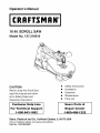
1
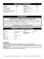
Operator's Manual
CRAFTSMAN°
16 IN. SCROLL SAW
Model No. 137.216010
CAUTION:
Before using this Scroll Saw,
read this manual and follow
all its Safety Rules and
Operating Instructions
Customer
For
Help
Technical
Line
Support
1-800-843-1682
•
•
Safety Instructions
Installation
•
•
Operation
Maintenance
•
Parts List
Sears
Repair
Part No. 137216010001
Center
1-800-488-1222
Sears, Roebuck and Co., Hoffman Estates, IL 60179 USA
Visit our Craftsman website: www.sears.com/craftsman
Parts
&
SECTION
PAGE
Warranty ........................................
Product Specifications .......................
Power Too] Safety .............................
Scroll Saw Safety ..................................
Electrical Requirements and Safety ......
Accessories and Attachments ..............
Carton Contents ....................................
ONE-YEAR
SECTION
PAGE
Know Your Scroll Saw ...........................
Glossary of Terms .............................
Assembly and Adjustments .................
Operation ........................................
Maintenance ...................................
Troubleshooting Guide ........................
Parts List ...........................................
2
2
3
4
5
6
6
FULL WARRANTY
ON CRAFTSMAN
7
8
9
13
16
17
18
TOOL
If this Craftsman tool fails due to a defect in material or workmanship within one year from the date of purchase,
CALL 1-800-4-MY-HOME® TO ARRANGE FOR FREE REPAIR (or replacement if repair proves impossible).
If this tool is used for commercial or rental purposes, this warranty will apply for only ninety days from the date of
purchase. This warranty applies only while this tool is in the United States.
This warranty gives you specific legal rights, and you may also have other rights, which vary, from state to state.
Sears, Roebuck
•
and Co., Hoffman
Estates,
IL 60179
m
MOTOR
TABLE
Power Source ........................
Speed ....................................
Speed Control .........................
BLADE
120V AC, 60HZ, 1.6Amp
400-1600 SPM
Electric
Type .....................................
Depth of Throat .........................
Blade Stroke ............................
Pin-end or Plain-end
16-1/16 in.
11/16 in.
Depth of 45 ° Cut ....................
Depth of 90 ° Cut .......................
2-1/8 in.
Tilt .................................
SAWDUST BLOWER ......
WORK LIGHT ..................
45 ° Left ; Right
Yes
Yes
1-1/16 in. Right ; 3/4 in. Left
IA WARNING
I
To avoid electrical hazards, fire hazards or damage to the tool, use
This tool is wired at the factory for 110-120 Volt operation. It must
time delay fuse or circuit breaker. To avoid shock or fire, replace
damaged in any way.
Before using your tool, it is critical that you read and understand
rules could result in serious injury to you or damage to the tool.
proper circuit protection.
be connected to a 110-120 Volt / 15 Ampere
power cord immediately if it is worn, cut or
these safety rules. Failure to follow
these
GENERAL SAFETY INSTRUCTIONS
BEFORE USING THIS POWER TOOL
Safety is a combination of common sense, staying alert
and knowing how to use your power tool.
IA WARNING I
To avoid mistakes that could cause serious injury,
do not plug the tool in until you have read and
understood the following,
1. READ and become familiar with the entire Operator's
Manual. LEARN the tool's application, limitations and
possible hazards.
2. KEEP GUARDS IN PLACE and in working order.
3. REMOVE ADJUSTING KEYS AND WRENCHES.
Form the habit of checking to see that keys and
adjusting wrenches are removed from the tool before
turning ON.
Safety standard Z87.1 Everyday eyeglasses have
only impact-resistance lenses. They ARE NOT safety
glasses. Safety Goggles are available at Sears.
NOTE: Glasses or goggles not in compliance with
ANSI Z87.1 could cause serious injury.
13.WEAR A FACE MASK OR DUST MASK. Sawing
operation produces dust.
14.SECURE WORK. Use clamps or a vise to hold work
when practical. It's safer than using your hand and it
frees both hands to operate tool.
15.DISCONNECT TOOLS before servicing; when
changing accessories such as blades, bits, cutters,
and the like.
16.REDUCE THE RISK OF UNINTENTIONAL
STARTING. Make sure switch is in OFF position
before plugging in.
4. KEEP WORK AREA CLEAN. Cluttered areas and
benches invite accidents.
17.USE RECOMMENDED ACCESSORIES. Consult the
Operator's Manual for recommended accessories.
The use of improper accessories may cause risk of
injury to persons.
5. DON'T USE IN DANGEROUS ENVIRONMENT.
Don't use power tools in damp or wet locations, or
expose them to rain. Keep work area well lighted.
1&NEVER STAND ON TOOL. Serious injury could
occur if the tool is tipped or if the cutting tool is
unintentionally contacted.
6. KEEP CHILDREN AWAY. All visitors should be kept
a safe distance from work area.
19.CHECK FOR DAMAGED PARTS. Before further
use of the tool, a guard or other part that is damaged
should be carefully checked to determine that it will
operate properly and perform its intended function
- check for alignment of moving parts, binding of
moving parts, breakage of parts, mounting, and any
other conditions that may affect its operation. A guard
or other part that is damaged should be properly
repaired or replaced.
7. MAKE WORKSHOP CHILD PROOF with padlocks,
master switches, or by removing starter keys.
8. DON'T FORCE THE TOOL. It will do the job better
and safer at the rate for which it was designed.
9. USE THE RIGHT TOOL. Do not force tool or
attachment to do a job for which it was not designed.
10.USE PROPER EXTENSION CORD. Make sure
your extension cord is in good condition. When
using an extension cord, be sure to use one heavy
enough to carry the current your product will draw.
An undersized cord will result in a drop in line
voltage and in loss of power that will cause the tool
to overheat. The table on page 5 shows the correct
size to use depending on cord length and nameplate
ampere rating. If in doubt, use the next heavier
gauge. The smaller the gauge number, the heavier
the cord.
11 .WEAR PROPER APPAREL. Do not wear loose
clothing, gloves, neckties, rings, bracelets or other
jewelry that may get caught in moving parts. Nonslip footwear is recommended. Wear protective hair
covering to contain long hair.
12.ALWAYS WEAR EYE PROTECTION. Any Scroll
Saw can throw foreign objects into the eyes that
could cause permanent eye damage. ALWAYS wear
Safety Goggles (not glasses) that comply with ANSI
20.NEVER LEAVE TOOL RUNNING UNATTENDED.
TURN POWER "OFF". Don't leave tool until it comes
to a complete stop.
21 .DON'T OVERREACH.
balance at all times.
Keep proper footing and
22.MAINTAIN TOOLS WITH CARE. Keep tools sharp
and clean for best and safest performance. Follow
instructions for lubricating and changing accessories.
23.DIRECTION OF FEED. Feed work into a blade or
cutter against the direction of rotation of the blade or
cutter only.
24.DO NOT OPERATE the tool if you are under the
influence of any drugs, alcohol or medication that
could affect your ability to use the tool properly.
25.DUST generated from certain materials can be
hazardous to your health. Always operate the saw
in well-ventilated area and provide for proper dust
removal. Use dust collection systems whenever
possible.
SPECIFIC SAFETY INSTRUCTIONS
THIS SCROLL SAW
FOR
13.HOLD WORKPIECE
FIRMLY against the table top.
14.NEVER CUT MATERIAL that is too small to be held
1. READ AND UNDERSTAND all safety instructions
and operating procedures throughout the manual.
safely.
15.DO NOT USE dull or bent blades.
2. DO NOT OPERATE the Scroll Saw until it is
completely assembled and installed according to the
instructions.
3. SHOULD any part of Scroll Saw be missing,
damaged, or fail in any way, or any electrical
component fail to perform properly, shut off the switch
and remove the plug from the power supply outlet.
Replace missing, damaged, or failed parts before
resuming operation.
4. IF YOU ARE NOT thoroughly familiar with the
operation of a Scroll Saw, obtain advice from your
supervisor, instructor or other qualified person.
5. SERIOUS INJURY could occur if the tool tips over
or you accidentally hit the cutting tool. Do not store
anything above or near the tool.
16.TURN THE SAW OFF AND UNPLUG THE CORD
if the blade binds in the saw kerf while being backed
out of the workpiece, usually caused by sawdust
clogging the kerf. If this happens, turn off the scroll
saw and unplug the power cord. Wedge open the
kerf and back the blade out of the workpiece.
17.DO NOT feed the material too fast while cutting. Only
feed the workpiece at the rate the saw will cut.
18.TURN THE POWER OFF, remove the switch key
and make sure the scroll saw comes to a complete
stop before installing or removing an accessory, and
before leaving the work area.
19.DO NOT START the saw with workpiece pressing
against the blade. Slowly feed the workpiece into the
moving blade.
6. AVOID INJURY from unexpected saw movement.
Place the saw on a firm level surface where the
saw does not rock and bolt or clamp the saw to its
support.
20.WHEN CUTTING a large workpiece, MAKE SURE
the material is supported at table height.
7. YOUR SCROLL SAW MUST BE SECURELY
21 .EXERCISE CAUTION when cutting workpieces that
are round or irregularly shaped, workpieces can
pinch the blade.
FASTENED to a stand or workbench. If there is any
tendency for the stand or workbench to move during
operation, the stand or workbench MUST be fastened
to the floor.
22.ALWAYS release blade tension before loosening the
blade holder screw.
8. THIS SCROLL SAW is intended for indoor use only.
23.MAKE CERTAIN table tilting lock is tightened before
starting the machine.
9. TENSION BLADE PROPERLY before starting the
saw. Recheck and adjust tension as needed.
24.NEVER REACH under the scroll saw table when
motor is running.
10.BLADE TEETH MUST POINT downward toward the
table.
11 .TABLE MUST BE CLEARED of all debris before
operating saw. Do not perform lay out, set up or
assemble work on the table when the saw is in
operation.
12.TO PREVENT INJURIES, avoid awkward hand or
finger positions, where a sudden slip could cause a
hand to move into the blade when operating the saw.
25.CHECK FOR DAMAGED
PARTS before each use.
Check for alignment of moving parts, binding of
moving parts, breakage of parts, mounting or any
other conditions that may affect operation. Parts that
are damaged should be properly repaired or replaced
before using the tool.
26.THINK SAFETY.
GROUNDING
INSTRUCTIONS
IN THE EVENT OF A MALFUNCTION OR
BREAKDOWN, grounding provides a path of least
resistance for electric currents and reduces the risk of
electric shock. This tool is equipped with an electrical
cord that has an equipment-grounding conductor
and a grounding plug. The plug must be plugged
into a matching receptacle that is properly installed
and grounded in accordance with all local codes and
ordinances.
DO NOT MODIFY THE PLUG PROVIDED. If it will not
fit the receptacle, have the proper receptacle installed
by a qualified electrician.
IMPROPER CONNECTION of the equipment grounding
conductor can result in risk of electric shock. The
conductor with the green insulation (with or without
yellow stripes) is the equipment grounding conductor.
If repair or replacement of the electrical cord or plug is
necessary, do not connect the equipment grounding
conductor to a live terminal.
CHECK with a qualified electrician or service person
if you do not completely understand the grounding
instructions, or if you are not certain the tool is properly
grounded.
lag fuse or a #14 wire with a 15 A time-lag fuse. Before
connecting the motor to the power line, make sure the
switch is in the off position and the electric current is
rated the same as the current stamped on the motor
nameplate. Running at a lower voltage will damage the
motor. This tool is intended for use on a circuit that has
a receptacle like the one illustrated in Fig. 1.
Fig. 1 shows a three-pronged electrical plug and
receptacle that has a grounding conductor. If a properly
grounded receptacle is not available, an adapter (Fig. 2)
can be used to temporarily connect this plug to a twocontact grounded receptacle. The adapter (Fig. 2) has a
rigid lug extending from it that MUST be connected to a
permanent earth ground, such as a properly grounded
receptacle box.
la, WARNING
I
In all cases, make certain the receptacle is properly
grounded. If you are not sure, have a qualified
electrician check the receptacle.
la, WARNING
I
This tool is for indoor use only. Do not expose to
rain or use in damp locations.
Fig. 1
Three-Pronged
USE only three-wire extension cords that have threepronged grounding plugs with three-pole receptacles
that accept the tool's plug. Repair or replace damaged
or worn cords immediately.
GUIDELINES
FOR EXTENSION
CORDS
USE THE PROPER EXTENSION CORD. Make sure
your extension cord is in good condition. Use an
extension cord heavy enough to carry the current your
product will draw. An undersized cord will cause a drop
in line voltage resulting in loss of power, overheating
and burning out of the motor. The table on the right
shows the correct size to use depending on cord length
and nameplate ampere rating. If in doubt, use the next
heavier gauge. The smaller the gauge number, the
heavier the cord.
Make sure your extension cord is properly wired and in
good condition. Always replace a damaged extension
cord or have it repaired by a qualified technician before
using it. Protect your extension cords from sharp
objects, excessive heat and damp or wet areas.
Use a separate electrical circuit for your tool. This
circuit must not be less than #12 wire with a 20 A time-
Plug
_gProng
Properly Grounded
Three-Pronged Receptacle
Fig. 2
Grounding Lug
Make sure this is
connected to a
known ground.
ed
Receptacle
Adapter
14WARNING
I
This tool must be grounded while in use to protect
the operator from electric shock.
+LV_II_IILV_iiJ_V_[_;'ti[_
_iI_o] ;t I=K4iil=l_.[-..!
[o]_.1
[o,.[o]
r,1B[-,.![_]
(When using 120 volts only)
Ampere Rating
Total length of Cord
MoreThan
Not MoreThan 25ft. 50ft. 100ft. 150ft.
'6
6
10
12
10
12
16
8
6
14
16
16
12
14
14
12
12
Not Recommended
AVAILABLE
[_
•
ACCESSORIES
UNPACKING
WARNING I
CONTENTS
I A. WARNING I
To avoid injury, do not attempt to modify this tool
or create accessories not recommended for use
with this tool. Any such alteration or modification
is misuse and could result in a hazardous
condition leading to possible serious injury.
•
AND CHECKING
Use only accessories recommended for this
scroll saw. Follow instructions that accompany
accessories. Use of improper accessories may
cause hazards.
•
To avoid injury, if any part is missing or
damaged, do not plug the scroll saw in until
the missing or damaged part is replaced, and
assembly is complete. Call 1-800-4-MY-HOME ®
for replacement parts.
• To avoid fire and toxic reaction, never use
gasoline, naphtha, acetone, lacquer, thinner or
similar highly volatile solvents to clean the scroll
saw.
Visit your Sears Hardware Department or see the
Carefully unpack the scroll saw and all its parts and
Sears Power and Hand Tool Catalog for the following
accessories:
compare against the illustration following.
1. Remove the scroll saw from the carton by lifting the
saw by the back of the upper frame.
2. Place the saw on a secure surface and examine it
ITEM
Pin-end saw blades
carefully.
Plain-end saw blades
Sears may recommend other accessories not listed in
this manual.
CAUTION: Do not lift this saw by the arm that holds the
blade, this may result in damage to the tool.
See your nearest Sears store or Power and Hand Tool
Catalog for other accessories.
Do not use any accessory unless you have completely
read the instruction or Operator's Manual for that
accessory.
ill[.I.]K-"l
_I_ :I .] _ .]I =[._"[-']
_ _vJ
:] ai'/"
Supplied
Scroll saw
Hex key 3 mm
Blade
Hex key
Quickrelease
tensionlever
Variablespeed
controlknob
Bladeguard
footlockknob
light
Bladestorage
Sawdustblower
Upperarm
Bladeguardfoot
Bevelscale
Mountingholes
ON/OFFswitch
Worktable
Blade
lockknob
Tablelockknob
Sawdustcollectionport
SCROLL
SAW TERMS
WOODWORKING
BEVEL SCALE - Represents the degree of table angle
from 0 ° to 45 ° when the table is tilted for bevel cutting.
BLADE GUARD FOOT - Guards the blade and keeps
your workpiece from rising. Helps protect fingers from
blade contact.
TERMS
BLADE TOOTH SET - The total width the blade will
cut based on the distance from the outside point of one
bent tooth to the outside point of the next bent tooth
establishing set of teeth.
BLADE GUARD FOOT LOCK KNOB - Allows you to
raise or lower the foot and lock it at the desired height.
DEFLECTION - Slight movement of blade in the
horizontal direction while the blade is moving inline
during cutting operation. This may be caused by the
blade following the grain or the path of least resistance.
BLADE HOLDERS - Retain and position the blades.
FEED - Rate of moving material to be cut into the blade.
BLADE STORAGE - Provides convenient easy access
to extra blades or wrenches.
KERF - The slot cut by the blade.
QUICK RELEASE TENSION LEVER - Quickly loosens
is guided into the blade.
and retightens the blade to its original tension. The
tension lever quickly sets and resets the blade tension
SAW BLADE PATH - Area or line of sight of the
LEADING EDGE - The front edge of the workpiece that
when performing interior cutting operations or changing
blades.
workpiece moving in line toward the saw blade edge.
SURFACE - Top of workpiece being cut.
SAWDUST BLOWER - Keeps sawdust from covering
the line of sight for more accurate cuts. The best results
occur when the blower tube is directed toward the blade
TRAILING EDGE - The end of the workpiece edge last
cut by the saw blade.
and workpiece.
SAWDUST COLLECTION
PORT - Allows vacuum hose
WORKPIECE - Material on which the cutting operation
is being performed.
or attachments to be used to remove the sawdust from
under the table and base.
TABLE LOCK KNOB - Securely locks the table at the
angle desired for bevel cutting.
Leading edge
Saw blade path
Kerf
Surface
VARIABLE
SPEED ON/OFF CONTROL KNOB -
Variable switch dial allows greater versatility when
cutting a variety of materials. Adjust the speed to the
desired setting, between 400 to 1600 strokes per minute
(SPM), by turning the control knob clockwise or counter
clockwise.
Trailing edge
Workpiece
ASSEMBLY
INSTRUCTIONS
IA WARNING I
To avoid injury, do not connect this scroll saw to the
power source until it is completely assembled and
adjusted and you have read and understood this
instruction manual.
MOUNTING SCROLL SAW TO WORK SURFACE
(FIG. A)
1. If mounting the scroll saw to a workbench, a solid
SAWDUST COLLECTION PORT (FIG. C)
This scroll saw will accept a hose or vacuum accessory
(not provided) to be connected to the port (1) on the
right side of base. If excessive sawdust buildup occurs
inside the base, use a wet/dry vacuum cleaner or
manually remove sawdust by removing the screws
on the right side of saw. Reattach the metal plate and
screws before starting the saw. This will keep your saw
cutting efficiently.
Fig. C
wood bench is preferred over a plywood board to
reduce noise and vibration.
2. The hardware to mount this saw is NOT supplied with
the saw. The hardware as shown in Fig. A should be
used:
Fig, A
1
2
1
3
II
ii
BLADE REMOVAL AND INSTALLATION
4
6
1. (3) Hex head bolts; length as required
2.
3.
4.
5.
(6) Flat washers
Foam pad or carpet (optional)
(3) Lock washers
(3) Hex nuts
6. (3) Jam nuts
BLADE STORAGE (FIG, B)
The blade storage (1) is located on the left rear side of
the scroll saw body. Pull out the blade storage (1) to
open. The blade storage can conveniently store your
hex wrenches and both Pin-end and Plain-end blades.
Fig. B
PLAIN-END BLADE REMOVAL AND INSTALLATION
This scroll saw accepts 5-inch plain-end or pin-end
blades to cut a wide variety of materials.
Plain-end type blades are recommended whenever
fine, accurate and intricate work is- being performed on
3/4 in. or thinner material. It will take slightly longer to
assemble the blade and blade tension, but you will also
be able to use finer blades for cutting a thinner kerf.
I A WARNING I
To avoid injury from accidental starting, always
turn the switch OFF and remove power cord plug
from power source before removing or replacing the
blade.
PLAIN-END BLADE REMOVAL (FIG. D, E, F)
PLAIN-END BLADE INSTALLATION
(FIG. F, G, H)
1. To remove the blade, loosen the blade tension by
lifting the quick release tension lever. (2-Fig. D)
CAUTION: In order to avoid uncontrollable lifting of the
workpiece, the teeth of the blade should ALWAYS point
downward.
Fig. D
NOTE: The tension of a scroll saw blade must be very
tight.
1. Install the new blade through the access hole in the
table with teeth pointing down.
2. Insert the new blade into the lower blade holder slot
(13), then tighten the lower blade holder knob (9).
(Fig. G)
2. Loosen the upper blade holder (4) by turning the
blade holder lock knob (5) counterclockwise. (Fig. E)
NOTE: The hex set screw (6) on the left side is used
for fine adjustments and is only adjusted if the blade
is not perpendicular to the table.
Fig. E
_
_12
13
3. Tilt the table to the 0 ° bevel setting and lock the bevel
knob.
4. Insert the other end of the blade into the upper blade
holder slot (12-Fig. G) and then tighten the quick
release knob (1-Fig. H).
NOTE: Apply slight downward pressure against the
upper arm (3-Fig. G) when installing the blade into
the upper blade holder.
3. Tilt the table to 0 ° and tighten the table lock knob
(7-Fig. F). Loosen the lower blade holder lock knob
(9-Fig. E) under the table on the left side of the lower
blade holder (8-Fig. E) by turning counterclockwise.
5. Tighten the tension on the blade by turning the
tension knob (2-Fig. H) clockwise. Check the tension
on the blade. If too loose, turn lever clockwise. Do
4. Remove the blade from the upper and lower blade
holders by pulling forward and lifting the blade
through the access hole (10) in the table (11 ). (Fig. F)
not make too tight or blade will easily break in use.
(Fig. H)
NOTE: The quick release lever must always be down
to make the tension adjustments, Release the quick
Fig. F
release lever upward only during blade changing
operations. If the blade is over-tightened,the lever is
difficult to lower.
Fig. H
1
10
PIN-END BLADE REMOVAL AND INSTALLATION
I_
PIN-END BLADE INSTALLATION
( FIG. K, L )
NOTE: Do not tighten the lock knobs (8-Fig.K) when
using Pin-end blades.
CAUTION: In order to avoid uncontrollable lifting of the
workpiece, the teeth of the blade should always point
downward.
WARNING I
To prevent personal injury, always turn the saw
OFF and disconnect the plug from source before
changing blades or making adjustments,
1. Install the blade (1) by inserting one end of it through
the access hole (6) or throat plate in the table. Hook
Pin-end type blades are thicker for stability and for faster
assembly. These blades are used whenever faster
cutting on a variety of materials and 3/4 in. thickness or
the lower blade pin in the pin recess in the lower
blade holder (5) and then the upper blade pin in the
upper blade holder (4). (Fig. K)
greater are required. Use whenever less precision or
thicker kerf cutting is acceptable.
NOTE: When installing pin-end blades, the set screws
located on the upper and lower blade holders should
not be over or under tightened. The slot must be slightly
wider than the thickness of the blade. After the blade is
Fig, K
_4
installed, the blade tension mechanism will keep the
pin-end in place.
PIN-END BLADE REMOVAL (FIG. I, J)
1. To remove the blade, loosen the tension by lifting up
the quick release tension lever. (2-Fig. 1)
Fig, I
2
Check to see that the pins are properly located in the
upper (4) and the lower (5) blade holders.
3. To tension the blade (1 -Fig.K), lower the quick
2.
release tension lever (2). Check the tension on
the blade; if tension is too tight, turn the knob (3)
counterclockwise. If tension is too loose, turn the
knob (3) clockwise. (Fig. L)
NOTE: If the blade is over tensioned, the lever will be
difficult to lower and could result in damage to the
2. Remove the blade (1) from the upper (4) and lower (5)
blade holder by pulling forward to release, and lift the
blade through the access hole. (Fig. J)
blade holder or arm assembly.
Fig. L
Fig, J
3. Tilt the table to a 45 ° angle and lock the bevel lock
knob to view lower blade holder (8). (Fig. J)
NOTE: Apply slight downward pressure on the upper
arm when removing the blade from the upper blade
holder.
11
BLADE GUARD FOOT ADJUSTMENT
(FIG. M, N)
BLADE SELECTION (FIG. P)
14WARNING
I
NOTE: User must keep constant downward pressure
on workpiece when cutting. The blade guard foot is not
designed to hold down the workpiece, but rather a guard
to help prevent the workpiece from lifting up excessively.
To avoid injury from accidental starting, always turn
the switch OFF and unplug the scroll saw before
moving, replacing
the blade or making adjustments.
When cutting at angles, the table guard foot (1) should
This scroll saw accepts 5-inch length blades with a
be adjusted so it's parallel to the table and rests flat
above the workpiece.
1. To adjust, loosen the screw (2), tilt the foot so it's
wide variety of blade thickness and widths. The type
of material and intricacies of cutting operations (size of
radius or curve) will determine the number of teeth per
inch. As a general rule, always select the narrowest
parallel to table and tighten the screw.
2. Loosen the blade guard foot lock knob (3) to raise
or lower the foot until it rests slightly above the
workpiece. Tighten blade guard foot lock knob.
blades for intricate curve cutting and the widest blades
for straight and large curve cutting operations.
The following table represents suggestions for various
materials. When purchasing blades, refer to the back of
the package for the best use of blades and speeds on
various materials.
NOTE: To remove the blade guard foot (1), loosen the
hex screw (2) and by using a hex. key to turn the screw
counterclockwise. (Fig. N)
Use this table as an example, but practice and your own
Fig. M
personal preference will be the best selection method.
Fig. P
9.5-15
TEETH/
INCH
TPI
Fig. N
2
15-28
BLADE
WIDTH
INCH
BLADE
THICKNESS
INCH
BLADE/
SPM
9.5-15
0.110
0.018
400-1200
15-28
.055-.110
.010-.018
800-1800
30-48
.024-.041
.012-.019
Varies
1
SAWDUST BLOWER (FIG. O)
The sawdust blower (1) should be positioned to point to
the blade and workpiece to blow sawdust out of the lineof sight when cutting. It is not designed to blow all of the
sawdust off the table.
30-48
MATERIAL
CUT
Medium turns on
1/4 in. to 1-3/4 in.
wood, soft metal,
hardwood
Small turns on 1/8
in. to 1-1/2 in. wood,
soft metal, hardwood
Non-ferrous
metals/hardwoods
using very slow
speeds
NOTE: When using blades, sometimes speeds must
change to compensate for smaller curves, radii or
smaller diameters. Thinner blades will have more
Fig. O
possibilities for blade deflection when cutting angles
which are not perpendicular to the table. Read BASIC
SCROLL SAW OPERATION for more suggestions.
NOTE: The blade must be installed with the teeth
pointing downward, as shown in Fig. P, to prevent the
workpiece from being pulled upward by the saw blade
action.
12
VARIABLESPEEDCONTROL
ON/OFFSWITCH
RECOMMENDATIONS
The variable speed control allows greater versatility to
1. When feeding the workpiece into the blade do not
force the leading edge of the workpiece into the blade
because the blade will deflect, reducing the accuracy
cut a variety of materials such as wood, plastics, nonferrous metals, etc. Depending on the hardness and
thickness of material, the speed should be reduced to
allow the blade teeth to remove cut material from the
kerf.
FOR CUTTING
of cut and possibly breaking the blade. Allow the
saw to cut material by guiding the workpiece into the
blade as it cuts.
2. The blade teeth cut material ONLY on the down
stroke.
REPLACING THE BULB
1. Use only a 10 walt maximum bulb. Turn the light
switch off and unplug the saw.
2. Remove old bulb. Place new bulb into socket.
3. You must guide the wood into the blade slowly
ON/OFF SWITCH (FIG. Q)
1. To turn power ON or OFF, push the ON/OFF
switch (2).
4. There is a learning curve for each person who
VARIABLE
because the teeth of the blade are very small and
they can only remove wood when they are on the
down stroke.
wants to use this saw. During that period of time it is
expected that some blades will break until you learn
how to use the saw and receive the greatest benefit
from the blades.
SPEED SWITCH
5. Best results are achieved when cutting wood less
than one inch thick.
1. Your saw is equipped with a variable speed control
knob(1 ). The blade stroke rate may be adjusted by
simply rotating the variable speed control knob (1).
To increase speed, rotate dial clockwise. To reduce
speed, rotate dial counterclockwise.
6. When cutting wood thicker than one inch, the user
must guide the wood very slowly into the blade and
take extra care not to bend or twist the blade while
Fig, Q
cutting in order to maximize blade life.
7. Teeth on scroll saw blades wear out and must be
1
replaced frequently for best cutting results. Scroll
saw blades generally stay sharp for 1/2 to 2 hours of
cutting.
8. To get accurate cuts, be prepared to compensate for
the blade's tendency to follow the wood grain as you
are cutting.
9. This scroll saw is intended to cut wood or wood
products. Precious and non-ferrous perform well on
scroll saws that have very slow speed capability, and
should be lubricated with machine oil or beeswax.
OVERLOAD BREAKER (FIG. Q, R)
When the motor becomes too hot during operation, the
10.When choosing a blade to use with your scroll saw,
consider very fine, narrow blades to scroll cut in
thin wood 1/4 in. thick or less. Use wider blades for
overload breaker switch (3) will cause the motor to stop
automatically to prevent damage to the motor. Push in
on the ON/OFF switch (2) to turn saw OFF and do not
restart until the motor has had time to cool. Push in on
thicker materials but this will reduce the ability to cut
tight curves.
11 .This saw uses 5 in. long pin or plain end type blades.
the breaker switch (3) and switch the ON/OFF switch (2)
to ON to start the saw.
3
FIG. R
12.Blades wear faster when cutting plywood or particle
board which is very abrasive. Angle cutting in
hardwoods reduces blade set faster due to the blade
deflection.
13
FREEHAND CUTTING (FIG. S)
ANGLE CUTTING (FIG. S, T)
IA WARNING I
I,AWARNING
I
To avoid injury from an accidental start, make sure
the switch is in the OFF position and the plug is not
To avoid injury from an accidental starting, make
sure the switch is in the OFF position and the plug
connected to the power source outlet.
is not connected to the power source outlet before
moving, replacing the blade or making adjustments.
1. Lay out desired design, or secure design to the
workpiece (1).
2. Raise the blade guard foot (2) by loosening the blade
1. Lay out or secure design to workpiece (1).
2. Move the blade guard foot (2) to the highest position
by loosening the blade guard foot lock knob (3) and
retighten. (Fig. S)
guard foot lock knob(3).
3. Position the workpiece against the blade and place
the blade guard foot slightly above the top surface of
3. Tilt the table (4) to the desired angle by loosening the
table lock knob (5) and move the table to the proper
the workpiece.
4. Secure the blade guard foot (2) by tightening the
blade guard foot lock knob (3).
5. Remove the workpiece from the blade prior to turning
angle, using the degree scale (6) and the pointer (7).
(Fig. T)
4. Tighten the table lock knob (5).
the scroll saw ON. Pull the variable speed control
knob (4) out and set the desired speed by turning the
control knob clockwise or counterclockwise.
5. Loosen the blade guard screw (8), and tilt the blade
guard to the same angle as the table (4). Retighten
the blade guard screw.
6. Position the workpiece on the left and right side of
CAUTION: In order to avoid uncontrollable lifting of
the workpiece and to reduce blade breakage, do not
turn saw ON while the workpiece is against the
blade.
the blade (9). Lower the blade guard foot slightly
above the surface by loosening the blade guard foot
lock knob (3).
7. Follow items 4-8 under FREEHAND CUTTING
OPERATION.
6. When turning the scroll saw ON, position the
workpiece against scrap wood prior to touching the
leading edge of the workpiece against the blade.
7. Slowly feed the workpiece into the blade by guiding
and pressing the workpiece down against the table.
Fig. T
CAUTION: Do not force the leading edge of the
workpiece into the blade. The blade will deflect,
reducing accuracy of cut, and may break.
8. When the cut is complete, move the trailing edge of
1
3
the workpiece beyond the blade guard foot. Turn the
scroll saw OFF.
9
Fig. S
4
2
/
3
14
4
RIP OR STRAIGHT LINE CUTTING (FIG. U)
9. When the cut is complete, move the trailing edge of
IA WARNING I
the workpiece beyond the blade guard foot. Turn the
scroll saw OFF.
To avoid injury from an accidental starting, make
sure the switch is in the OFF position and the plug
NOTE: When cutting a narrow workpiece use push
sticks.
is not connected to the power source outlet before
moving, replacing the blade or making adjustments.
Fig, U
Tools Needed (Not Included)
QUANTITY
2
1
1
3
DESCRIPTION
1
Small C-clamps
Ruler or measuring tape
2-inch straight scrap of wood
Thickness to match workpiece)
5
1. Raise the blade guard foot (1) by loosening the
blade guard foot lock knob (2) on the right side of the
upper arm. Measure from the tip of the blade (3) to
the desired distance. Position the straight edge (4)
parallel to the blade at that distance.
INTERIOR CUTTING (FIG. V)
2. Clamp the straight edge (4) to the table (5).
3. Recheck your measurements, using the workpiece to
be cut, and make sure the scrap wood is secure.
1. Lay out the design on the workpiece (1). Drill a 1/4 in.
hole in the workpiece.
2. Release the quick release tension lever (2), remove
the blade (3). Refer to BLADE REMOVAL AND
INSTALLATION.
4. Position the workpiece against the blade and place
the blade guard foot (1) slightly above the top surface
of the workpiece.
5. Secure the blade guard foot in place by tightening
3. Place the workpiece on the saw table with the hole (4)
over the access hole in the table (5).
the height adjustment knob.
6. Remove the workpiece from the blade prior to turning
the scroll saw ON. Set the desired speed by turning
the control knob clockwise or counterclockwise.
4. Install the blade (3) through the hole in the workpiece
and lower the quick release tension lever (2).
5. Follow the process, items 3-9, under FREEHAND
CUTTING OPERATIONS.
CAUTION: In order to avoid uncontrollable lifting
of the workpiece and reduce blade breakage, do
6. When finished making the interior scroll cuts simply
turn the scroll saw OFF, remove the blade from the
blade holder and remove the workpiece from the
table.
not turn saw ON while the workpiece is against the
blade.
7. Position the workpiece against the straight edge (4)
prior to touching the leading edge of the workpiece
Fig, V
2
against the blade (3).
8. Slowly feed the workpiece into the blade, guiding the
workpiece against the straight edge and press the
workpiece down against the table while cutting.
CAUTION: Do not force the leading edge of the
workpiece into the blade. The blade will deflect,
reducing accuracy of cut and may break.
3
4
5
15
IA WARNING I
For your own safety, turn the switch OFF and
remove the plug from the power source before
maintaining your saw.
GENERAL
An occasional coat of paste wax on the work table will
allow the wood being cut to glide smoothly across the
work surface.
MOTOR
1. If the power cord is worn, cut or damaged in any way,
have it replaced immediately.
2. Do not attempt to oil the motor bearings or service
the motor internal parts.
IA WARNING I
To avoid injury from accidental starting, always turn switch OFF and unplug the tool before moving,
replacing
the blade or making adjustments.
Consult your Sears Service Center if for any reason the motor will not run.
PROBLEM
Breaking blades
PROBLEM
1.
2.
3.
4.
Motor will not run.
1.
2.
3.
CAUSE
Wrong tension.
Overworking blades.
Wrong blade
application.
Twisting blade in wood.
Defective cord or plug.
Defective motor.
Blown overload breaker.
REMEDY SUGGESTED
1.
2.
3.
4.
Avoid side pressure on blade. See BLADE
REMOVAL AND INSTALLATION section.
1.
Replace defective parts before using saw again.
See ELECTRICAL REQUIREMENTS AND SAFETY
section.
Call Service Center. Any attempt to repair this motor
may create a HAZARD unless the repair is done by
a qualified technician.
Push the motor switch to the OFF position. Let
the motor cool. See OPERATION-OVERLOAD
BREAKER section.
See mounting instructions in this manual for proper
mounting technique.
The heavier your workbench is, the tess vibration
will occur. A plywood workbench will not be as good
a work surface as the same size solid lumber. Use
2.
3.
Excessive
vibration.
NOTE: There wilt always
be some vibration
}resent when the saw is
1.
1.
saw.
2.
running because of motor 3.
operation.
4.
Blade run out.
Blade not in line with arm
motion.
Improper mounting of
1.
Unsuitable mounting
surface.
Loose table or table
resting against motor.
Loose motor mounting.
Adjust blade tension. See BLADE REMOVAL AND
INSTALLATION section.
Reduce feed rate. See BLADE REMOVAL AND
INSTALLATION section.
Use narrow blade. See BLADE SELECTION
section.
2.
3.
4.
Blade holders not aligned. 1.
17
common sense in choosing a mounting surface.
Tighten the table lock knob.
Tighten motor mounting screw.
Loosen blade holder lock knob holding blade holder
to arms. Adjust position of blade holders. Retighten
blade holder lock knob. See BLADE REMOVAL
AND INSTALLATION section.
16 IN. SCROLL
SAW
MODEL
NO. 137.216010
IA WARNING I
When servicing use only CRAFTSMAN
replacement
parts. Use of any other parts many create a HAZARD
or cause product damage. Any attempt to repair or replace electrical parts on this Scroll Saw may create a
HAZARD unless repair is done by a qualified service technician. Repair service is available st your nearest
Sears Service Center.
PARTS LIST FOR SCROLL SAW SCHEMATIC
I. D, NO
Description
0751
PLUNGER
0752
TENSION
0404
STICKER
075B
INSERT
075E
CAUTION
LABEL
075L
PLUNGER
HOUSING
075N
HANDLE
076B
VARIABLE
OBJA
SPRING
0A98
COMPRESSION
OAM3
Qty
Size
I. D. NO
Description
OKKJ
CR.RE.
OKQW
LOCK
OKQX
NUT
OKQY
LOCK
OKTH
STRAIN RELIEF
OKUX
TERMINAL
OL71
POWER
OLS9
ROCKER
SWITCH
OLSR
CIRCUIT
BREAKER
OLYN
STEEL BALL
WASHER
OU7V
CR. RE. TRUSS HD. TAPPING
OAMW
SET PLATE
OZW4
MOTOR
0C10
BLADE
OZW6
BASE
0C12
BLADE
OZW7
WING
OC 15
BEARING
OZW8
LEVELING
PAD
OCDD
FOOT
OZWG
BEARING
SEAT ASB'Y
ODDW
UPPER ARM
ROCKER
OZWJ
BUSH
ODFi
CONTROLLER
ASS'Y
OZWL
HOUSING
ODF6
BELLOWS
OZWM
BLADE
ODF8
PLUG
OZWN
SUPPORT
ODG2
PVC
OZWP
PLATE COVER
ODG4
AIR DUCT
OZWR
HOLDER
OFPN
EXTENSBION
OZWS
LINGAGE
OGTU
DUST SHIELD
OZWX
BOTTOM
OGXP
CLAMP-CORD
OZXI
CONNECTOR
BOX
OGXQ
PLUNGER
OZX3
CONNECTOR
BOX COVER
OGXR
SHAFT-PIVOT
OZX4
SWITCH
OJ3M
HEX. WRENCH
OZX6
PUSH BUTTON
OJ4U
FLAT WASHER
_6 _ 18-J ,5
10QX
ECCENTRIC
0J66
FLAT WASHER
@4 10-1
1276
SWITCH
BOX COVER
0J91
SPRING
_4
20PI
CLAMP
PLATE
OJAE
EXTERNAL
_4
20XY
HEX.SQCKET
OJAZ
WAVE
WASHER
22KK
GUIDE
OJB0
WAVE
WASHER
27Y7
LEAD WIRE ASS'Y
OJPG
HEX. HD. BOLT
2E73
TABLE
OJU4
HEX, SOC.
HD. CAP
BOLT
M4_0.7-TO
2E78
BRACKET-TILT
OJUZ
HEX. SOC.
HD. CAP
BOLT
MB_J .25-40
2E79
TRUNNION
OJVD
HEX, SOC.
HD. CAP
BOLT
M5XO.8-35
2EBB
CR. RE.COUNT
OJX7
HEX. SOC.
SET SCREW
M6_i
.0-6
2EC3
PLATE COVER
OJX8
HEX. SOC.
SET SCREW
M6_T .0-8
2EC4
GUIDE
OJXR
HEX. SOC.
SET SCREW
MB_1.25-8
2EC5
COVER
0K23
HEX SOC.
HD. CAP
SCREW
M6X1.0-16
2EC7
GUIDE
OK2B
HEX SOC.
HD. CAP
SCREW
M6_1.0-16
2ECA
LAMP
0K56
CR, RE. COUNT
HD. SCREW
M5_0.8-12
2ECB
WIRE ROPE ASS'Y
OK70
CR,-RE.
TRUSS HD, SCREW
M4_0.7-16
2ECC
HOUSING
OK71
CR.-RE.
TRUSS HD. SCREW
M5_0.8-8
2EDG
TILTING SCALE
OK7F
CR. RE. ROUND
M5_0.8-8
2ERU
INSTRUCTION
OKA9
CR.RE.
PAN HD. TAPPING
SCREW
M3_24-10
2EZD
LABEL
OKBD
CR.RE.
PAN HD. TAPPING
SCREW
M4X18-25
2EZH
WARNING
OKBE
CR.RE.
PAN HD. TAPPING
SCREW
M5_I 6-35
2EZJ
TRADE-MARK
OKD7
CR, RE. PAN HD, SCREW
M4_0.7-10
2EZU
TILTING SCALE
OKDK
CR, RE. PAN HD, SCREW
M5_0.8-16
2EZV
WARNING
OKDM
CR, RE. PAN HD, SCREW
M5_0.8-20
2EZW
CAUTION
OKDR
CR. RE. PAN HD. SCREW
M5_0.8-10
2F35
RETAINING
OKEE
CR. RE. PAN HD. SCREW
M5_0,8-50
HANDLE
HANDLE
SPEED CONTROL
KNOB
SPRING
SEAT
ASS'Y
#06
HOUSING
HOSE
ASB'Y
SPRING
HOUSING
WASHER
TOOTH
LOCK
WASHER
M6_i
WASHER
HD. SCREW
.0-30
Qty
Size
PAN HD, ROUND
NECK
SCREW
NUT
M4
0,7-12
M5_0.B
T=5
M6 _ 1,0 T=6
NUT
MB_1.25
CABLE
SWITCH
_10
SCREW
M4
16-16
#AW
NUT
#AW
BOX
ROD
BLADE
ASS'Y
BAR ASB'Y
ARM
ROCKER
#06
BOX
ASSAY
HD.CAP
SCREWS
M6 _1.0-20
CLAMP
#AW
BRACKET
HD. TAPPING
SCREW
M5"12-16
HOLDER
BLOCK
ASS'Y
RIGHT
MANUAL
LABEL
LABEL
LABEL
LABEL
CLIP
#AW
T=8
0"1
Z
0KTH
0LSR
0KBD4
if}
0
ODG4_
0ZX3
0KA9
_076B
OKTO
_/
ozx6
0
r-
r-
OKUX
OJU4ad
OJ91z/!
OAMW 2
OZWM
OKDM
075L
20P1
OZW6
OCDD 3
2EZD
0
0
m
r-
Z
0
OZW8
/
OJPG 5
K_
0
0
Your Home
For repair - in your home - of all major brand appliances,
lawn and garden equipment, or heating and cooling systems,
no matter who made it, no matter who sold it!
For the replacement parts, accessories and
owner's manuals that you need to do-it-yourself.
For Sears professional
installation
of home appliances
and items like garage door openers and water heaters.
1-800-4-MY-HOME
Call anytime,
®
(1-800-469-4663)
day or night (U.S.A. and Canada)
www.sears.oom
www.sears.oa
Our Home
For repair of carry-in items like vacuums, lawn equipment,
and electronics, call or go on-line for the location of your nearest
Sears Parts & Repair Center.
1-800-488-1222
Call anytime,
day or night (U.S.A. only)
www.sears.com
To purchase a protection
or maintenance
agreement
1-800-827-6655
Para pedir servicio
a domicilio,
agreement
(Canada) on a product serviced by Sears:
(U.S.A.)
1-800-361-6665
de reparaci6n
y para ordenar
1-888-SU-HOGAR
® Marca
MO
Marque
Trademark
Registrada
/
TM
Trademark
/ TMMarca
de commerce
/
MD
Marque
M
/ s Service
de F4brica
/ sM Marca
1-800-LE-FOYER
piezas:
_
depos_e
de Sears
Brands,
M°
(1-800-533-6937)
www.sears.ca
Mark of Sears Brands,
de Servicio
(Canada)
Au Canada pour service en frangais:
(1-888-784-6427)
® Registered
(U.S.A.)
de Sears
LLC
LLC
Brands,
LLC
© Sears Brands, LLC