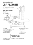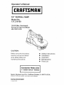
1
Operator's Manual
®
16" SCROLL SAW
Model No.
137.216100
1/9 HP (Max. Developed)
Pin-end or Plain-end Blade
400-1600
S.P.M.
CAUTION"
Before using this Scroll Saw,
read this manual and follow
all its Safety
Operating
•
•
Safety Instructions
Installation
•
•
Operation
Maintenance
Parts List
Rules and
Instructions
Customer
Help Line
1-800-843-1682
Sears,
Roebuck
Visit our Craftsman
10_A20GR
and Co., Hoffman
website:
Estates,
www.sears.corn/craftsman
IL 60179
U.S.A.
SE(_TION
PAGE
Product Specifications ..............................................................................................................................................
Warning .......................................................................................................................................................................
Safety Instructions .....................................................................................................................................................
Accessories and Attachments ..................................................................................................................................
Carton Contents ........... _.............................................................................................................................................
Know Your Scroll Saw ..............................................................................................................................................
2
2
3
6
6
7
Glossary of Terms ......................................................................................................................................................
Assembly and Adjustments ......................................................................................................................................
Basic Saw Operation .................................................................................................................................................
Maintenance ...............................................................................................................................................................
Troubleshooting guide ..............................................................................................................................................
Parts ............................................................................................................................................................................
8
9
13
16
17
18
FULL ONE YEAR WARRANTY
If this Scroll Saw fails due to a defect in material or workmanship within one year of date of purchase,
Sears will at its option repair or replace it free of charge.
Return this Scroll Saw to a Sears Service Center for repair, or to place of purchase
This warranty
to state.
gives you specific
Sears,
Roebuck
for replacement.
legal rights, and you may also have other rights that may vary from state
and Co., Dept. 817 WA, Hoffman
Estates,
IL 60179
Some dust created by power sanding, sawing, grinding, drilling and other construction activities contains chemicals
known to the state of California, to cause cancer, birth defects or other reproductive harm. Some examples of these
chemicals are:
,, Lead from lead-based paints
•
Crystalline silica from bdcks, cement and other masonry products
•
Arsenic and chromium from chemically treated lumber
Your risk from these exposures varies, depending on how often you do this type of work. To reduce your exposure to
these chemicals, work in a well-ventilated area and work with approved safety equipment such as dust masks that are
specially designed to filter out microscopic particles.
Motor
Power source .........
Speed ......................
Speed control ..........
Blade
Type .....................
Depth of Throat .......
Blade Stroke ..........
Depth of 45°Cut ....
Depth of 90°Cut ....
Table
Size ......................
Tilt ........................
SAWDUST BLOWER ......
120 V, 60 Hz, 1.4Amp., Ac
400 ~ 1600 spm
Electronic
Pin-end or Plain-end
16-1/16"
7/8"
1-118" Right; 314"Left
2-1/4 °
12-3/16" X 18-7/8"
45°Left ; Right
Yes
To avoid electrical hazards, fire hazards, or damage to
the tool, use proper circuit protection. Use a separate
electi'ical circuit for your tools.
This Scroll Saw is wired at the factory for 120V operation.
Connect to a 120V, 15 AMP branch circuit and use a !5
Amp time delay fuse or circuit breaker. To avoid shock or
fire, replace power cord immediately if it is worn, cut or
damaged in any way.
GENERAL
BEFORE
SAFETY
INSTRUCTIONS
USING THE SCROLL
SAW
Safety is a combination of common sense, staying alert
and knowing how to use this Scroll Saw.
To avoid mistakes that could cause serious injury, do not
plug the Scroll Saw in until you have read and
understood the following:
1. READ and become familiar with the entire Operator's
Manual. LEARN the tool's application, limitations and
possible hazards.
2. KEEP GUARDS IN PLACE and in working order.
3. REMOVE ADJUSTING KEYS AND WRENCHES.
Form the habit of checking to see that keys and
adjusting wrenches are removed from the tool before
turning ON,
4. KEEP WORK AREA CLEAN. Cluttered areas and
benches invite accidents,
5. DON'T USE IN DANGEROUS ENVIRONMENT.
Don't use power tools in damp or wet locations, or
expose them to rain. Keep work area well lighted.
6. KEEP CHILDREN AWAY, All visitors should be kept a
safe distance from work area,
7. MAKE WORKSHOP CHILD PROOF with padlocks,
master switches, or by removing starter keys.
8. DON'T FORCE THE TOOL. It will do the job better
and safer at the rate for which it was designed.
9. USE THE RIGHT TOOL. Do not force tool or
attachment to do a job for which it was not designed.
10.USE PROPER EXTENSION CORD. Make sure your
extension cord is in good condition. When using an
extension cord, be sure to use one heavy enough to
carry the current your product will draw. An
undersized cord will result in a drop in line voltage
and in loss of power that wilt cause the tool to
overheat. The table on page 5 shows the correct size
to use depending on cord length and nameplate
ampere rating, If in doubt, use the next heavier gauge.
The smaller the gauge number, the heavier the cord.
11.WEAR PROPER APPAREL. Do not wear loose
clothing, gloves, neckties, rings, bracelets, or other
jewelry that may get caught in moving parts. Non-slip
footwear is recommended. Wear protective hair
covering to contain long hair.
12.ALWAYS WEAR EYE PROTECTION. Any Scroll Saw
can throw foreign objects into the eyes that could
cause permanent eye damage. ALWAYS wear Safety
Goggles (not glasses) that comply _th ANSi Safety
standard Z87.1 Everyday eyeglasses have only
impact-resistance lenses. They ARE NOT safety
glasses. Safety Goggles are available at Sears.
NOTE: Glasses or goggles not in compliance with
ANSi Z87.1 could cause serious injury.
13.WEAR A FACE MASK OR DUST MASK. Sawing
operation produces dust.
14.SECURE WORK. Use clamps or a vise to hold work
when practical. It's safer than using your hand and it
frees both hands to operate tool.
15,DISCONNECT TOOLS before servicing; when
changing accessories such as blades, bits,•cutters,
and the like.
16.REDUCE THE RISK OF UNINTENTIONAL
STARTING. Make sure switch is in OFF position
before plugging in.
17.USE RECOMMENDED ACCESSORIES. Consult the
Operator's Manual for recommended accessories.
The use of improper accessories may cause risk of
injury to persons.
18.NEVER STAND ON TOOL. Serious injury could
occur if the tool is tipped or if the cutting tool is
unintentionally contacted.
19.CHECK FOR DAMAGED PARTS. Before further use
of the tool, a guard or other part that is damaged
should be carefully checked to determine that it will
operate properly and perform its intended function check for alignment of moving parts, binding of
moving pads, breakage of parts, mounting, and any
other conditions that may affect its operation. A guard
or other part that is damaged should be properly
repaired or replaced.
20.NEVER LEAVE TOOL RUNNING UNATTENDED.
TURN POWER "OFF". Don't leave tool until it comes
to a complete stop,
21 .DON'T OVERREACH. Keep proper tooting and
balance at al! times.
22,MAINTAIN TOOLS WITH CARE. Keep tools sharp
and clean for best and safest performance. Follow
instructions for lubricating and changing accessories.
23.DIRECTION OF FEED. Feed work into a blade or
cutter against the direction of rotation of the blade or
cutter only.
influence
ofanydrugs,alcoholor medication
that
couldaffectyourabilitytousethetoo!properly.
25.DUST
generated
fromcertainmaterialscanbe
hazardous
toyourhealth.Alwaysoperatethesawin
well-ventilated
areaandprovideforproperdust
remc'.'c',.
Usedustcollection
systemswhenever
possible.
finger positions, where a sudden slip could cause a
hand to move into the blade when operating the saw.
13.HOLD WORKPIECE FIRMLY against the table top.
14.NEVER CUT MATERIAL that is too small to be held
safely.
15.DO NOT USE dull or bent blades.
SPECIFIC SAFETY INSTRUCTIONS
SCROLL SAWS
FOR
READ AND UNDERSTAND all safety instructions
and operating procedures throughout the manual.
2,
DO NOT OPERATE the Scroll Saw until it is
completely assembled and installed according to the
instructions.
3. SHOULD any part of Scroll Saw be missing,
damaged, or fail in any way, or any electrica!
component fail to perform properly, shut off the switch
and remove theplug from the power supply outlet.
Replace missing, damaged, or failed parts before
resuming operation.
16.TURN THE SAW OFF AND UNPLUG THE CORD if
the blade binds in the saw kerf while being backed.
out of the workpiece, usually caused by sawdust
clogging the kerf. If this happens, turn off the scroll
saw and unplug the power cord. Wedge open the kerf
and b__ '_e blade out of "-=_workpiece,
17.DO NOT feed the material too fast while cutting. Only
feed the workpiece at the rate the saw will cut.
18.TURN THE POWER OFF, remove the switch key and
make sure the scroll saw comes to a complete stop
before installing or removing an accessory, and
before leaving the work area.
19.DO NOT START the saw with workpiece pressing
against the blade. Slowly feed the workpiece into the
moving blade.
4. IF YOU ARE NOT thoroughly familiar with the
operation of a Scroll Saw, obtain advice from your
supervisor, instructor, or other qualified person.
20.WHEN CUTTING a large workpiece, MAKE SURE
the material is supported at table height.
5. SERIOUS INJURY could occur if the tool tips over or
you accidentally hit the cutting tool. Do not store
anything above or near the tool.
21.EXERCISE CAUT!ON when cutting workpieces that
are round or irregularly shaped, workpieces can pinch
the blade.
6. AVOID INJURY from unexpected saw movement.
Place the saw on a firm level surface where the saw
does not rock, and bolt or clamp the saw to its
support.
22.ALWAYS release blade tension before loosening the
blade holder screw.
7. YOUR SCROLL SAW MUST BE SECURELY
FASTENED to a stand or workbench. If there is any
tendency for the stand or workbench to move during
operation, the stand or workbench MUST be fastened
to the floor.
8. THIS SCROLL SAW is intended for indoor use only.
9. TENSION BLADE PROPERLY before starting the
saw. Recheck and adjust tension as needed.
10.BLADE TEETH MUST POINT downward toward the
table.
11.TABLE MUST BE CLEARED of all debris before
operating saw. Do not perform lay out, set up or
assemble work on the table when the saw is in
operation.
23.MAKE CERTAIN table tilting lock is tightened before
starting the machine.
24.NEVER REACH under the scroll saw table when
motor is running.
25.CHECK FOR DAMAGED PARTS before each use.
Check for alignment of moving parts, binding of
moving parts, breakage of parts, mounting or any
other conditions that may affect operation. Parts that
are damaged should be properly repaired or replaced
before using the tool.
26.THINK SAFETY.
Running at a lower voltage wilt damage the mold€.
This tool is intended for use on a circuit that has a
GROUNDING
INSTRUCTIONS
IN THE EVENT OF A MALFUNCTION
receptacle like the one illustrated in Figure A.
Figure A shows a 3-prong electrical plug and receptacle
that has a grounding conductor. If a properly grounded
receptacle is not available, an adapter (Figure B) can be
used to temporarily connect this plug to a 2-contact
grounded receptacle. The temporary adapter should be
used only until a properly grounded receptacle can be
installed by a qualified technician. The adapter (Figure B)
has a rigid lug extending from it that MUST be connected
to a permanent earth ground, such as a properly
grounded receptacle box. TheCanadian Electrical Code
prohibits the use of the adapters.
OR
BREAKDOWN, grounding provides a path of least
resistance for electric current and reduces the risk of
electric shock. This tool is equipped with an electric cord
that has an equipment-grounding conductor and a
grounding plug. The plug MUST be plugged into a
matching receptacle that is properly installed and
grounded in accordance with ALL local codes and
ordinances.
DO NOT MODIFY THE PLUG PROVIDED. If it will not fit
the receptacle, have the proper receptacle installed by a
qualified electrician.
CAUTION: In all cases, make certain the receptacle is
properly grounded. If you are not sure, have a qualified
electrician check the receptacle.
IMPROPER CONNECTION of the equipment-grounding
conductor can result in risk of electric shock. The
conductor with green insulation (with or without yellow
stripes) is the equipment-grounding conductor. If repair
or replacement of the electric cord or plug is necessary,
DO NOT connect the equipment-grounding conductor to
a live terminal.
This tool is for indoor use only. Do not expose to rain or
use in clamp locations.
CHECK with a qualified electrician or service person if
you do not completely understand the grounding
instructions, or if you are not sure the tool is properly
grounded.
Fig. A
3-Prong
USE ONLY 3-WIRE EXTENSION CORDS THAT HAVE
3-PRONG GROUNDING PLUGS AND 3-POLE
RECEPTACLES THAT ACCEPT THE TOOL'S PLUG.
REPAIR OR REPLACE DAMAGED OR WORN CORD
IMMEDIATELY.
Plug
GroundingProng
Properly Grounded
3-Prong Receptacle
Fig. B
GUIDELINES
FOR EXTENSION
Grounding
CORDS
USE PROPER EXTENSION CORD. Make sure your
extension cord is in good cor_it!or_ When ,J?!,_.__
extension cord, be sure to use one heavy enough to
carry the current your product will draw. An undersized
cord will cause a drop in line voltage, resulting in loss 0f
power and cause overheating. The table below shows
the correct size to use depending on cord length and
nameplate ampere rating. If in doubt, use the next
heavier gauge. The smaller the gauge number, the
heavier the cord.
Lug
_
_J_"l_r'_
.-/j_;r_
.-/7 -'_ --
_
j
II is Connectedto a
_>..__
. _.
_
Adapter
IF" 2-Prong
Receptacle
This tool must be grounded while in use to protect the
operator from electrical shock.
Be sure your extension cord is properly wired and in
good condition. Always replace a damaged extension
cord or have it repaired by a qualified person before
using it. Protect your extension cords from sharp objects,
excessive heat and damp or wet areas.
H _, it
U
."
(When
Ampere
Morethan
Use a separate electrical circuit for your tools. This circui1_
must not be less than # 12 wire and should be protected
with a 15 Amp time delay fuse. Before connecting the
motor to the power line, make sure the switch is in the
OFF position and the electric current is rated the same
5
e;,
.
t.
o_,
O'I
.
using 120 volts only)
Rating
Total length of cord in feet
not morethan 25'
50'
100'
150"
0
6
18
16
16
14
6
10
18
16
14
12
10
12
16
16
14
12
12
16
14
12
netrecommended
f
AVAILABLE
•
.
ACCESSORIES
UNPACKING
To avoid injury, do not attempt to modify this tool or
create accessories not recommended for use with
this tool. Any such alteration or modification is
misuse and could result in a hazardous condition
leading to possible serious injury,
Use only accessories recommended for this scroll
saw. Follow instructions that accompany accessories.
Use of improper accessories may cause hazards.
Visit your Sears Hardware Department or see the Sears
Power and Hand Tool Catalog for the following
accessories:
ITEM
Pin-end saw blades
Plain-end saw blades
•
•
AND CHECKING
CONTENTS
To avoid injury, if any part is missing or damaged, do
not plug the scroll saw in until the missing or
damaged part is replaced, and assembly is
complete.
To avoid fire and toxic reaction, never use gasoline,
naphtha, acetone, lacquer, thinner, or similar highly
volatile solvents to clean the scroll saw.
Carefully unpack the scroll saw and all its parts, and
compare against the illustration following.
1. Remove the scroll saw from the carton by lifting the
saw by the back of the upper frame.
2. Place the saw on a secure surface and examine it
carefully.
CAUTION: Do not lift this saw by the arm that holds the
blade, this may result in damage to the tool.
Sears may recommend other accessories not listed in
this manual.
See your nearest Sears store or Power and Hand Tool
Catalog for other accessories.
Do not use any accessory unless you have completely
read the instruction or Operator's Manual for that
accessory.
Scroll Saw
Hex. Wrench
Blade
Quickrelease
tensionlever
Variablespeed
controlknob
Upperarm
Bladeguardfoot
lockknob
Bladestorage
Bladeguard
foot
Mountinghole
Worktable
Sawdustblower
Bladelockknob
Sawdustcollectionport
Tablelockknob
Bevelscale
SCROLL SAW TERMS
BEVEL SCALE - Represents the degree of table angle, from
0° to 45 °, when the table is tilted for bevel cutting,
BLADE GUARD FOOT - Guards the blade and keeps your
workpiece from rising. Helps protect fingers from blade contact.
BLADE GUARD FOOT LOCK KNOB -Allows you to raise or
lower the foot, and lock it at the desired height.
'
BLADE HOLDERS - Retain and position the blades.
BLADE STORAGE - Provides convenient easy access to
extra blades or wrenches.
WOODWORKING
KERF -The
TERMS
slot cut by the blade.
LEADING EDGE -The
guided into the blade.-
front edge of the workpiece that is
SAW BLADE PATH - Area or line of sight of the workpiece
moving in line toward the saw blade edge.
BLADE TOOTH SET - The total width the blade will cut based
on the distance from the outside point of one bent tooth to the
outside point of the next bent tooth estab&shing set of teeth.
QUICK RELEASE TENsIoN LEVER - Quickly loosens and
retightens the blade to its original tension. The tension lever
quickly sets and resets the blade tension when performing
intedor cutting operations or changing blades.
TRAILING EDGE -The
the saw blade.
end of the workpiece edge last cut by
SURFACE - Top of workpiece being cut.
SAWDUST BLOWER - Keeps sawdust from covering the line
of sight for more accurate cuts. The best results occur when
the blower tube is direcled toward the blade and workpiece.
SAWDUST COLLECTION PORT -Altows vacuum hose or
attachments to be used to remove the sawdust from under the
table and base.
i
i
TABLE LOCK KNOB - Securely locks the table at the angle
desired for bevel cutting.
WORKPIECE - Material on which lhe cutting operation is
being performed.
FEED - Rate of moving matedat to be cut into the blade.
DEFLECTION - Slight movement of blade in the horizontal
direction while the blade is moving inline during cutting
operation. This may be caused by the blade following the
grain or the path of least resistance.
VARIABLE SPEED ON/OFF CONTROL KNOB - Variable
switch dial allows greater versatility when cutting a variety Of
materials. Pull the control knob OUT to turn the scroll saw ON.
Adjust the speedto the desired setting, between 400 to 1600
strokes per minute (SPM), by turning the control knob
clockwise or counter clockwise. Push the control knob IN to
turn the scroll saw OFF
Leading
Edge
\
Saw blade Path
Surface
,/
Warkpiece
Trailing
Edge
BLADE STORAGE (FIG, C)
ASSEMBLY
INSTRUCTIONS
To avoidinjury, do not connectthis scrollsaw to'thepower
sourceuntilit is completelyassembledand adjusted, and you
have read and understoodthis instruction manual.
MOUNTING
SCROLL
SAW TO WORK
The blade
scroll saw
The blade
wrenches,
"
'
-
:
........ "
storage (1) is located on the left rear s;d e of the
body. Pull out the blade storage (1) to open.
storage can conveniently store your hex
and both Pin and Plain end blades.
Fig. C
SURFACE
(FIG. B)
1. If mounting the scroll saw to a workbench, a solid wood
bench is preferred over a plywood board, to reduce noise
and vibration.
2.
The hardware to mount this saw is NOT supplied with
the saw. The hardware as shown in Fig. B should be
used:
Fig. B
SAWDUST
_
/(
II
"
II
I!
Worksurlace
COLLECTION
PORT (FIG. D)
This scroll saw will accept a hose or vacuum accessory
(not provided) to be connected to the port (1) on the right
side of base. If excassiv*e sawdust buildup occurs inside
the base use a wet/dry vacuum cleaner or manually
remove sawdust by removing the screws on the right side
of saw. Reattach the metal plate and screws before
starting the saw. This will keep your saw cutting efficiently.
Fig. D
1,
2.
3,
4.
5.
6,
(3) Hex head bolts; length as required
(6) Flat washers
Foam pad or carpet (optional)
(3) Lockwashers
(3) Hex nuts
(3) Jam nuts
BLADE REMOVAL
AND INSTALLATION
PLAIN-END BLADE REMOVAL AND INSTALLATION
This scroll saw accepts 5-inch plain-end or pin-end blades
to cut a wide variety of materials.
Plain-end type blades are recommended whenever fine,
accurate, and intricate work is being performed on 314" or
thinner material. It wi!l take slightly longer to assemble the
blade and blade tension, but you will also be able to use
finer blades for cutting a thinner kerf.
To avoid injury from accidental starting, always turn the
switch OFF and remove power cord plug from power
source before removing or replacing the blade.
PLAIN-b.NU _L.AUr-.. r_cl_iuv,,_,.., ir_,o. _-,.p,.,j
1. To remove the blade (1), loosen the blade tension
,- , lifting the quick release tension lever (2). (Fig. E)
by
CAUTION: In order to avoid uncontrollable lifting of the
workpiece, the teeth of the blade should ALWAYS point
downward.
Fig. E
1.
2.
Install the blade (1) through the access hole
the table (11) with teeth pointing down, (Fig.
Insert the new blade (1) into the lower blade
slot (13), then tighten the lower blade holder
(Fig. H)
(10) in.
G)
holder
knob (9).
Fig. H
2.
12
Loosen the upper blade holder (4) by turning the
quick release knob (5) counterclockwise (Fig. F).
1
Note: The hex set screw (6) on the left side is used
for fine adjustments and is only adjusted if the blade is '
not perpendicular to the table.
t,o
9
Fig. F
3.
4.
Tilt the table to the 0 ° bevel setting and lock the bevel
knob (7). (Fig. G)
Insert the other end of the blade into the upper blade
holder slot (12) and then tighten the quick release
knob (2) (Fig. H).
Note: Apply slight downward pressure against the
upper arm (3) when installing the blade into the
upper blade holder. _,_ig. H)
3.
4.
Tighten the tension on the blade (1) by turning the
quick release lever (2) clockwise. Push the lock lever
downward. Check the tension on the blade. If too
loose, turn lever clockwise; do not make too tight or
blade will easily break in use. (Fig. I)
Tilt the table to 0 ° and tighten the bevel knob (7).
Loosen the lower blade holder knob (9) under the
table on the left side of the lower blade holder (8) by
turning counterclockwise. (Fig. F)
Remove the blade (1), from the upper (4) and lower
blade holders (8) by pullingforward and lifting the
blade through the access hole (10) in the table (11).
(Fig. G)
Note: The quick release lever handle must always be
down to make the tension adjustments, Release the quick
release lever upward only during blade changing
operations. If the blade is over-tightened, the lever is
difficult to lower.
Fig. G
Fig. I
10
11
10
To prevent personal injury, always turn the saw OFF and
disconnect the plug from source before changing blades
or making adjustments.
Pin-end type blades are thicker for stability and for faster
assembly. These blades are used whenever faster cutting
on a variety of materials and ¾-inch thickness or greater
are required. Use whenever less precision or thicker kerf
cutting is acceptable.
Note: When installing pin-end blades, the set screws
located onthe upper and lower blade holders should not
be over or under tightened.. The slot must be slightly
wider than the thickness of the blade. After the blade is
installed, the blade tension mechanism will keep the
pin-end in place.
CAUTION: In order to avoid uncontrollable lifting of the
workpiece, the teeth of the blade should always point
downward.
1. Install the blade (1) by inserting one end of it through
the access hole (6) or throat plate in the table, Hook
the lower blade pin in the pin recess in the lower
blade holder (5) and then the upper blade pin in the
upper blade holder (4) (Fig. L)
Fig. L
4
I
1
6
PIN-END BLADE REMOVAL (FIG. J, K)
1. To remove the blade (1), loosen the tension by lifting
up the quick release tension lever (2) (Fig. J).
Fig. J
,
.
2.
Remove the blade (1) from the upper (4) and lower (5)
blade holder by pulling forward to release, and lift the
blade through the access hole. (Fig. K)
Fig. K
4
.
Tilt the table to a 45 ° angle and lock the bevel lock
knob to view lower blade holder (8) (Fig. K).
Note: Apply slight downward pressure on the upper
arm when removing the blade from the upper blade
holder.
Check to see that the pins are properly located in the
upper (4) and the lower (5) blade holders and move
the table (7) to the 0 ° bevel position by unlocking the
bevel lock knob.
To tension the blade (1), lower the quick release
tension lever (2). Check the tension on the blade; if
tension is too tight, turn the lever, counterclockwise. If
tension is too loose, turn the lever clockwise (Fig. M).
Note: If the blade is over tensioned, the lever will be
difficult to lower and could result in damage to the
blade holder or arm assembly.
Fig. M
BLADEGUARD
FOOT ADJUSTMENT (FIG. N, O)
When cutting at angles, the table guard foot (1) should be
adjusted so it's parallel to the table and rests fiat above
the workpiece.
1. To adjust, loosen the screw (2), tilt the foot so it's
parallel to table and tighten the screw.
2. Loosen the knob (3) to r_;se or lower the foot until it
just rests on top of the workpiece. Tighten knob.
Note: To remove the blade guard foot (1), loosen the hex
screw (2) and by using a Phillips screwdriver to turn the
screw counterclockwise.
Fig. N
BLADE SELECTION (FIG. Q)
To avoid injuryfrom accidental staring, always turn the
switch OFF and unplug the scroll saw before moving,
replacing the blade, or makln; adjustments.
This scroll saw accepts 5-inch leng_ blades with a wide
variety of blade thickness and widths. The type of
material and intricacies of cutting operations (s_ze of
radius or curve) will determine the number of teeth per
inch. As a general rule, always se!ect the narrowest
blades for intricate'curve cutting and the widest blades for
straight and large curve cutting operations. The following
table represents suggestions for various materials. When
purchasing blades, refer to the back of the package for
the best use of blades and speeds on various materials.
Use this table as an e×ampte, but p_¢tioe and your own
personal preference will be the best sele_on method.
Fig. Q
9.5 - 15
15 - 2B
30 - 48
Fig. O
2
TEETH/
BLADE
INCH
TPI
WIDTH
INCH
BLADE
THICKNESS
INCH
BLADE/
SPM
MATERIAL
CUT
Medium turns on
9,5-15
0.110
0.0!8
15-28
+055-.110
+010-.018
400-'_200
1/4" to 1-3/4"
wood, soft metal,
hardwood
Small turns on 1/8"
SAWDUST BLOWER (FIG. P)
The sawdust blower (1) should be positioned to point to
the blade and workpiece to blow sawdust out of the
line-of sight when cutting, it is not designed to blow all of
the sawdust off the tab}e.
Fig. P
B00-1800
to 1-1/2"wood, soft
metal, ..hardwood
Non-ferrous
30-48
.024-.041
.012-.019
_s
metals_ardwoods
using very slow
speeds
Note: When using blades, sometimes speeds must
change to compensate for smaller curves, radii, or
smaller diameters. Thinner blades will have more
possibilities for blade defle_on when cutting angles
which are not perpendicular to the table. Read BASIC
SCROLL SAW OPERATION for more suggestions.
Note: The blade must be installedwith the teeth pointing
downward, as shown in Fig. Q, to prevent the workpiece
from being pulled upward by the saw blade action.
RECOMMENDATIONS FOR Cu]-rlNG
When feeding the workpiece into the blade do not
force the leading edge of the workp_eceinto the blade
because the blade will deflect, reducing the accuracy
of cut and possibly breaking the blade. Allow the saw
to cut material by guiding the workplace into the
blade as it cuts.
VARIABLE SPEED CONTROL ONIOFF SWITCH
For your own safety, always push the control knob OFF
when the scroll saw is not in use. Also, in the case of
power failure (all of your lights go out) push the knob OFF.
Remove the plug from the power source outlet to avoid
accidental starting.
The variable speed control allows greater versatility to cut
a variety of materials such as wood, plastics, non-ferrous
metals, etc. Depending on the hardness and thickness of
material, the speed should be reduced to allow the blade
teeth to remove cut material from the ken'.
ONIOFF SWITCH (Fig. R)
1. To turn power ON or OFF, push the power switch.
VARIABLE SPEED SWITCH
1. Your saw is equipped with a variable speed dial. The
blade stroke rate may be adjusted by simply rotating
the dial. To increase speed, rotate dial clockwise. To
reduce speed, rotate dial counterclockwise.
Fig. R
The blade teeth cut material ONLY on the down
stroke.
2.
You must guide the wood into the blade slowly
because the teeth of the blade are very small and
they can only remove wood when they are on the
down stroke.
3_
,
,
.
There is a learning curve for each person who wants
to use this saw. During that period of time it is
expected that some blades will break until you learn
how to use the saw and receive the greatest benefit
from the blades.
Best results are achieved when cut_ng wood less
than one inch thick.
When cutting wood thicker than one inch the user
must guide the wood very, very slowly into the blade
and take extra care not to bend or twist the blade
while cutting in order to maximize blade life.
Teeth on scroll saw blades wear out and must be
replaced frequently for best cuWng results. Scroll saw
blades generally stay sharp for 1/2 to 2 hours of
cutting.
To get accurate cuts be prepared to compensate for
the blade's tendency to follow the woodgrain as you
are cutting.
OVERLOAD BREAKER (FIG. R,S)
When the motor becomes too hot during operation, the
overload breaker (3) will cause the motor to stop
automatically to prevent damage to the motor. Push in on
the toggle switch (2) to turn saw OFF and do not restart
until the motor has had time to cool. Push in on the
breaker switch (3) and switch the toggle switch (2) to ON
to start the saw.
Fig. S
This scroll saw is intended to cut wood or wood
products. Precious and non-ferrous perform well on
scroll saws that have very slow speed capability, and
should be lubricated with machine oil or beeswax.
10. When choosing a blade to use with your scroll saw,
consider very fine, narrow blades to scroll cut in thin
wood t/4" thick or less. Use wider blades for thicker
materials but this will reduce the ability to cut tight
curves.
11. This saw uses 5-inch long pin or plain end type
blades.
12. Blades wear faster when cutting plywood or particle
board which is very abrasive. Angle cut_ngin
hardwoods reduces blade set faster due to the blade
deflection.
FREEHAND
CUTTING
(FIG.T)
Toavoidinjuryfromanaccidental
start,makesurethe
switchis intheOFFpositionandtheplugisnot
connected
tothepowersourceoutlet
1 Layoutdesireddesign,orsecuredesigntothe
workpiece
(1)
2 Raisethebladeguardassembly(2)byloosening
the
heightadjustment
knob(3)
3 Positiontheworkpiece
againsttheblade(3)and
placethebladeguardfootagainstthetopsurfaceof
theworkpiece.
4 Securethebladeguardassembly(2)bytightening
theheightadjustment
knob(3).
5. Removetheworkplece
fromthebladepriorto turning
thescrollsawON Pullthespeedcontrolknob(4)out
andsetthedesiredspeedbyturningthecontrolknob
cloc_Nise
orcounterclockwise.
CAUTION:
Inordertoavoiduncontrollable
liftingof
theworkpiece
andtoreducebladebreakage,
donot
pullthecontrolknobONwhiletheworkplece
is
againsttheblade
6 WhenturningthescrollsawON,positionthe
workpiece
againstscrapwoodpriortotouchingthe
leadingedgeoftheworkpieceagainst the blade
7
ANGLE
CU-[qilNL_
_rlu. u]
To avoid injury from an accidental starting, make sure the
switch is in the OFF position and the plug is not
connected to the power source outlet before moving,
replacing the blade or making adjustments
1
2.
Lay out or secure design to workpiece (1)
Move the blade guard assembly (2) to the highest
position by loosening the height adjustment knob (3)
and retighten
3 Tilt the table (4) to the desired angle by loosening the
bevel lock handle (5) and move the table to the
proper angle, using the degree scale (6) and the
pointer (7)
4. Tighten the bevel lock knob (5).
5 Loosen the blade guard screw (8), and tilt the blade
guard to the same angle as the table (4) Retighten
the blade guard screw
6. Position the workpiece on the left and right side of the
blade (9). Lower the blade guard foot against the
surface by Iooseningthe height adjustment knob (3).
7 Follow items 4-8 under FREEHAND CUTTING
OPERATION.
Fig. U
Slowly feed the workpiece into the blade by guiding
and pressing the workpiece down against the table
CAUTION: Do not force the leading edge of the
workpiece into the blade The blade will deflect,
reducing accuracy of cut, and may break
8.
When the cut is complete, move the trailing edge of
the workpiece beyond the blade guard foot Push the
control knob IN to turn the scroll saw OFF.
Figl T
8
5
6
RIPOR STRAIGHT
LINE CUTTING (FIG. V)
INTERIOR CUTTING (FIG. W)
1,
To avoid injury from an accidental starting, make sure the
switch is in the OFF position and the plug is not
connected to the power source outlet before moving,
replacing the blade or making adjustments.
2,
3.
4.
Tools Needed
5,
QUANTITY
2
1
1
DESCRIPTION
Small C-clamps
Ruler or measuring tape
12-inch straight scrap of wood
(Thickness to match workpiece)
Raise the blade guard foot (1) by loosening the height
adjustment knob (2) on the right side of the upper
aml. Measure from the tip of the blade (3) to the
desired distance. Position the straight edge (4)
parallel to the blade at that distance.
,
Clamp the straight edge (4) to the table (5).
3. Recheck your measurements, using the workpiece to
be cut, and make sure the scrap wood is secure,
.
Position the workpiece against the blade and place
the blade guard foot (!) against the top surface of the
workpiece.
Secure the blade guard foot in place by tightening the
heigi_t adjustmen_ knob.
6. Remove tl;e workpiece from the blade prior to turning
the scrolJ saw ON. Put! tl_e speed knob control out
and set the desired speed by turning the controi knob
c!ockwise or counterciockwise.
CAUTIOi_: !n order to avoid uncontroilab!e lifting of
tise wc,'rkpiece.* _a red-ce biade br...,K,.-,
s ._.,do r"o.*_,_,,
th_3control knob ON whi!e _he workpiece is against
the blade.
7.
[_ositiorl the workpiece against the straight edge (4)
pdor to _eucbing tb.._ieadis 9 edge of the workpiece
aga}nst the b',ede (3).
SIc'My feed the '.1_
odtpiece hie the b!ade, y_._idk_[i'
the
work}:dece dewr__;gainst the table wh}_s cut_ir:g.
CALrrit.,N: Dc _,-'.f.!o..:se_!:e !e_ding e,J9_ of the
'#nrkp!ece i_zb:,the hi;:de The blade wi!_defied..
n_du'.cingacc',.;!:cy of cu:. P..r_d
may 5,,e_l_
When the ct_tk, ¢.:mpL_t4, r}iovs the traiiM!] edge O_
[he wcd_.piec.=,beyc,r4 t',,s biade g_,_'"dfoe".:.Ru_h !he
(;a,,_.m_i(:io[..':r t):.!;; _he:sc_o! se9_O.:F.
St ,.'._-:
_
•
,
o/"
6.
Lay out the design on the workpiece (1), Drill a
1/4-inch hole in the workpiece.
Release the tension knob (1), remove the blade (2).
Refer to BLADE REMOVAL AND INSTALLATION.
Place the workpiece on the saw table with the hole (4)
over the access hole in the table (3).
Install the blade (2) through the hole in the workpiece
and lower the quick release tension lever (1).
Follow the process, items 3-9, under FREEHAND
CUTTING OPERATIONS.
When finished making the interior scroll cuts simply
turn the scroll saw OFF, remove the blade from the
blade holder, and remove the workpiece from the
table,
Fig. W
1
t
i
4
For your own safety, turn the switch OFF and remove
the plug from the power source before maintaining
your saw.
GENERAL
An occasional coat of paste wax on the work table will
allow the wood being cut to glide smoothly across the
work surface.
MOTOR
1. If the power cord is worn, cut, or damaged in any
way, have it replaced immediately.
2: Do not attempt to oil the motor bearings or
service the motor internal parts.
Toavoidinjuryfrom
accidental starting, always turn switch OFF and unplug the scroll saw before moving,
replacing the blade or making adjustments.
Consult your Sears Service Center if for any reason the motor will not run.
PROBLEM
BreaKing blades
Motor will not run.
PROBLEM CAUSE
1,
2.
3.
4.
1.
2.
3.
Wrong tension.
Overworking blades.
Wrong blade
application.
Twistin 9 blade in wood.
Defective cord or plug.
Defective motor.
Blown overload breaker.
REMEDY SUGGESTED
1.
2.
3.
4.
Adjust blade tension.
Reduce feed rate.
Use narrow blade.
Avoid side pressure on blade,
1.
2.
Replace defective parts before using saw again.
Call Service Center. Any attempt to repair this
motor may create a HAZARD unless the repair
is done by a qualified technician.
Push the motor switch to the OFF position. Let
the motor cool.
3.
Excessive vibration.
Note: There will always
be some vibration
present when the saw
is running because of
motor operation.
1.
2.
3.
4.
Improper mounting of
saw.
Unsuitable mounting
surface.
Loose table or table
resting against motor.
Loose motor mounting.
1.
2.
3.
4.
Blade run out.
Blade not in line with
arm motion.
1.
Blade holders not
aligned.
See mounting instructions i'n this manual for
proper mounting technique.
The heavier your workbench is, the less
vibration will occur. A plywood workbench will
not be as good a work surface as the same size
solid lumber. Use common sense in choosing a
mounting surface.
Tighten the table lock knob,
Tighten motor mounting screw.
Loosen cap screws holding blade holder to
arms. Adjust position of blade holders.
Retighten cap screw.
CRAFTSMAN
SCROLL SAW
137.216100
When servicing use only CRAFTSMAN replacement parts, Use of nay other parts may create a HAZARD or cause
product damage.
Any attempt to repair or replace electrical parts on this scroll saw may create a HAZARD unless repair is done by a
qualified service technician. Repair service is available at your nearest Sears Service Center,
ORDER ONLY BY MODEL NUMBER
Descrlpflon
Size
Size
3
2668BBDB94
2668BBDA32
CR. RE. PAN HD. SCREW
CR. RE. PAN HD. SCREW
MSx0.8-50
MSx0.8.-10
4
2
1
58
1gA20301
BLADE
1
59
2668BBDA27
CR. RE. PAN HD. SCREVV
M5xO.8-20
2
5
60
184027(32
DUST SHIELD
5
1
61
2637BBDA.23
CR. RE. TRUSS
62
1gA20701
SUPPORT
2
1
63
2603BBLA36
HEX. SOC.
64
11A10701
PLUNGER
65
109A20P1
CLAMP
MSxO,8--16
._1
3
66
1gA2110'1
LABEL
MBx1.25-40
1
67
19A21201
TRADE-MARK
Pad
1
19A00101
BASE
1
2
16200301
FOOT
3
19A00301
WING
4
19A00401
LEVELING
5
2601BBDA43
HEX, HD. BOLT
6
7
2501MBDN31
19A0500!
FLATWASHER
BRACKET-TILT
8
9
2617BBLB21
19A05201
HEX.SOCKET HD.CAP
TRUNNION BRACKET
NUT
PAD
MBx1.0-30
_p 6x18-1.5
SCREWS
.10 ,,. 1.9A,053,01 ......... .T1.LTING SCALE ..............
11
2668BBDA25
CR. RE. PAN HD. SCREW
12
2602BBLA59
HE.X, SOC. HD. CAP BOLT
Qty
Description
56
57
Key
No.
AND PART NUMBER
Qty Key Part No.
MBX1.0-16
LABEL
BOX
1
4
HD. SCREW
M5xO.8-8
2
M6xl.0-7
2
ROD
!
SET SCREW
HOUSING
1
PLATE
1
1
LABEL
2
13
19A05601
TRADE-MARK
1
68
19A21301
PLATE COVER
1
"14
19A05701
TABLE
1
69
11Al1001
CLAMP
1
15
11A02501
INSERT
1
70
19A25801A!
QUICK RELEASEASS'Y
16
19A10001
HOUSING
1
17
19A10101
CLAMP-CORD
4
71
72
2602BBLA08
2502ABC401
HEX. SOC. HD, CAP BOLT
SPRING WASHER
18
2668BBDA32
M5xO.8-10
4
t3
14706601
SET PLATE
2
19
2653MZDE14
CR. RE. PAN HD. SCREW
CR. RE. TRUSS HD. TAPPING
SCREW
M4x16-16
1
_4
16704201A1
UPPERARM
ROCKERASS'Y
CR.RE. PAN HD. ROUND NECK
1
_°...2_MZC0_.. _E.E_N._L
-TOOT_.LOCE
W_-SH--E%2_
.............. !-
t5
2676BBDAA3
SCREW
21
22
23
2705FBD106
2617BBLB22
19A10701
NUT CHUCK
HEX.SOC. HD.CAP SCREWS
PLUNGER HOUSING
MBx1.0 T=6
;,_xI,0-20
t6
18102001
EXTENSSION
SPRING
r7
19A.267C_;
BOTTOMARM
ROCKER
t8
15802301
BEARING
24
25
26
27
28
2501MBDN31
19A10901
8566C28926
19A12202A1
14701101
FLATWASHER
SHAFT-PIVOT
MOTOR
ECCENTRIC ASS'Y
WASHER
_ 6x18-1.5
t9
WA
}0
15802103
BLADE
}1
15802104
BLADE
29
30
2705FBD105
19A12601A!
NUTCHUCK
BEARING SEAT ASS'Y
M5x0.8 T=8
31
19A13101
BUSH
32
2602BBLB30
HEX. SOC. HD. CAP BOLT
33
19A14001
POINTER
34
2668BBDA2.4
CR, RE. PAN HD. SCREW
M5x0.8-!2
35
2603BDLA52
HEX. SOC. SET SCREW
M8x1.25-8
36
13108501
SPRING
37
2983AL5010
STEEL BALL
38
11A00101
PLUNGER
39
40
2501MBDN31
14403301
FLATWASHER
COMPRESSION
41
11A00401
TENSION
HANDLE
42
43
44
45
46
47
48
50
11A03401
2506MBN608
2705FBD108
2617BBLC21
10216715
18515401
2668BBDA06
16721602
CAUTION LABEL
WAVE WASHER
NUT CHUCK
HEX.SOC. HD.CAP SCREWS
LABEL
RETAINING RING
CR. RE. PAN HD. SCREW
BELLOWS
51
16721902
PLUG HOUSING
52
2636BBDA24
CR. RE, COUNT HD. SCREW
53
54
16730001
16730102A1
PVC HOSE
AIR DUCT ASS_(
1
1
55
19A20001
HOUSING
!
RIGHT
MSX0.8-35
HANDLE
_ 6x18-!.5
SPRING
.......................................................................................................................................................
M8x1.25
M6x1.0-16
M4xO.7_
M5"0.8-12
T=8
1
2
1
1
1
1
1
1
M4xO.7-10
M4x0.7-7.5
2
1
I
4
SEAT
BLADE
2
2
1
1
2
2
17104404A3
HOLDER
1
1
1
}3
19610202
BOLT CLAMP
}4
N/A
}5
NIA
2
}6
N/A
1
1
1
1
1
}7
19A31001
CONNECTOR
}8
2637BBDA10
CR. RE. TRUSS
}9
19A31201AI
CONTROLLER
)0
2660MBCE01
CR.RE.
)1
19A31401
CONNECTOR
1
1
1
1
)2
2660PBCK23
CR.RE.
)3
2853D55714
CIRCUIT
)4
2801UBH.A07
STRAIN
)5
2138MBL703
WRENCH
1
)6
28065558AL
LEAD WIREASS"(
1
1
)7
2807BBOBHB
POWER
1
1
1
_8
99
19A35001
2668BBDA27
SWITCH BOX
CR. RE. PAN HD. SCREW
3
i100
19A352G2
I
1101 2852U55721
ROCKER
1
I
102
103
2660PBCK30
19A35501
CR,RE. PAN HD. TAPPING
PUSH BUTTON
I
104
11A25901
INDICATED
1
105
25OBMBNB06
WAVE
2
_2A
HANDLE
ASS_"
BOX
1
HD. SCREW
M4x0.7-16
ASS'Y
PAN HD. TAPPING
SCREW
M3x24-6
4
SCREW
M4X18-25
_1
BOX COVER
PAN HD. TAPPING
BREAKER
1
1
1
SWITCH
1
RELIEF
1
HEX
1
i1.............................................................................................................................
CABLE
SWITCH
M5x03-20
BOX COVER
1
SWITCH
BUTTON
WASHER
1
3
1
SCREW
M5x16-35
2
1
1
1
16" SCROLL
SAW
MODEL
ir_ tt3
u_
o3
NO. 137.216100
Your
Home
For repair-in your home-of all major brand appliances,
lawn and garden equipment, or heating and cooling systems,
no matter who made it, no matter who sold it!
For the replacement parts, accessories and
Operator's Manuals that you need to do-it-yourself.
For Sears professional installation of home appliances
and items like garage door openers and water heaters.
1-800-4-MY-HOME ® (1-800-469-4663)
Call any[ime,
aay or night (U.S.A.
www.sears.com
and Canada)
www.sears.ca
Our Home
For repair of carry-in items like vacuums, lawn equipment,
and electronics, call or go on-line for the location of your nearest
Sears Parts & Repair Center.
1-800-488-1222
Call anytime, day or night (U.S.A. only)
www.sears.com
To purchase a protection agreement on a product serviced by Sears:
1-800-827-6655
(U.S.A.)
Para pedir servicio de reparaci6n
a domicilio, y para ordenar piezas:
t-888-SU-HOGAR
(1-888-784-6427)
s_
1-800-361-6665
(Canada)
Au Canada pour service en frangais:
1-800-LE-FOYER _c
(1-800-533-8937)
www.sears,ca
® Registered Trademark / T_ Trademark / s_ Sen,ice Mark of Sears, Roebuck and Co.
® Marca Registrada / T_ Marca de F&brica ! s_4Marca de Servicio de Sears, Roebuck and Co.
_,,cMarque de commerce ] UD Marque depos6e de Sears, Roebuck and Co.
@Sears,
Roebuck
and Co,