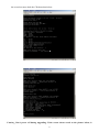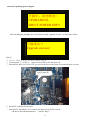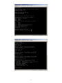
1
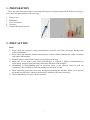
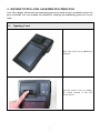
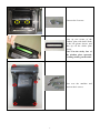
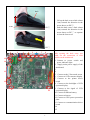
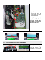
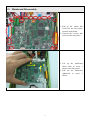
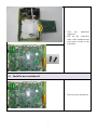
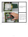
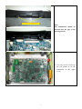
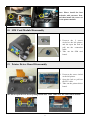
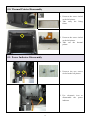
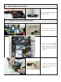
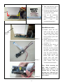
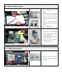
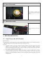
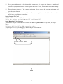
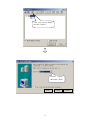
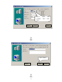
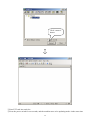
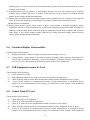
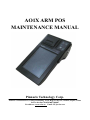
AO1X ARM POS MAINTENANCE MANUAL Pinnacle Technology Corp. Address: North 4th Floor, Guangxia Building, Torch High-Tech Zone, Xiamen, Fujian, China Service hot line: 86 0592-57100087 Net address: www.aclas.tw Email: [email protected] Contents 1. PREPARATION...................................................................................................................................1 2. PRECAUTION ....................................................................................................................................1 3. DEMOUNTING AND ASSEMBLING PROCESS ...........................................................................2 3.1. 3.2. 3.3. 3.4. 3.5. 3.6. 3.7. 3.8. 3.9. 3.10. 3.11. 3.12. 3.13. 3.14. 3.15. 3.16. 3.17. 4. Opening Crust ................................................................................................................................ 2 Customer Display Module Disassembly .......................................................................................5 Mainboard Disassembly ................................................................................................................6 Install a new mainboard .................................................................................................................7 Touch Panel Module Disassembly............................................................................................... 10 Smart Card Module Disassembly ................................................................................................ 10 Printer Module Disassembly........................................................................................................10 SIM Card Module Disassembly................................................................................................... 11 Printer Driver Board Disassembly ............................................................................................... 11 Thermal Printer Disassembly ......................................................................................................12 Power Indicator Disassembly ......................................................................................................12 RFID Module Disassembly .........................................................................................................13 Communication Board Disassembly ...........................................................................................13 Battery Disassembly ....................................................................................................................15 GPRS Disassembly ......................................................................................................................15 Buzzer Disassembly.....................................................................................................................16 Ibutton Disassembly ....................................................................................................................16 TROUBLESHOOTING ....................................................................................................................16 4.1. 4.2. 4.3. 4.4. 4.5. 4.6. 4.7. 4.8. 4.9. 4.10. 4.11. 4.12. 4.13. Cannot Turn on the AO1X Terminal............................................................................................ 16 AO1X Terminal Automatically Restart (or Power off)................................................................ 24 Cursor Beat in Fixed Position or not Accurate When Touching the Screen ................................ 24 AO1X Displays Unclearly or Has Water Ripple .........................................................................24 Printer Equipment Abnormalities ................................................................................................ 24 Customer Display Abnormalities .................................................................................................25 USB Equipment cannot be Used .................................................................................................25 Cannot Read TF Card ..................................................................................................................25 PS2 Scanner cannot Scan.............................................................................................................26 Telephone cannot be Used ...........................................................................................................26 Password Keyboard and Connector cannot be Used ...................................................................26 Causal analysis and resolution: ....................................................................................................26 Cannot Open the Drawer .............................................................................................................26 1. PREPARATION There are some necessary tools for servicing cash register, you must prepare them before servicing, so as to ensure the good quality of the servicing. 1. 2. 3. 4. 5. Electric iron Multimeter Cross screwdriver Tweezers External hexagonal wrench 1 2 3 4 5 2. PRECAUTION Notes: Know about the machine's using circumstances from the user before servicing. Backup data before maintenance. Know about the machine situation from the user, such as failure phenomenon, failure causation and relative information. Place the parts at some fixed location to avoid any part missing. Make sure to use proper parts (same brand& type as original is highly recommended) for replacement. Improper parts used may shorten the duration of the machine. Assembling or disassembling parts in power-on status is not allowed. Insert or pull out connection cable carefully to avoid any damage on the cable or parts. Static electricity protection is necessary during disassembling the machine. Make sure to ground the brand iron and wires, otherwise parts may be broken by the static electricity. Take a maintenance record for future reference. 1 3. DEMOUNTING AND ASSEMBLING PROCESS Note: This chapter will describe the demounting process in detail and give installation notices for parts of module. You can assemble the machine by following the demounting process in reverse order. 3.1. Opening Crust This is the AO1X series ARM POS Terminal. Open the printer cover by pulling the central position as the left picture shows. 2 Unscrew the 2 screws. Prize up one corner of the window plate with knife blade as the left picture shows, and then rip off the whole plate slowly. Note: Put the sticky face of the window plate upwards, avoiding sticking on the table. Turn over the machine and unscrew the 6 screws. 3 back front PIC① 1. Lift up the back crust a little (about 1cm) towards the direction as the arrow shows on PIC①. 2. Push the back curst a little (about 1cm) towards the direction as the arrow shows on PIC② to separate it from the front crust. PIC② 1 2 3 4 5 6 7 8 15 14 13 12 11 10 4 After opening the back crust, you could see the connection of each module on the mainboard. 1. Connect to power switch and power indicator light. 2. Supply main power supply of the mainboard. 3. 4. 5. Connect to the 5-line touch screen 6. Connect to LCD customer display 7. Connect to the printer driver board 8. Connect to the backlight of LCD operator display. 9. Connect to the signal of LCD operator display 10. Connect to lithium battery 11. Connect to buzzer 12. Connect to UPS power protection plate 13. Connect to communication driver board 14. 15. 3. Open the crust. 4. Take off the cables that circled on the left picture from the front crust. Note: When opening the crust, the angle between the front crust and the back crust should be vertical so as not to break flat cables. 约 90°角 Note: Open the lock before pulling out FFC cable. Otherwise, the FFC cable will be broken. 3.2. Customer Display Module Disassembly Take out the customer display towards the direction as the arrow shows on the left picture 5 3.3. Mainboard Disassembly 1. Pull up the cables that circled on the left picture from the main board. 2. Unscrew the 2 screws that circled on the left picture . 2 1. Lift up the mainboard about 1mm as arrow 1 shows in the left picture. 2. Pull out the mainboard rightwards as arrow 2 shows. 1 6 3. Turn the mainboard rightward. 4. Pull out the connection cable of the mainboard and touch panel circled on the left picture. 3.4. Install a new mainboard 1. Take out a new mainboard. 7 2. Install the connection cable between the mainboard and the touch panel. 1 3. Install the mainboard to the pressing block as arrow 1 shows first, and then press the other side of the mainboard as arrow 2 shows, so that the mainboard could place on the upper cover flatly. 2 压块 8 gap of the pressing blocks Note: The mainboard should be inserted into the gap of the pressing blocks. 4. Use two screws circled as the left picture to fix the maniboard on the upper cover. 9 3.5. Touch Panel Module Disassembly 1. Unscrew the 6 screws circled on the left picture and take out their pedestals. 2. Take out the touch panel. 3.6. Smart Card Module Disassembly 1. Unscrew the screw circled as the left picture and take away the shim. 2. Take out the smart card module as the arrow shows. 3.7. Printer Module Disassembly 1. Unscrew the 4 screws circled as the left picture and take out their pedestals. 2. Take out the printer module. 10 Note: Please install the four pedestals with tweezers first, and then install the screws to fix the printer module. 3.8. SIM Card Module Disassembly 1. Unscrew the 2 screws circled as the left picture, and the open the lock to pull out the connection cable. 2. Take out the SIM card board. 3.9. Printer Driver Board Disassembly 1. Unscrew the screw circled as the left picture. 2. Open the lock to pull out the FFC cable. 3. Take out the printer driver board. Note: Please open the lock before pulling out the FFC cable. Otherwise, the cable will be broken. 11 3.10. Thermal Printer Disassembly 1. Unscrew the screw circled as the left picture. 2. Take away the fixing frame. 3. Unscrew the screw circled as the left picture. 4. Take out the thermal printer. 3.11. Power Indicator Disassembly 1. Unscrew the two screws circled as the left picture. 2. Use electronic iron to disassemble the power indicator. 12 3.12. RFID Module Disassembly Take out the RFID module as the arrow shows. 3.13. Communication Board Disassembly 1. Unscrew the 4 screws and take out the two pedestals. 2. Pull out the connection cable from the GPRS module and UPS module that circled as the left picture. 3. Lift up the communication board as the left picture and take it out. 13 4. Take away the two pieces of communication baffle. 5. Pull up the lock that circled as the left picture and take away the FFC cable. 6. Pull out all connection cable from the communication board and take out the communication board. Installation notice: pressing blade Picture① Picture② Picture③ 14 1. Parallel insert the FFC cable to the lock set, and use pressing blade (about 3mm) to press down the lock to buckle up the cable as picture ①. 2. Install connection cables to the communication board as picture ②. 3. Install the two pieces of communication baffle. Bend the two bars (circled as picture ③) a little first, and then match the baffle with the board interface, push baffles toward the board until they could couple with each other. Make sure two bars have a good contact with the communication interface Note: While inserting the FFC cable as picture ① , Please press down it in parallel line by using the pressing tool . Otherwise, the cable will be loose and make poor contact. 3.14. Battery Disassembly 1. Rip off the tape on the battery. 2. Pull out the connection cable between the battery and the power protection module circling as the left picture. 3. Unscrew the two screws and take away the fixing plates. 4. Take off the battery. 1. 2. 3. Pull out the connection cable from the power protection module. Unscrew the screw circling as the left picture. Take off the electricity protection board. 3.15. GPRS Disassembly 1. Unscrew the two screws and take away the GPRS module. 15 3.16. Buzzer Disassembly Use alcohol to dissolve the cement and then take away the buzzer. 3.17. Ibutton Disassembly Unscrew the nut as the arrow shows. 4. TROUBLESHOOTING 4.1. Cannot Turn on the AO1X Terminal Reasons analysis: The phenomenon is called cannot turn on the terminal when the terminal of AO1X cannot be turned on after connecting with the power supply, and the power indicator isn’t on. Solutions: (1) The battery voltage is low. Please connect it with DC adapter to get power supply. If the status indicator is on, the power supply is OK. If the indicator is off, the DC adapter is broken or protected, and maybe the power supply of the DC adapter is wrong. Please check if the 220V power supply is available for the DC adapter. (2) If it can be turned on with the DC adapter and cannot be turned on without the DC adapter, check if the battery capacity is low. Please get the battery charged. If still cannot turn on the terminal, it may be the damage of battery or UPS circuit. Please renewal the battery or the UPS charging board. 16 (3) If the power indicator is on but the machine cannot work, it may be the damage of mainboard software or mainboard hardware. Please update the software first, if still cannot work, then change a new mainboard. (4) The problem or damage of the external equipment. Please remove the external equipment and reset the power button. (5) If you still cannot turn on the terminal after all steps above, please download the software and the kernel anew according to steps below: Step1:Format TF Card ① Format TF card into FAT32 form ② Copy the software to the formatted TF card through PC. Step2: Download a New Software There are two ways to download a new software but way 1 is preferential. If way 1 fails, try way 2. Way 1: ① Connect AO1X with PC by 9D6P connection cable ② Open relevant CRT in PC and open CR according to windows below Caution: Baud rate is always 115200. Click “connect” button 17 Click “new session” button, then lick “connect” Choose “Serial”, then click “Next” Next 18 Finish Cancel Choose baud “115200”, then “Next” Before Before Next rate click Cancel Click “Finish” Before Finish 19 Cancel Click “connect” button ③ Put all TF card into card slot. ④ Press the power switch for ten seconds, and the machine turns to be updating mode. At the same time 20 the screen becomes dark, the CR shows data below. Caution:Don’t power off during upgrading. If the screen shows words as the picture below, it 21 means the updating process begins. 升级中,请勿断电! UPGRADING… DON’T POWER OFF!! After finishing the updating, the screen shows words “upgrade success”, as the picture below. 升级成功! ! Upgrade success! Way 2: ① Connect AO1X with PC by 9D to 6pin serial. ② Consult point ② of Way 1,,Open relevant CRT in PC and open CR ③ Demount the back cover of AO1X, you can see the boot in the short circuit mainboard, as below. 此处为 boot 脚 ④ Put all TF card into the card slot. ⑤ Start AO1X, after about 3 to 5 seconds, the short circuit will be solved. CR shows the information below (just like Way 1): 22 23 4.2. AO1X Terminal Automatically Restart (or Power off) Causal analysis and resolution: If the AO1X is frequently power off or startup automatically, when in the use or just after startup, this should be the AO1X terminal automatically restart (or power off). Solutions: (1) Maybe the power adapter has not been connected, so the battery voltage is too low. Check if the power adapter has been connected. (2) Check whether the power adapter is connected well, whether it’s 220V, whether the indicator light of power adapter is on. (3) If this problem appears after adding or changing external devices, please first change back or remove the hardware. 4.3. Cursor Beat in Fixed Position or not Accurate When Touching the Screen Causal analysis and resolution: (1) Whether the touch screen is clean or sticks some foreign objects. Clear the foreign bodies to ensure make sure the machine is clean. (2) User can calibrate the touch screen after startup and before login the system. Specific method: fast click 5 times on the upper right of the screen, and then click in turn the crosses in 4 corners and the middle of the screen. When finishing these actions, the system hints “Calibration done”. (3) Maintenance man can login the system as manager, choose the “Screen Calibration” in management function to conduct the calibration. (4) See whether the housing is out of shape. If so, the machine should be sent back to factory for maintenance. (5) If no response or sound when touching, it’s mainly because the touch screen is broken, or the touch circuit of main board works abnormally. Please first change the touch screen for test. If this doesn’t work, then change the main board for test. 4.4. AO1X Displays Unclearly or Has Water Ripple Causal analysis and resolution: (1) Power supply or other high frequency equipments influence screen or machine (intercom, mobile phone). Make sure the AO1X terminal is away from high voltage, high frequency equipments. (2) If it’s certain that there’s no interference source, it’s maybe the problem of LCD display or main board circuit. Please first change the LCD for test. If this doesn’t work, then change the main board for test. 4.5. Printer Equipment Abnormalities Causal analysis and resolution: (1) Print unclearly; it may be bad quality of the printing paper, please use the high quality thermal 24 printing paper. Or it may be the dirt in the thermal printer, please clean the thermal printer by a piece of cotton with alcohol. (2) Print abnormally (print no picture, or print blocky pictures); no heat. The printer may be installed wrongly, please reinstall top cover of printer. If the fault still exists, it may be the broken thermal printer, please change another thermal printer. (3) Cannot print; the printer may be installed wrongly, please reinstall top cover of printer. If the fault still exists, it may be the dropping of connecting wire, trouble of pinboard, the breaking down of thermal printer or mainboard. (4) Report paper absence; please check if there is paper, or the printer is installed improperly, please reinstall the top cover; if the fault still exists, it may be the dropping of connection cable, or trouble of pinboard, or the breaking down of thermal printer or mainboard. Please check if signal cable or power cable drops, if not, please change another pinboard for testing, and then change another thermal printer, finally change another mainboard. 4.6. Customer Display Abnormalities Causal analysis and resolution: (1) Display abnormally; customer display is broken, please change a new one. (2) Cannot display;please check if the cable is normal, including if the connector drops and if the cable breaks. If nothing is abnormal, it may be the problem of customer display, please change a new one. Or if it is the problem of mainboard, please change a new mainboard. 4.7. USB Equipment cannot be Used Causal analysis and resolution: (1) Check the status of USB ; (2) USB equipment cannot be too long, or it may be not provided enough power. (3) Check if the big cable between the communication board and the mainboard looses or drops. (4) It may be the problem of communication board or circuit abnormalities of mainboard. Please change a new communication board for testing, if it still doesn’t work, change a new mainboard for testing again. 4.8. Cannot Read TF Card Causal analysis and resolution: (1) Check the status of TF equipment; (2) Check if TF card inserted in the right place; (3) Check if TF card slot of the communication board is broken or out of shape; (4) Check if the big cable between the communication board and the mainboard looses or drops. (5) It may be the problem of communication board or circuit abnormalities of mainboard. Please change a new communication board for testing, if it still doesn’t work, change a new mainboard 25 for testing again. 4.9. PS2 Scanner cannot Scan Causal analysis and resolution: (1) Check the status of scanner ; (2) Check if PS2 connector inserted in right place, push hard when you try to insert it.; (3) PS2 socket may contacts poor after being used for a long time, please change a new PS2 socket; (4) Check if the big cable between the communication board and the mainboard looses or drops; (5) It may be the problem of communication board or circuit abnormalities of mainboard. Please change a new communication board for testing, if it still doesn’t work, change a new mainboard for testing again. 4.10. Telephone cannot be Used Causal analysis and resolution: (1) Check the status of telephone (2) Check if the 6pin crystal connector of telephone becomes oxidized or dirty; (3) Check if the 6pin socket becomes oxidized , dirty or out of shape; (4) Check if the big cable between the communication board and the mainboard looses or drops; (5) It may be the problem of communication board or circuit abnormalities of mainboard. Please change a new communication board for testing, if it still doesn’t work, change a new mainboard for testing again. 4.11. Password Keyboard and Connector cannot be Used 4.12. Causal analysis and resolution: (1) (2) (3) (4) (5) check the status of keyboard Check if the 6pin crystal connector becomes oxidized or dirty; Check if the 6pin socket becomes oxidized , dirty or out of shape; Check if the big cable between the communication board and the mainboard looses or drops; It may be the problem of communication board or circuit abnormalities of mainboard. Please change a new communication board for testing, if it still doesn’t work, change a new mainboard for testing again. 4.13. Cannot Open the Drawer Causal analysis and resolution: 26 (1) (2) (3) (4) (5) (6) Check if the connector of drawer fits the definition of SENOR standard drawer connector; Check if the 6pin crystal connector becomes oxidized or dirty Check if the 6pin socket becomes oxidized , dirty or out of shape; Check if the fourth drawer connector is under AC 20V; Check if the big cable between the communication board and the mainboard looses or drops; It may be the problem of communication board or circuit abnormalities of mainboard. Please change a new communication board for testing, if it still doesn’t work, change a new mainboard for testing again. 27