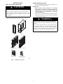
1
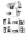
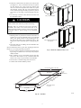
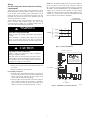
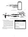
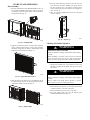
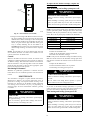
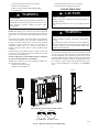
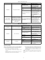
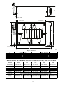
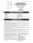
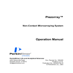
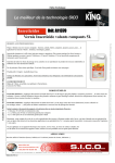
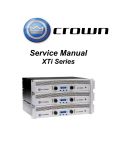
PGAP
Germicidal Air Purifier
Sizes 1620, 1625, 2020, 2025, 2420
Installation Instructions
NOTE: Read the entire instruction manual before starting the
install.
TABLE OF CONTENTS
PAGE
INTRODUCTION . . . . . . . . . . . . . . . . . . . . . . . . . . . . . . . . . . . 1
HOW IT WORKS . . . . . . . . . . . . . . . . . . . . . . . . . . . . . . . . . . . 1
SAFETY CONSIDERATIONS . . . . . . . . . . . . . . . . . . . . . . . . . 1
APPLICATION CONSIDERATIONS . . . . . . . . . . . . . . . . . . . . 2
INSTALLATION . . . . . . . . . . . . . . . . . . . . . . . . . . . . . . . . . . . . 3
START--UP AND OPERATION . . . . . . . . . . . . . . . . . . . . . . . . 9
MAINTENANCE . . . . . . . . . . . . . . . . . . . . . . . . . . . . . . . . . . . 10
TROUBLESHOOTING . . . . . . . . . . . . . . . . . . . . . . . . . . . . . . 11
ERROR AND STATUS CODES . . . . . . . . . . . . . . . . . . . . . . . 12
A11332
Fig. 1 -- PGAP Unit
INTRODUCTION
SAFETY CONSIDERATIONS
Congratulations for selecting the Air Purifier for your home
comfort system! The Air Purifier is proven to remove and kill
airborne germs and allergens, including viruses and bacteria. The
Air Purifier is a cornerstone of Healthy Home Solutions for
providing healthier, cleaner air in your home.
Improper installation, adjustment, alteration, service, maintenance,
or use can cause explosion, fire, electrical shock, or other
conditions which may cause death, personal injury or property
damage. Consult a qualified installer, service agency or your
distributor or branch for information or assistance. The qualified
installer or agency must use factory--authorized kits or accessories
when modifying this product. Refer to the individual instructions
packaged with the kits or accessories when installing.
Follow all safety codes. Wear safety glasses, protective clothing,
and work gloves. Have a fire extinguisher available. Read these
instructions thoroughly and follow all warnings and cautions
included in literature and attached to the unit. Consult local
building codes and the current edition of the National Electrical
Code (NEC) NFPA 70.
In Canada, refer to the current editions of the Canadian Electrical
Code CSA C22.1.
HOW IT WORKS
The Air Purifier provides extremely high filtration performance
while killing captured contaminants, including viruses and
bacteria. The Air Purifier treats the entire air--stream through a state
of the art, three--stage process.
In stage one, the particles are electrically charged by a
precision--point ionization array as they enter the Air Purifier.
In stage two, the charged particles are electrically attracted to the air
purification cartridge, which is located within an electric field.
In stage three, captured particles are killed by electrical current
flow and ion bombardment.
The Air Purifier is Listed to applicable UL Standards and
requirements by Underwriters Laboratories Inc.
Ce purificateur d’air est conforme aux normes applicables dites
‘UL’, de Underwriters Laboratories Inc.
on
Recognize safety information. When you see this symbol
the unit and in instructions or manuals, be alert to the potential for
personal injury. Understand the signal words DANGER,
WARNING, and CAUTION. These words are used with the
safety--alert symbol. DANGER identifies the most serious hazards,
which will result in severe personal injury or death. WARNING
signifies hazards, which could result in personal injury or death.
CAUTION is used to identify unsafe practices, which may result
in minor personal injury or product and property damage. NOTE
is used to highlight suggestions which will result in enhanced
installation, reliability, or operation.
APPLICATION CONSIDERATIONS
!
WARNING
Turning Vanes
If the Air Purifier is installed adjacent to a 90_ duct elbow, turning
vanes should be added inside duct to improve air distribution
across the face of the Air Purifier.
HIGH VOLTAGE HAZARD
Electrical Power and Flow Sensing
Failure to follow this warning could result in personal injury
or death.
The Air Purifier should only be powered when airflow is present.
The furnace control EAC terminals provide power only when the
furnace blower is operating. Air Purifier models PGAPAXX1625
and PGAPAXX2025 are designed to be powered from the
electronic air cleaner (EAC) terminals on a furnace electronic
control. If EAC terminals are not available, the Accessory Flow
Sensor Kit, model KIT--160--000, must be purchased for use with
the Air Purifier. Air Purifier models PGAPAXX1620,
PGAPAXX2020, and PGAPAXX2420 include the flow sensor as
standard equipment as they are designed primarily to be installed
with fan coil air handlers. A Flow Sensor Jumper Accessory Kit,
KIT--161--000 is available should there be a need to use Air
Purifier
model
PGAPAXX1620,
PGAPAXX2020,
or
PGAPAXX2420 with a furnace that has EAC terminals.
This Air Purifier utilizes high voltage. If you notice water
running into or around the Air Purifier, water stains on the
purifier cartridge or on the Enhancement Module walls or
cabinet, shut off the Air Purifier and call your service provider.
The Air Purifier is designed for use in the return air duct of a
forced air heating, cooling, and ventilation system. Although
designed to be a robust air purification system, the Air Purifier is
not designed to operate when wet. Operation of the Air Purifier in
a wet environment will result in less than optimal performance and
a possible safety hazard. As such, particular attention must be paid
to the following paragraphs regarding installation near air
conditioning coils and humidifiers.
The Air Purifier should be installed in a system so that all the
return air is circulated through the Air Purifier. It should be located
upstream of both the furnace and the air conditioning evaporator
coil. This will help keep the furnace and evaporator coil clean and
prevent condensation from forming within the Air Purifier.
Humidifiers
An evaporative humidifier can be mounted upstream of the Air
Purifier but the recommended location of any humidifier is
downstream of the Air Purifier. It is necessary to install atomizing
humidifiers downstream of the Air Purifier because hard water salt
deposits and water droplets may damage Air Purifier.
Ensure that the humidifier installation will not allow water or water
droplets to enter the Air Purifier because it may cause electrical
arcing or damage the Air Purifier.
NOTE: For fan coil installations, do not install the humidifier in
the fan coil access doors or cabinet.
Inspect for plugged drains and maintain humidifier drain lines on a
regular basis to avoid overflow of water into the Air Purifier. The
recommended inspection should be done at every change of the
Air Purifier cartridge (generally 8--12 months).
!
Electrical Power Fusing
Air Purifier models PGAPAXX1620, PGAPAXX2020, and
PGAPAXX2420 include in-line fuses necessary for installation
with fan coil air handlers. Air Purifier models PGAPAXX1625 and
PGAPAXX2025 do not include in-line fuses as they are designed
to be powered from the electronic air cleaner (EAC) terminals on a
furnace electronic control, which are already properly
current-limited for Air Purifier application. If there is a need to use
Air Purifier model PGAPAXX1625 or PGAPAXX2025 with a
230VAC fan coil air handler or other high-current source, the
Accessory Fuse Kit KFAPS0110KIT must be ordered and installed
per the instructions included within the kit.
Accessory Safety Screen
!
ELECTRICAL OPERATION HAZARD
Failure to follow this warning could result in personal injury
or death.
The Air Purifier contains high voltage electrodes and as
supplied is designed to be installed in a completely enclosed
duct system in order to prevent access to high voltage during
operation of the purifier. If there is a need to operate the
purifier as the first element in a duct system (thereby locating
the inlet of the purifier in a position that could be touched
during operation), the Accessory Safety Screen Kit, listed in
the table below, must be purchased for use with the purifier.
WARNING
HIGH VOLTAGE HAZARD
Failure to follow this warning could result in personal injury
or death.
This Air Purifier utilizes high voltage. If you notice water
running into or around the Air Purifier, water stains on the
purifier cartridge or on the Enhancement Module walls or
cabinet, shut off the Air Purifier and call your service provider.
KIT MODEL NUMBER
KIT--- 170--- 000
KIT--- 171--- 000
KIT--- 172--- 000
KIT--- 173--- 000
KIT--- 174--- 000
Transitions
If the return air duct or furnace openings do not fit the Air Purifier
cabinet openings, gradual transitions are recommended to reduce
air turbulence and maximize efficiency. No more than 45_ (about
8.5 inches per running ft.) of expansion should be used on each
side of the transition fitting.
WARNING
AIR PURIFIER MODEL NUMBER
PGAPAXX1625
PGAPAXX2025
PGAPAXX1620
PGAPAXX2020
PGAPAXX2420
Duct Hardware Upstream of Purifier
Any equipment mounted in the duct or duct parts such as turning
vanes installed in the duct upstream of the purifier must be kept at
least 1.25 inches from the front face of the Air Purifier.
2
INSTALLATION
Identify Mounting Location
Check Air Purifier Components
!
CAUTION
CUT HAZARD
Failure to follow this caution may result in personal injury.
Sheet metal parts may have sharp edges or burrs. Use care and
wear appropriate protective clothing and gloves when
handling parts.
1. Identify a mounting orientation for the Air Purifier in the
return air duct (see Figures 3 and 4).
IMPORTANT:
2. Ensure airflow direction through the Air Purifier
matches the arrows on the face of the Air Purifier cartridge and those on the label on the front of the cabinet.
The Air Purifier can be rotated 180_ to accommodate
the cabinet orientation.
3. The location of the Air Purifier should be readily accessible.
Enough room should be provided for periodic replacement
of the Air Purifier cartridges.
!
Carefully remove all items from the box. See Fig. 2.
WARNING
ELECTRIC SHOCK AND UNIT DAMAGE HAZARD
Failure to follow this warning could result in personal injury
or death.
Only a trained, experienced service person should install the
Air Purifier. A thorough check of the unit installation should
be completed before unit operation. Before performing
installation, service or maintenance operations on unit, turn off
all power to unit. Tag disconnect switch with lockout tag.
Door (x1)
Enhancement Module (x1)
Installation Manual
Cabinet (x1)
Air Purification Cartridge (x1)
Installation Components
(in accessory bag)
A11330
Fig. 2 -- Air Purifier Components
3
NOTE:
Mounting on this side
requires the cabinet
to be rotated 180° for
correct air flow. This
places the hinged end
the door at the top of
the cabinet and the
handle/latch at the
bottom.
Air Flow
Air Flow
Air Flow
Air Flow
A11333
Fig. 3 -- Air Purifier Cabinet Orientation
Downflow 14” Furnace
with Top Mount
Upflow 14” Furnace
with Bottom Mount
Horizontal 14” Furnace
with Side Mount
Upflow Furnace
Plenum
Box
Downflow 24” Furnace
with Top Mount
Upflow 24” Furnace On Stand
with Bottom Mount
Horizontal 24” Furnace
Upflow Furnace
with Plenum Box
A11331
Fig. 4 -- Air Purifier Cabinet Orientation with Transition
4
Return Duc
t
Return D
Top Mount
uct
Side Mount
Bottom Mount
A11368
Fig. 5 -- Mounting Air Purifier Cabinet
Mount Cabinet
!
WARNING
ELECTRICAL SHOCK HAZARD
Failure to follow this warning could result in personal injury
or death.
Before installing or servicing system, always turn off main
power to system. There may be more than one disconnect
switch. Lock out and tag switch with a suitable warning label.
A11493
!
Fig. 6 -- Removing Filter
CAUTION
UNIT DAMAGE HAZARD
Failure to follow this caution may result in equipment
damage.
Cabinets will support a maximum weight of 400 lbs/181 kg
when installed beneath a vertical furnace or air--handling
unit. When setting furnace on cabinet, do not drop it into
place. Position the furnace correctly on the cabinet to prevent
a corner from slipping down and damaging the cabinet or its
components.
1. Turn off power to the heating and cooling system.
2. Remove the existing furnace filter and discard. Excessive
system static may result if the Air Purifier is used with other
filtration devices.
3. Remove the Air Purifier cartridge and enhancement module
from the Air Purifier cabinet. See Fig. 6 and 7.
4. If the air purifier is to be mounted in a side--flow application, affix the adhesive--backed support foot to the side of
the purifier that will be on the floor, near the rear of the purifier, as shown in Fig. 8.
A11494
Fig. 7 -- Removing FEM
A11545
Fig. 8 -- Installation of Support Foot
5
5. Position the cabinet between the furnace and return air duct
(see Figures 3, 4, and 5). A transition duct may be required.
On some furnaces, one or more screws may interfere with
the ease of removal of the purifier door. In this case, replace
the interfering screw(s) with pop rivet(s). Removing the
screws without replacing them with pop rivets may have an
adverse effect on air sealing or structural integrity of the furnace.
6. Use foam tape or silicone sealant between the furnace and
the Air Purifier cabinet.
!
Step 1: Remove screw
CAUTION
UNIT DAMAGE HAZARD
Failure to follow this caution may result in unit damage.
Mounting holes are provided for duct work and furnace
attachment. The screws on the down--stream side of the
cabinet should be installed so that the screw heads are inside
Air Purifier cabinet to prevent damage to the Air Purifier
cartridge.
7. Mounting holes are provided for ductwork and furnace attachment. To access the mounting holes on the upstream
flange of the purifier adjacent to the incoming power wiring, slide off the wiring cover as illustrated in Fig. 9. The
wiring cover must be reinstalled prior to operating the purifier.
8. Seal seams with tape or caulking after the Air Purifier cabinet has been secured.
Special consideration must be given when applying the 2025 Air
Purifier to a 24 1/2 inch (622 mm) wide furnace.
1. Prepare transition, following recommended transition drawing (see Fig. 10). Fabricate a 2 1/4 inch (57 mm) tall (minimum) transition.
2. Place transition on top of Air Purifier. Secure with sheet
metal screws. Place furnace on top of transition. Make sure
furnace rests evenly on top of transition and Air Purifier.
3. Secure furnace to transition using sheet metal screws.
4. Continue with normal installation practices.
Step 2: Remove electrical cover
from cabinet
A11546
Fig. 9 -- Removal of Electrical Tray Cover
Furnace Casing Width 24 1/2” (622)
B
Rear Bracket
S
2 1/4” (57)
B
ide
rac
ke
t
S
Front Bracket
B
ide
rac
ke
5/8” (16)
Flanges
(Where Shown)
t
22 7/8” (581)
(Outside)
NOTE: Weld 3 places
in 4 corners
19 1/8” (486)
A
(Inside Opening)
Air Purifier Outlet
A11490
Fig. 10 -- Transition
6
Wiring
For the wiring in the furnace and fan coil wiring
compartments
The incoming power supply wiring and connections for the air
purifier should be routed away from the output duct of the furnace
or fan coil unit, and the incoming power connections for the air
purifier in the furnace or fan coil unit must be properly rated. The
maximum rated current draw for the furnace 120VAC and fan coil
230VAC air purifiers is 0.3 Amps.
The installation involves direct connection to the duct and to a
furnace controller EAC terminal output. The field wiring
connection shall be suitable for a maximum possible rating of
90_C of the field wiring terminal box/terminals.
!
NOTE: The Air Purifier should only be powered when airflow is
present. The furnace control EAC spade connections, shown in
Fig. 12, provide power only when the furnace blower is operating.
Air Purifier models PGAPAXX1625 and PGAPAXX2025 are
designed to be powered from the electronic air cleaner (EAC)
terminals on a furnace electronic control. If EAC terminals are not
available, the Accessory Flow Sensor Kit, model KIT--160--000,
must be purchased for use with the Air Purifier.
FURNACE AIR
PURIFIER ASSEMBLY
WARNING
ELECTRICAL SHOCK HAZARD
Failure to follow this warning could result in personal injury
or death.
BLK
LINE 1 IN
(EAC-1)
WHT
120 VAC
INPUT POWER
NEUTRAL IN
(EAC-2)
GRN
CHASSIS
GROUND
Before installing or servicing system, always turn off main
power to system. There may be more than one disconnect
switch. Lock out and tag switch with a suitable warning label.
A11465
!
Fig. 11 -- Furnace Installation
CAUTION
Sample Furnace Circuit Board
EQUIPMENT DAMAGE HAZARD
1 2 3
LHT
OFF
DLY
Y1 DHUM G
TEST/TWIN
PL T
HUM
Use terminals to connect the
power cord wires to the furnace
EAC-1 & 2, & ground terminals
ACRDJ
COM WW1 Y/Y2
24V
This unit cannot be powered directly from blower motor
leads. Voltages can exceed 190 VAC (120v motors). Do not
wire directly to blower motor. Wiring to blower motor will
damage power supply and void warranty.
ON
OFF
W2
Failure to follow this caution may result in equipment
damage or improper operation.
0.5-AMP024 V AC
R
SEC-1
SEC-2
NEUTRAL-L2
PL3
OD E
EA C-2
PL1
EAC-2 TERMINAL
LE D
FUSE 3-AMP
S TAT
US C
1
1
BL W
BHI/LOR
BHT/CLR
BL WR
HI HEA T
IDM
1-AMP@115 V AC
EA C-1
PR-1
PL2
L1
SP ARE-2
1
COOL
SP ARE-1
IHI/LOR
HSIR
IDR
LO HEA T
1. Ensure power has been removed from the heating and cooling system.
2. Turn the Air Purifier power switch off.
For mounting on furnaces:
1. Route the power conduit from the purifier to a knockout on
the furnace that provides access to the EAC terminals on the
furnace control board. Affix the end of the conduit to the
furnace using the included conduit fitting.
2. Attach the quick connect terminals on the wires exiting the
power conduit assembly to the furnace EAC--1 and EAC--2
spade connections. Attach the ground ring terminal on the
third wire to furnace chassis ground. See Fig. 11 and 12.
HSI HI LO
EAC-1 TERMINAL
A11491
Fig. 12 -- Air Purifier Connection to Furnace
7
A12250
Fig. 13 -- Fan Coil Schematic
A12251
Fig. 14 -- In--line Fuse Installation Illustration
For mounting to fan coil air handlers:
1. Route the power conduit from the purifier to a knockout on
the fan coil air handler that provides access to the incoming
power wiring compartment. Affix the end of the conduit to
the fan coil air handler using the included conduit fitting.
2. Remove the yellow and black primary wires from the fan
coil air handler transformer terminals and connect the quick
connect “piggyback” terminals of the in-line fused leads exiting the air purifier power conduit assembly to the transformer terminals. Reconnect the yellow and black primary
wires to their respective transformer terminals on the
“piggyback” terminals. Attach the ground ring terminal on
the third wire to fan coil air handler chassis ground. See
Figures 13 and 14.
NOTE: Power connections are to be made inside the fan coil
wiring compartment per local electrical codes, and the two in-line
fuses that are provided with the air purifier must be installed in the
fan coil wiring compartment.
!
CAUTION
UNIT COMPONENT DAMAGE HAZARD
Failure to follow this caution may result in equipment
damage or improper operation.
For Furnace Purifiers:
Black Lead -- Connect to Hot (L1) or EAC--1 when
provided.
White Lead -- Connect to Neutral (L2) or EAC--2 when
provided.
Green/Ground Lead -- Connect to Appliance Ground
(Chassis).
For Fan Coil Purifiers:
Black Lead -- Connect to L1
White Lead -- Connect to L2
Green Lead -- Connect to Appliance Ground (Chassis)
8
START--UP AND OPERATION
4. Insert the desired brand logo into the front of the door panel. To insure that the logo is installed in the proper orientation, first attach the door to the purifier and then snap the
Carrier or Bryant logo into place with the text in upright position. See Fig. 18.
5. Affix the “Captures & Kills” label to the front of the purifier door as desired.
Final Assembly
1. Install the Filter Enhancement Module (FEM) into the cabinet, insuring that FEM is held firmly in place by the retention springs and that the high voltage connector/handle is
facing outward. See Fig. 15.
Airflow
A11497
Fig. 18 -- Attach Logo
A11495
Fig. 15 -- Installing FEM
Checking Air Purifier Operation
2. Apply the desired brand label to the filter. Select either the
Carrier or Bryant label from the accessory bag containing
installation components and affix it to the filter frame in the
designated location as illustrated in Fig. 16.
!
WARNING
ELECTRICAL SHOCK HAZARD
Failure to follow this warning could result in personal injury
or death.
Before installing or servicing system, always turn off main
power to system. There may be more than one disconnect
switch. Lock out and tag switch with a suitable warning label.
1. Attach the Air Purifier door to the cabinet. The power supply will not energize the Air Purifier if the door is not properly in place.
!
WARNING
CARBON MONOXIDE HAZARD
A11498
Fig. 16 -- Apply Filter Brand Label
Failure to follow this warning could result in personal injury
or death.
3. Slide the filter into the cabinet next to the FEM with the filter pull--tab facing outward and paying particular attention
to the airflow direction arrows. See Fig. 17.
Do not remove door during blower operation or operate
blower with door removed or improperly latched.
2. Turn the HVAC system power on and adjust the thermostat
or System Control to activate the system fan.
3. Turn the Air Purifier power switch to on position.
4. The green indicator light above the Air Purifier power
switch should illuminate (see Fig. 19).
Airflow
A11496
Fig. 17 -- Replace Filter
9
To replace the Air Purifier cartridge, complete the
following steps:
Turn the heating and cooling system power off.
Green Power
Indicator
!
WARNING
ELECTRICAL SHOCK HAZARD
Failure to follow this warning could result in personal injury
or death.
Before installing or servicing system, always turn off main
power to system. There may be more than one disconnect
switch. Lock out and tag switch with a suitable warning label.
A11369
Fig. 19 -- Power Indicator (Green LED)
5. This green indicator light will illuminate when the Air Purifier door is installed, the power switch is in the ON position
AND the furnace blower is running. If a flow sensor (model
KIT--160--000) is installed in the Air Purifier and there is no
airflow, the green indicator light will blink slowly (once
every 3 seconds) indicating that the Air Purifier is in
STANDBY mode. If a flow sensor is not installed, the green
indication light should go off when the blower stops running.
NOTE: For information on the green indicator light status and
error conditions, See Table 1 for status codes or Table 2 for error
codes in section Error and Status Codes.
Control
When the Air Purifier is used with a Control, the Control can be
configured to remind the homeowner when it is time to change the
Air Purifier cartridge. This maintenance reminder can be based on
either the TrueSenset dirty filter algorithm or time. The installer
should use their discretion to select the most appropriate option
based on the initial system static pressure.
Maximizing Performance
NOTE: Use of any filter cartridge in the Air Purifier other than the
genuine replacement purifier cartridges listed in the table below
will likely result in poor performance and may constitute a safety
hazard. Do not use any third--party air filters in the Air Purifier.
WARNING
PGAPXCAR1625
PGAPAXX2025
PGAPXCAR2025
PGAPAXX1620
PGAPXCAR1620
PGAPAXX2020
PGAPXCAR2020
PGAPAXX2420
PGAPXCAR2420
!
WARNING
CARBON MONOXIDE HAZARD
MAINTENANCE
!
REPLACEMENT MEDIA CARTRIDGE
PGAPAXX1625
1. Turn the Air Purifier switch to the off position.
2. Remove the Air Purifier door.
3. Slide out the old Air Purifier cartridge and discard.
4. Install the new Air Purifier cartridge.
NOTE: Verify that the Air Purifier cartridge is installed correctly.
Make sure that the arrows on the Air Purifier cartridge point in the
same direction as airflow and match the arrows on the label on the
cabinet.
5. Replace the Air Purifier door.
6. Turn the Air Purifier switch to the on position.
7. Turn heating and cooling system power on.
Maximum air purification performance is obtained when the
furnace blower is set for continuous operation on the thermostat or
Control.
The Air Purifier is designed to require minimal maintenance.
Maintenance is limited to the periodic replacement of the air
purification cartridge and inspection/brush cleaning of the
ionization array. Frequency of Air Purifier cartridge replacement
and cleaning of the ionization array may vary depending on
ductwork design and local environmental conditions, generally
6--9 months.
PURIFIER MODEL
Failure to follow this warning could result in personal injury
or death.
Do not remove door during blower operation or operate
blower with door removed or improperly latched.
At the time of Air Purifier cartridge replacement, if a powdery
residue is noticed on the tips of the points in the ionization array,
proceed to clean them by completing the following steps.
Turn heating and cooling system power off.
!
FIRE HAZARD
WARNING
Failure to follow this warning could result in personal injury
or equipment damage.
ELECTRICAL SHOCK HAZARD
Use of non--factory approved filter cartridge will void the
warranty and may cause damage due to fire.
Failure to follow this warning could result in personal injury
or death.
Before installing or servicing system, always turn off main
power to system. There may be more than one disconnect
switch. Lock out and tag switch with a suitable warning label.
10
1.
2.
3.
4.
Turn the Air Purifier switch to the off position.
Remove the Air Purifier door.
Slide out the Filter Enhancement Module (FEM).
Clean the FEM.
!
7. Turn the Air Purifier switch to the on position.
8. Turn heating and cooling system power on.
TROUBLESHOOTING
!
WARNING
CAUTION
SAFETY HAZARD
CUT HAZARD
Failure to follow this warning could result in personal injury.
Failure to follow this caution may result in personal injury or
equipment damage.
Sheet metal parts may have sharp edges or burrs. Use care and
wear appropriate protective clothing and gloves when
handling parts.
The following instructions are for use by qualified personnel
only.
NOTE: Best cleaning tools: 5 inch (127 mm) handle paint brush
with 2 inch (51 mm) width (or greater) brush point (synthetic or
natural bristle) or vacuum cleaner with brush attachment. See Fig.
20.
Gently stroke the ionization pins with the brush. Use a gentle back
and forth brushing motion to clean any small accumulations from
the tips of the points. If desired, use a vacuum cleaner with brush
attachment to gently vacuum the frame and components of
enhancement module. Also, if an Accessory Safety Screen is
installed, vacuum the Safety Screen to remove accumulated dust
and debris.
If further cleaning of the FEM is needed, it may be washed with
soap and water and/or rinsed off with water. It should not be placed
in a dishwasher or in boiling water.
NOTE: If using water to clean the FEM, it must be completely
dry before inserting back into the Air Purifier.
Additionally, care must be taken when handling the FEM due to
the sharp points on the ionizer.
5. Slide in enhancement module.
6. Replace the Air Purifier door.
!
WARNING
ELECTRICAL SHOCK HAZARD
Failure to follow this warning could result in personal injury
or death.
The following procedures will expose electrical components.
Disconnect power between checks and proceed carefully. Only
a trained, experienced service person should install and/or
troubleshoot the Air Purifier.
The Air Purifier is equipped with a power indicator light located on
the door (see Fig. 19). This power indicator light will illuminate
when the Air Purifier door is installed, the power switch is in the
on position, AND the furnace blower is running. If a Flow Sensor
Kit (model KIT--160--000) is installed in the Air Purifier and there
is no airflow, the power indicator light will blink slowly (once
every 3 seconds) indicating that the purifier is in “STANDBY”
mode.
Top View
30°
POINTS ARE SHARP! BE VERY CAREFUL DURING CLEANING.
Tip of point with residue
Tip of point after cleaning
A11370
Fig. 20 -- Removal of Deposits from Ionization Pins
11
ERROR AND STATUS CODES
The error codes and status codes are shown in the following tables.
NOTE: The green indicator light on door cover shown in Fig. 19, Power Indication (Green LED).
Table 1 – Operating Status Codes
INDICATOR LIGHT CODE
OFF
EXPLANATION
No incoming AC power to
air purifier control electronics
POSSIBLE CAUSE
Normal operation when airflow is
not present for models without flow
sensor due to AC power to purifier
being off at furnace control board
(EAC terminals).
ON/OFF power switch turned to
OFF
Power to entire system is off
(furnace and air purifier).
Blown fuse or tripped circuit
breaker for HVAC system
Misaligned or damaged purifier
door
ON (continuously)
FLASHING
(1 flash every 4 seconds)
Air purifier on
Standby Mode
Damaged or disconnected
incoming power wiring
Normal operation when airflow is
present.
Normal operation when airflow is
not present for models with flow
sensor.
Ions detected in airflow due to missing replaceable filter element
Debris is covering airflow sensor
(for models including an airflow
sensor).
Flow sensor is damaged (for
models including an airflow sensor).
Flow sensor bypass assembly is
damaged (for models without an
airflow sensor).
One or more of the three airflow
sensor contact springs on purifier
cabinet downstream rail are bent or
damaged.
12
RECOMMENDED ACTION
Turn purifier power switch to ON
position
Check that the HVAC system is
switched on.
Replace fuse or reset circuit
breaker. Call for service if problem
reoccurs.
Insure that door is undamaged and
properly installed on purifier
cabinet.
Call for service
Place filter in air purifier.
Make sure flow sensor is clean and
unobstructed
Replace flow sensor, available as
replacement kit (KIT--- 160--- 000).
Replace flow sensor bypass
assembly, available as
replacement kit (KIT--- 161--- 000).
Replace flow sensor contact spring
assembly, included as part of the
flow sensor kits (KIT--- 160--- 000 and
flow sensor bypass kit
KIT--- 161--- 000).
Table 2 – Start--Up Error Codes
INDICATOR LIGHT CODE
EXPLANATION
POSSIBLE CAUSE
No filter installed
Filter installed incorrectly.
Wrong type of filter installed
2 FLASHES
Filter ground circuit fault
Wet filter
Damaged filter contact spring on
door assembly
RAPID FLASHING
(5 flashes per second)
LED Flashes for 10 seconds when
AC power is turned on indicating a
previously stored error code code
will be displayed after 10 seconds.
Purifier will not operate until cause
of error condition is rectified and
purifier is reset.
An error code was registered in the
purifier controls prior to the purifier
being turned off.
RECOMMENDED ACTION
Place filter in air purifier.
Install filter in correct orientation as
indicated by airflow direction
arrows on cabinet and filter.
Install a genuine air purifier
replacement filter.
Call service to locate and eliminate
the source of water on the filter and
replace the filter with a new filter.
Verify that filter contact springs
mounted on door are properly
contacting the aluminum contact
pads on the filter and not
contacting the cabinet or door
back. If springs are broken or damaged replace the door
assembly.
The purifier controls may be reset
during the 10 seconds in which the
LED is flashing rapidly. See the
reset procedure section of this
document for resetting the
electrical controls. If the problem
persists, follow the actions
recommend in Table 3 for the
stored error code or call service.
Table 3 – Operating Error Codes
INDICATOR LIGHT CODE
EXPLANATION
4 FLASHES
Ionizer / filter current imbalance
5 FLASHES
Over--- current fault
6 FLASHES
Arc detected
RESET PROCEDURE
When the rapid flashing code occurs on the green light, the
controls for the high voltage need to be reset. To reset the controls,
the power switch needs to be turned on and off for three cycles.
1. Turn off power by depressing the power switch.
2. Wait approximately 2 seconds before turning the power
back on.
3. Wait approximately 2 seconds before turning the power off.
4. Repeat Steps 2 and 3 for two more on/off cycles.
POSSIBLE CAUSE
Dirty Filter Enhancement Module
(FEM).
Damaged Filter Enhancement
Module (FEM).
Excessively dirty Damaged Filter
Enhancement Module (FEM) and/or
filter.
RECOMMENDED ACTION
Clean/service air purifier unit.
Replace the filter enhancement
module.
Clean/service air purifier unit.
Call service to locate and eliminate
the source of water in the air
Wet Damaged Filter Enhancement
purifier. Verify that the purifier FEM
Module (FEM) and/or filter.
and cabinet are clean and replace
filter with a new filter.
Damaged filter.
Replace the filter element.
Damaged Filter Enhancement
Replace the filter enhancement
Module (FEM).
module.
Remove foreign object from air
purifier and insure purifier is clean
Foreign object inside air purifier.
and undamaged.
Damaged filter.
Replace the filter element.
Damaged Filter Enhancement Mod- Replace the filter enhancement
ule (FEM)
module.
Remove foreign object from air
purifier and insure purifier is clean
Foreign object inside air purifier.
and undamaged.
5. After the three on/off cycles are completed, turn on power
by depressing the power switch on. The rapid flashing code
on the green light should no longer be displayed . If the rapid flashing code on the green light is still displayed, repeat
Steps 1 through 5.
NOTE: By resetting the air purifier controls the issue with air
purifier will need ot be addressed by cleaning or servicing the air
purifier.
13
E
0.91 / 22.99
1.19 / 30.33
1.94 / 49.23
D
C
B
A
2X 1.02 / 25.88
A11334
Fig. 21 -- Dimensions
UNIT
A
B
C
D
E
1625
2025
27.68” / 703.0 mm
25.28” / 642.1 mm
17.49” / 444.2 mm
21.19” / 538.2 mm
18.48” / 469.3 mm
22.18” / 563.3 mm
1620
17.49” / 444.2 mm
18.48” / 469.3 mm
7.25” / 184.2 mm
2020
24.68” / 626.8 mm
22.28” / 565.9 mm
21.19” / 538.2 mm
22.18” / 563.3 mm
2420
24.69” / 627.1 mm
25.68” / 652.2 mm
REPLACEMENT FILTERS, REPLACEMENT COMPONENT KITS, AND ACCESSORIES
Air Purifier Model
PGAPAXX
Filter Enhancement
Module (FEM)
Front Door including
Power Supply
Flow Sensor
Flow Sensor Bypass
Front Screen
Accessory
240 VAC Equipment
Accessory Kit
Replacement filter
Cartridge
(2--- Pack)
1625
2025
1620
2020
2420
KIT--- 140--- 000
KIT--- 141--- 000
KIT--- 142--- 000
KIT--- 143--- 000
KIT--- 144--- 000
KIT--- 150--- 000
KIT--- 151--- 000
KIT--- 150--- 000
KIT--- 151--- 000
KIT--- 152--- 000
KIT--- 160--- 000 (Included as standard with Models PGAPAXX1620, PGAPAXX2020, and PGAPAXX2420)
KIT--- 161--- 000 (Included as standard with Models PGAPAXX1625 and PGAPAXX2025)
KIT--- 170--- 000
KIT--- 171--- 000
KIT--- 172--- 000
KIT--- 173--- 000
KIT--- 174--- 000
KFAPS0110KIT
(Included as standard with Models PGAPAXX1620, PGAPAXX2020, and PGAPAXX2420)
PGAPXCAR1625--- A02 PGAPXCAR2025--- A02 PGAPXCAR1620--- A02 PGAPXCAR2020--- A02 PGAPXCAR2420--- A02
14
15
Copyright 2012 CAC / BDP D 7310 W. Morris St. D Indianapolis, IN 46231
Edition Date: 09/12
Manufacturer reserves the right to change, at any time, specifications and designs without notice and without obligations.
16
Catalog No: IM---PGAP---01
Replaces: NEW