1
Owner's Manual
5.5 HORSEPOWER
22 INCH CUT
WHEELED
WEEDTRIMMER
Model No.
917.773423
•
•
•
•
•
•
Safety
Assembly
Operation
Maintenance
Espa_ol
Repair Parts
_CAUTION:
Read and follow all
Safety Rules and Instructions
before operating this equipment.
Sears, Roebuck and Co., Hoffman Estates, IL 60179
Visit our Craftsman website: www.sears.condcraftsman
Warranty .................................................
2
Safety Rules ........................................ 2-4
Assembly ................................................ 5
Operation ............................................. 6-8
Maintenance Schedule .......................... 9
Maintenance ...................................... 9-12
Product Specifications............................ 9
Service and Adjustments................. 13-14
Storage ................................................. 15
Troubleshooting ................................... 16
Repair Parts ..................................... 34-41
Parts Ordedng ........................ Back Cover
LIMITED TWO YEAR WARRANTY ON CRAFTSMAN WEEDTRIMMER
For two years from date of purchase, when this Craftsman Weedtrimmer is maintained,
lubricated, and tuned up according to the operating and maintenance instructionsin
the owner's manual, Sears will repair free of charge any defect in matedal or workmanship.
If this Craftsman Weedtdmmer is used for commercial or rental purposes, this warranty
applies for only 90 days from the date of purchase.
This Warranty does not cover:
• Expendable items which become worn dudng normal use, such as rotating lines,
belts, air cleaners and spark plug.
• Repairs necessary because of operator abuse or negligence, including bent
crankshafts and the failure to maintain the equipment according to the instructions
contained in the owner's manual.
Warranty service is available by returning the Craftsman Weedtdmmer to the nearest
Sears Service Center in the United States. This warranty applies only while this product
is in use in the United States.
This Warranty gives you specific legal dghts, and you may also have other rights which
vary from state to state.
Sears, Roebuck and Co., Dept. 817 WA, Hoffman Estates, IL 60179
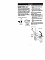
WARNING: This tdmmer is equipped with an internal combustion engine and should
not be used on or near any unimproved forest-covered, brush-covered or grasscovered land unless the engine's exhaust system is equipped with a spark arrester
meeting applicable local or state laws (if any). If a spark arrester is used, it should be
maintained in effective working order by the operator.
In the state of California the above is required by law (SecHon 4442 of the California
Public Resources Code). Other states may have similar laws. Federal laws apply on
federal lands. A spark arrester for the muffler is available through your nearest Sears
service center (See REPAIR PARTS section of this manual).
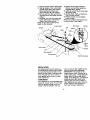
Theoperation
ofanytrimmer
canresultinforeign
objects
thrown
into
theeyes,whichcan result in severe eye damage. Always wear safety
glasses or eye shields while operating your tdmmer or performingany
adjustments or repairs. We recommend a wide vision safety mask
over spectacles or standard safety glasses.
I. GENERAL OPERATION
• Read, understand, and follow all
instructions on the machine and in the
manual before starting. Be thoroughly
familiar with the controls and the proper
use of the machine before starling.
• Do not put hands or feet near or under
rotating parts.
• Keep all parts of your body away from
muffler and spinning line. A hot muffler
can cause sedous bums.
• Only allow responsible individuals, who
are familiar with the instructions,to
operate the machine.
• Stay away from breakable objects, such
as house windows, auto glass, greenhouses, etc.
• Clear the area of objects such as rocks,
toys, wire, bones, sticks, etc., which
could be picked up and thrown by the
spinning lines.
• Be sure the area is clear of other
people before tdmming, particulady
small children and pets. Stop machine
if anyone enters the area.
• Wear appropriate clothing such as a
long-sleeved shirt or jacket. Also wear
long trousers or slacks. Do not wear
sheds.
• Do not wear loose clothing which could
get caught in this equipment.
• Do not operate the machine when
barefoot or wearing open sandals.
Always wear work gloves and sturdy
footwear. Leather work shoes or short
boots work well for most people. These
will protect the operator's ankles and
shins from small sticks, splinters, and
other debds, and improve traction.
• Do not pull machine backwards unless
absolutely necessary. Always look
down and behind before and while
moving backwards.
• Do not operate the machine without
proper guards, plates or other safety
protective devices in place.
• See manufacturer's instructionsfor
proper operation and installation of
accessories. Only use accessories
approved by the manufacturer.
• Never use blades, wire, or flailing
devices. This unit is designed for line
trimmer use only. Use of other accessories or attachments will increase the dsk
of injury.
• Stop the rotating trimmer head when
crossing gravel ddves, walks, or roads.
Wait for the cutting lines to stop rotating.
• Stop the engine (motor) whenever you
leave the equipment and allow it to
cool, before cleaning, repaidng or
inspecting the unit. Be sure the tdmmer
head and all moving parts have
stopped.
• Operate only in daylight or good
artificial light.
• Do not operate the machine while
under the influence of alcohol or drugs.
• Never operate machine in wet grass.
Always be sure of your footing: keep a
firm hold on the handle and walk; never
run.
• If the equipment shouldstart to vibrate
abnormally, stop the engine (motor)
and check immediately for the cause.
Vibration is generally a waming of
trouble.
• Always wear safety goggles or safety
glasses with side shields when operating machine.
3
II. SLOPEOPERATION
Slopes
area majorfactor related to slip
and fall accidents which can result in
severe injury, All slopes require extra
caution. If you feel uneasy on a slope, do
not tdm it.
DO:
• Tdm across the face of slopes: never up
and down. Exercise extreme caution
when changing direction on slopes.
• Remove obstacles such as rocks, tree
limbs, etc.
• Watch for holes, ruts, or bumps. Tall
grass can hide obstacles.
DO NOT:
• Do not tdm near drep-offs, ditches or
embankments. The operator could lose
footing or balance.
• Do not tdm excessively steep slopes.
• Do not trim on wet grass. Reduced
footing could cause slipping.
II1. CHILDREN
Tragic accidents can occur if the operator
is not alert to the presence of children.
Children are often attracted to the machine
and the tdmming activity. Never assume
that children will remain where you last
saw them.
• Keep children out of the trimming area
and under the watchful care of another
responsible adult.
• Be alert and turn machine off if children
enter the area.
• Before and while moving backwards,
look behind and down for small
children.
• Never allow children to operate the
machine.
• Use extra care when approaching blind
comers, shrubs, trees, or other objects
that may obscure vision.
IV. SERVICE
• Use extra care in handling gasoline
and other fuels. They are flammable
and vapors are explosive.
- Use only an approved container.
- Never remove gas cap or add fuel
with the engine running. Allow
engine to cool before refueling. Do
not smoke,
- Never refuel the machine indoors.
-
Never store the machine or fuel
container inside where there is an
open flame, such as a water heater.
- Move away from fueling site before
starting engine.
• Never run a machine inside a closed
area.
• Never make adjustments or repairs
with the engine (motor) running.
Disconnect the spark plug wire, and
keep the wire away from the plug to
prevent accidental starting.
• Keep nuts and bolts, especially trimmer
head and engine bolts, tight and keep
equipment in good condition.
• Never tamper with safety devices.
Check their proper operation regularly.
• Keep machine free of grass, leaves, or
other debds buildup. Clean oil or fuel
spillage. Allow machine to cool before
cleaning or storing.
• Stop and inspect the equipment if you
stdke an object. Repair, if necessary,
before restarting.
• Do not change the engine governor
setting or overspeed the engine.
• Clean and replace safety and instruction decals as necessary.
•,Look for this symbol to point out
important safety precautions. It means
CAUTION!!! BECOME ALERT!!! YOUR
SAFETY IS INVOLVED.
A WARNING: In order to prevent
accidental starting when setting up,
transporting, adjusting or making repairs,
always disconnect spark plug wire and
place wire where it cannot contact spark
plug.
A CAUTION: Muffier and other engine
parts become extremely hot dudng
operation and remain hot after engine
has stopped. To avoid severe burns on
contact, stay away from these areas.
Read
Ihase
les_a_-tJonsand_
manual in its
entiretybeforeyou attemptto assernbleor
operateyournew lrimmer.
IMPORTANT: Thistrimmerisshipped
WITHOUT OILOR GASOLINE inthe engine.
yournew ldmmerhas been assombledat tha
facto_ withthe exceptionofthase partsleft
unassembledfor shippingpurposes. Allparts
suchas nuts,washers,belts,etc., necessary
to completethe assemblyhavebeen placed
In the partshag. To ensuresafe and proper
obera_on nf yourtrimmer,all partsand
hardwareyou assemblemust be tightened
securely.Uso _e oonect toolsas necass_y
to ens,xe properUghfz_as.
Loose parts Packed Separately
20 OZ.
Bottle of oU
Tdmmer tJnes
(2)sets
(0.155 dlarnetsr
x 18,75 Inches long)
TO REMOVETRIMMER FROM CARTON
1. Remove loose parts included with
tdmmer.
2. Cut down two end comers of carton
and lay end panel down flat.
3. Remove all packing materials.
4. Roll trimmer out of carton and check
carton thoroughly for additional loose
parts.
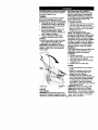
HOWTO SET UPYOURTRIMMER
TO UNFOLD HANDLE
IMPORTANT: Unfoldhandle carefulysoas
not to ptechor damagecoo'_olcables.
1. Loosen handle knob enough to allow
upper handle to be unfolded from the
shipping position.
2. Raise upper handle section into place
on lower handle and tighten handle
knob.
3. Remove handle padding holding
trimmer head control bar to upper
handle.
Your trimmer handle can be adjusted for
your trimmingcomfort. Refer to "ADJUST
HANDLE" in the Service and Adjustments
section of this manual.
Upper handle
Liftup
knob
handle
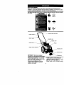
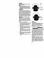
KNOW YOUR TRIMMER
READTHIS OWNER'S MANUAL AND SAFETY RULES BEFORE OPERATINGYOUR
TRIMMER, Compare the ilusb'ations withyourfdmmer to familiarizeyourselfwiththe location
of Verious controlsand a_ustments. Save thismaneaJforfuturereference,
"l_ese iymbo_
may appear on your trimmer or In IRma_m supplied with the product Learn and _
Omirmea_klg.
WARNING
Am nwn= m
&
0
CAUTION
ENGINE
OFF
FAST
SLOW
FUrcL
OIL
Trimmer head control bar
Sta_erhendle
Gasoline cap
Engine cover
Primer
Chassis cover
IMPORTANT: Thistrimmeris shipped
WITHOUT OIL OR GASOUNE in the engine.
Tdrnmer head control bar - must be held
down to _e ha_le to engnge bimmerhead.
Release to stopthe trimmerhead.
Pdmer- pumps additionalfuel fi'om
carburetorto the cylinderfor use when
startinga coldengine.
- Trimmer line
Throttle conb'ol - usedforstaringand
stoppingthe engine and allowsyouto select
eitherfast or slow en_ne speed.
Starter handle - usedforstartingthe engine.
Theoperation
ofanytdmmer
canresult
in
foreign objects being thrown into the
eyes, which can result in severe eye
damage. Always wear safety glasses or
eye shields while operating your trimmer
or performing any adjustments or repairs.
We recommend a wide vision safety mask
over spectacles or standard safety
glasses.
HOWTO USEYOURTRIMMER
ENGINE SPEED
The engine speed is controlled by a
throttie located on the side of the upper
handle. Fast position is for starting and
normal tdmming. Slow is for light trimming
and fuel economy. Stop is for stopping the
engine.
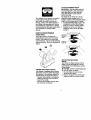
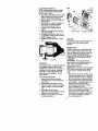
TO ADJUSTTRIMMING HEIGHT
ACAUTION:
Stop the engine and wati
for all moving parts to stop. Disconnect
spark plug wire from spark plug and
place wire where it cannot seine in
contact with plug.
The height of cut can be set to six (6)
different positions ranging from 1-1/2
inches to 3 inches. Recommended cutting
height for the average yard is 2 inches.
1. To adjust tdmming height, push in the
locking plate tab and move tdmmer
head up or down to desired position.
2. Release tab and be sure head is
locked into one of the six (6) height
positions.
Adjustable
Trimme
Head
Locking
Plate Tab
,,. @
l
Ij
II
TRIMMER HEAD DRIVE CONTROL
Yourtrimmer is equipped with a trimmer
head ddve control bar which will require
the operator to be positioned behind the
trimmer handle to operate the trimmer.
• Tdmmer head rotation is controlled by
holding the tdmmer head control bar
down to the handle.
• Trimmer head rotation will stop when
the control bar is released.
BEFORE STARTING ENGINE
ADD OIL
Yourb'imrneris shippedwithout oil in the
engine. For tyPe and grade of oilto use,
see "ENGINE" in the Maintenance section
of this manual.
A CAUTION: DO NOT overfillengine with
oil, or it will smoke on startup.
1. Be sure tdmmer is level and area
around oil fill is clean.
2. Remove oil dipstick from oil fill spout.
Make sure that rim of spout is clean.
3. Youreceive
a20oz.container
ofoil
withtheunit.Slowly
pour3/4(15oz,)
oftheoilfromthecontainer
downthe
oilfill spout into the engine.
4. Wait one minute to allow oil to settle.
Insert and tighten dipstick, then
remove it to check oil level.
5. Continue adding small amounts of oil
and rechecking the dipstick until it
reads full, DO NOT overfill, or engine
will smoke on startup.
6. Always be sure to retighten oil dipstick
before starting engine.
• Check oil
level
beforeeachuse.Add oilif
needed. Fil to UI line on dipsf_ck.
• Change the oilafterevery 25 hoursof
opere'&_nor each season. You may need
to change Ihe oil moreoften underdusty,
dirtyconditions.
ADD GASOUNE
• Fill
fuel
tank.Use fresh,
dean,regular
unleadedgasoine with a minimumof 87
octane. Do not mix oil with gasoline.
Purchasefuel in quantitiesthat can be
used within30 daysto assurefual
freshness.
_;iLWARNING: Expedence indicates that
alcohol blended fuels (called gasohol or
using ethanol or methanol) can attract
moisture which leads to separation and
formation of acids during storage. Acidic
gas can damage the fuel system of an
engine while in storage. To avoid engine
problems, the fuel system should be
emptied before storage of 30 days or
longer. Drain the gas tank, start the
engine and let it run until the fuel lines
and carburetor are empty. Use fresh fuel
next season, See Storage Instructionsfor
additional information. Never use engine
or carburetor cleaner products in the fuel
tank or permanent damage may occur.
A CAUTION: Fill to bottom of gas tank
filler neck. Do not overfill. Wipe offany
spilled oil or fuel. Do not store, spill or
use gasoline near an open flame.
Gasolinefillercap
Eng
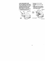
TO START ENGINE
1. To starta coldongiea, push_mer three
(3) flmes hefore lf_ing to start. Usea fin_
push. Thisstepis notusually necessary
when staring an engine whichhas
alreadyrun for a few minutes.
2. Move throttle con_oflevertotast position.
3. Hold upperhandlefirmlyand pul starter
handlequickly. Do notallow starterrope
to scap bask.
TO STOP ENGINE
• To stopengine, move throttlecontrollever
to step position.
NOTE: In eaoler weather it may be
necessary to repeat pdming steps. In
warmer weather overpdming may cause
flooding and engine will not start. If you
do flood engine, wait a few minutes
before attempting to start and do not
repeat priming steps, __1_/_
Throttle
\\ _"
Starter
handle_
TRIMMING TIPS
• Set the throttle control in the fast
position, If the weeds or grass are tall
and thick, operate the trimmer at a
slower walking speed.
• Frequently clean the undersideof the
tdmmer to remove any grass build up.
Keep top of engine around starter dear
and dean of grass clippings and chaff,
This will help engine air flow and extend
engine lIfe. See =TO REMOVE ENGINE
COVER" in the Maintenance section of
this manual.
• For best results and longer lasting line,
use the ends of the line to do the cutting.
This is easily done by moving slowly
through very thick and heavy weeds.
• Use the left side of tdmmer whan
tdmming along fences, walls, flowerbeds
and other such objects.
• If trimmer lioes heeame tea short,it will
take longerto complete the job. If
tdmmer linesare worn to less than half
their original length,they should be
replaced. See "TO REPLACE TRIMMER
LINE" in the Maintenance section of this
manual,
• Trimmer head contact with concrete,
asphalt or other hard surfaces may
cause premature wear of the ball on .
bottom of trimmer head.
aESOP,,
SEnV,CE
IT
=R
Check for Loo_e Fasteners
;.'
_
iClean Tdmmer
DATES
'ISERVIOE
(I/
I¢
#
lb
#
I
M
clean Under Engine Cover
I_z
Ik/
E_ Check drive belt/pulleys
R
|
Check/Replace Tdmmer Lines
I1_:_
Check Engine Oil Level
I_
Change
Engine
Clean Air
Filter Oil
_1_/t
I_ ,2
2
Inspect Muffler
VS
N! cl..n o_nepl*o_
Spark
Plug
Replace Air Filter Paper Cartridge
V'
le/=
1 - Change n,_ e of_m when opetatlngundm a heew k:_d o=-in high acnblefltte_.
2 - Servic6 m_e ol_n v_
op_
in dirtyor dusty ¢_lilions,
3 - I_epla_ _
lines when they have _
_ot_lf their original length,
GENERAL RECOMMENDATIONS
The warranty on this trimmer does not
cover items that have been subjected to
operator abuse or negligence. To receive
full value from the warranty, operator must
maintain trimmer as instructed in this
manual.
Some adjustments will need to be made
periodicallyto propedy maintain your unit.
AU adjustments in the Service and
Adjustments section of this manual should
be checked at least once each season.
• Once a year, replace the spark plug
and replace air filter element. A new
spark plug and clean/new air filter
element assures proper air-fuel mixture
and helps your engine run better and
last longer.
• Follow the maintenance schedule in
this manual,
BEFORE EACH USE
1. Check engine oil level,
2. Check for loose fasteners.
3. Clean under engine cover.
LUBRICATION
To prolong the useful life of your trimmer,
change engine oil as recommended in
this section of Owner's Manual.
IMPORTANT: Do notolorgreaseplas_c
wheel beanngs.Vkcous lubricantsw=]la_act
dustand dirtthatwil sbertenthe lifeof the
self-lubricating bearings.If _u _ theymust
be It_0dcated,use onlya dry,pewdered
graphite type lubricantsparingly.
PRODUCT SPECIFICATIONS
Serial No.
Date of Purchase:
Gasoline "l_pe:
Gasoline Capacity:
OII lype:
(API-SF-SJ)
Unleaded Regular
1.25 Quarts
SAE 30 (Above 32° F)
SAE 5W-30 (Below 32_F)
Oil Capacity:
Spad_ Plug :
l_mmer
20 Ozs.
Champion RJ19LM4
(Gap: .045")
Une Diameter:
.155 inch
Trimmer Une Length:
18.75 inches
The model and sedal numbers will be found on
a decal attached to the rear of the trimmer.
Record both serial number and date of
purchase in space provided above,
TRIMMER
Alwaysobserve safety ruleswhen performing any maintenano_.
TIRES
• Keep tires
fleeof gasolne, oil,or insect
cunlmlchemicals
whichcan harm rubber.
• Avoidstumps,stcues,dcep ruts,sharp
objectsand o_er hazardsthat may cause
tiredamege.
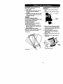
TRIMMERUNE
For best results, replace trimmer lines
when they have worn to half their odginal
length. Use .155 inch diameter tdmmer
line. Cut new tdmmer line length to 18-3/4
inches. After new line is installed on
trimmer head, check all lines so they do
not vary more then one (1) inch in length.
This is important to make sure the trimmer
head is balanced and will not vibrate
abnormally.
AWARNING: Use only the specified
trimmer line. Do not use other matedals
such as wire, string, rope, etc. Wire can
break off during tdmming and become a
dangerous missile that can cause serious
injury.
TO REPLACE TRIMMER LINE
1. Disconnect spark plug wire from spark
plug and place wire where it cannot
come in contact with spark plug.
2. Remove worn trimmer line from line
carrier plate.
3. Fold new, cut to length, trimmer line in
half and insert folded end through
carder plate opening to back side of
retainer clip.
4. With folded end of line at back side of
retainer clip, pull line outward until
line is fully seated under the retainer
clip.
5. Repeat on other side of carder plate.
6. Check all lines to be sure they are the
same length.
7. Reconnect spark plug wire to spark
plug.
Trimmer
line
Carrier plate
opening
clip
ENGINE
LUBRICATION
Use only high quality detergent oil rated
with API sen/ice classification SF-SJ.
Select the oirs SAE viscosity grade
according to your expected operating
temperature.
SAE VISCOSITY
GRADES
NOTE: Although multi-viscesity oils
(5W30, 10W30 etc.) improve starting in
cold weather, these multi-viscosity oils
will result in increased oil consumption
when used above 32°F. Check your
engine oil level more frequently to avoid
possible engine damage from running
low on oil.
Change the oil after every 25 hours of
operation or at least once a year if the
unit is not used for 25 hours in one year.
Check the crankcase oil level before
starting the engine and after each five (5)
hours of continuous use. Tighten oil plug
securely each time you check the oil
level.
10
TOCHANGE
ENGINE
OIL
NOTE:Before
tipping
trimmer
todrain
oil,drainfueltankbyrunning
engine
untilfueltankisempty.
1. Disconnect
sparkplugwirefromspark
plugandplacewirewhere
it cannot
comeincontact with spark plug.
2. Remove engine oil cap; lay aside on a
clean surface.
3, Tip trimmer on its side as shown and
drain oil into a suitable container,
Rock trimmer back and forth to
remove any oil trapped inside of
engine.
4, Wipe off any spilled oil from tdmmer
and side of engine.
5, Fill engine with oil (See "ADD OIL" in
the Operation section of this manual),
6. Replace engine oil cap,
7. Reconnect spark plug wire to spark
p(ug.
AIR FILTER
Your engine wiU not run properly and may
be damaged by using a dirty air tilter.
Replace the air filter every 100 hours of
operation or every season, whichever
occurs first. Service air cleaner more
often under dusty conditions. Do not
wash air filter,
TO CHANGE AIR FILTER
1. Remove the air filter by tuming
clockwise to the stop and pull away
from collar.
2. Remove filter from inside of cover.
3. Clean the inside of the cover and the
collar to remove any dirt accumulation.
4, Insert new filter into cover,
5, Put air filter cover and filter into collar
aligning the tab with the slot.
6, Push in on cover and turn counterclockwise to tighten.
Collar
i
Turn
clockwise
to
_
Clip
Slot
Air filter
Air filter cover
Turn
counterclockwise to tighten
MUFFLER
Inspect and replace corroded muffler as
it could create a fire hazard and/or
damage.
SPARK PLUG
Replace spark plugs at the beginning of
each mowing season or after every 1013
hours of operation, whichever occurs first.
Spark plug type and gap setting are
shown in =PRODUCT SPECIFICATIONS"
in Maintenance section of this manual.
CLEANING
IMPORTANT: For best performance,
keep tdmmer free of built-upgrass and
trash. Clean the underside of your
tdmmer after each use.
ACAUTION:
Disconnect spark plug wire
from spark plug and place wire where it
cannot come in contact with the spark
plug.
• Turn trimmer on its side. Make sure air
filter and carburetor are up. Clean the
underside of your trimmer by scraping
to remove build-up of grass and trash.
• Clean engine often to keep trash from
accumulating. A clogged engine runs
hotter and shortens engine life.
• Keep finished surfaces and wheels
free of all gasoline, oil, etc.
• We do not recommend using a garden
hose to clean trimmer unless the
electdcal system, muffler, air filter and
carburetor are covered to keep water
out. Water in engine can result in
shortened engine life.
11
CLEAN UNDER ENGINE COVER
Clean under engine cover before each
use, or more frequently in heavy cutting
or dirty conditions. Engine cover screen
and engine air intake screen must be
kept free of dirt and chaff to prevent
engine damage from overheating.
Be sure engine is cool before cleaning.
1, Unscrew knob on top of cover.
2. Lift cover up and away from engine.
3. Clean cover and cover screen
thoroughly.
4. Clean top of engine and air intake
screen.
5. Replace engine cover and tighten
knob securely. Be sure the front tabs
of engine cover are located in the
slots in engine housing.
Threaded
Knob
Engine_
screen
cover -Starter
rope
_
Air intakescreen
Housing slots
12
CAUTION: Before performing any
service and adjustments:
1. Stop engine.
2. Make sure the rotating lines and all
moving parts have completely
stopped.
3. Disconnect spark plug wire from spark
plug and place where it cannot come
in contact with plug.
TO REMOVE/REPLACE TRIMMER HEAD
DRIVE BELT
1, Remove screw at front of chassis
cover.
2. Lift cover up and away from tdmmer.
TRIMMER
TO ADJUSTTRIMMING HEIGHT
See "TO ADJUSTTRIMMING HEIGHT"in the
OperalJon
section
otW_ manual.
TO ADJUST HANDLE
The upper handle may be adjusted to
different height positions.
• Loosen handle knob only enough to
allow the upper handle to pivot to the
desired position.
• Tighten handle knob securely.
NOTE: The handle knob and bolt may be
reversed for left handed operation.
Upper han_e
Chassis
3. Remove the two (2) screws on sides
of trimmer secudng the debris shield.
4. Turn trimmer on its side with carburetor and fuel cap up.
5. Remove the two (2) screws on
underside of trimmer secudng the
debds shield.
6. Slide the debris shield rearward and
remove.
7. Remove belt from engine pulley on
crankshaft.
pulley
Debris shield screws
Han_e knob
13
8. Remove belt from trimmer head pulley.
9. Note the position of the control cable
and idler retum spdng, then remove
idler assembly from chassis and
remove belt and idler from trimmer.
10. Remove belt from idler assembly by
removing bottom belt keeper and idler
pulleys.
11.Assemble new belt, idler pulleys and
bottom belt keeper to idler bracket.
Tighten pulley bolts securely.
NOTE: Be sure belt is inside top belt
keeper on idler assembly.
12. Position belt and idler assembly in
trimmer, reconnect idler spring and
assemble idler to chassis.
13.Install belt around trimmer head pulley
and engine pulley.
14.Replace debds shield and tighten the
four (4) screws securely.
15. Replace chassis cover and tighten
screw securely.
Always use Craftsman replacement parts
to assure proper fit and long llfe.
idler bracket
Flat idler
BoSom
'_
Ldler assembly
Top belt keeper
.._
belt
keeper
'_-._ t
Bolt
ENGINE
_
Trimmer head pulley
SPEED
Your engine speed has been factory set.
Do not attempt to increase engine speed
or it may result in personal injury. If you
believe that the engine is running too fast
or too slow, take your unit to a Sears or
other qualified service center for repair
and/or adjustment.
CARBURETOR
Your carburetor has a nonadjustable fixed
main jet for mixture control. If your engine
does not operate propedy due to suspectad carburetor problems, take your
unit to a Sears of other qualified service
center for repair and/or adjustment.
IMPORTANT: Never tamper with the
engine governor, which is factory set for
proper engine speed. Overspeeding the
engine above the factory high speed
setting can be dangerous. If you think the
engine-governed high speed needs
adjusting, take your unit to a Sears or
other qualified service center, which has
proper equipment and experience to
make any necessary adjustments.
14
Immediatelyprepareyear bimmerfor storage
at the endof the seaean er ifthe unitwtllnot
be usedfor 30 daysor more.
TRIMMER
When 5_mmeris to be storedfora periodof
time,dean it thoroughly,removeall dirt,
grease, leaves,etc. Storein a dean, dryarea.
1. Clean entre ldmrnar(See "CLEANING" in
the Maintenancesectionof thismanual).
2. Lutxicateas shownin _ Maintenance
secifon of _s rnanuai.
3. Be sure thatall nots, bolts,serews,and
p_nsare securelyfastened. Inspect
movingpartsfor damage, breakage and
wear. Replace if necessary.
4. Teach up all rustedor chippedpaint
surfaces;sand lightlybeforepaining.
HANDLE
Youcan fold yourb'immerhandlefor storage.
• L_:<_sen
handle knob enough to alow
upperhandleto be folded forward.
IMPORTANT: V_nenfolding the handlefor
stcmge or b'easpertatJon,
he sure to foldthe
handleas shown eryoun_y damage the
control
cables.
tank dudngstorage.Also, experience
indicatesthat alcohol blendedfuels (called
gasuhelor usingethanolor methanol)can
attractmoisturewhichleads to separalton
and formation of adds duringstorage.Acidic
gas _ damagethe fuel systemof an
engine while in storage.
1. Drain the fuel tank.
2. Start the engine and let it run until the
fuel lines and carburetor are empty.
• Never use engine or carburetor cleaner
productsin the fuel tank or permanent
damage may occur.
• Use fresh fuel next season.
NOTE: Fuel stabilizeris an accaptaUe
aitemativein minin_ng the formationof fuel
gum depositsduringstorage. Add stabiizer
to gasolinein fueltankor storagecontainer.
Alwaysfollowthe mix ra{_ofoundon stabgizer
ceatainer. Run engine at least10 minutes
after addi'K
3 stabilizerto allowthe stabilizerto
reachthe carburetor. Do not drainthe gas
tank and carburetor if usingfuel stabilizer.
ENGINEOL
Drab oil (withengine warm) and replacewith
cleanengineoil. (See"ENGINE" le the
Maintenancesectionof thismanual).
CYUNDER
1. Remove spark plug.
2. Pour one ounce (29 ml) of oil through
spark plug hole into cylinder.
3. Pull starter handle slowly a few times
to distribute oil.
4. Replace with new spark plug.
OTHER
• Do notstere gasolinefromone seasonto
another.
• Replaceyear gasoline can if year can
startsto rusL Rust and/or did in your
gasolinewill cause problems.
• If possble, storeyourunitindoorsand
covorit to givepretecltonfrom dustand did.
• Cover year unitwith a suitableprotective
coverthatdoes not retainmoisture. Do
notuse plaslJc.Plasticcannotbreathe,
whichalows condensationto form andwill
causeyourunitto mst.
Handle knob
IMPORTANT: Nevercovertrimmerwhile
engine and exhaustareas are stillwarm.
ENGINE
• I=CAUTION: Never store the trimmer
FUELSYSTEM
with gasoline in the tank inside a building
IMPORTANT: It isimp<xtantte preventgum
where fumes may reach an open flame or
depositsfromformingin essentialfuel system spark. Allow the engine to cool before
parts such as carburetor, fuel filter,fuel hoseor15 storing in any enclosure.
handle
TROUBLESHOOTING
PROBLEM
Doesnotstart
CAUSE
CORRECTION
1, Dirtyairfilter.
2. Out of fuel.
3. Stale fuel.
4. Water in fuel.
5. Spark plug wire is
disconnected.
6. Bad spark plug.
7. Throttle control lever not
in correct position
(if equipped).
1. Clean/replace air filter.
2. Fill fuel tank.
3. Drain tank and refill with
_esh clean fuel.
4. Drain fuel tank and
carburetor and refill tank
with fresh gasoline.
5. Connect wire to plug.
6. Replace spark plug.
7, Move throttle lever to FAST
position.
Loss of power
1. Dirty air filter.
2. Buildup of grass, leaves,
and trash under trimmer.
3. Too much oil in engine,
4. Walking speed too fast.
1. Clean/replace air filter.
2. Clean underside of trimmer
and trimmer head.
3. Check oil level.
4. Trim at slower walking
speed.
Excessive
Vibration
1. Lines uneven or broken.
2. Loose nuts or bolts.
1. Check trimmer lines.
2, Check all hardware,
including engine bolts.
3. Check/repair tdmmer head.
3. Damaged trimmer head.
Starter rope hare
topull
1. Bent engine crankshaft.
1. Contact a Sears or other
qualified service center.
Loss of head
drive
1. Belt not driving.
1. Put belt on pulleys or
replace belt if broken,
Hard to push
1. Handle height position not
right for you.
1. Adjust handle height
to suit.
1. Trimmer line length is
too short.
1. If line is worn or broken to
half original length,
replace line.
2. Move throttle lever to FAST
position.
Poor trimming
j performance
2. Throttle control lever not
in correct position
(if equipped).
Trimmer head
does not
retain line
1. Trimmer line not
propedy installed.
2. Broken line retainer clip.
3. Incorrect size of
trimmer line.
16
1. Follow instructions in
Maintenance section.
2. Replace string carder plate
assembly.
3. Use ,155 diameter
trimmer line.
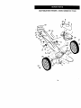
CRAFTSMAN WEED TRIMMER--
MODEL NUMBER 917.773423
18
1
11
26
27
14
27
25
34
CRAFTSMAN WEED TRIMMER- - MODEL NUMBER 917.773423
KEY
NO.
PART
NO.
1
---
2
3
4
5
6
7
8
9
f(}
11
12
13
14
15
16
17
18
19
20
21
22
23
24
25
26
27
28
29
30
34
35
150406
169791
STD502582
177622.
174274
174030
169821)(479
150076
t69797X479
170980
136376
170681
170682
170554
15363_
132004
66426
176983
174934
158755
178700X004
150078
52160
57143
752063
83923
176999
174034
174038
86899X004
750634
178779
AvollabLeaccessories
"/t33623
7133600
7t 7_gt
DESCRIP11ON
Engine, Craft=man,
Modol Number 143.015502
(See BreakdOWn)
Bolt, Engine Mounting 3/8-16
Pulley, Engine (Lndudes Setscrew, Key #4)
Setscrew, Pulley
Cover, EngJr-,e,with Screen
Kr!ob, Engine Cover
StUd, Engine Cover
Handle, Lower
Screw, Hex Washer Head 5/16-18 x ,75
Handle, Upper
Bolt, Handle
Kr_ob,Handle
Acljuster, Handle, Inside
Adjuster, Handle, Outolde
Spdng, Handle Adjust
Guide, Rope
Locknut 1/4 x 20
WIreTire
Control Bar
Throttle Control
Screw, Hex Washer Head
Axle Shaft Assembly
Screw, Hex Washer Head 5/16-18 X .75
Washer, Axle
Washer, Wave
Wheel, 14 x 2
Hex Flange Locknut 3/8-16
DrtveCable
Decal,Warning
Decal, Engine Cover
Bracket, Upstop
Screw, Thd. Roll. #10-24 x 5/8
Owner's Manuol, EngJLsh/SpanLsh
not included with trimmer:
Gas Can (2.5 gal.)
SAE 30W OII (20 oz.)
TSmmer Ltne (Pack of 24 s_ngs, .155 dia._
NOTE: All component dimensions given in U.S. inches
1 Inch = 25.4 rnrn
35
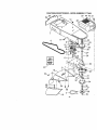
CRAFTSMAN WEED TRIMMER-- MODEL NUMBER917.773423
20
14
4
44
47 21
43
17
23
24
13
r
0_31
27
32
5O
36
CRAFTSMAN WEED TRIMMER-- MODEL NUMBER 917.773423
KEY
NO.
1
2
3
4
5
6
7
8
9
10
11
12
13
14
15
16
17
18
19
2O
21
22
23
24
25
26
27
28
29
3O
PART
NO.
174031X558
169802
173715
169790
172145X004
166042
173716
751592
166043
160829
155552
173717
174719
145212
173811
177811
57808
85768
175301
170553
149746
STD541137
STD561137
$10551037
169792
172551
174549
172520
169766X479
174543
31
32
33
34
36
37
38
39
4O
174581
176973
172519
174544
172516
174580
172523
172636
172342
41
43
44
45
46
47
48
49
50
61
52
174029
174042
174035
174596X479
17060408
174036
52784
76399
59931
177972
178848
DESCRIP'nON
Chassis Assernbly
Line, Trimmer. 155 diameter x 18.75 Io_g
Screw, Self-Tapping 5/16-18 x 1
V-Bert
Bracket, Idler
Pulley, idler, V-Groove
Bolt, Hex Head 318-16 x 1.25
Lock,nut, Hex 3/8-16
Pulley, Idler, Rat
Bolt, Shctllder
Locknut 5/16-18
Spacer
Boit, Shoulder
Locknut, Flange
Spring, Return
Shield, Debds
Screw 114-20 x 112
Screw #10-24 x 3/4
Skirt
Cover, Chassis, Top
Screw #10-24 x 1-314
Nut 3/8-24 UNF
Washer, Lock 3/8
Washer, Flat 318
Pulley, Driven
Spacer, Pulley
Be_deg
Jackshafl
Cover, Chassis, Bottom
Splndle Housing Assembly
(* Includes Upper Bearing, Key #27)
Ring, RatainLng, External, 17ram
Spring, Locldng Plate
Locking Plate
Carrier Plate Assembly
Cover, Bearing
Ring, Retaining, Internal, 40ram
MowBall
Bolt, MOWBall
Head Assembiy, CompLete
(InCkldeS Key Numbers 22-28, 30-39)
Spacer
Decal, Instruction
Decal, Chassis Cover
Bert Keeper, Bottom
Screw, Sed-Tapping
Decal, Instruction
Washer
Screw
Lock,nut
Skid
Screw #10-16 x 5/8
NOTE: All component dimensions given in U.S. inches
1 inch = 25.4 mm
37
CRAFTSMAN 4-CYCLE ENGINE
MODELNUMBER143.015502
40O
135
130
120
119
416
125
46
309A
311A
185
38
,
CRAFTSMAN 4-CYCLE ENGINE
KEY PART
NO. 140.
1
2
6
7
12
12A
12B
14
15
16
17
18
19
_0
30
40
41
42
37266
26727
33734
36557
36775
36558
36694
25277
30589
34839A
31335
651018
37329
32_0
37459
40027
40_8
4(X_5
480_6
43
45
46
48
50
48006
4O807
2O381
36777
32610A
27241
37460
52
69
76
29914
37609
37808
72
75
80
81
82
83
86
89
80
37614
27897
30574A
305_0A
30591
30588A
650486
610961
611213
650815
650816
34443C
610118
651807
37480
37574
36787
36_5
37286
37289
80_1A
37596
31672
31673
48017
93
100
101
103
104
110
119
120
126
126
130
135
160
151
151A
MODEL NUMBER143.015502
DESCRIPI_N
Cylinder (Incl. 2120 _ 150)
DowelPin
Breather Element
Breather Ass'y, (Ir_, 6 & 12A)
BreatherTube
Breether Cover&Tube (IncL 12B)
Breather Tuha Elpew
Washer
Govemor Rod (taol. 14)
Governor Lever
Governor Lever Clamp
Screw, T-16, 8-32 x 19/64"
Governor Spdng
Oil Seal
Crankshaft
Piston, Pin & Ring Set (Std.)
Piston, Pltl & Ring Set(.010"OS)
Piston & PipAssy.(Std.)(Ir, cl.43)
Piston & Pin Ass'y. (.010" OS)
(Includes Key Number 43)
Ring Set (Std.)
Ring Set (.010" OS)
PLntonPIr_ Retaining Ring
Connecting Rod Assy. (Incl. 46)
Cormentiilg Rod Bolt
Valve Lifter
Camshaft (Exhaust MCR)
(Includes Key Number 104)
Oil Pump Ass'y.
• MounSng Flange Gasket
Mounltng Flange
(Includes Key #72-83,306)
Ql_Drain Plug
Oil Seat
Governor Shaft
Washer
Governor Gear Ass'y. (Incl, 61)
Governor Speol
Screw, 114-20 x 1-114"
Flywheel Key
Rywheel
SellevilLeWasher
Flywhael Nut
Solid State Ignition
Spark Ping Cover
Screw, T-15, 16-24 x 16116*
Cam Bushing
Ground Wire
• Cylinder Head Gasket
Cy6nder Head
Exhaust Valve (Std,) (Incl. 151)
Intake Valve (9td.) (Incl, 151
Screw, 5/16-18 X 1-1/2"
Resietor Spark Plug (RJ 19LM4)
Valve Spring
Valve Spring Cap
Ir_ake Valve Seal
_'Y
NO.
PART
NO.
169
172
174
178
179
182
184
185
186
200
206
207
209
223
224
238
239
241
245
250
260
261
262
275
277
285
287
296
292
298
300
301
306
306
307
309
309A
310
311A
313
370A
370C
380
390
406
36783
36784
30200
29752
30593
6201
26756
36785
36255
37134
610973
36280S
80200
650451
36786
650932
34338
36919
36805
37122
36980
30280
650831
36790A
650988
35287A
650926
34357
26466
28763
35686
36246
35577
37616
35499
650562
650783
35576
37611
34080
36261
37316
640262
580763
37613
416
36086
417
900
650821
780837B
-- -----
DESCRIPTION
* Gasket, Valve Cover
Valve Cover
Screw, 16-24 x 9/16"
Nut & Lock Washer, 114-26
Retolner Clip
Screw, 1/4-28 x 718"
* Gasket, Carburetor-Intake Pipa
Intake Pipe
Govemor Link
Control Bracket (Incl. 206)
Terrnina_
Throftle Link
Screw, 10-24 x 9/16"
Screw, 1/4-20 x 1"
* Intake Pipe Gasket
Screw, 10-32 x 49/64"
* Air Cleaner Gasket
AirCleanerCollar
Air Cleaner Filter
Air Cleaner Cover
BLowerHousing
Screw, 10-24 x 9/16"
Screw, 1/4-20 x 112"
Muffler
Screw, 1/4-26 x 2-9132"
Starter Cup
Screw, 8-32 x 21164"
FuelLIne
Fuel Line Clamp
Screw, 10-32 x 35/64"
Fuel Tank (Incl. 292 & 301)
Fuel Cap
Oil FilITube
* "O'-RJng
"O'-PJng
Screw, 10-32 x 3/8"
Screw, 10-24 x 314"
Dipstick
Holdt3own Bracket
Spacer
LubdCalton Decol
Primer Oecol (3X)
Carburetor (Incl. 184
Rewind Starter
Gasket Set
(Includes oil Items M_rked *)
Spark Arrestor Kit
(includes Key # 417) (Opltonal)
Screw, 10-32 x 1/2" (Op_onal)
Replacement Short BLock
750837B, order ftom71-999
RPM High 3450 to 3750
RPM Low 2000 to 2300
NOTE: All component dimensions given LnU.S. inches
1 inch = 26,4 mm
39
CRAFTSMAN 4-CYCLE ENGINE
MODELNUMBER143,015502
NO,
PART
NO.
DESCIRIP'i_ON
-1
2
4
5
6
7
16
17
18
20
20A
25
27
28
29
30
31
35
36
36A
37
40
44
47
48
60
640262
631615
631767
631184
631183
640070
656506
631807
651025
630766
640018
640200
631867
631024
632019
631028
631021
631022
64(_59
640080
632766
632547
640175
27110A
630748
631027
632760B
Carburetor (Incl. 184 ot Engine Parts List)
Throt0e Shaft & Lever Assembly
Throttle Return Spring
Duat Seal Washer
Duat Seal (Throttle)
Throttle Shutter
Shutter Screw
Fuel Fitting
Throttle Crack Screw/Idle Speed Screw
Tension Spdng
Idle Restrictor Screw
Idle Restdctor Scrwe Cap (Black)
Float Bowl
Float Shaft
Float
Float Bowl"O" Ring
Inlet Needle, Seat, & Clip (IncL.31)
SpdngCllp
Pdmer Bulb/Ratainer Ring
Main Nozzle Tube
Ca_urator Tube
"0" Ring, Main Nozzle Tube
High Speed Bowl Nut
BowlNut Washer
Welch Plug, Idle Miature Well
Welch Plug, Atmospheric Veat
Repair kit (Incl, Items Marked *)
•
•
•
•
•
•
*
•
•
•
•
4O
CRAFTSMAN 4-CYCLE ENGINE
MODELNUMBER143.015502
I
\
12
/
13
KEY PART
NO, NO,
DESCRIPllON
---1
2
3
4
5
6
7
8
11
12
13
Rewind Starter
Spdng Pin (Incl. 4)
Washer
Retainer
Washer
Brake Spring
Starter Dog
Dog Spring
Pulley & Rewind Spring Ass'y.
Starter Housing Ass'y.
Starter Rope (Length 98" x 9164" dla.)
Starter Handle
590763
590599A
590600
590696
590601
590697
590698
590699
590700
590764
590535
590701
41
For repairofmajorbrand appliances in your own home...
no matter who made it, no matter whosold
1-8OO-4-MY-HOME e
(1_)
A_n_ dayorr_t
(u.s._and_)
For repair of carry-in products likevacuums, lawn equipment, and
electronics,
caUforthe nearest Sears Parts and Repair Center.
1-800-488-1222
,,_tane,dayornig_(U.S.A.
rely)
W1NwJJear_coltl
Forthe replacementparts, accessoriesand owner'smanuals
that you need to do-it-yourself,callSears PartsDIrect_]
1-800-366-PART
(1-800-366-7278)
6 a.m.- 11p_n., 7days aweek
(U.S.A._Ny)
_ww_ears.com_artsdrect
To purchase or inquire about a Sears Service Agreement
or Sears MaintenanceAgreement:
1-800-827-6655 (u.s.A)
1-800-361-6665 (Canada)
7 a.m.- 5 p.m.,CST, Mort.- Sat
9 a.m.-8 p.m.EST, M - F, 4 p.m. Sat.
® Registered Trademark I TM Trademark I s_ Service Mark of Seam, Roebuck and Co.
® Marca Registrada / TMMarca de Fabrica / s_ Marca de Servicio de Sears, Roebuck and Co.
MCMarque de commerce / _o Marque d_posde de Sears, Roebuck and Co.
178779 02.22.01 BY
Printed in U.S.A.