1
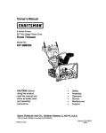
Owner's Manual
ICRnFTSMnN+I
6.0 HORSEPOWER
22 INCH CUT
WHEELED
WEEDTRIMMER
Model No.
917.773701
•
•
•
•
Safety
Assembly
Operation
Maintenance
•
•
Espa_ol
Repair Parts
,_CAUTION:
Read and follow all
Safety Rules and Instructions
before operating this equipment.
Sears, Roebuck and Co., Hoffman Estates, IL 60179
Visit our Craftsman website,, www.sears.com/craftsman
Warranty .................................................
Safety Rules ...........................................
Assembly ................................................
Operation ................................................
Maintenance Schedule ..........................
Maintenance ...........................................
2
2
5
6
9
9
Product Specifications............................ 9
Service and Adjustments...................... 12
Storage ................................................. 14
Troubleshooting ................................... 15
Repair Parts .......................................... 30
Parts Ordering ........................ Back Cover
LIMITED TWO YEAR WARRANTY ON CRAFTSMAN WEEDTRIMMER
For two years from date of purchase, when this Craftsman Weedtdmmer is maintained,
lubdcated, and tuned up according to the operating and maintenance instructions in
the owner's manual, Sears will repair free of charge any defect in matedal or workmanship.
If this Craftsman Weedtrimmer is used for commercial or rental purposes, this warranty
applies for only 90 days from the date of purchase.
This Warranty does not cover:
• Expendable items which become worn dudng normal use, such as rotating lines,
belts, air cleaners and spark plug.
• Repairs necessary because of operator abuse or negligence, including bent
crankshafts and the failure to maintain the equipment according to the instructions
contained in the owner's manual.
Warranty service is available by returning the Craftsman Weedtdmmer to the nearest
Sears Service Center in the United States. This warranty applies only while this product
is in use in the United States.
This Warranty gives you specific legal dghts, and you may also have other dghts which
vary from state to state.
Sears, Roebuck and Co., Dept. 817 WA, Hoffman Estates, IL 60179
WARNING: This tdmmer is equipped with an internal combustion engine and should
not be used on or near any unimproved forest-covered, brush-covered or grasscovered land unless the engine's exhaust system is equipped with a spark an'ester
meeting applicable local or state laws (if any). If a spark arrester is used, it should be
maintained in effective working order by the operator.
In the state of California the above is required by law (Section 4442 of the Califomia
Public Resources Code). Other states may have similar laws. Federal laws apply on
federal lands. A spark arrester for the muffler is available through your nearest Sears
service center (see the REPAIR PARTS section of this manual).
2
Theoperation
ofanytrimmer
canresult
inforeign
objects
beingthrown
intotheeyes,whichcan result in severe eye damage. Always wear
safety glasses or eye shields while operating your trimmer or performing any adjustments or repairs. We recommend a wide vision safety
mask over spectacles or standard safety glasses,
I. GENERAL OPERATION
• Read, understand, and follow all
instructionson the machine and in the
manual before starting. Be thoroughly
familiar with the controls and the proper
use of the machine before starling.
• Do not put hands or feet near or under
rotating parts.
• Keep all parts of your body away from
muffler and spinning line. A hot muffler
can cause serious bums.
• Only allow responsible individuals, who
are familiar with the instructions,to
operate the machine.
• Stay away from breakable objects, such
as house windows, auto glass, greenhouses, etc.
• Clear the area of objects such as recks,
toys, wire, bones, sticks, etc., which
could be picked up end thrown by the
spinning lines.
• Be sure the area is clear of other
people before tdmming, perticulady
small children and pets. Stop machine
if anyone enters the area.
• Wear appropriate clothing such as a
Iong-sleevad shirt or jacket. Also wear
long trousers or slacks. Do not wear
shorts.
• Do not wear loose clothing which could
get caught in this equipment.
• Do not operate the machine when
barefoot or wearing open sandals.
Always wear work gloves and sturdy
footwear. Leather work shoes or short
boots work well for most people. These
will protect the operator's ankles and
shins from small sticks, splinters, and
other debris, and improve traction.
• Do not pull machine backwards unless
absolutely necessary. Always look
down and behind before and while
moving backwards.
• Do not operate the machine without
proper guards, plates or other safety
protective devices in place.
• See manufacturer's instructionsfor
proper operation and installationof
accessories. Only use accessories
approved by the manufacturer.
• Never use blades, wire, or flailing
devices. This unit is designed for line
trimmer use only. Use of other accessories or attachments will increase the dsk
of injury.
• Stop the rotating trimmer head when
crossing gravel drives, walks, or roads.
Wait for the cutting lines to stop rotating.
• Stop the engine (motor) whenever you
leave the equipment and allow it to
cool, before cleaning, repairing or
inspecting the unit. Be sure the trimmer
head and all moving parts have
stopped.
• Operate only in daylight or good
artificial light.
• Do not operate the machine while
under the influence of alcohol or drugs.
• Never operate machine in wet grass.
Always be sure of your footing: keep a
firm hold on the handle and walk; never
rua.
• If the equipment should start to vibrate
abnormally, stop the engine (motor)
and check immediately for the cause.
Vibration is generally a waming of
trouble.
• Always wear safety goggles or safety
glasses with side shields when operating machine.
II. SLOPEOPERATION
Slopes
area majorfactorrelated
toslip
andfallaccidents
whichcanresultin
severe
injury.Allslopes
require
extra
caution. If you fool uneasy on a slope, do
not tdm it.
DO:
• Tdm across the face of slopes: never up
and down. Exercise extreme caution
when changing direction on slopes.
• Remove obstacles such as rocks, tree
limbs, etc.
• Watch for holes, ruts, or bumps. Tall
grass can hide obstacles.
DO NOT:
• Do not trim near drop-offs, ditches or
embankments. The operator could lose
footing or balance.
• Do not tdm excessively steep slopes.
• Do not trim on wet grass. Reduced
footing could cause slipping.
II1. CHILDREN
Tragic accidents can occur if the operator
is not alert to the presence of children.
Children are often attracted to the machine
and the tdmming activity. Never assume
that children will remain where you last
saw them.
• Keep children out of the tdmming area
and under the watchful care of another
responsible adult.
• Be alert and turn machine off if children
enter the area.
• Before and while moving backwards,
look behind and down for small
children.
• Never allow children to operate the
machine.
• Use extra care when approaching blind
comers, shrubs, trees, or other objects
that may obscure vision.
IV. SERVICE
• Use extra care in handling gasoline
and other fuels. They are flammable
and vapors are explosive.
- Use only an approved container.
- Never remove gas cap or add fuel
with the engine running. Allow
engine to cool before refueling. Do
not smoke.
- Never refuel the machine indoors.
- Never store the machine or fuel
container inside where there is an
open flame, such as a water heater.
-
Move away from fueling site before
starting engine.
• Never run a machine inside a closed
area.
• Never make adjustments or repairs
with the engine (motor) running.
Disconnect the spark plug wire, and
keep the wire away from the plug to
prevent accidental starting.
• Keep nuts and belts, especially trimmer
head and engine bolts, tight and keep
equipment in good condition.
• Never tamper with safety devices.
Check their proper operation regulady.
• Keep machine flee of grass, leaves, or
other debds buildup. Clean oil or fuel
spillage. Allow machine to cool before
cleaning or stodng.
• Stop and inspect the equipment if you
stdke an object. Repair, if necessary,
before restarting.
• Do not change the engine govemor
setting or overspeed the engine.
• Clean and replace safety and instruction decals as necessary.
•,Look for this symbol to point out
important safety precautions. It means
CAUTIONI!! BECOMEALERTI!! YOUR
SAFETY IS INVOLVED.
A, WARNING: In order to prevent
accidental starting when setting up,
transporting, adjusting or making repairs.
always disconnect spark plug wire and
place wire where it cannot contact spark
plug.
•,WARNING: Engine exhaust, some of its
constituents, and certain vehicle
components contain or emit chemicals
known to the State of California to cause
cancer and birth defects or other
reproductive harm.
A, CAUTION: Muffler and other engine
parts become extremely hot dudng
operation and remain hot after engine
has stopped. To avoid severe burns on
contact, stay away from these areas.
Read
_ese ins_-'tions and thismanual in its
enUretybeforeyou attemptto assembleor
operateyournew trimmer.
IMPORTANT: ThistdmmerIssh)pped
WITHOUT OIL OR GASOLINE in the engine.
Ycur newb'immer has been _
at the
facto_ wi_ the exceptionof thosepartsleft
unassembledfor sh'_ng purposes. AI parts
suchas nuts,washers,bolts,etc., necessary
to completethe assend_yhave been placed
in the partshag. Toensuresafe and proper
opera_ennf your tdmmer, all pa_ and
hardwareyou assemblemust be _ghtened
securely. Use the con_ct tools as necessary
ensure proper tighfru_ss.
Loose Parts Packed Separately
20 OZ.
Bottia of oll
Trlmrner Unes
(2) sets
(0.155 diameter
x 1825 inches long)
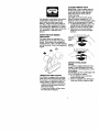
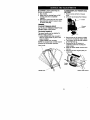
TO REMOVETRIMMER FROM CARTON
1. Remove loose parts included with
trimmer,
2, Cut down two end comers of carton
and lay end panel down flat,
3, Remove all packing materials,
4, Roll trimmer out of carton and check
carton thoroughly for additional loose
parts.
HOWTO SET UPYOURTRIMMER
TO UNFOLD HANDLE
IMPORTANT: Unfold handlecarefully so as
not to pinchor damage conl_l cables.
1. Loosen handle knob enough to allow
upper handle to be unfolded from the
shipping position.
2. Raise upper handle section into place
on lower handle and tighten handle
knob.
3. Remove handle padding holding
tdmmer head control bar to upper
handle.
Your trimmer handle can be adjusted for
your trimming comfort. Refer to "ADJUST
HANDLE" in the Service and Adjustments
section of this manual.
Upper handle
Liftup
knob
handle
5
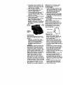
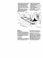
KNOW YOUR TRIMMER
READ THIS OWNER'S MANUAL AND SAFETY RULES BEFORE OPERATINGYOUR
TRIMMER. Compare the iluskatlenswithyour b'immerto familarize yourself withthe location
ofvariouscontrolsand a_ustments. Save thismanualfor futurereference.
It_se
symlx)Is may appear on your trlmmer or In li_mture supplled v_th the produ_. Learn and unde_tand
lING
Ii_JOUS _Y
ORDEATH
_
0
C_T_N
ENGI_
_F
FAST
._LOW
FUEL
OiL
Throttle
Starter handle
Engine oil cap
Chassis
IMPORTANT: ThistrimmerIs shipped
WITHOUT OIL OR GASOUNE in the engine.
Tdmmer head control bar - must be held
down to the handle to engage b'immerhead.
Releaseto st_ the trimmerhead.
Palmer- pumpsadditionalfuelfrom the
carburetorto the cylinderfor use when
startinga coldengine.
_Trinvner line
Throttle control - usedfor staringand
stoppingthe engine and alows youto select
eitherfast or slewenginespead.
Starter handle - usedforstartingthe engine.
Theoperation
ofanytrimmer
canresultin
foreign
objects
beingthrown
intothe
eyes,whichcanresultinsevere
eye
damage.
Always
wearsafety
glasses
or
eyeshields
whileoperating
yourtrimmer
orperforming any adjustments or repairs.
We recommend a wide vision safety mask
over spectacles or standard safety
glasses.
HOWTO USEYOURTRIMMER
ENGINE SPEED
The engine speed is controlled by a
throttle located on the side of the upper
handle. Fast position is for starting and
normal trimming. Slow is for light trimming
and fuel economy. Stop is for stopping the
engine.
It!
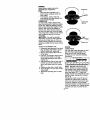
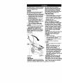
TO ADJUSTTRIMMING HEIGHT
A_,CAUTION: Stop the engine and wait
for eit movLng parts to stop. Disconnect
spark plug wire from spark plug and
place wire where it cannot come in
contact with plug.
The height of cut can be set to six (6)
different positions ranging from 1-1/2
inches to 3 inches. Recommended cutting
height for the average yard is 2 inches.
1. To adjust trimming height, push in the
locking plate tab and move trimmer
head up or down to desired position.
2. Release tab and be sure head is
locked into one of the six (6) height
positions.
Adjustable
Head
Leckinc
Plate Tab
II
TRIMMER HEAD DRIVE CONTROL
Your trimmer is equipped with a trimmer
head drive control bar which will require
the operator to be positioned behind the
trimmer handle to operate the trimmer.
• Tnmmer head rotation is controlled by
holding the tdmmer head control bar
down to the handle.
• Trimmer head rotation will stop when
the control bar is released.
BEFORE STARTING ENGINE
ADD OIL
Yourtrimmer is shipped without oil in the
engine. For type and grade of oilto use,
see "ENGINE" in the Maintenance section
of this manual.
_, CAUTION: DO NOT oved_L|engine with
oil, or it will smoke on startup.
1. Be sure trimmer is level and area
around eil fill is ctean.
2. Remove oil dipstickfrom oilfill spout.
Make sure that rim of spout is clean.
7
3. You receive a 20 oz. container of oil
with the unit. Slowly pour 3/4 (15 oz.)
of the oil from the container down the
oil fill spout into the engine.
4. Wait one minute to allow oil to settle.
Insert and tighten dipstick, then
remove it to check oil level.
5. Continue adding small amounts of oil
and rechecking the dipstick until it
reads full. DO NOT overfill, or engine
will smoke on startup.
6. Always be sure to retighten oil dipstick
before starting engine.
• Check dl level beforeeach use. Adddlif
needed. Fil tofull ien on clpsUck.
• Changethe ol afier every 25 hoursof
operaUonor each season. You may need
to change the oilmore oftenunderdusty,
dirtyconditions.
Gasoline
oilcap
spilled oil or fuel. Do not store, spill or
use gasoline near an open flame.
TO START ENGINE
1. To sta_ a celd engine,push pdmerthren
(3) timesbe_ere'_ing tostaff. Usea firm
push. Thisstep is notusuallyneo_ssary
when stsr_ngan engine whichhas
alreadyrun for a few minutes.
2. Move thmtUecenlzoflevertofast position.
3. Hold upperhandlefirmly and pul starter
handlequickly. Do notallow starterrope
to snap back.
TO STOP ENGINE
• To stopengine, move thmti]econtrollever
to stop posi_en.
NOTE: In cooler weather it may be
necessary to repeat pdming steps. In
warmer weather overpriming may cause
flooding and engine will not start. If you
do flood engine, wait a few minutes
before attempting to start and do not
repeat pdming steps.
(Discard
debds plug
inside)
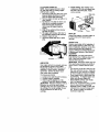
ADD GASOUNE
NOTE: Before fillingfuel tank, remove
and discard the debris plug that is inside
the tank.
• Fil fuel tack. Use fresh, dean, regular
unleadedgasolinewith a minimumof 87
octane. Do not mixoilwith gasoline.
Purchasefuel in quantitiesthat can be
usedwi_ 30 days to assurefuel
freshness.
_;kWARNING: Experience indicates that
alcohol blended fuels (called gasohel or
using ethanol or methanol) can attract
moisture which leads to separation and
formation of acids during storage. Acidic
gas can damage the fuel system of an
engine while in storage. To avoid engine
problems, the fuel system should be
emptied before storage of 30 days or
longer. Drain the gas tank, start the
engine and let it run until the fuel lines
and carburetor are empty. Use fresh fuel
next season. See Storage Instructionsfor
additional information. Never use engine
or carburetor cleaner products in the fuel
tank or permanent damage may occur.
CAUTION: Fill to bottom of gas tank
filler neck. Do not overfill. Wipe off any
8
Throttle control_
Starterhandle__
TRIMMING TIPS _
_
_
• Set the throttlecontrol in the fast
position. If the wends or grass are fall
and thick, operate the trimmer at a
slower walking speed.
• Frequently clean the undersideof the
tdmmer to remove any grass build up.
Keep top of engine around starter clear
and clean of grass clippings and chaff.
This will help engine air flow and extend
engine life.
• For best resultsand longer lastingline,
use the ends of the line to do the cutting.
This is easily done by moving slowly
through very thickand heavy weeds.
• Use the left side of tdmmerwhen
trimming along fences, walls, fiowerbeds
and other such objects.
• If trimmer lines become too short,it will
take longer to complete the job. ff
trimmer lines are worn to less than haft
their original length, they shouldbe
replaced. See =TO REPLACE TRIMMER
LINE" in the Maintenance section of this
manual.
Tdmmer head contactwith concrete,
asphalt or other hard surfaces may
cause premature wear of the ball on .
bottom of trimmer head.
M...TE,..CESC.EOULE
REGULAR
SERVICE
T
R
/_'(_'4_:;R-_,/_7_"
Check for Loose Fasteners
SERVICE r_DATES
I_
Clean Trimmer
It/
it/
It/
I
M
Clean Under Engine Cover
fl_2
M
Check drive Pelt!pulleys
R
Check/Replace Trimmer Lines
II_s
Check Engine Oil Level
II/
It/
v"
E
Change Engine Oil
Ik/t,2
N
Clean Air Filter
If
Inspect
V t
I
NE Ctean
Muffler
or Replace
Spark
Plug
2
(1_
Replace Air Filter Paper Cadddge
1_2
1 - (_ange more olt_n when op_'atlng undm"a hear'/load or in high_t
2 - Se,vic_ m_e ol_m when opecatingin dldy or dusty cordit _ns.
3 - Replace _im_m" qi_ "t_en they ha,._ w_n to halftheir original length
GENERAL RECOMMENDATIONS
temperature6.
IMPORTANT: Do not oil or grease plastic
wheel hearings. Viscous lubricantswill
attract dust and dirt that will shorten the
life of the self- lubricating bearings, If you
feel they must be lubricated, use only a
dry, powdered graphite type lubricant
sparingly.
The warranty on this tdmmer does not
cover items that have been subjected to
operator abuse or negligence. To receive
full value from the warranty, operator must
maintain tdmmer as instructed in this
manual.
Some adjustments will need to be made
periodically to propedy maintain your unit.
All adjustments in the Service and
Adjustments section of this manual should
be checked at least once each season.
Once a year, replace the spark plug
and replace air filter element. A new
spark plug and clean/new air filter
element assures proper air-fuel
mixture and helps your engine run
better and last longer,
Follow the maintenance schedule in
this manual.
BEFORE EACH USE
1. Check engine oil level.
2. Check for loose fasteners,
3. Clean under engine cover.
LUBRICATION
To prolong the useful life of your trimmer,
change engine oil as recommended in
this section of Owner's Manual.
PRODUCT
SPECIFICATIONS
Serial No.
Date of Purchase:
...............
Gasoline "l_jpe:
Unleaded Regular
Gasoline Capacity:
1.25 Quarts
OII Type:
SAE 30 (Above 32° F)
(API-SF-SJ)
SAE 5W-30 (Betow 32° F)
Oil Capacity:
20 Ozs.
Spark Plug :
Champion J19LM
(Gap: .030")
or RJ19LM
Trimmer Une Dla.:
.155 inch
Trimmer Une Length:
18.75 inches
The model and serial numbers will be
found on a decal attached to the rear of
the trimmer. Record both serial number
and date of purchase in space provided
above,
9
TRIMMER
Always
observe
safety
ruleswhen
performing
anymaintenance.
"nRES
Keep
tiresfreeofgasoline,
oil,or
insect
control
chemicals
whichcan
harmrubber.
Avoid
stumps,
stones,
deeprots,
Trimmer line
sharp objects and other hazards that
may cause tire damage.
TR]MMERUNE
For best results, replace trimmer lines
when they have worn to half their original
length. Use .155 inch diameter trimmer
line. Cut new tdmmer line length to 18-314
inches. After new line is installed on
trimmer head, check all lines so they do
not vary more then one (1) inch in length.
This is important to make sure the tdmmer
head is balanced and will not vibrate
abnormally.
• iLWARNING: Use only the specified
trimmer line. Do not use other materials
such as wire, stdng, rope, etc. Wire can
break off during trimming and become a
dangerous missile that can cause sedous
injury.
TO REPLACE TRIMMER LINE
1. Disconnect spark plug wire from spark
plug and place wire where it cannot
come in contact with spark plug.
2. Remove worn trimmer line from line
carder plate.
3. Fold new, cut to length, trimmer line in
half and insert folded end through
carder plate opening to back side of
retainer clip.
4. With folded end of line at back side of
retainer clip, pull line outward until
line is fully seated under the retainer
clip.
5. Repeat on other side of carder plate.
6. Check all lines to be sure they are the
same length.
7. Reconnect spark plug wire to spark
plug.
Carder plate
opening
Retainer dip
ENGINE
LUBRICATION
Use only high quality detergent oil rated
with API service classification SF-SJ.
Select the oil's SAE viscosity grade
according to your expected operating
temperature.
SAlE VISCOSITY
GRADES
NOTE: Although multi-viscosity oils
(5W30, 10W30 etc.) improve starting in
cold weather, these multi-viscosity oils
will result in increased oil consumption
when used above 32°F. Check your
engine oil level more frequently to avoid
possible engine damage from running
low on oil.
Change the oil after every 25 hours of
operation or at least once a year if the
unit is not used for 25 hours in one year.
Check the crankcase oil level before
starting the engine and after each five (5)
hours of continuous use. Tighten oil plug
securely each time you check the oil
10 leVel.
TO CHANGE ENGINE OIL
NOTE: Before tipping tdmmer to drain
oil, drain fuel tank by running engine
until fuel tank is empty.
1. Disconnect spark plug wire from spark
plug and place wire where it cannot
come in contact with spark plug.
2. Remove engine oil cap; lay aside on a
clean surface.
3. Tip tdmmer on its side as shown and
drain oil into a suitable container.
Rock tdmmer back and forth to
remove any oil trapped inside of
engine.
4. Wipe off any spilled oil from trimmer
and side of engine.
5. Fill engine with oll (See "ADD OIL" in
the Operation section of this manual).
6. Replace engine oil cap.
7. Reconnect spark plug wire to spark
plug.
Containel
AIR FILTER
Your engine will not run properly and may
be damaged by using a dirty air filter,
Replace the air filter every 100 hours of
operation or every season, whichever
occurs first. Service air cleaner more
often under dusty conditions.
TO CLEAN AIR FILTER
1. Loosen screw and tilt cover to remove.
2. Carefully remove cartridge.
3. Clean by gently tapping on a fiat
surface. If very dirty, replace cartddge.
_.CAUTION: Petroleum solvents, such as
kerosene, are not to be used to clean
cartridge. They may cause deterioration of
the cartridge. Do not oil cartddge. Do not
use pressudzed air to clean or dry
cartddge,
4. thstaU carfrkk:je, then replace cover
making sure the tabs are aligned with
the slots in the back plate. Fasten
screw securely.
k p_ate
Slots
Cover
tabs
ge
Cover
MUFFLER
Inspect and replace corroded muffler as
it could create a fire hazard and/or
damage.
SPARK PLUG
Replace spark plugs at the beginning of
each mowing season or after every 100
hours of operation, whichever occurs first.
Spark plug type and gap setting are
shown in "PRODUCT SPECIFICATIONS"
in Maintenance section of this manual.
CLEANING
IMPORTANT: For best performance,
keep trimmer free of built-up grass and
trash. Clean the underside of your
tdmmer after each use.
A.CAUTtON: Disconnect spark plug wiru
from spark plug and place wire where it
cannot come in contact with the spark
plug.
• Turn trimmer on its side. Make sure air
filter and carburetor are up. Clean the
underside of your trimmer by scraping
to remove build-up of grass and trash.
• Clean engine often to keep trash from
accumulating. A clogged engine runs
hotter and shortens engine life.
• Keep finished surfaces and wheels
free of all gasoline, oil ,etc.
• We do not recommend using a garder
hose to clean trimmer unless the
electrical system, muffler, air filter and
carburetor are covered to keep water
out. Water in engine can result in
shortened engine life.
11
A, CAU'RON: Before performing any
service and adjustments:
1. Stop engine.
2. Make sure the rotating lines and all
moving parts have completely
stopped.
3. Disconnect spark plug wire from spark
plug and place where it cannot come
in contact with plug.
TRIMMER
TOADJUSTTRIMMING HEIGHT
See "TOADJUST TRIMMING HEIGHT' in the
OperalJonsectionof thismanual.
TO ADJUST HANDLE
The upper handle may be adjusted to
different height positions.
• Loosen handle knob only enough to
allow the upper handle to pivot to the
desired position.
• Tighten handle knob securely.
NOTE: The handle knob and bolt may be
reversed for left handed operation.
Upper handle
TO REMOVE/REPLACE TRIMMER HEAD
DRIVE BELT
1. Remove screw at front of chassis
cover.
2. Lift cover up and away from trimmer.
Chassis
3. Remove the two (2) screws on sides
of tdmmer secudng the debris shield.
4, Turn tdmmer on its side with carburetor and fuel cap up.
5. Remove the two (2) screws on
underside of trimmer securing the
debds shield.
6. Slide the debris shield rearward and
remove.
7. Remove belt from engine pulley on
crankshaft.
,I
i #
pulley
Debris shield screws
Handle knot
12
8. Remove belt from tdmmer head pulley.
9. Note the position of the control cable
and idler return spdng, then remove
idler assembly from chassis and
remove belt and idler from trimmer.
10. Remove belt from idler assembly by
removing bottom belt keeper and idler
pulleys.
11 .Assemble new belt, idler pulleys and
bottom belt keeper to idler bracket.
Tighten pulley bolts securely.
NOTE: Be sure belt is inside top belt
keeper on idler assembly.
12. Position belt and idler assembly in
tdmmer, reconnect idler spdng and
assemble idler to chassis.
13.Install belt around tdmmer head pulley
and engine pulley.
14.Replace debds shield and tighten the
four (4) screws securely.
15.Replace chassis cover and tighten
screw securely.
Always use Craftsman replacement parts
to assure proper fit and long life.
Idler bracket
Engine pulley
Flat idler
Chassis
\.
÷
/
I
k
_b,
Bo_om
belt
keeper
Trimmer head pulley
ENGINE
ENGINE SPEED
Your engine speed has been factory set.
Do not attempt to increase engine speed
or it may result in personal injury. If you
believe that the engine is running too fast
or too slow, take your unit to a Seers or
other qualified service center for repair
and/or adjustment.
CARBURETOR
Your carburetor has a nonadjustable fixed
main jet for mixture control. If your engine
does not operate propedy due to sus-
pected carburetor problems, take your
unit to a Sears or other qualified service
center for repair and/or adjustment.
IMPORTANT: Never tamper with the
engine governor, which is factory set for
proper engine speed. Overspeeding the
engine above the factory high speed
setting can be dangerous. If you think the
engine-governed high speed needs
adjusting, take your unit to a Sears or
other qualified service center, which has
proper equipment and experience to
make any necessary adjustments.
13
Irnmediat_y
prepare
yourkirnmer
for storage
at the endof the seasouor if the unitwillnot
be usedfor30 daysor more.
TRIMMER
When lrimmeris to be storedfor a periodof
time,dean it horoughly, removeall dirt,
greuse,leaves,etc. Store in a dean, dryarea.
1. Clean entirehmmer (See "CLEANING" in
the Maintenancesectionof tblsmanuel).
2. Lubricateas shownin the Maintenance
sec_onof thismanuel.
3. Besure thatall nuts, bolts,screws,and
pinsare securelyfastened. Inspect
_
partsferdamage,
breakage
and
wear. Replace if necessery.
4. Touch up all rustedor chippadpaint
surfaces;sand lightlybeforepaletlng.
HANDLE
You canfold yourkimmer handlefor sterage.
• Leosen handle knob enough to allow
upper handle to be folded forward.
IMPORTANT: When folding the handle for
storagaar trauspodafion, be sure to fold the
handle as shownor you may damage the
coubolcables.
tankduringstorage.Also, experience
indicates that alcoholblended fuels (called
gasoholor usingethanelor methanol)can
at_act moisturewhichleads to separation
andformation of adds dunngstorage.Acidic
gas can damagethefuel systemof an
engine while in storage.
1. Drain the fuel tank.
2. Start the engine and let it run until the
fuel lines and carburetor are empty.
• Never use engine or carburetor cleaner
products in the fuel tank or permanent
damage may occur.
• Use fresh fuel next season.
NOTE: Fuel stabilizeris an acceptable
altercate in minimizingthe formatleaof fuel
gum depositsduringstcraga. Add stabilizer
to gasolinein fueltank or storagecontainer.
Alwaysfellewthe mix ratio foundon stabilizer
container.Run engineat least 10 minutes
afteraddingstabilizerto allow he stablizerto
reachthe carburetor. Do out drainthe gas
tank and carburetor if using fuel stabiizor.
ENGINEOIL
Drain oil (with engbe warm) and replacewith
cleanengineoil. (See "ENGINE" in the
Maintenancesectionof his manual).
CYUNDER
1. Remove spark plug.
2. Pour one ounce (29 ml) of oil through
spark plug hole into cylinder.
3. Pull starter handle slowly a few times
to distribute oil.
4. Replace with new spark plug.
OTHER
• Do notstore gaselinefrorn one seasonto
another.
• Replaceyear gasoline can if yourcan
startstorust. Rustand/ordirtin your
gasolinewill cause problems.
• If_,
store yourunit indoorsand
coverit to give protectionfn_mdustand di't.
• Cover your unitwitha suitableprotective
coverthat does not retain moisture. Do
not use plastic. Plas_ccannotbreathe
whichallowscondensetlonto form and wil
cause year unitto rust.
Handle knob
IMPORTANT: Nevercovertdmmerwblle
engineand exhaustareas are slJlwarm.
ENGINE
d_,CAUTION: Never store the trimmer
FUELSYSTEM
with gasoline in the tank inside a building
where fumes may reach an open flame or
IMPORTANT: It is irn_t
to preventgum
depositsfrom forming in essential fuelsystem spark. Allow the engine to cool before.
parts suchas carburetor,fuelfilter,fuel hoseor14 stodng in any enclosure.
handle
TROUBLESHOO_NG
PROBLEM
Doesnotstart
CORRECTION
CAUSE
1. Dirtyairfil_n
2. Out of fuel.
3. Stale fuel.
4. Water in fuel.
5. Spark plug wire is
disconnected.
6. Bad spark plug.
7. Throttle control lever not
in correct position
(if equipped).
1. Clean/replace air filter.
2. Fill fuel tank.
3. Drain tank and refill with
fresh clean fuel.
4. Drain fuel tank and
carburetor and refill tank
with fresh gasoline.
5. Connect wire to plug.
6. Replace spark plug.
7. Move throttle lever to FAST
position.
Loss of power
1. Dirty air filter.
2. Buildup of grass, leaves,
and trash under tdmmer.
3. Too much oil in engine.
4. Walking speed too fast.
1. Clean/replace air filter.
2. Clean underside of tdmmer
and trimmer head.
3. Check oil level.
4. Trim at slower walking
speed.
Excessive
Vibration
1. Lines uneven or broken.
2. Loose nuts or bolts.
1. Check tdmmer lines.
2. Check all hardware,
including engine bolts.
3. Check/repair tdmmer head.
3. Damaged tdmmer head.
Starter rope hard
topull
1. Bent engine crankshaft.
1. Contact a Sears or other
qualified service center.
Loss of head
drive
1. Belt not driving.
1. Put belt on pulleys or
replace belt if broken.
Hard to push
1. Handle height position not
dght for you.
1. Adjust handle height
to suit.
Poor trimrnlng
performance
1. Trimmer line length is
too short.
1. If line is worn or broken to
half original length,
replace line.
2. Move throttle lever to FAST
position.
2. Throttle control lever not
in correct position
(if equipped).
Trlmroer head
does not
retain line
1. Trimmer line not
propody installed.
2. Broken line retainer clip.
3. Incorrect size of
trimmer line.
15
1. Follow instructionsin
Maintenance section.
2. Replace stdng carder plate
assembly.
3. Use .155 diameter
trimmer line.
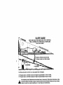
SLOPE GUIDE
SIGHT AND HOLD THIS GUIDE LEVEL WITH A VERTICAL
TREE, A CORNER OF A STRUCTURE, A POWER LINE
.....
POLE, OR A FENCE.
Operate a trimmer across the face
of slopes, .ever up or down slopes.
15 DEGREES
Use this guide and do not trim on a slope greater than 15 degrees.
A 10 degree slope is a hill that increases in height at approximately 1.7 feet tn 10 feet..
A 15 degree slope is a hill that increases in height at approximately 2.5 feet In 10 feet..
Use extreme care at all times and avoid sudden turns or maneuvers. Follow other Instructions
_lb
in this
anual forsafety
trimming
on slopes. on
Operate
a trimmer
across
the face ofslopes, never uP or down
slopes.
Use extra in
care
when operating
or near
slopes and
obstrucUons.
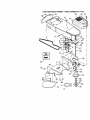
CRAFTSMAN
WEEDTRIMMER-MODEL
NUMBER917.773701
29
18
31
32
21
26
27
23
14
26
27
25
32
CRAFTSMAN
WEEDTRIMMER-MODEL
NUMBER
917.773701
KEY
NO,
PART
NO,
-- -
2
3
4
8
9
10
11
12
13
14
15
16
17
18
19
2O
21
22
23
24
25
26
E7
28
29
31
32
33
34
35
150406
169791
STD502502
169621)(479
150076
169797X479
170980
136376
170681
170682
170554
153638
132004
_o426
176963
177814
156755
178700X004
15(_78
52160
57143
752063
83923
176999
178364
111190X
83816
178365
8689eX004
756634
178845
Available accessories
7133623
7133000
7179991
DESCRIPTION
Engine, Bdggs & St ration,
Madel Number 122H02-0110_ 1
(See Breakdown)
Bolt, Engine Moun'Jng 3/0.16
Pulley, Engine (Includes Setscrew, Key #4)
Setscrew, Pulley
Handle, Lower
Screw, Hex Washer Head 5/16-18 x .75
Handle,Upper
Bolt, Handle
Knob,Handle
Adjuster, Handle, Inside
Adjuster, Handle, Outside
Spdng, Handle Adjust
Guide, Rope
Locknut 114 x 20
WimT_m
Control Bar
Throttle Control
Screw, Hex Washer Head
Axle Shaft Assembly
Screw, Hex Washer Head 5/16-18 x ,75
Spacer, Axle
Washer, Wave
Wheel, 14 x 2
Hex Flange Locknut 3/8-16
Drive Control
Decal,Warning
Clamp,Cable
Screw
Decal, Warning
Bracket, Upstop
Screw, Thd. Roll. #10-24 x 1/2
Owner's Manual, English/Spanish
not included with trimmer:
Gas Can (2.5 gal.)
SAE 2OW Oil (20 oz.)
Trimmer Line (pack of 24 strings, .155 dia,)
NOTE: All component dimensions given in U.S. inches
1 inch = 25.4 mm
33
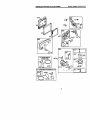
CRAFTSMAN WEED TRIMMER- - MODEL NUMBER 917.773701
20
14
44
43
4
23
24
13
0--31
27
32
34
21
CRAFTSMAN WEED TRIMMER-- MODEL NUMBER 917.773701
KEY
NO,
1
2
3
4
5
6
7
8
9
10
11
12
13
14
15
16
17
18
19
2O
21
22
23
24
25
26
27
28
29
3O
pART
NO,
174031X558
169802
173715
169790
172145X004
169042
173716
751592
166043
160829
155552
173717
174719
145212
173811
177871
57808
857698
175301
170553
149746
STD541137
STD551137
STD551697
169792
172551
174549
172520
169769X479
174543
31
32
33
34
35
36
37
38
39
4O
174581
176973
172519
174544
52784
172516
174586
172523
172636
172342
41
42
43
44
45
46
47
48
91
52
174029
174036
174042
174035
174569X479
17060408
76399
59931
177972
176948
DESCRIP'RON
Chassis Assembly
Line, Trimmer .155 diameter x 18.75 long
Screw, Self-Tapping 5/16-18 x 1
V-Belt
Bracket, Idler
PuKey, Idler, V-Groove
Bolt, Hex Head 3/8-16 x 1,25
Locknut, Hex 3/8-16
Pulley, Idler, Flat
Bolt, Shoulder
Locknut 9/16-18
Spacer
Bolt, Shoulder
Locknut, Flange
Spring, Return
Shield, Debris
Screw 114-20 x 112
Screw #10-24 x 3/4
Skirt
Cover, Chassis, Top
Screw #10-24 x 1-3/4
Nut 3/8-24 UNF
Washer, Lock 3/8
Washer, Flat 3/8
Pulley, Driven
Spacer, Pulley
Bearing
Jaekshaft
Cover, Chassis, Bottom
Spindle Housing Assembly
(* Includes Upper Bearing, Key #27)
Ring, Retain{ng, External, 17ram
Splfng, Locking Plate
Locking Plate
Carrier Plate Assembly
Washer
Cover, Bearing
Ring, Retaining, Internal, 40ram
MowBall
Bolt, Mow Ball
Head Assembly, Complete
(Includes Key Numbers 22-28, 30-39)
Spacer
Decal, Instruction
Decal, InstrLlCtlon
Decal Chassis Cover
Belt Keeper, Bottom
Screw
Screw
Nut
Skirt
Screw #10-16 x 518
NOTE: All component dimensions given tn U.S. inches
1 Inch = 25.4 mm
35
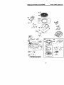
BRIGGS & STRATTON 4-CYCLE ENGINE
11019LABEL
Kff I
MODELNUMBER122H02-O11O-D1
684_
842_
383_
52!
I
524 €
635
33
1095VALVE
GASKET SET
ir REQUIRES SPECIALTOOLS
TO INSTALL. SEE REPAIR
INSTRUCTION MANUAL.
11058 OWNER'S MANUAL 1
36
BRIGGS & STRATTON 4-CYCLE ENGINE
MODEL NUMBER122H02-0110-D1
188_
e21_'_
968
967
445
163_
I
977 CARBURETOR
GASKET SET
6t7_
365
633_
12
121 CARBURETOR OVERHAUL KIT
_'--]
633_
617(_-_
163
27e
37
BRIGGS & STRATTON 4-CYCLE ENGINE
MODELNUMBER122H02-0110-DI
332
3O5
eTo@ .o_
6s'_
592 _
I1©
18_._.1
58(_
I
689 O
456
s97_
38
60
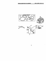
BRIGGS & STRATTON 4-CYCLE ENGINE
MODELNUMBER122H02-0110-DI
358 ENGINE GASKET SET
3_)
20_
842_
5240
615_
404 _)
_
227
39
668_
BRIGGS & STRATTON 4-CYCLE ENGINE
KL=Y
NO.
PART
NO.
1
2
3
4
5
7
6
9
10
11
12
13
15
16
20
22
23
24
25
493260
392269
299819
493279
691160
692249
695250
272481
691125
691781
692232
690912
691686
691451
399781
691092
622315
222698
499429
499430
499431
499432
499425
499426
499427
499428
691866
499423
499424
691664
695759
262651
262652
691270
691270
694085
692194
691997
690548
691449
26
27
28
29
32
32A
33
34
35
36
37
40
43
45
46
DESCRIP'flON
Cylinder Assembly
Ed-BushSig/Seal
• Seal-Oil (Magneto Side)
Sump4Er@ne
Head-Cyfinder
•+ Gasket-Cylinder Head
Breather Assembly
•+ Gasket-Breather
Screw (Breether Assembly)
Tube*Breather
• Gasket-Crankcase
Screw (Cylinder Head)
Plug-Oil D{ain
Crankshaft
• Seal-Oil (PTO Stde)
ScrewIEngineSump)
Rywheel
Key4Clywheel
P{ston Assembly (Standard)
Piston Assembly (.010" O.S,)
Piston Assembly (,620" O.S.)
Piston Assembly (.030. O.S)
Ring Set=Piston (Standard)
Ring Snt-Piston (.010. O S)
Ring Set-Piston (020.O.S.)
Ring Set-Piston (.030" O.S,)
Lock-Piston Pin
Pin-Piston
Rod-Conne_ng
Screw (Conneeting Rod)
Screw (Con rlecting Rod)
Valve-Exhaust
Valve-Intake
Spring-Valve (Intake)
Spd ng-Valve (Exhaust)
Guard_Flywheel
Retainer-Valve
Slinger-Governor/Oil
Tappet-Valve
Camshet_
MODELNUMBER122H02-0110-D1
NO.
PART
NO,
48
498826
50
51
54
55
58
60
65
78
81
95
97
104
t17
497465
272169
691650
691421
692259
281434
6690837
691168
691740
691636
493267
691242
494870
497315
498260
694468
6912{_
398187
398169
69:_981
690979
691753
2-/2653
691050
690877
690940
691829
690319
692031
690783
690798
271716
690940
692038
696307
691108
690450
690345
121
127
130
133
134
137
146
159
163
187
188
190
202
209
222
227
265
276
287
300
304
305
306
307
4O
OESCRIPI_DN
Shod BLock(Replacement
Engine 12D602-6915-B1)
Manlfold-lr_ake
• Gasket-I_ake
Screw (lutake Manifold)
HOUsing-RewindStarter
Rope-Starter (Cut to Length)
Grip-Starter Rope
Screw (Rewind Starter)
Screw (Fly_41ealGuard)
Lock-Muffler Screw
Screw (Throttle Valve)
Shaft-Throttte
PIn-Roet Hinge
Jet-Main (Standard)
Jet-Main (High Altitude)
Kit-Carburntor Overhaul
O Plug_WeLch
Valve-Threttle
Roat-Carburetar
O Valve-Needle/Seat
2_ Gasket-Floet Bowi
Key-T_ni_
Bracket-Air Cleaner Primer
•(_: Gasket-Air Cleaner
Line-Fuel (Cut to Length)
Screw (Control Bracket)
Screw (Fuel Tank)
Link-Mechanical Governor
Spring-Governor
Bracket-Control
Control Lever-Governor
C_amp-Cadng
:_ Sealing Washer
Screw (Dipstick Tube)
Mtlffler
Housing-Borer
Screw (Blower Housing)
Shield-Cylinder
Screw (Cylinder Shield)
BRIGGS & STRA'rTON 4-CYCLE ENGINE
NO.
pARr
NO.
332
333
334
337
356
358
363
365
383
404
425
443
445
455
456
459
505
523
624
525
629
562
563
564
584
585
692
597
601
604
608
613
615
616
617
621
633
635
668
670
690662
802574
691061
802592
692390
497316
19069
692524
89838
69(_72
690670
692523
491588
691219
692299
281505
231082
495264
692296
495265
691923
92613
691138
690664
692342
691879
690800
691696
95162
691767
497680
691340
690346
691306
270344
692310
691321
66538
493823
692294
DESCRIPTION
Nut(Flywheel)
Armsture_tage, eto
Screw (Am_ture Magneto)
Spark Plug
W]re*Stop
Engine G_ket Set
Flywheel Puller
Screw(Carburetor)
Wrench-Spark Plug
Washer (Governor Crank)
Screw (Air Cleaner Cover)
Screw (Air Cleaner Pdmer Base)
Fiiter-AJrCleaner Cartridge
Cop-Flyv/neel
Plate-pav_ Frintlon
PawI-Ratchet
Nut (Governor Control Laver)
Dipstick
• SeaI-DIpstickTube
Tube-D_pstick
Gr_nmst
Bo5 (Governor Control Lever)
Screw IDebds Guard Gover )
Screw (Control Cover )
Cover*Breether Passage
• Gasket-Breather Passage
Nut (Rewind Starter)
Screw (Pawt Fricgon Plete)
Clampq-lose
Cover-Control
Stader-Rev_nd
Screw(Muffler)
Retainer-Governor Shaft
Crank*Governor
_
SeaI-ORing(tntakeManlfold)
Switch-Stop
_
SeaI-Choke/Th ruttle Sha6
Boot-SparkplL_g
• Spacer (Includes 2)
Spacer-FuelTank
MODEL NUMBER122HO2-O110-al
_
NO.
pART
NO.
684
6_0345
689
703
741
842
847
851
869
870
871
949
949A
957
966
967
968
970
691855
696309
691830
691031
692017
493880
691155
690380
262001
63709
696306
696310
397974
496116
493537
692298
691669
972
975
976
977
1019
1036
1058
1059
1095
1210
1211
1229
496224
493640
694395
498261
494256
696035
274978
692311
498528
498144
498144
696308
DESCRIPTION
Scre
(Breather passage Cover)
Spring-Friction
Clip
Goat-liming
• Seal*O Ring (Dipetlck Tube)
Assembly-Dipstick/Tube
TermlnaI-Sparkplug
Seat-Valve (Intake)
Seat*Valve (Exhaust)
Bushing-Guide (Exhaust)
Bushing-Guide (intake)
Guard-DehdsScreen
Guard-Debris Screen
Cap-Fuel Ta_k
Base-AirCleaner Pdmer
Fiiter-Pre Cleaner
Cover-Air Cleaner
Screw
(Air Cleaner Primer Bracket)
Tank-Fu_
BowI-Rc,at
Pdrner-Carburetor
Set-Carburetor Gasket
Kit-Label
Label-Emissions
Owner's Manual
KJt_crew/_/asher
Set-Valve Gasket
As_e mhly-PutleyiS pring(Pulley)
Asse mhly*P ulley/S pdng (Spdng)
Extension-Blower Housing
•
included in Engine Gasket Set, Key #358
Included in Carburetor Overhaul Kit, Kay #121
/; Ir_cludedin Carburetc_ Gasket Set, Key #977
+ Included in Valve Overhaul Kit, Key #1695
NOTE: All component dimensions given in U,S. inches
1 inch = 25.4 mm
41
Forrepairofmajorbrand appliances inyourown home ....
no matter who made it, no matter who sold _
1-800-4-MY-HOME e
(1"800469-4663)
._e,
day(_r_ht
:_i_i_i_i_ii_i
,,_,,_®:_
::iiiiiiiii//::_/_
_,iii_i:
(U.S.A. and Car,aria)
::::::::::::::::::::
iiiiiiiiiii
For repairof carry-in productslike vacuums, law_equipment,and
electronics,callfor thenearestSears Pads and Repair Center.
_
;_,_/_
::::::::::_:::::::::
::::::::::::::::::::::::
_::::::::::::::::::
1-800-488-1222
i_/€_e,dayo_n_l (U.S.A.
o_)
_iiiiiiiiiiiiii
www.seel_.Coffl
iiiiii:iiiiiiiiiiiiii
i/_iiiiiiii_i_
Forthe replacementparts,accessoriesend owner'smanuals
thatyouneed to do-R-yourself,canSears ParlsDirect_!
1-800-366-PART
_iiiiiNiiii
iiiiiiiiiii
6 a.m.- 11 p.m,, 7_ysa_ek
www_com/padsdimct
To purchase or inquire about a Sears Service Agreement
or Sears Maintenance Agreement:
1-800-827-6655 (U.S.A)
7 a.m. - 5 p.m., CST, Mo_, - S_L
1-800-361-6665 (Canada)
9a.m.-8pJ'n.EST,
M-F,4p.m.S_t
® Registered Trademark 11MTrademark / su Service Mark of Sears, Roebuck and Co.
® Marca Registrada / TM Marca de Fdbnca I _ Marca de Sewicio de Sears, Roebuck and CO.
Mc Marque de commerce I MDMarque d_posee de Sears, Roebuck and CO.
178845 02.22.01
BY
Printed in U.S'A.