1
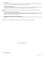
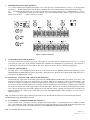
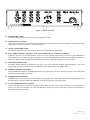
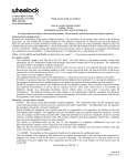
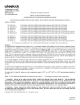
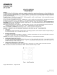
273 Branchport Ave.
Long Branch, N.J. 07740
(800) 631-2148
www.wheelockinc.com
Thank you for using our products.
INSTALLATION INSTRUCTIONS
MODEL MX-8 MIXER
Use this product according to this instruction manual. Please keep this instruction
manual for future reference.
GENERAL:
The MX-8 Mixer is an eight channel audio mixer designed to drive power amplified speakers in a telephone paging application or as
the input mixer for a commercial PA system. The MX-8 offers a choice of ten different inputs: five low impedance microphone
inputs, one telephone paging input, three high impedance auxiliary inputs and one PATCH IN input. The MX-8 allows eight of these
inputs to be used simultaneously: four microphone inputs, a choice of a telephone paging input or a fifth microphone input, and three
auxiliary inputs.
The front panel of the mixer features individual input level controls; as well as, MASTER gain and TREBLE / BASS controls, LO
CUT horn protect switch, LIMITER (ALC) ON/OFF switch, power ON indicator, INPUT PEAK indicator for the eight input
channels, and an OUTPUT PEAK indicator.
A built-in LIMITER circuit compensates for the varying voice levels and paging styles of the people who have access to telephone
paging or a microphone input. The LIMITER maintains rated output without distortion when input level exceeds rated input by as
much as 20dB. The LIMITER circuit affects only the MIC and TEL inputs.
Note that (AUX 1) auxiliary input (i.e., background music, tone generator, etc.) will automatically be soft muted whenever a
telephone page or a microphone page is generated. After completion of the page, the music will return to its original level.
On the rear panel, there is a power ON/OFF switch with a switched auxiliary AC receptacle, as well as a MIC 5/TEL select switch
and a PRE/POST EQ select switch for the LINE OUT.
All inputs and outputs are connected to the rear panel. Screw terminals are used for the Microphone and Telephone Inputs. Phono
jacks are used for auxiliary inputs, LINE OUT, TAPE OUT, PATCH OUT and PATCH IN.
The mixer operates from 115VAC, 60Hz and has a power consumption of less than 25 watts. There is no external fuse or circuit
breaker. IN THE EVENT THE MIXER DOES NOT POWER UP, HAVE THE TROUBLE INVESTIGATED BY AN
AUTHORIZED SERVICE TECHNICIAN OR RETURN UNIT TO FACTORY.
NOTE: READ THESE INSTRUCTIONS CAREFULLY. FAILURE TO COMPLY WITH ANY OF THE FOLLOWING
INSTRUCTIONS, CAUTIONS AND WARNINGS COULD RESULT IN RISK OF ELECTRICAL SHOCK, IMPROPER
APPLICATION OR INSTALLATION.
NOTE: All CAUTIONS and WARNINGS are identified by the symbol
. All warnings are printed in bold capital letters.
WARNING: TO REDUCE THE RISK OF FIRE OR ELECTRIC SHOCK, DO NOT EXPOSE THIS UNIT TO RAIN
OR MOISTURE.
Copyright 1996 Wheelock, Inc. All rights reserved.
P83241 C
Sheet 1 of 9
1.
UNPACKING:
The mixer was carefully checked before leaving the factory. Inspect shipping container and unit carefully for indication of
improper handling. If the unit has been damaged, make an immediate claim to the carrier.
2.
MOUNTING INSTRUCTIONS:
The mixer is provided with five mounting feet for placement on a shelf. An optional Rack Mount Kit (PA-RMK) is available
for mounting in standard EIA 19” racks. Refer to PA-RMK installation instructions (P83258) for mounting.
CAUTION: These devices are not intended for use in hazardous locations as defined by the National Electrical Code (NEC).
3.
POWER AND GROUNDING (SEE FIGURE 1):
The 115VAC line cord has a three-prong plug which should be plugged into a three wire grounded electric outlet. It is very
important to maintain the mixer ground for safe and trouble-free operation. If there is no grounded electric outlet, connect earth
ground of the AC line cord to a water or steam pipe.
4.
POWER SWITCH AND RECEPTACLE (SEE FIGURE 1):
The ON/OFF power switch located on the rear panel controls both the internal power of the mixer and the accessory IEC female
outlet.
Note: The accessory to be attached and controlled by the ON/OFF switch must not exceed 3 Amps at 115VAC.
Figure 1: Power Connections
5.
SPECIFICATIONS:
P83241 C
Sheet 2 of 9
Table: 1
Description
Inputs
1. Impedance
2. Sensitivity
3. Frequency
Response
4. Signal to Noise
Ratio
5. Type
of Input
6. Controls
7. Indicators
8a. Treble Control
8b. Bass Control
9. Lo-Cut Switch
Automatic
10. Limiter
for Paging
Automatic
11. Mute
Operation
12. Total Harmonic
Distortion (THD)
Outputs from
13. Mixer
14. RFI Protection
15. Environmental
16.
17.
18.
19.
20.
21.
22.
6.
Input Power
Consumption
Weight
Dimensions
FCC
UL
CSA (Pending)
(1) Telephone
600 Ohms
(-16dBM)
125mV
150Hz-15KHz
MX-8
(4) MIC
600 Ohms
(3) AUX
47K Ohms
5mV
225mV
20Hz-20KHz
20Hz-20KHz
Tolerance
----------TEL ± 2dB
MIC ± 1.0mV
AUX ± 20%
±2dB
65dB
Transformer
Isolated/Bal.
65dB
70dB
- 3dB
Balanced or
Unbalanced
Unbalanced
-----Level Control: (1) TEL/MIC5 (4) MIC (3) AUX
BASS, TREBLE, MASTER GAIN
LIMITER Select Switch, LO-CUT Switch
TEL/MIC5 Select, PRE/POST EQ Switch
Green LED - Power On, Red LED - Input Peak Indicator
Output Peak Indicator
-12dB to +12dB at 10KHz
± 3dB
+12dB to -12dB at 100Hz
± 3dB
-6dB at 250Hz
± 1dB
± 2dB Output Level Maintained Without
Clipping, While Exceeding
-----Rated Input Level Up to 20dB.
40dB Muting of AUX 1
with Nominal MIC or TEL Input
-----1%
LINE OUT:
≥ 1V at RL = 150
Ohms
PATCH OUT: ≥ 1V at RL 150 Ohms
TAPE OUT: -10dB from PATCH
OUT
RFI Test: Use CB Transmitter Output
in Same Room - Minimum 20 Ft. from
Amplifier - No Pickup
0 Degrees C-49 Degrees C
85% R.H. Noncondensing
90V-132VAC
50/60Hz
25 Watts Max
12.6 lbs.
3.5"(H) 16"(W) 14"(D)
Part 15
813
CAN/CSA C22.2 No. 1-M-90
± 1%
± 10%
Comments
-----at 1KHz
To Produce
Rated
Output
Ref. 1KHz at .1V
-3dB Roll-Off
“No Hum”
-----Front
Panel
Front
Rear Panel
Front
Panel
Ref 1kHz at .1V
Ref 1kHz at .1V
----------Mute of Music Output
While Page
is Activated
Rated Output
at 1KHz
Line Out - Selectable
PRE/POST-EQ
PATCH OUT = PREEQ
------
------
-----Power Factor Corrected
-------------------------------
-----Universal Input
----------Rack Mount 19"(W)
----------------
TELEPHONE PAGING INPUT (SEE FIGURE 2):
Connect telephone paging interface wires to the input screw terminals marked TIP (+) and RING (-). Set MIC 5/TEL Switch
(rear panel) to TEL position. For Tip and Ring connections to various types of telephone paging access, see Figures 6A, B & C.
For Tip and Ring connections to Wheelock Zone Controls, refer to the specific zone control installation instructions.
P83241 C
Sheet 3 of 9
7.
MICROPHONE INPUTS (SEE FIGURE 2):
(A) Connect balanced low-impedance microphone wires to the input screw terminals marked (+) and (-). To avoid possible
interference, the microphone input cable should be a shielded cable, with the shield connected to the input GND terminal.
(B)
An unbalanced microphone may be connected to the same screw terminals; the signal to (+) and the shield to (-). The (-)
input
terminal must be connected to the adjacent screw terminal marked GND. Install a jumper wire between the
unused screw terminal
and the GND screw terminal.
Figure 2: Input Connections
8.
AUXILIARY INPUTS (SEE FIGURE 2):
To connect an FM tuner, CD player, tape player, tone generator, or any other line level program source to AUX 1, 2 or 3 input
jack on the rear panel, use a single conductor shielded cable terminated in a standard RCA type phono plug. Note that AUX 1
is automatically soft muted by any active MIC or TEL input. Neither AUX 2 nor AUX 3 is muted by paging inputs.
9.
LINE OUT (SEE FIGURE 2):
The LINE OUT is a mixed audio signal which can be selected either before the TREBLE/BASS controls (PRE-EQ), or after
TREBLE/BASS and MASTER gain controls (POST-EQ). The LINE OUT is the main mixer output and the LINE OUT level is
controlled by the MASTER gain control.
10. PATCH OUT - PATCH IN AND TAPE OUT (SEE FIGURE 2):
The PATCH OUT signal is the mixed audio signal before the TREBLE/BASS and MASTER gain controls of the mixer. The
TAPE OUT signal is the same as the PATCH OUT but reduced 10dB for line matching to various recording formats. The
PATCH OUT signal is available for external audio processing, for example, an outboard graphic equalizer. If external audio
processing is used, the resultant signal is to be returned to the mixer at PATCH IN. The insertion of a phono plug at PATCH IN
will replace the internal mixed audio signal with an external audio signal. The insertion of an RCA phono plug into the PATCH
OUT will also disconnect the mixed audio signal from the tone and gain controls, requiring the external processed audio to be
applied at PATCH IN. When using external audio processing, the TREBLE/BASS controls should be set to the center or
balanced position.
Note: The insertion of a phono plug in either the PATCH OUT or PATCH IN will disconnect the internal mixed audio from the
TREBLE/BASS and the MASTER gain controls.
11. TO CONNECT A TAPE RECORDER (SEE FIGURE 3):
A tape recorder can be connected to record live programs selected (all inputs). A separate phono jack is available for TAPE
OUT. The TAPE OUT signal is the same as the PATCH OUT signal but reduced in level by 10dB. Both the PATCH OUT and
the TAPE OUT signals are the mixed audio signal prior to the TREBLE/BASS and MASTER gain controls.
Note: Use shielded cable for interconnection.
P83241 C
Sheet 4 of 9
Figure 3: Connecting a Tape Recorder
12. CASCADING AMPLIFIERS FROM MIXER (SEE FIGURE 4):
The LINE OUT of the MX-8 can be used to feed an AUX input of a PAMX-125 for additional inputs with 125 Watts of power.
Note: Use shielded cable for all interconnections.
Note: The LINE OUT signal can be selected to be output prior to, or after, the TREBLE/BASS controls, (PRE/POST EQ).
Figure 4: Cascading Amplifiers
13. SELF AMPLIFIED SPEAKERS (SEE FIGURE 5):
The LINE OUT signal can be used to drive self amplified speakers. MX-8 output impedance is 150 Ohms.
P83241 C
Sheet 5 of 9
Figure 5: Connecting SA Series Self Amplified Speakers
14. TELEPHONE PAGING ACCESS CONNECTIONS:
Figure 6A: Audio Page Port
Figure 6B: Analog Station Extension Port
Figure 6C: Unused Co Line/Trunk Port or Stand Alone
Telephone
Note: Maximum primary DC current not to exceed 10mA for telephone input.
Refer to Wheelock TPI-100 installation instructions (P82030) for internal control settings and adjustments.
CAUTION: Connect only to PBX or KSU incorporating isolation from public telephone network.
OPERATION:
WARNING: DO NOT OPEN COVER! RISK OF ELECTRICAL SHOCK. NO USER SERVICEABLE INTERNAL
COMPONENTS! REFER TO QUALIFIED SERVICE TECHNICIAN. IF UNIT IS OPENED, WARRANTY IS VOIDED.
P83241 C
Sheet 6 of 9
Figure 7: MX-8 Front Panel
15. POWER INDICATOR:
Green LED indicator illuminates when AC power is applied to the mixer.
16. MASTER GAIN CONTROL:
Adjusts the total output level of the mixer without disturbing the individual settings of the microphone, telephone and auxiliary
input LEVEL controls (set at factory in minimum position).
17. OUTPUT PEAK INDICATOR:
The indicator illuminates as the mixer output is increased to within 2dB of full rated output.
18. MIC 1 THROUGH MIC 4, TEL/MIC 5, AND AUX 1 THROUGH AUX 3 LEVEL CONTROLS:
Adjusts the input level of each audio channel. If the level of any individual audio channel or the level of any combination of
audio channels mixed, would exceed the rated output of the mixer with MASTER set at Max, the INPUT PEAK indicator will
illuminate. When the INPUT PEAK indicator illuminates, the mixer is approaching clipping of the audio signal.
19. INPUT PEAK INDICATOR:
The INPUT PEAK indicator will illuminate as the input of any of the eight audio channels approach clipping. If any of the
paging inputs approaches clipping, activate the LIMITER to allow paging inputs up to 20dB overdrive.
20. TREBLE AND BASS CONTROLS:
Adjusts TREBLE and BASS for optimum tonal balance of the output signal. The mixer frequency response is flat with the knob
indicators pointing straight up (centered).
21. LIMITER OFF/ON SWITCH:
LIMITER switch in the ON position prevents clipping of the paging (MIC or TEL) audio inputs when the paging inputs exceed
the rated input by as much as 20dB. The LIMITER circuit does not affect any of the AUX inputs.
22. LO CUT (HORN PROTECT) SWITCH:
Turn the switch ON whenever horns are used in the system. When LO-CUT is active, the low frequency cut-off is 6dB down at
250Hz. This will protect the horn voice coils from damage by filtering out excessive bass energy which can cause damage to
horn drivers at high power settings.
P83241 C
Sheet 7 of 9
Figure 8: MX-8 Rear Panel
23. POWER ON/OFF SWITCH AND RECEPTACLE:
The mixer is designed to operate from a line voltage of 115VAC at 50/60Hz. The IEC 320 receptacle has a male input to
connect a grounded line cord and female output for attaching a switched external auxiliary load. The external auxiliary load is
not to exceed 3 Amps at 115VAC.
24. MIC 1, MIC 2, MIC 3, AND MIC 4 AND MIC 5, TEL TERMINAL BLOCKS:
Three terminals are used for each MIC or TEL input. The center terminal for each input allows for the attachment of the shield
for that input cable. To maintain proper signal polarity, the plus signal should be attached to the (+) terminal and the minus
signal should be attached to the (-) terminal. Note: To prevent the input overdrive from clipping, the LIMITER must be active.
25. MIC 5/TEL SELECT SWITCH:
This switch allows the selection between the MIC 5 and TEL (Balanced transformer-isolated) inputs for the fifth paging audio
input. Switch position to the left for MIC 5, and to the right for TEL input.
26. AUX 1, AUX 2, AND AUX 3 PHONO JACK INPUTS:
AUX 1 is a high impedance input, automatically MUTED by any paging input, for an FM tuner, CD player, tape player, tone
generator, or any other line level program source (i.e., MIC/LINE mixer). The AUX 2 and AUX 3 are the same as the AUX 1
without the MUTE. The AUX inputs are not affected by the LIMITER circuit.
27. LINE OUT (PHONO JACK) WITH PRE/POST EQ SELECT:
The LINE OUT is the mixer main output for driving system amplifiers. The LINE OUT can also be used to drive self-amplified
speakers at line level. The LINE OUT can be selected as an output either before the TREBLE/BASS control (PRE-EQ), or after
the TREBLE/BASS and POST MASTER gain control (POST-EQ). The switch position to the left selects PRE-EQ, and to the
right selects POST-EQ.
Note: Set PRE/POST EQ in POST-EQ position to ENABLE MASTER gain control.
28. PATCH OUT, TAPE OUT AND PATCH IN PHONO JACKS:
The PATCH OUT is the mixed audio signal at line level prior to the TREBLE/BASS control. This signal is available to drive an
external audio processor. The resultant processed audio signal is to be reapplied to the MX-8 at the PATCH IN. The TAPE
OUT is the same signal as the PATCH OUT but is reduced 10dB. When an external audio processor is used, both the TREBLE
and BASS controls should be centered.
Note: When a phono plug is placed in the PATCH OUT phono jack, the mixed audio signal is disconnected before the
TREBLE/BASS and MASTER gain control. The outboard processed signal may then be reinserted at the PATCH IN jack.
29. TROUBLESHOOTING:
Symptom
No Output
Low, High, or Distorted Level
Possible Solution
- Verify unit is receiving AC power.
- Check input source functionality and level.
- Output may not be connected or connected incorrectly.
- Input signal may be too high or too low.
- Check gain control on unit.
- Input or output impedance may be mismatched.
NOTE: This equipment has been tested and found to comply with the limits for a Class A digital device pursuant to Part 15 of FCC
Rules. These limits are designed to provide reasonable protection against harmful interference when this equipment is operated in a
commercial environment. This equipment generates, uses, and can radiate radio frequency energy and, if not installed and used in
accordance with the instruction manual, may cause harmful interference to radio communications. Operation of this equipment in a
residential area is likely to cause harmful interference in which case the user will be required to correct the interference at his/her own
expense.
This digital apparatus does not exceed the Class A limits for radio noise emissions from digital apparatus set out in the Radio
Interference Regulations of the Canadian Department of Communications.
P83241 C
Sheet 8 of 9
Le pr sent appareil num rique n’ met pas de bruits radio lectriques d passant les limites applicables aux appareils num riques de
la class A prescrites dans le R glement sur le brouillage radio lectrique dict par le minist re des Communications du Canada.
Limited Warranty
Wheelock products must be used within their published specifications and must be PROPERLY specified, applied, installed, operated,
maintained and operationally tested in accordance with these instructions at the time of installation and at least twice a year or more
often and in accordance with local, state and federal codes, regulations and laws. Specification, application, installation, operation,
maintenance and testing must be performed by qualified personnel for proper operation in accordance with all of the latest National
Fire Protection Association (NFPA), Underwriters' Laboratories (UL), Underwriters' Laboratories of Canada (ULC), National
Electrical Code (NEC), Occupational Safety and Health Administration (OSHA), local, state, county, province, district, federal and
other applicable building and fire standards, guidelines, regulations, laws and codes including, but not limited to, all appendices and
amendments and the requirements of the local authority having jurisdiction (AHJ). Wheelock products when properly specified,
applied, installed, operated, maintained and operationally tested as provided above are warranted against mechanical and electrical
defects for a period of three years from date of manufacture (as determined by date code). Correction of defects by repair or
replacement shall be at Wheelock's sole discretion and shall constitute fulfillment of all obligations under this warranty. THE
FOREGOING LIMITED WARRANTY SHALL IMMEDIATELY TERMINATE IN THE EVENT ANY PART NOT FURNISHED BY
WHEELOCK IS INSTALLED IN THE PRODUCT. THE FOREGOING LIMITED WARRANTY SPECIFICALLY EXCLUDES ANY
SOFTWARE REQUIRED FOR THE OPERATION OF OR INCLUDED IN A PRODUCT.
WHEELOCK MAKES NO
REPRESENTATION OR WARRANTY OF ANY OTHER KIND, EXPRESS, IMPLIED OR STATUTORY WHETHER AS TO
MERCHANTABILITY, FITNESS FOR A PARTICULAR PURPOSE OR ANY OTHER MATTER.
USERS ARE SOLELY RESPONSIBLE FOR DETERMINING WHETHER A PRODUCT IS SUITABLE FOR THE USER'S PURPOSES,
OR WHETHER IT WILL ACHIEVE THE USER'S INTENDED RESULTS. THERE IS NO WARRANTY AGAINST DAMAGE
RESULTING FROM MISAPPLICATION, IMPROPER SPECIFICATION, ABUSE, ACCIDENT OR OTHER OPERATING
CONDITIONS BEYOND WHEELOCK'S CONTROL.
SOME WHEELOCK PRODUCTS CONTAIN SOFTWARE. WITH RESPECT TO THOSE PRODUCTS, WHEELOCK DOES NOT
WARRANTY THAT THE OPERATION OF THE SOFTWARE WILL BE UNINTERRUPTED OR ERROR-FREE OR THAT THE
SOFTWARE WILL MEET ANY OTHER STANDARD OF PERFORMANCE, OR THAT THE FUNCTIONS OR PERFORMANCE OF
THE SOFTWARE WILL MEET THE USER'S REQUIREMENTS. WHEELOCK SHALL NOT BE LIABLE FOR ANY DELAYS,
BREAKDOWNS, INTERRUPTIONS, LOSS, DESTRUCTION, ALTERATION, OR OTHER PROBLEMS IN THE USE OF A PRODUCT
ARISING OUT OF OR CAUSED BY THE SOFTWARE.
THE LIABILITY OF WHEELOCK ARISING OUT OF THE SUPPLYING OF A PRODUCT, OR ITS USE, WHETHER ON
WARRANTIES, NEGLIGENCE, OR OTHERWISE, SHALL NOT IN ANY CASE EXCEED THE COST OF CORRECTING DEFECTS
AS STATED IN THE LIMITED WARRANTY AND UPON EXPIRATION OF THE WARRANTY PERIOD ALL SUCH LIABILITY
SHALL TERMINATE. WHEELOCK IS NOT LIABLE FOR LABOR COSTS INCURRED IN REMOVAL, REINSTALLATION OR
REPAIR OF THE PRODUCT BY ANYONE OTHER THAN WHEELOCK OR FOR DAMAGE OF ANY TYPE WHATSOEVER,
INCLUDING BUT NOT LIMITED TO, LOSS OF PROFIT OR INCIDENTAL OR CONSEQUENTIAL DAMAGES. THE FOREGOING
SHALL CONSTITUTE THE SOLE REMEDY OF THE PURCHASER AND THE EXCLUSIVE LIABILITY OF WHEELOCK.
IN NO CASE WILL WHEELOCK'S LIABILITY EXCEED THE PURCHASE PRICE PAID FOR A PRODUCT.
Limitation of Liability
WHEELOCK'S LIABILITY ON ANY CLAIM OF ANY KIND, INCLUDING NEGLIGENCE AND BREACH OF WARRANTY, FOR
ANY LOSS OR DAMAGE RESULTING FROM, ARISING OUT OF, OR CONNECTED WITH THIS CONTRACT, OR FROM THE
MANUFACTURE, SALE, DELIVERY, RESALE, REPAIR OR USE OF ANY PRODUCT COVERED BY THIS ORDER SHALL BE
LIMITED TO THE PRICE APPLICABLE TO THE PRODUCT OR PART THEREOF WHICH GIVES RISE TO THE CLAIM.
WHEELOCK'S LIABILITY ON ANY CLAIM OF ANY KIND SHALL CEASE IMMEDIATELY UPON THE INSTALLATION IN THE
PRODUCT OF ANY PART NOT FURNISHED BY WHEELOCK. IN NO EVENT SHALL WHEELOCK BE LIABLE FOR ANY
CLAIM OF ANY KIND UNLESS IT IS PROVEN THAT OUR PRODUCT WAS A DIRECT CAUSE OF SUCH CLAIM. FURTHER, IN
NO EVENT, INCLUDING IN THE CASE OF A CLAIM OF NEGLIGENCE, SHALL WHEELOCK BE LIABLE FOR INCIDENTAL OR
CONSEQUENTIAL DAMAGES. SOME STATES DO NOT ALLOW THE EXCLUSION OR LIMITATION OF INCIDENTAL OR
CONSEQUENTIAL DAMAGES, SO THE PRECEDING LIMITATION MAY NOT APPLY TO ALL PURCHASERS.
9/98
P83241 C
Sheet 9 of 9