1
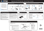
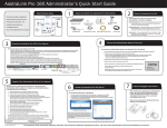
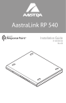
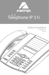
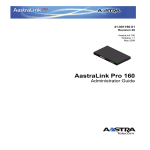
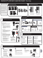
AastraLink Pro 160 User’s Quick Start Guide - Phone Setup
Supported Aastra SIP IP Phone Models
Optional Aastra IP Phone Expansion Modules
This quick start guide is designed to
help you quickly set up and use your
IP phone in an AastraLink Pro 160
Services
Save
Del
35i
Swap
Hold
Redial
35i
Goodbye
Hold
Redial
Options
network. The complete documentation
Conf
Xfer
53i
51i
set is available online at:
55i
L3
L2
L1
1
2 ABC
4 GHI
Options
3 DEF
1
2 ABC
3 DEF
5 JKL
6 MNO
4 GHI
5 JKL
6 MNO
7 PQRS 8 TUV
9 WXYZ
7 PQRS 8 TUV
9 WXYZ
*
#
*
#
0
Xfer
Icom
Conf
L1
http://www.aastratelecom.com/support
9143i
Goodbye
0
Xfer
Services
L2
Icom
Conf
L4
L3
L1
9480i
Services
L2
L3
L4
9480i CT
536M
560M
Provides up to 36 additional softkeys
to the 53i, 55i, 57i, and 57i CT
57i
Provides up to 60 additional softkeys
to the 55i, 57i, and 57i CT
57i CT
SIP IP Phone Piece Parts
1
All models have these:
Install Your Phone on a Desktop or a Wall
asdassa
asdadsda
NOTE: Before installing the phone on the desk, connect the handset cord to the handset;
connect the other end of the cord into the handset jack on the back of the phone.
Figure D
(5i Series Phones)
1. Attach the stand by inserting the tabs on the stand (marked with o ) into the slots
on the bottom of the phone. For a higher viewing angle, use the slots marked n .
For a lower viewing angle, use the slots marked m .
2. Push the stand towards the phone until it snaps into place. (See Figure C).
Base Legs
Figure E
(9143i, 9480i, 9480i CT Phones)
2
To install the phone on a wall:
NOTE: Before installing the phone on the wall, connect the handset cord to the handset;
connect the other end of the cord into the handset jack on the back of the phone. Use
steps 3 and 4 to connect all other cables to the phone. If you have a phone wall plate with
pegs already installed on your wall, skip steps 1 and 2. Refer to Figures D and E.
To install the cordless handset:
1. Attach the charging cradle power adapter to the
charging cradle and plug the other end into a
non-switched AC outlet. (Figure F)
2. Turn the cordless handset face down, remove the
back cover, and install the battery. (Figure G)
Replace cover.
3. (optional) Clip the belt clip onto the back of the phone.
Ethernet
Cable
Power Adapter
The 5i Models also have these:
Figure C
9143i, 9480i, 9480i CT Phones
3
Mounting Template
and Hardware
Handset Handset
Cord
5i Series Phones
Attach each leg to the back of the phone by inserting the tabs on the leg into the
slots on the bottom of the phone. There are three pairs of leg slots on each corner
of the phone; each leg uses two pairs of slots when attached. (See Figure A)
There are a total of 4 viewing angles (by reversing the legs, the incline on the phone
can be changed). (See Figure B).
1. Use the wall mount drilling template to locate and mark the position
for the mounting screws on the wall.
2. Drill the holes and insert the mounting screws (insert the wall anchors
before inserting the mounting screws if required).
3. Coil the cables into the spaces provided on the back of the phone.
4. Connect the Ethernet cable to the wall network jack.
5. Place the wall mount holes on the back of the phone over the screw
heads on the wall and pull down to lock the phone in.
Wall Mount
Drilling Template
Figure B
Figure A
To install the phone on a desk:
The 9143i, 9480i, and 9480i CT Models also have these:
Figure F
Figure G
A
Small Programmable
Key Card (53i)
Base Stand
Programmable Key Card
and Plastic Lens (33i only)
Number Card
and Lens
The CT Models also have these:
Power Adapter
(for charging cradle)
Large Programmable
Key Card (55i)
Belt Clip
(for cordless
handset)
Battery
(for handset)
Charging Cradle
(for cordless
handset)
Identify Your Network Installation Option
Phone Powered by Inline
Power from the Network
For Ethernet networks
that supply in-line power to
the phone (IEEE 802.3af):
- Use the Ethernet cable (supplied)
to connect from the phone
directly to the network.
- No 48v AC power adapter
required.
B
Phone Powered by
48V AC Power Adapter
C
(Optional) Phone Powered
by PoE Power Injector
For Ethernet networks that
DO NOT supply power to the phone:
For Ethernet networks that DO NOT
supply power to the phone:
- Use the 48V AC Power Adapter
to connect from the DC power port
on the phone to a power source.
- Use the Ethernet cable (supplied)
to connect from the phone to a
network jack.
- Use a Power over Ethernet (PoE) NOTE: The optional PoE and Ethernet
cable are available from your Aastra
power injector.
dealer as optional accessories
- Use the Ethernet cable (supplied) (p/n D0023-0031-00-00 and
to connect from the phone to the p/n D0061-0065-00-00, respectively).
PoE power injector.
- Use an additional Ethernet cable
from the PoE to the Network jack (not supplied).
Connect Your Phone to the AastraLink Pro 160 Network
A
B
5i Series Phones
1. Connect the supplied Ethernet cable
to the l port (on 9143i, 9480i, and
9480i CT phones) the LAN port (on 5i phones).
2. Connect the other end of the
Ethernet cable to the Ethernet
hub/switch or the network jack.
NOTE: If your Ethernet network DOES NOT
provide power to the phone (either from the
switch, or using an inline power injector),
you must use the supplied 48v AC adapter
to power the phone. Connect the 48v adapter
cable into the phone’s power connector
and
plug the adapter into an AC power source.
41-001134-04 REV 00
To Network
9143i, 9480i, 9480i CT Phones
1. If you already have a network device, such as your computer,
connected to the Network Jack where you are installing the
phone, you will need to temporarily disconnect it from the
Network Jack.
k WARNING: This will disconnect your network connection.
2. Connect the Ethernet cable from the phone to the Network Jack.
C
5i Series Phones
Reconnect the cable previously removed
in step "B" to the back of the phone
marked with ; (9143i, 9480i, 9480i CT phones)
or PC (5i Series phones).
To Other
Network Device
Other Network Devices
9143i, 9480i, 9480i CT Phones
NOTE: The phone begins the startup process when power is first connected.
To Network
To Other
Network Device
1
AastraLink Pro 160 User’s Quick Start Guide - Account Registration
1
Register Your Phone on the AastraLink Pro 160 Network
Your system administrator has
installed an AastraLink Pro 160 on your
IP phone network.
When power is first connected, the phone begins a startup sequence and registration process.
This quick-start procedure describes
The phone checks for new configuration and firmware updates from the AastraLink Pro 160.
If a new update is found, the phone displays the update it is installing (either “Updating Config” or “New Firmware”).
This may take a few moments while the configuration server downloads the latest updates.
how to register your IP phone with the
AastraLink Pro 160. When you complete
WARNING: Do not unplug or remove power from the phone while it is checking and installing firmware.
this procedure, your phone will
Proceed to the following steps to complete the registration process.
operate on your network,
Enter First Name
Enter your first name and press <Enter>.
Register User Name
Enter First Name
Bob
60%
Checking for Firmware
Do not unplug phone!
ready to make and receive calls.
2
3
Enter Last Name
Register User
Enter Password
Enter a password and press <Enter>.
Register User
Enter Last Name
Jones
ABC
Dot
Backspace
4
Enter Email Address (Optional)
Enter your email address and press <Enter>.
Enter your last name and press <Enter>.
Register User
Enter Email Address
[email protected]
Enter
Back
ABC
Dot
Backspace
Enter
ABC
Dot
Backspace
Enter Password
*****
Enter
Back
Backspace
NOTE: You can skip this step and enter the
email address later using the AastraLink Web UI.
Enter
Back
NOTE: Record your password below for
future reference.
User
Password:
5
AastraLink Pro 160 IP Address
Your IP phone reboots. When startup is
complete, your Phone UI displays the
IP address of the AastraLink Pro 160 device.
6
7
Idle Screen
To complete the registration process, press <Exit>.
The IP phone idle screen appears. This screen
displays the user name, date, and the set of
default softkeys configured for your phone.
Your phone’s registered extension number
appears in the upper right hand corner.
Visit
http://10.20.50.135
for more options
To access the AastraLink Pro 160 Web UI:
1. Enter the IP address of the AastraLink Pro 160 in your Web browser. For example, http://10.20.50.135.
2. In the Login window, enter your User extension and the password chosen during registration (in Step 4).
3. Select <Login> to view the AastraLink Pro 160 Web UI Main Menu. The current AastraLink Pro 160 status displays
in the lower left corner of the Main Menu window.
201 - B Jones
L1
Exit
Access the AastraLink Pro 160 Web UI
May 1 10:15 am
NOTE: Record the IP address below for
future reference. You will need to enter it
into your Web browser for accessing the
AastraLink Web UI.
AastraLink Pro 160
IP Address:
41-001134-04 Rev 00
DND
Forward
Directory
Vmail
ParkCall
More
NOTE: For more information about
configuring the softkeys on your phone,
see the AastraLink Pro 160 User Guide.
AastraLink Pro Login Screen
Refer to the AastraLink 160 User’s Guide
for more information about operating your
IP phone.
AastraLink Pro Web UI Main Menu
For User Guides, Regulatory information, and Conformance Statements regarding this product, refer to the online documentation at http://www.aastratelecom.com/support.
2