1
2008
Air-Conditioners
TECHNICAL & SERVICE MANUAL
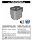
Models
PEFY-P06NMSU-E, PEFY-P08NMSU-E
PEFY-P12NMSU-E, PEFY-P15NMSU-E
PEFY-P18NMSU-E, PEFY-P24NMSU-E
For use with R410A & R22
Safety Precautions
Read before installation and performing electrical work
Thoroughly read the following safety precautions prior to installation.
Observe these safety precautions for your safety.
This equipment may have adverse effects on the equipment on the same power supply system.
Contact the local power authority before connecting to the system.
Symbol explanations
WARNING
This symbol indicates that failure to follow the instructions exactly as stated poses the risk of serious injury or death.
CAUTION
This symbol indicates that failure to follow the instructions exactly as stated poses the risk of serious injury or damage to the unit.
Indicates an action that must be avoided.
Indicates important instructions.
Indicates a parts that requires grounding.
Indicates that caution must be taken with rotating parts. (This symbol is on the main unit label.) <Color: Yellow>
Indicates that the parts that are marked with this symbol pose a risk of electric shock. (This symbol is on the main
unit label.) <Color: Yellow>
WARNING
Carefully read the labels affixed to the main unit.
WARNING
Ask your dealer or a qualified technician to install the unit.
Do not make any modifications or alterations to the unit.
Consult your dealer for repair.
Improper installation by the user may result in water leakage, electric shock, or fire.
Improper repair may result in water leakage, electric shock,
or fire.
Properly install the unit on a surface that can withstand its
weight.
Do not touch the heat exchanger fins with bare hands.
The fins are sharp and pose a risk of cuts.
Unit installed on an unstable surface may fall and cause injury.
In the event of a refrigerant leak, thoroughly ventilate the
room.
Only use specified cables. Securely connect each cable so
that the terminals do not carry the weight of the cable.
If gaseous refrigerant leaks out and comes in contact with
an open flame, toxic gases will be generated.
Improperly connected cables may produce heat and start a
fire.
Properly install the unit according to the instructions in the
Installation Manual.
Take appropriate safety measures against wind gusts and
earthquakes to prevent the unit from toppling over.
Improper installation may result in water leakage, electric
shock, or fire.
Improper installation may cause the unit to topple over and
cause injury or damage to the unit.
Have all electrical work performed by an authorized electrician according to the local regulations and the instructions
in this manual. Use a dedicated circuit.
Only use accessories (i.e., air cleaners, humidifiers, electric
heaters) recommended by Mitsubishi Electric.
Insufficient power supply capacity or improper installation
of the unit may result in malfunctions of the unit, electric
shock, or fire.
HWE08010
i
GB
WARNING
Keep electrical parts away from water.
Consult your dealer or a qualified technician when moving
or reinstalling the unit.
Wet electrical parts pose a risk of electric shock, smoke, or
fire.
Improper installation may result in water leakage, electric
shock, or fire.
Securely attach the control box cover.
After completing the service work, check for a refrigerant
leak.
If the cover is not installed properly, dust or water may infiltrate and pose a risk of electric shock, smoke, or fire.
If leaked refrigerant is exposed to a heat source, such as a
fan heater, stove, or electric grill, toxic gases will be generated.
Only use the type of refrigerant that is indicated on the unit
when installing or relocating the unit.
Infiltration of any other types of refrigerant or air into the unit
may adversely affect the refrigerant cycle and may cause
the pipes to burst or explode.
Do not try to defeat the safety features of the unit.
Forced operation of the pressure switch or the temperature
switch by defeating the safety features for these devices, or
the use of accessories other than the ones that are recommended by Mitsubishi Electric may result in smoke, fire, or
explosion.
When installing the unit in a small space, take appropriate
precautions to prevent leaked refrigerant from reaching the
limiting concentration.
Leaked refrigerant gas will displace oxygen and may cause
oxygen starvation. Consult your dealer before installing the
unit.
Consult your dealer for proper disposal method.
Do not use a leak detection additive.
Precautions for handling units for use with R410A
CAUTION
Do not use the existing refrigerant piping.
Only use R410A.
A large amount of chlorine that may be contained in the residual refrigerant and refrigerator oil in the existing piping
may cause the refrigerator oil in the new unit to deteriorate.
The use of other types of refrigerant that contain chloride
may cause the refrigerator oil to deteriorate.
Use a vacuum pump with a check valve.
Use refrigerant piping materials made of phosphorus deoxidized copper. Keep the inner and outer surfaces of the
pipes clean and free of such contaminants as sulfur, oxides,
dust, dirt, shaving particles, oil, and moisture.
If a vacuum pump that is not equipped with a check valve is
used, the vacuum pump oil may flow into the refrigerant cycle and cause the refrigerator oil to deteriorate.
Contaminants in the refrigerant piping may cause the refrigerator oil to deteriorate.
Prepare tools for exclusive use with R 410A. Do not use the
following tools if they have been used with the conventional
refrigerant: gauge manifold, charging hose, gas leak detector, check valve, refrigerant charge base, vacuum gauge,
and refrigerant recovery equipment.
Store the piping materials indoors, and keep both ends of
the pipes sealed until immediately before brazing. (Keep elbows and other joints wrapped in plastic.)
If the refrigerant or the refrigerator oil that may be left on these
tools are mixed in with R410A, it may cause the refrigerator oil
in the new system to deteriorate.
Infiltration of water may cause the refrigerator oil to deteriorate.
Leak detectors for conventional refrigerants will not detect an
R410A leak because R410A is free of chlorine.
Infiltration of dust, dirt, or water into the refrigerant system
may cause the refrigerator oil to deteriorate or cause the
compressor to malfunction.
Use a small amount of ester oil, ether oil, or alkyl benzene
to coat flares and flanges.
Do not use a charging cylinder.
Infiltration of a large amount of mineral oil may cause the refrigerator oil to deteriorate.
If a charging cylinder is used, the composition of the refrigerant
in the cylinder will change and become unsuitable for use.
Charge the system with refrigerant in the liquid phase.
Exercise special care when handling tools for use with R410A.
If gaseous refrigerant is drawn out of the cylinder first, the
composition of the remaining refrigerant in the cylinder will
change and become unsuitable for use.
HWE08010
Infiltration of dust, dirt, or water into the refrigerant system
may cause the refrigerator oil to deteriorate.
ii
GB
Precautions for PAC-YU25HT (Optional parts)
WARNING
Stop the operation if any malfunction occurs.
Keep the heater clean to keep the indoor unit from sucking
in accumulated dust on the heater.
If malfunction occurs (burning smell, etc.) stop the operation and turn off the power supply. Contact your dealer or
technical representative. If the controller continues to operate after a malfunction occurs, this may cause damage,
electric shock or fire.
Dust particles that enter the indoor unit may cause fire.
When air conditioner and heater are configured to perform
an interlocked operation, do not use any other type of cables except this external heater adapter (PAC-YU25HT).
Do not turn on the main power until installation has been
completed.
The use of any other type of cables may result in malfunctions or fire.
Doing so may result in electric shock or fire.
Do not build a heater into the indoor unit.
Leave sufficient space between heater and indoor unit to allow for air movement to prevent the indoor unit from overheating.
Doing so may result in fire.
If they are installed too closely and the indoor unit temperature exceeds 40°C, malfunctions or fire may result.
CAUTION
Do not install in any place exposed to flammable gas leakage.
Do not install in any steamy place such a bathroom or kitchen.
Flammable gases accumulated around the body of PACYU25HT may cause an explosion.
Avoid any place where moisture is condensed into dew.Doing so may cause an electric shock or malfunction.
Do not use in any special environment.
Do not wash with water.
Using in any place exposed to oil (including machine oil),
steam and sulfuric gas may deteriorate the performance
significantly or give damage to the component parts.
Doing so may cause an electric shock or malfunction.
Do not install in any place at a temperature of more than
40°C (104°F) or less than 0°C (32°F) or exposed to direct
sunlight.
Do not install in any place where acidic or alkaline solution
or special spray are often used.
Doing so may cause an electric shock or malfunction.
HWE08010
iii
GB
HWE08010
iv
GB
CONTENTS
I Features
[1] Features.................................................................................................................................... 1
II Components and Functions
[1] Components and Functions...................................................................................................... 2
III Specfications
[1] Specifications............................................................................................................................ 4
1.Specfications .......................................................................................................................... 4
2.Electrical component specifications........................................................................................ 6
IV Outlines and Dimensions
[1] Outlines and Dimensions.......................................................................................................... 7
V Wiring Diagram
[1] Wiring Diagram ......................................................................................................................... 8
VI Refrigerant System Diagram
[1] Refrigerant system diagram...................................................................................................... 9
VII Microprocessor Control
[1] Microprocessor Control........................................................................................................... 10
1.Cool operation ...................................................................................................................... 10
2.Dry operation ........................................................................................................................ 11
3.Fan operation........................................................................................................................ 12
4.Heat operation ...................................................................................................................... 13
5.Auto operation [Automatic cool / heat change over operation] ............................................. 14
6.When unit is stopped control mode ...................................................................................... 15
7.Heater control ....................................................................................................................... 15
VIII Troubleshooting
[1] Troubleshooting ...................................................................................................................... 19
1.Check methods..................................................................................................................... 19
2.DC fan motor (fan motor/indoor control board)..................................................................... 23
3.Address switch setting .......................................................................................................... 24
4.Voltage test points on the control board ............................................................................... 25
5.Dipswitch setting (Factory setting)........................................................................................ 26
IX Disassembly Procedure
[1] Disassembly Procedure.......................................................................................................... 29
1.Control box ........................................................................................................................... 29
2.Thermistor (Intake air) .......................................................................................................... 30
3.Drainpan ............................................................................................................................... 31
4.Thermistor (Gas pipe) (Liquid pipe) ...................................................................................... 32
5.Fan and fan motor ................................................................................................................ 33
6.Bearing ................................................................................................................................. 34
7.Heat exchanger .................................................................................................................... 35
HWE08010
GB
HWE08010
GB
[ I Features ]
I Features
[1] Features
Model
HWE08010
Cooling capacity/Heating capacity
BTU/h
kW
PEFY-P06NMSU-E
6000/6700
1.8/2.0
PEFY-P08NMSU-E
8000/9000
2.3/2.6
PEFY-P12NMSU-E
12000/13500
3.5/4.0
PEFY-P15NMSU-E
15000/17000
4.4/5.0
PEFY-P18NMSU-E
18000/20000
5.3/5.9
PEFY-P24NMSU-E
24000/27000
7.0/7.9
-1-
GB
[ II Components and Functions ]
II Components and Functions
[1] Components and Functions
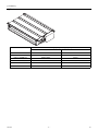
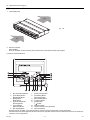
1. Indoor (Main) Unit
(A)
(A)
Air
(A)
2. Remote Controller
[PAR-21MAA]
Once the operation mode is selected, the unit will remain in the selected mode until changed.
(1) Remote Controller Buttons
1
2
[Set Temperature] Button
7
[Vane Control] Button
[Timer Menu] Button
8
[Ventilation] Button
[Monitor/Set] Button
[Operation] Button
3 [Mode] Button
9
[Check/Clear] Button
[Back] Button
10 [Test Run] Button
4 [Timer On/Off] Button
11 [Filter] Button
[Set Day] Button
[ ] Button
5 [Louver] Button
12 [ON/OFF] Button
[Operation] Button
13 Position of built-in room thermistor
6 [Fan Speed] Button
14 [Set Time] Button
Keep the remote controller out of direct sunlight to ensure accurate measurement of room temperature.
The thermistor at the lower right-hand section of the remote controller must be free from obstructions to ensure accurate measurement of room temperature.
HWE08010
-2-
GB
[ II Components and Functions ]
(2) Remote Controller Display
A
Current time/Timer time
I
Louver swing
B
Centralized control indicator
J
Ventilation
C
Timer OFF indicator
K
Filter sign
D
Timer mode
L
Sensor position
E
Operation mode display:
FAN,
HEAT
M
Room temperature
F
Function Lock indicator
N
Vane setting
G
Preset temperature
O
Fan speed
H
Power indicator
HWE08010
COOL,
DRY,
AUTO,
-3-
GB
[ III Specfications ]
III Specfications
[1] Specifications
1. Specfications
Model
PEFY-P06NMSU-E
PEFY-P08NMSU-E
Power source
PEFY-P12NMSU-E
PEFY-P15NMSU-E
1-phase 208/230V 60Hz
Cooling capacity
*1
BTU / h
6,000
8,000
12,000
(Nominal)
*1
kW
1.8
2.3
3.5
4.4
kW
0.05/0.05
0.06/0.06
0.07/0.07
0.07/0.07
A
0.42/0.41
0.51/0.49
0.56/0.53
0.57/0.55
6,700
9,000
13,500
17,000
Power input
Current input
15,000
Heating capacity
*2
BTU / h
(Nominal)
*2
kW
2.0
2.6
4.0
5.0
Power input
kW
0.03/0.03
0.04/0.04
0.05/0.05
0.05/0.05
Current input
A
0.32/0.31
0.41/0.39
0.46/0.43
0.47/0.45
External finish
Galvanized
External dimension H x W x D
in.
mm
Net weight
7-7/8 x 31-1/8 x 27-9/16
7-7/8 x 31-1/8 x 27-9/16
7-7/8 x 31-1/8 x 27-9/16
7-7/8 x 39 x 27-9/16
200 x 790 x 700
200 x 790 x 700
200 x 790 x 700
200 x 990 x 700
42(19)
42(19)
46(20)
54(24)
lbs (kg)
Heat exchanger
FAN
Cross fin(Aluminium fin and copper tube)
Type x Quantity
External
in.WG
static press
Pa
in.WG
Pa
Sirocco fan x 2
Sirocco fan x 2
Sirocco fan x 2
Sirocco fan x 3
0.02-0.06-0.14-0.20
(208V)
0.02-0.06-0.14-0.20
(208V)
0.02-0.06-0.14-0.20
(208V)
0.02-0.06-0.14-0.20
(208V)
5-15-35-50
5-15-35-50
5-15-35-50
5-15-35-50
0.02-0.06-0.14-0.20
(230V)
0.02-0.06-0.140.20(230V)
0.02-0.06-0.140.20(230V)
0.02-0.06-0.140.20(230V)
5-15-35-50
5-15-35-50
5-15-35-50
5-15-35-50
Motor type
DC brushless motor
Motor output
kW
0.096
0.096
Driving mechanism
0.096
0.096
282-335-388
Direct-driven
Airflow rate
cfm
(Low-Mid-High)
m3 / min
L/s
176-212-247
194-247-317
211-282-370
5-6-7
5.5-7-9
6-8-10.5
8-9.5-11
83-100-117
91-116-150
100-133-175
133-158-183
Sound pressure level
dB <A>
22-24-28 (208V)
23-26-30 (208V)
23-28-35 (208V)
28-30-33 (208V)
(Low-Mid-High)
dB <A>
22-24-28 (230V)
23-26-30 (230V)
23-28-35 (230V)
28-30-33 (230V)
(measured in anechoic room)
dB <A>
-
-
-
-
Insulation material
Polystyrene foam,Polyethylene foam,Urethane foam
Air filter
PP Honeycomb fabric (washable)
Protection device
Fuse
Refrigerant control device
LEV
Connectable outdoor unit
Diameter of
Liquid
(R410A)
Gas
R410A,R22 CITY
MULTI
R410A,R22 CITY
MULTI
1/4 (6.35) Brazed
1/4 (6.35) Brazed
1/4 (6.35) Brazed
1/4 (6.35) Brazed
1/4 (6.35) Brazed
1/4 (6.35) Brazed
1/4 (6.35) Brazed
1/4 (6.35) Brazed
(R410A)
1/2 (12.7) Brazed
1/2 (12.7) Brazed
1/2 (12.7) Brazed
1/2 (12.7) Brazed
1/2 (12.7) Brazed
1/2 (12.7) Brazed
1/2 (12.7) Brazed
1/2 (12.7) Brazed
O.D. 1-1/4(32)
O.D. 1-1/4(32)
O.D. 1-1/4(32)
O.D. 1-1/4(32)
(O.D.)
in. (mm)
in. (mm)
(R22 )
Diameter of drain pipe
Drawing
R410A,R22 CITY
MULTI
(R22 )
refrigerant
pipe
*3
in. (mm)
External
WKB94L522
Wiring
WKB94L523
Refrigerant cycle
Standard
Document
attachment
Accessory
Optional
External heater adaptor
Installation Manual, Instruction Book
Drain hose (flexible joint)
PAC-YU25HT
PAC-YU25HT
PAC-YU25HT
PAC-YU25HT
parts
Remark
Installation
Note :
Indoor :
Outdoor :
Pipe length :
Level difference :
Details on foundation work, duct work, insulation work, electrical wiring, power source switch, and other
items shall be referred to the Installation Manual.
*1 Nominal cooling conditions
*2 Nominal heating conditions
80degF D.B. / 67degF W.B.
70degF D.B.
kcal/h = kW x 860
(26.7degC D.B. / 19.4degC W.B.)
(21.1degC D.B.)
BTU/h = kW x 3,412
95degF D.B.
47degF D.B. / 43degF W.B.
cfm = m3/min x 35.31
(35degC D.B.)
(8.3degC D.B. / 6.1degC W.B.)
lbs = kg / 0.4536
25 ft. (7.6 m)
25 ft. (7.6 m)
0 ft. (0 m)
0 ft. (0 m)
*3 PUHY-THMU,PURY-THMU,PUHY-YHMU,PURY-YHMU,PUMY-NHMU
Unit convertor
*Above specification data is
subject to rounding variation.
*The external static pressure is set to 15 Pa at factory shipment.
*Due to continuing improvement, above specification may be subject to change without notice.
HWE08010
-4-
GB
[ III Specfications ]
Model
PEFY-P18NMSU-E
PEFY-P24NMSU-E
18,000
24,000
Power source
1-phase 208/230V 60Hz
Cooling capacity
*1
(Nominal)
*1
Power input
Current input
BTU / h
kW
5.3
7.0
kW
0.09/0.09
0.12/0.12
A
0.74/0.70
0.98/0.93
20,000
27,000
Heating capacity
*2
BTU / h
(Nominal)
*2
kW
5.9
7.9
Power input
kW
0.07/0.07
0.10/0.10
Current input
A
0.64/0.60
0.88/0.83
External dimension H x W x D
in.
7-7/8 x 39 x 27-9/16
7-7/8 x 46-7/8 x 27-9/16
200 x 990 x 700
200 x 1190 x 700
Net weight
lbs (kg)
External finish
Galvanized
mm
54(24)
62(28)
Heat exchanger
FAN
Cross fin(Aluminium fin and copper tube)
Type x Quantity
External
in.WG
static press
Pa
Sirocco fan x 3
Sirocco fan x 4
0.02-0.06-0.14-0.20
(208V)
0.02-0.06-0.14-0.20
(208V)
5-15-35-50
5-15-35-50
0.02-0.06-0.14-0.20
(230V)
0.02-0.06-0.140.20(230V)
Pa
5-15-35-50
5-15-35-50
kW
0.096
0.096
cfm
353-441-529
423-565-706
in.WG
Motor type
DC brushless motor
Motor output
Driving mechanism
Airflow rate
(Low-Mid-High)
Direct-driven
m3 / min
L/s
10-12.5-15
12-16-20
167-208-250
200-267-333
Sound pressure level
dB <A>
30-34-37 (208V)
30-35-40 (208V)
(Low-Mid-High)
dB <A>
30-34-37 (230V)
30-35-40 (230V)
(measured in anechoic room)
dB <A>
-
-
Insulation material
Polystyrene foam,Polyethylene foam,Urethane foam
Air filter
PP Honeycomb fabric (washable)
Protection device
Fuse
Refrigerant control device
LEV
Connectable outdoor unit
Diameter of
Liquid
(R410A)
refrigerant
pipe
Gas
in. (mm)
R410A,R22 CITY
MULTI
1/4 (6.35) Brazed
3/8 (9.52) Brazed
(R22 )
3/8 (9.52) Brazed
3/8 (9.52) Brazed
(R410A)
1/2 (12.7) Brazed
5/8 (15.88) Brazed
5/8 (15.88) Brazed
5/8 (15.88) Brazed
O.D. 1-1/4(32)
O.D. 1-1/4(32)
(O.D.)
in. (mm)
(R22 )
Diameter of drain pipe
Drawing
R410A,R22 CITY
MULTI
in. (mm)
External
WKB94L522
Wiring
WKB94L523
Refrigerant cycle
Standard
Document
attachment
Accessory
Optional
External heater adaptor
Installation Manual, Instruction Book
Drain hose (flexible joint)
PAC-YU25HT
PAC-YU25HT
parts
Remark
Installation
Note :
Indoor :
Outdoor :
Pipe length :
Level difference :
Details on foundation work, duct work, insulation work, electrical wiring, power source switch, and other
items shall be referred to the Installation Manual.
*1 Nominal cooling conditions
*2 Nominal heating conditions
80degF D.B. / 67degF W.B.
70degF D.B.
kcal/h = kW x 860
(26.7degC D.B. / 19.4degC W.B.)
(21.1degC D.B.)
BTU/h = kW x 3,412
95degF D.B.
47degF D.B. / 43degF W.B.
cfm = m3/min x 35.31
(35degC D.B.)
(8.3degC D.B. / 6.1degC W.B.)
lbs = kg / 0.4536
25 ft. (7.6 m)
25 ft. (7.6 m)
0 ft. (0 m)
0 ft. (0 m)
*The external static pressure is set to 15 Pa at factory shipment.
Unit convertor
*Above specification data is
subject to rounding variation.
*Due to continuing improvement, above specification may be subject to change without notice.
HWE08010
-5-
GB
[ III Specfications ]
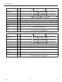
2. Electrical component specifications
Component
Symbol
PEFY-P06NMSU-E
Room temperature
thermistor
TH21
Resistance 0°C[32°F]/15k , 10°C[50°F]/9.6k , 20°C[68°F]/6.3k , 25°C[77°F]/5.4k ,
30°C[86°F]/4.3k , 40°C[104°F]/3.0k
Liquid pipe thermistor
TH22
Resistance 0°C[32°F]/15k , 10°C[50°F]/9.6k , 20°C[68°F]/6.3k , 25°C[77°F]/5.4k ,
30°C[86°F]/4.3k , 40°C[104°F]/3.0k
Gas pipe thermistor
TH23
Resistance 0°C[32°F]/15k , 10°C[50°F]/9.6k , 20°C[68°F]/6.3k , 25°C[77°F]/5.4k ,
30°C[86°F]/4.3k , 40°C[104°F]/3.0k
Fuse
FUSE
250V 6.3A
Fan motor
PEFY-P12NMSU-E
8-pole, Output 96W SIC-70CW-D8114-1
Linear expansion valve
LEV
Power supply terminal
block
TB2
Transmission terminal
block
TB5
TB15
Drain float switch
PEFY-P08NMSU-E
12VDC Stepping motor drive port diameter ø3.2 (0~2000 pulse)
(L1, L2, G) 330V 30A
(1, 2), (M1, M2, S) 250V 20A
DS
Open/short detection
Initial contact resistance 500 m
Component
Symbol
Room temperature
thermistor
TH21
Resistance 0°C[32°F]/15k , 10°C[50°F]/9.6k , 20°C[68°F]/6.3k , 25°C[77°F]/5.4k ,
30°C[86°F]/4.3k , 40°C[104°F]/3.0k
Liquid pipe thermistor
TH22
Resistance 0°C[32°F]/15k , 10°C[50°F]/9.6k , 20°C[68°F]/6.3k , 25°C[77°F]/5.4k ,
30°C[86°F]/4.3k , 40°C[104°F]/3.0k
Gas pipe thermistor
TH23
Resistance 0°C[32°F]/15k , 10°C[50°F]/9.6k , 20°C[68°F]/6.3k , 25°C[77°F]/5.4k ,
30°C[86°F]/4.3k , 40°C[104°F]/3.0k
Fuse
FUSE
250V 6.3A
Fan motor
LEV
Power supply terminal
block
TB2
Transmission terminal
block
TB5
TB15
HWE08010
PEFY-P18NMSU-E
PEFY-P24NMSU-E
8-pole, Output 96W SIC-70CW-D896-2
Linear expansion valve
Drain float switch
PEFY-P15NMSU-E
or less
DS
12VDC Stepping motor drive port diameter ø3.2 (0~2000 pulse)
(L1, L2, G) 330V 30A
(1, 2), (M1, M2, S) 250V 20A
Open/short detection
Initial contact resistance 500 m
-6-
or less
GB
57(2-1/4)
70
(2-25/32)
270 (10-21/32)
700 (27-9/16)
677 (26-21/32)
25(1)
(35-7/16) (37-1/2) (39-5/16) (33-7/8)
1100 1152 1198 1060
PEFY-P24NMSU-E (43-5/16)
(45-3/8) (47-3/16) (41-3/4)
PEFY-P18NMSU-E
B
C
D
Model
A
700 752 798 660
PEFY-P06,08,12NMSU-E (27-9/16)
(29-5/8) (31-7/16) (26)
PEFY-P15NMSU-E 900 952 998 860
11
9
7
E
(26)
860
(23-5/8) (31-1/2)
1000
800
H
1060
(39-3/8) (47-1/4) (41-3/4)
(31-1/2) (39-3/8) (33-7/8)
660
G
800
F
600
1000 1200
23 (29/32)
9
7
5
J
L
N
1039 990
790
(33-1/16) (31-1/8)
M
839
900
(35-7/16) 24
1239 1190
(48-25/32) (46-7/8)
(27-9/16) 20 (40-29/32) (39)
700
(19-11/16) 16
K
500
ø15.88(5/8)
*1 ø12.7(1/2) *1
*2 ø15.88(5/8) *2
ø12.7(1/2)
1 Gas pipe
(131
2)
( 1 7 450
-23
/32
)
0
45 2)
00
3/3 an 3 /16)
2
3
th
(17 ore 11-1
(
M
)
7
77 9/32
-1 Access
0
3
(
door
Drain hose (I.D.ø32(1-1/4))
<accessory>
Less than 300
(11-13/16)
Make the access door at the appointed
position properly for service maintenance.
Ceiling surface Access door
Required space for service and maintenance
/32 50~1
~ 5 50
-29
/32
)
50
(1
G -31/3
175±5(6-29/32±7/32)
(Actual length)
Note2
)
/32
31
(150
Knockout hole ø27(1-3/32)
(Transmission wiring)
Air filter
37(1-15/32)
100(3-15/16)
157.5 (6-7/32)
37(1-15/32)
ø9.52(3/8)
ø6.35(1/4)
ø9.52(3/8)
ø6.35(1/4)
*1:R410A outdoor unit
*2:R22 outdoor unit
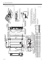
Note 1. Use M10 screw for the Suspension bolt (field supply).
2. Keep the service space for the maintenance at the bottom.
3. This chart indicates for PEFY-P15·18NMSU-E models,which
has 3 fans.
PEFY-P06~12NMSU-E models have 2 fans.
PEFY-P24NMSU-E model have 4 fans.
mm(in.) 4. In case of the inlet duct is used,remove the air filter(supply with
2 Liquid pipe
the unit), then install the filter(field supply) at suction side.
Knockout hole ø27(1-3/32)
(Power source wiring)
88 (3-15/32)
Terminal bed(Power source)
Terminal bed(Transmission)
Drain pipe(O.D.ø32(1-1/4))
(Spontaneous draining)
Control box
2x2-ø2.9(1/8)
2 Refrigerant piping
1 Refrigerant piping
brazing connection (gas) brazing connection (liquid)
116
(4-19/32)
23(29/32)
10(13/32)
Drain pump
10 (13/32)
625 (Suspension bolt pitch)
(24-5/8)
Drain pipe(O.D.ø32(1-1/4))
49
(1-15/16)
Air
inlet
48(1-29/32)
102 (4-1/32)
90
170 (6-23/32) (3-9/16)
200(7-7/8)
88(3-15/32)
L-ø2.9(1/8)
H
20 (13/16)
159(6-9/32)
Air
outlet
A
N
B (Suspension bolt pitch)
C
M
Suspension bolt hole 20 (13/16)
4-14x30(9/16x1-3/16) Slot
12 (1/2)
100(3-15/16)xJ=K
100(3-15/16)
12 (1/2)
2xE-ø2.9(1/8)
100 (3-15/16)
Drain pipe(O.D.ø32(1-1/4))
(Emergency draining)
More than 10
(13/32)
More than 20
(13/16)
15 (19/32)
D (Duct)
100(3-15/16)x(E-1)=F
100(3-15/16)
20 (13/16)
30 (1-3/16)
25 (1)
-7-
100
(3-15/16)
Less than 550
(21-21/32)
HWE08010
150(Duct)
(5-29/32) 23 (29/32)
345 (13-19/32)
[ IV Outlines and Dimensions ]
IV Outlines and Dimensions
[1] Outlines and Dimensions
1. PEFY-P06,08,12,15,18,24NMSU-E
Unit : mm(in)
GB
HWE08010
6 5 4
9 0 1
2
3
SW1
SW5
8
7
4
3
2
1
6 5 4
9 0 1
2
3
-8-
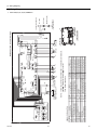
SYMBOL
I.B.
A.B.
TB2
TB5
TB15
FUSE
ZNR01,02
DSA
X1
CN24
CN27
NAME
Indoor controller board
Address board
Power source terminal bed
Transmission terminal bed
Transmission terminal bed
Fuse AC250V 6.3A
Varistor
Arrester
Aux. relay
Connector (Heater)
Connector (Damper)
SYMBOL EXPLANATION
8
7
6
5
4
3
2
1
CN82
SW14
(Connection No.)
SWC
0
EF 1 2
D
3
4
C
B
5
A
9 8 76
SWA SWB CN43
SW12
SW11
(2nd digit) (1st digit)
8
7
A.B.
2
TB15
CN51
LED2
SW4
CN90
SW2
FS
1234
1234
t°
CN4F
CN44
(Yellow) (Red)
CN24
CN27
SWE
OFF ON
TH22 TH23
t°
SW3
21
TH21
t°
12
LED1
CN20(Red)
DC310~340V
Rectify circuit
CNMF
SYMBOL
CN32
CN41
CN51
CN52
CN90
FS
CN4Y
TH21
TH22
TH23
SW2(I.B.)
NAME
Connector (Remote switch)
Connector (HA terminal-A)
Connector (Centrally control)
Connector (Remote indication)
Connector (Wireless)
Float switch
Connector
Thermistor (inlet air temp.detection)
Thermistor (piping temp.detection/liquid)
Thermistor (piping temp.detection/gas)
Switch (for capacity code)
SYMBOL
SW3(I.B.)
SW4(I.B.)
SWE(I.B.)
SW1(A.B.)
SW5(A.B.)
SW11(A.B.)
SW12(A.B.)
SW14(A.B.)
SWA(A.B.)
SWB(A.B.)
SWC(A.B.)
NAME
Switch (for mode selection)
Switch (for model selection)
Connector (emergency operation)
Switch (for mode selection)
Switch (for mode selection)
Switch (1st digit address set)
Switch (2nd digit address set)
Switch (connection No.set)
Switch (for static pressure selection)
Switch (for model selection)
Switch (for static pressure selection)
U
ZNR01
Fan motor
M
7654
CN2M
(Blue)
NOTE: 1.The wirings to TB2,TB5,TB15 shown in dotted line are field work.
2.Mark indicates terminal bed, connector.
3.Use copper supply wire.
LEV
M
CN41
CN42
(Red)
1234
TO OUTDOOR UNIT
TO MA REMOTE
BC CONTROLLER
CONTROLLER
REMOTE CONTROLLER
TB5
M1 M2 S(SHIELD) 1
CN52
CN4Y
CN81
(Red)
12345678
1
2
3 CN60
4
5
(Green)
6
1 CN3A
(Blue)
3
CN32
1
M
1~
3
1
(Blue)
5
1 CNP
X1
3
A.B.
I.B.
POWER SUPPLY
~ 208V/230V 60Hz
BREAKER (16A)
FUSE (16A)
PULL BOX
TO NEXT INDOOR UNIT
TB5 TB15 TB2
G
TB2
L1
L2
PARTS LOCATION
CONTROL BOX
Drainpump
FUSE
U
ZNR02
DSA
CND
(Black)
I.B.
INSIDE SECTION OF CONTROL BOX
[ V Wiring Diagram ]
V Wiring Diagram
[1] Wiring Diagram
1. PEFY-P06,08,12,15,18,24NMSU-E
GB
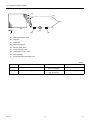
[ VI Refrigerant System Diagram ]
VI Refrigerant System Diagram
[1] Refrigerant system diagram
(A)
(B)
(G)
(D)
(C)
(H)
(F)
(E)
(I)
(A)
Gas pipe thermistor TH23
(B)
Gas pipe
(C)
Liquid pipe
(D)
Brazed connections
(E)
Strainer (#100 mesh)
(F)
Linear expansion valve
(G)
Liquid pipe thermistor TH22
(H)
Heat exchanger
(I)
Room temperature thermistor TH21
(E)
mm[in.]
Capacity
PEFY-P06,08,12,15NMSU-E
PEFY-P18NMSU-E
PEFY-P24NMSU-E
Gas pipe
ø12.7 [1/2]
R410A: ø12.7 [1/2]
R22: ø15.88 [5/8]
ø15.88 [5/8]
Liquid pipe
ø6.35 [1/4]
R410A: ø6.35 [1/4]
R22: ø9.52 [3/8]
ø9.52 [3/8]
HWE08010
-9-
GB
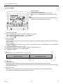
[ VII Microprocessor Control ]
VII Microprocessor Control
[1] Microprocessor Control
1. Cool operation
<How to operate>
1. Press POWER [ON/OFF] button.
2. Press the operation [Mode] button to display COOL.
3. Press the [Set Temperature] button to set the desired temperature.
TIME SUN MON TUE WED THU FRI SAT
TIMER
Hr
ON
AFTER
AFTER OFF
ERROR CODE
˚F˚C
˚F˚C
TEMP.
MENU
PAR-21MAA
MONITOR/SET
The set temperature changes 2°F when the [Set Temperature]
button is pressed one time. Cooling 67 to 87°F
WEEKLY
SIMPLE
AUTO OFF
ONLY1Hr.
BACK
FUNCTION
FILTER
ON/OFF
ON/OFF
FILTER
DAY
CHECK TEST
OPERATION
CLOCK
CLEAR
1. Termoregulating function
(1) Thermoregulating function (Function to prevent restarting for 3 minutes)
Room temperature
desired temperature + 2°F ···Thermo ON
Room temperature
desired temperature ···Thermo OFF
(2) Anti-freezing control
Detected condition :
When the liquid pipe temp. (TH22) is 32°F or less in 16 minutes from compressors start up, anti-freezing control starts and
the thermo OFF.
Released condition :
The timer which prevents reactivating is set for 3 minutes, and anti-freezing control is cancelled when any one of the following
conditions is satisfied.
1) Liquid pipe temp. (TH22) turns 50°F or above.
2) The condition of the thermo OFF has become complete by thermoregulating, etc.
3) The operation modes became mode other than COOL.
4) The operation stopped.
2. Fan
(1) By the remote controller setting (switch of 3 speeds+Auto)
Type
Fan speed notch
3 speeds + Auto type
[Low], [Med], [High], [Auto]
When [Auto] is set, fan speed is changed depending on the value of: Room temperature - Desired temperature
3. Drain pump
(1) Drain pump control
Always drain pump ON during the COOL and DRY mode operation. (Regardless of the thermo ON/ OFF)
When the operation mode has changed from the COOL or DRY to the others (including Stop), OFF the control after the drain
pump ON for 3 minutes.
(2) Float switch control
Float switch control judges whether the sensor is in the air or in the water by turning the float switch ON/OFF.
In the water : Detected that the float switch is ON for 15 seconds.
HWE08010
- 10 -
GB
[ VII Microprocessor Control ]
In the air : Detected that the float switch is OFF for 15 seconds.
Float SW
ON
OFF
15sec.
15sec.
In the water
15sec. 1min.30sec.
In the air
In the water
1min.30sec.
Drain pump
abnormal
Error
postponement
2. Dry operation
<How to operate>
1. Press POWER [ON/OFF] button.
2. Press the operation [Mode] button to display DRY.
3. Press the [Set Temperature] button to set the desired temperature.
TIME SUN MON TUE WED THU FRI SAT
TIMER
Hr
ON
AFTER
AFTER OFF
ERROR CODE
˚F˚C
˚F˚C
TEMP.
MENU
MONITOR/SET
PAR-21MAA
The set temperature changes 2°F when the [Set Temperature]
button is pressed one time. Dry 67 to 87°F
WEEKLY
SIMPLE
AUTO OFF
ONLY1Hr.
BACK
FUNCTION
FILTER
ON/OFF
ON/OFF
FILTER
DAY
CLOCK
CHECK TEST
OPERATION
CLEAR
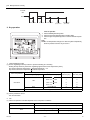
1. Termoregulating function
(1) Thermo regulating function (Function to prevent restarting for 3 minutes)
Setting the Dry thermo by the thermo regulating signal and the room temperature (TH21).
Dry thermo ON Room temperature desired temperature + 2°F
Dry thermo OFF Room temperature desired temperature
3 min. passed since starting operation
Room temperature
Thermo regulating signal
Room temperature (T1)
Dry thermo
ON time (min)
Dry thermo
OFF time (min)
T1
83°F
9
3
83°F > T1
79°F
7
3
79°F > T1
75°F
5
3
3
3
3
10
ON
Over 64°F
75°F > T1
OFF
Unconditional
Less than 64°F
Dry thermo OFF
(2) Frozen prevention control
No control function
2. Fan
(1) Indoor fan operation controlled depends on the compressor conditions.
Dry thermo
Fan speed notch
ON
[Low]
Excluding the following
Stop
Room temp. < 64°F
[Low]
OFF
HWE08010
- 11 -
GB
[ VII Microprocessor Control ]
Remote controller setting is not acceptable.
3. Drain pump
(1) Same control as COOL operation
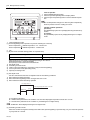
3. Fan operation
<How to operate>
1. Press POWER [ON/OFF] button.
2. Press the operation [Mode] button to display FAN.
TIME SUN MON TUE WED THU FRI SAT
TIMER
Hr
ON
AFTER
AFTER OFF
ERROR CODE
FUNCTION
FILTER
˚F˚C
˚F˚C
WEEKLY
SIMPLE
AUTO OFF
ONLY1Hr.
TEMP.
MENU
BACK
PAR-21MAA
MONITOR/SET
ON/OFF
ON/OFF
FILTER
DAY
CHECK TEST
OPERATION
CLOCK
CLEAR
1. Fan
(1) Set by remote controller.
Type
Fan speed notch
3 speeds + Auto type
[Low], [Med], [High], [Auto]
When [Auto] is set, fan speed becomes [Low].
2. Drain pump
(1) Drain pump control
The drain pump turns ON for the specified amount of time when any of the following conditions is met:
1) ON for 3 minutes after the operation mode is switched from COOL or DRY to another operation mode (FAN).
2) ON for 6 minutes after the float switch is submerged in the water when the float switch control judges the sensor is in the water.
(2) Float switch control
Float switch control judges whether the sensor is in the air or in the water by turning the float switch ON/OFF.
In the water : Detected that the float switch is ON for 15 seconds.
In the air : Detected that the float switch is OFF for 15 seconds.
Float SW
ON
OFF
15sec.
In the water
HWE08010
15sec.
15sec. 1min.30sec.
In the air
- 12 -
In the water
1min.30sec.
Error
postponement
Drain pump
abnormal
GB
[ VII Microprocessor Control ]
4. Heat operation
<How to operate>
1. Press POWER [ON/OFF] button.
2. Press the operation [Mode] button to display HEAT.
3. Press the [Set Temperature] button to set the desired temperature.
TIME SUN MON TUE WED THU FRI SAT
TIMER
Hr
ON
AFTER
AFTER OFF
ERROR CODE
FUNCTION
FILTER
˚F˚C
˚F˚C
TEMP.
MENU
BACK
MONITOR/SET
PAR-21MAA
The set temperature changes 2°F when the [Set Temperature]
button is pressed one time. Heating 63 to 83°F.
WEEKLY
SIMPLE
AUTO OFF
ONLY1Hr.
ON/OFF
ON/OFF
<Display in HEAT operation>
[DEFROST]
The [DEFROST] symbol is only displayed during the defrost operation.
[STANDBY]
The [STANDBY] symbol is only displayed during the hot adjust
mode.
FILTER
DAY
CHECK TEST
OPERATION
CLOCK
CLEAR
1. Termoregulating function
(1) Thermoregulating function (Function to prevent restarting for 3 minutes)
Room temperature
desired temperature -2°F ···Thermo ON
Room temperature
desired temperature ···Thermo OFF
2. Fan
(1) By the remote controller setting (switch of 3 speeds+Auto)
1)
2)
3)
4)
5)
Type
Fan speed notch
3 speeds + Auto type
[Low], [Med], [High], [Auto]
When [Auto] is set, fan speed is changed depending on the value of:
Desired temperature - Room temperature
Give priority to under-mentioned controlled mode
Hot adjust mode
Preheating exclusion mode
Thermo OFF mode (When the compressor off by the thermoregulating)
Cool air prevention mode (Defrosting mode)
Capacity increasing mode
(2) Hot adjust mode
The fan controller becomes the hot adjuster mode for the following conditions.
1) When starting the HEAT operation
2) When the thermoregulating function changes from OFF to ON.
3) When release the HEAT defrosting operation
Hot adjust mode *1
Set fan speed by the remote controller
[Low]
[Extra Low]
A
B
C
A: Hot adjust mode starts.
B: 5 minutes have passed since the condition A or the indoor liquid pipe temperature turned 95°F or more.
C: 2 minutes have passed since the condition A. (Terminating the hot adjust mode)
*1 "STAND BY" will be displayed during the hot adjust mode.
(3) Preheating exclusion mode
When the condition changes the auxiliary heater ON to OFF (thermoregulating or operation stop, etc.), the indoor fan operates
in [Low] mode for 1 minute.
HWE08010
- 13 -
GB
[ VII Microprocessor Control ]
This control is same for the model without auxiliary heater.
(4) Thermo OFF mode
When the thermoregulating function changes to OFF, the indoor fan operates in [Extra low].
(5) Heat defrosting mode
The indoor fan stops.
3. Drain pump
(1) Drain pump control
The drain pump turns ON for the specified amount of time when any of the following conditions is met:
1) ON for 3 minutes after the operation mode is switched from COOL or DRY to another operation mode (FAN).
2) ON for 6 minutes after the float switch is submerged in the water when the float swich control judges the sensor is in the water.
(2) Float switch control
Float switch control judges whether the sensor is in the air or in the water by turning the float switch ON/OFF.
In the water : Detected that the float switch is ON for 15 seconds.
In the air : Detected that the float switch is OFF for 15 seconds.
Float SW
ON
OFF
15sec.
15sec.
In the water
15sec. 1min.30sec.
In the air
In the water
1min.30sec.
Error
postponement
Drain pump
abnormal
5. Auto operation [Automatic cool / heat change over operation]
<How to operate>
1. Press POWER [ON/OFF] button.
2. Press the operation [Mode] button to display AUTO.
3. Press the [Set Temperature] button to set the desired temperature.
TIME SUN MON TUE WED THU FRI SAT
TIMER
Hr
ON
AFTER
AFTER OFF
ERROR CODE
˚F˚C
˚F˚C
WEEKLY
SIMPLE
AUTO OFF
ONLY1Hr.
TEMP.
MENU
BACK
PAR-21MAA
MONITOR/SET
FUNCTION
FILTER
The set temperature changes 2°F when the [Set Temperature]
button is pressed one time. Automatic 67 to 83°F
ON/OFF
ON/OFF
FILTER
DAY
CLOCK
CHECK TEST
OPERATION
CLEAR
1. Initial value of operation mode
(1) HEAT mode for room temperature < Desired temperature
(2) COOL mode for room temperature Desired temperature
2. Mode change
(1) HEAT mode -> COOL mode
Room temperature Desired temperature + 3°F. or 3 min. has passed
(2) COOL mode -> HEAT mode
Room temperature Desired temperature - 3°F. or 3 min. has passed
3. COOL mode
(1) Same control as cool operation
HWE08010
- 14 -
GB
[ VII Microprocessor Control ]
4. HEAT mode
(1) Same control as heat operation
The value "3°F" is modifiable from 1.8°F to 9°F by maintenance tool.
6. When unit is stopped control mode
1. Drain pump
(1) Drain pump control
The drain pump turns ON for the specified amount of time when any of the following conditions is met:
1) ON for 3 minutes after the operation mode is switched from COOL or DRY to another operation mode (FAN).
2) ON for 6 minutes after the float switch is submerged in the water when the float switch control judges the sensor is in the water.
(2) Float switch control
Float switch control judges whether the sensor is in the air or in the water by turning the float switch ON/OFF.
In the water : Detected that the float switch is ON for 15 seconds.
In the air : Detected that the float switch is OFF for 15 seconds.
Float SW
ON
OFF
15sec.
15sec.
In the water
15sec. 1min.30sec.
In the air
In the water
1min.30sec.
Error
postponement
Drain pump
abnormal
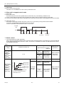
7. Heater control
1. Control specifications and DIP S/W setting
Table 1 shows how the field-installed heater is controlled. Select the desired pattern in the table below, and set the DIP S/W
on the outdoor and indoor units as shown in Table 1. See section 3 "Installation" for details. The table below shows Heater
Control patterns #A and B.
Table.1
Outdoor unit
setting
Duct unit PE/PD/PF-NR(NL)
Î
(PEFY-P06,08,12,15,18,24
NMSU-E)
Condition of outdoor unit
DIP S/W3-4
OFF
(Indoor unit)
DIP S/W OFF
In the case of:
<TGMU>
S/W5-2 OFF
<THMU>
S/W5-10 OFF
<PUMY>
S/W4-4 OFF
N/A
DIP S/W3-4
ON
(Indoor unit)
DIP S/W ON
In the case of:
<TGMU>
S/W5-2 ON
<THMU>
S/W5-10 ON
<PUMY>
S/W4-4 ON
HWE08010
Condition of O/U
Normal drive
Normal drive
NON duct unit
(PL/PK/PC)
Heater control #A
(defrost/error:
Heater OFF)
Heater control #A
(defrost/error:
Heater control #A
Heater ON)
(defrost/error:
Heater ON)
Heater OFF
Heater OFF
DIP S/W3-4
OFF
(Indoor unit)
Heater control #A
(defrost/error:
Heater OFF)
DIP S/W3-4
ON
(Indoor unit)
Heater control #B
(defrost/error:
Heater control #B
Heater ON)
(defrost/error:
Heater ON)
Defrost drive
H/P drive
H/P stop
a
b
c
d Outdoor temp.
Defrost drive
H/P drive
H/P stop
㪧㪸㫉㪸㫄㪼㫋㪼㫉㫊㩷a/b/c/d are set by㩷
maintenance tool.
- 15 -
GB
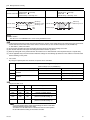
[ VII Microprocessor Control ]
Table.2
Heater OFF
Inlet air temp.
set temp.
Heater control #A
Heater ON
Inlet air temp. < set temp.-4°F
Heater control #B
Set temp.
Set temp.-1.8°F
Set temp.-4°F
Inlet air temp.
ON
OFF
Heater output
Heater OFF
Inlet air temp. set temp.
Heater ON
Inlet air temp. < set temp.-1.8°F
Set temp.
Set temp.-1.8°F
Inlet air temp.
ON
OFF
Heater output
<For heater>
The value "4°F" is modifiable from 1.8°F to 9°F by maintenance tool.
(1) On the ducted model units (except the Fresh air intake type), turning on the heater with the fan setting set to OFF requires that
the DIP S/W and connectors on the indoor units*1 are set on site. (in case of PEFY-P06,08,12,15,18,24NMSU-E)
*1: DIP SW 3-4, CN24, and CN4Y
(2) On the Fresh air intake type units, the heater cannot be turned on with the fan setting set to OFF.
(3) Non-ducted models do not require the settings described in Section (1) above.
(4) Back-up heating will not be performed when the heater turns on while demand control is performed (not a request item).
(5) This is applicable only to the R410 series. Make the settings for the following dip switches on the outdoor unit control board
before switching on the power.
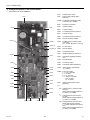
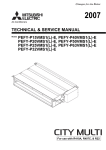
2. Fan control
By using the optional parts PAC-YU25HT, fan speed can be controlled.
Pattern
Duct unit PE/PD/PF-NR(NL)
Î
(PEFY-P06,08,12,15,18,24NMSU-E)
CN4Y for FAN control (YU25)
1
DIP S/W3-4 (Indoor unit)
Fan in defrost
OFF
Stop (Heater OFF)
ON
L / LL / Set * (Heater ON)
OFF
Stop (Heater OFF)
ON
Stop (Heater ON)
Disabled
2
3
Enabled
4
*depend on SW1-7/1-8
SW3-1
SW1-7
SW1-8
Fan speed *1
OFF
OFF
OFF
Very low
OFF
ON
OFF
Low
OFF
OFF
ON
Remote controller setting
OFF
ON
ON
Stop
(Remote controller setting *2)
ON
ON
ON
Stop
(Remote controller setting *2)
*1 The fan operates at the same speed settings as shown in this table
during the Heating Thermo-OFF mode.
*2 If Pattern 2 in the table above is selected for the fan control pattern,
the fan will follow the setting of the remote controller.
HWE08010
- 16 -
GB
[ VII Microprocessor Control ]
Reference (not applicable to the ducted models)
Pattern
1
NON duct unit (PL/PK/PC)
CN4Y for FAN control (YU25) *3
DIP S/W (Indoor unit)
Fan in defrost
N/A
N/A
Stop (Heater ON)
*3 Refer to Section 5 "Dipswitch Setting" for further information about each switch.
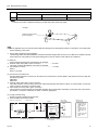
<Image>
CN4Y for FAN control
(PAC-YU25HT)
This is applicable only to the R410A series. Make the settings for the following dip switches on the indoor unit control board
before switching on the power.
3. PAC-YU25HT (Optional Parts) installation
The following section describes installation of the External Heater Adapter that connects to CITY MULTI air conditioner R410A
series indoor unit. This products is the special wiring parts to drive an electric heater with the air conditioner.
(1) Parts list
Check that the following parts are included in the package.
1) External output cable (with a yellow connector).............................2 in total
Two types of cables with different connectors are included.
2) Panel heater connector.................................................................. 3 in total
White: 1
Green: 2 (2 types)
(2) Connection to the indoor unit
Use the cables that fit the connectors on the indoor unit control board. The items listed in this parts list cannot be used with
the following models.
PMFY-BM
PMFY-AM
1) External output cable (with a yellow connector)
This cable is used to connect a relay circuit for an interlocked operation with either an electric or a panel heater. Connect the
cable to CN24 on the indoor unit control board.
2) Panel heater connector (with a green connector)
This connector is used to perform an interlocked operation with a panel heater. Depending on the indoor unit control board
specification, connect the cable either to CN4Y or CN22 as appropriate.
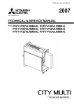
(3) Locally procured wiring
A basic connection method is shown below.
1) PEFY-P-NMSU-E and other models
Electric Heater
power source
Remote control board
Relay circuit
1
White
2
White
1
X
X
Preparations in the field
3
(applicable only when a panel
heater is connected)
CN22
CN4Y
W h it e
Red
Yellow
CN24
Electric Heater
or panel
heater
HWE08010
Indoor unit
control board
Adapter
Dip switch SW3-2 “ON”
Outdoor unit
control board
• PUHY, PURY-PTGMU type Dip
switch SW5-2
“ON”
• PUHY, PURY-PYHMU type Dip
switch SW5-10
“ON”
• PUMY series Dip
switch SW4-4
“ON”
Maximum cable length
is 10 m (32ft)
- 17 -
GB
[ VII Microprocessor Control ]
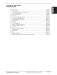
2) PEFY-P-NMHU-E, PDFY-P-NMU-E and other models
Electric Heater
power source
Remote control board
Relay circuit
Indoor unit
control board
Adapter
White
2
White
1
X
X
Electric Heater
or panel
heater
2
(applicable only when a panel
heater is connected)
CN22
Green
1
Yellow
CN24
Red
Dip switch SW3-2 “ON”
Outdoor unit
control board
• PUHY, PURY-PTGMU type Dip
switch SW5-2
“ON”
• PUHY, PURY-PYHMU type Dip
switch SW5-10
“ON”
• PUMY series Dip
switch SW4-4
“ON”
Maximum cable length
is 10 m (32ft)
Preparations in the field
For relay X use the specifications given below Operation coil
Rated voltage: 12VDC
Power consumption: 0.9W or less
* Use the diode that is recommended by the relay manufacturer at both ends of the relay coil.
The length of the electrical wiring for the PAC-YU25HT is 2 meters (6-1/2 ft.)
To extend this length, use sheathed 2-core cable.
Control cable type: CVV, CVS, CPEV or equivalent.
Cable size: 0.5 mm2 ~ 1.25 mm2 (16 to 22 AWG)
Don't extend the cable more than 10 meters (32ft)
Recommended circuit
FS1
H1
88H
FS2
FS1
H2
88H
FS2
R
Wiring diagram
1-phase power
supply
S
208V, 230V/60Hz
R
S
FS1, 2 ----- Thermal fuse
26H
88H
Control board
H1, H2 ----- Heater
26H --------- Overheat protection
thermostat
88H --------- Electromagnetic contactor
CN24
(4) Wiring restrictions
Keep the length of the cable connecting to the circuit board of the indoor unit shorter than 10 meters (32ft).
Longer than 10 meters (32ft) could cause improper operation.
Use a transit relay when extending wiring such as remote wiring.
HWE08010
- 18 -
GB
[ VIII Troubleshooting ]
VIII Troubleshooting
[1] Troubleshooting
1. Check methods
1. Component and check points
(1) Thermistor
Room temperature thermistor (TH21)
Liquid pipe thermistor (TH22)
Gas pipe thermistor (TH23)
Disconnect the connector and measure the resistance between terminals with a tester.
(Ambient temperature 10°C - 30°C[50°F-86°F])
Normal
4.3k
Abnormal
- 9.6k
Open or short
(Refer to the thermistor characteristic graph below.)
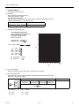
1) Thermistor characteristic graph
Low-temperature thermistor
Room temperature thermistor (TH21)
Liquid pipe thermistor (TH22)
Gas pipe thermistor (TH23)
Drain sensor (DS)
50
40
Thermistor R0 = 15 k
3%
Multiplier of B = 3480 k
2%
0°C 32°F
10°C 50°F
20°C 68°F
25°C 77°F
30°C 86°F
40°C 104°F
1
273+t
1 )}
273
30
(B)
Rt = 15 exp { 3480(
15k
9.6k
6.3k
5.2k
4.3k
3.0k
20
(A) Temperature
(°C)[°F]
(B) Resistance
(k )
10
0
-20
-4
-10
14
0
32
10
50
20
68
30
86
40 50
104 122
(A)
(2) Fan motor (CNMF)
Refer to the page on "DC fan motor (fan motor/indoor control board)."
(3) Linear expansion valve
Disconnect the connector, and measure the resistance between terminals with a tester.
Refer to the next page for details.
(F)
(E)
(D)
M
(C)
(B)
LEV
(A)
Normal
CN60
1
2
3
4
5
6
1-5
White-Red
200 k
(A)
Brown
(D)
Orange
(B)
Red
(E)
Yellow
(C)
Blue
(F)
White
HWE08010
2-6
Yellow-Brown
Abnormal
3-5
Orange-Red
4-6
Blue-Brown
Open or short
10%
- 19 -
GB
[ VIII Troubleshooting ]
1) Summary of linear expansion valve (LEV) operation
The LEV is operated by a stepping motor, which operates by receiving a pulse signal from the indoor control board.
The LEV position changes in response to the pulse signal.
Indoor control board and LEV connection
(G)
12VDC
(A)
6
(C)
(B)
5
(A)
(C)
4
(E)
(D)
3
(E)
2
(F)
1
(J)
4
M
6
5
2
1
(F) (B) (D)
3
(I)
(H)
(A)
Brown
(F)
White
(B)
Red
(G)
Control board
(C)
Blue
(H)
Connection (CN60)
(D)
Orange
(I)
Drive circuit
(E)
Yellow
(J)
Linear expansion valve
Pulse signal output and valve operation
Phase
number
1
2
Output pulse
ø1
ON
OFF
OFF
ON
ø2
ON
ON
OFF
OFF
ø3
OFF
ON
ON
OFF
ø4
OFF
OFF
ON
ON
3
4
The output pulse changes in the following order:
When the valve closes 1 -> 2 -> 3 -> 4 -> 1
When the valve opens 4 -> 3 -> 2 -> 1 -> 4
When the valve position remains the same, all output signals will be OFF.
If any output signal is missing or if the signal remains ON, the motor vibrates and makes clicking noise.
HWE08010
- 20 -
GB
[ VIII Troubleshooting ]
2) LEV operation
(f)
(a)
(a)
Close
(b)
Open
(c)
Fully open valve (2000 pulses)
(d)
No. of pulses
(e)
Extra tightning (80 - 100 pulse)
(f)
Valve opening degree
(b)
(c)
(d)
(e)
When the power is turned on, a pulse signal of 2200 pulses is output (valve closure signal), to bring the valve to position A.
When the valve is operating normally, it is free of vibration noise. If the valve locks or when it goes from point E to A in the
figure, it makes louder noise than would be heard when there is an open phase.
Check for abnormal sound/vibration by placing the metal tip of a screwdriver against the valve and the handle side against
your ear.
3) Troubleshooting
Symptom
Checking Criteria
Remedy
Circuit failure on
Disconnect the connectors on the control board, and connect LEDs to test the cirthe microcomputer cuit as shown below.
6
5
Replace the indoor control
board if driving
circuit failure is
detected.
4
3
2
1
1k
LED
Pulse signals are output for 10 seconds when the main power is turned on. If there
are LEDs that do not light up at all or remain lit after the pulses are turned off, there
is a problem with the driving circuit.
Locked LEV
The motor will idle and make small clicking noise if it is run while the LEV is locked.
If this clicking noise is heard both when the valve is fully closed and while it is being
opened, it indicates a problem.
Replace the LEV.
Disconnected or
shorted LEV motor
coils
easure the resistance between the coils with a tester (red-white, red-orange,
brown-yellow, brown-blue). The normal range of resistance is 150
10%
Replace the LEV.
HWE08010
- 21 -
GB
[ VIII Troubleshooting ]
Symptom
Checking Criteria
Remedy
Valve closure failure (leaky valve)
To check the LEV on the indoor unit, check the indoor unit liquid pipe temperature
that appears on the operation monitor on the outdoor unit's multi control board while
operating the indoor unit in question in the FAN mode and the other indoor units in
the cooling mode.
Replace the LEV
if the amount of
leakage is great.
(A)
Termistor (TH22)
(A)
LEV
Normally, the LEV is fully closed while the unit is in the FAN mode. If the valve is
leaky, liquid pipe thermistor reading will be lower than normal. If it is significantly
lower than the inlet temperature on the remote controller, valve closure failure is
suspected. If the amount of leakage is insignificant, replacement of LEV is unnecessary unless it is causing a problem.
Misconnections of Perform a visual check for disconnected connectors.
connectors or con- Perform a visual check of lead wire color.
tact failure
Disconnect the
connectors on
the control board
and perform a
continuity test.
(4) Drain-up mechanism
Measure the resistance between the terminals with a tester.
(coil temperature 20°C[68°F])
Normal
Abnormal
1
340
3
Open or short
(5) Drain float switch (CN4F)
Disconnect the connector, and measure the resistance between terminals with a tester.
(A)
1
2
3
4
(B)
(C)
(A)
Moving part
(B)
Switch
(C)
Magnet
(A)
HWE08010
Position of the moving part
Normal
Abnormal
Up
Short
(any position but short)
Down
Open
(any position but open)
- 22 -
GB
[ VIII Troubleshooting ]
2. DC fan motor (fan motor/indoor control board)
1. CAUTION
A high voltage is applied to the connector for connection to the fan motor (CNMF).
Do not unplug the connector CNMF with the unit energized to avoid damage to the indoor control board and fan motor.
2. Troubleshooting
Symptom: Indoor unit fan does not run.
Check fan motor connector contact
(CNMF).
Is the fan motor connector
(CNMF) fully inserted?
Yes
No
Fix the connection.
Power supply voltage
VDC
Check the power supply.
Measure the voltage at the indoor control board.
294 - 340VDC (same with the voltage between fan connector 1 (+) and 4(-))
Power supply voltage
VDC
208VAC
294VDC
220VAC
311VDC
230VAC
325VDC
240VAC
340VDC
15VDC (same with the voltage between fan connector 5 (+) and 4(-))
1 - 6.5VDC (same with the voltage between fan connector 6 (+) and 4(-))
[Values for Vsp are the values that are measured with the fan motor in operation.
Vsp is 0V when the fan motor is stopped.]
Is the voltage within the
normal range?
No
Replace the indoor control board.
Yes
Check the fan motor position thermistor signal.
Get the motor to make a full rotation or more, and measure the voltage at the test point
VFG.
(same with the voltage between fan connector 7 (+) and 4(-))
Are 0VDC and 15VDC
displayed alternately?
No
Replace the motor.
Yes
Replace the indoor control board.
HWE08010
- 23 -
GB
[ VIII Troubleshooting ]
3. Address switch setting
Make sure that power to the unit is turned off.
(A)
(B)
ON
OFF
ON
OFF
2
1
(A)
Indoor unit control board
(B)
Factory setting (all models)
1. When using an ME remote controller, set the address with the rotary switches (SW11, SW12).
Address setting is not required when the unit remote controller is used.
On-site address setting is required for the indoor units to run.
2. Address settings vary in different systems.
Refer to the section on address setting in the outdoor unit installation manual.
3. Address is set with a combination of SW12 (10's digit) and SW11 (1's digit).
To set the address to "3," set SW12 to "0" and SW11 to "3."
To set the address to "25," set SW 12 to "2" and SW 11 to "5."
HWE08010
- 24 -
GB
[ VIII Troubleshooting ]
4. Voltage test points on the control board
1. PEFY-P06,08,12,15,18,24NMSU-E
Fuse
CND
CNP
С25(*1)
CNMF
C951(*1)
PC941(*1)
CN2M
LED1
SWE
SW2
CN3C
CN20
SW4
CN24
CN42
CN4F
SW3
CN44
Fuse
Fuse(AC 250V 6.3A)
CND
Power supply voltage (208 230VAC)
CN2M
For M-NET transmission cable
connection (24 - 30VDC)
SWE
Emergency operation
SW2
Capacity setting
SW4
Function setting
CN42
For address board connection
SW3
Function setting
CN81
For address board connection
CN32
Remote start/stop adapter
CN3A
For MA remote controller cable
connection
(10 - 13 VDC (Between 1 and 3.))
CN4Y
For fan control
CN52
Remote display
CN51
Centralized control
CN41
JAMA standard HA terminal A
CN44
Thermistor (liquid/gas temperature)
CN4F
Float thermistor
CN24
For heater control
CN20
Thermistor (Inlet temperature)
CN3C
Indoor-outdoor transmission
(0 - 24VDC)
CNMF Fan motor output
1 - 4: 310 - 340 VDC
5 - 4: 15 VDC
6 - 4: 0 - 6.5 VDC
7 - 4: Stop 0 or 15 VDC
Run 7.5 VDC
(0 - 15 pulse)
CNP
CN81
CN41
Drain-up mechanism output
(200VAC)
(*1)
CN32
CN51
CN52
VFG Voltage on the (-) side of PC941
and C25
(Same with the voltage between 7
(+) and 4 (-) of CNMF)
VCC Voltage between the C25 pins
15 VDC
(Same with the voltage between 5
(+) and 4 (-) of CNMF)
LED2 CN3A
HWE08010
CN60 CN4Y
- 25 -
Vsp Voltage between the C951 pins
0VDC (with the fan stopped)
1 - 6.5VDC (with the fan in operation)
(Same with the voltage between 6
(+) and 4 (-) of CNMF)
GB
[ VIII Troubleshooting ]
5. Dipswitch setting (Factory setting)
1. Function setting
(1) SW1
Switch position
Function
Switch setting
ON
OFF
1
Active Thermistor (Intake air thermistor)
Built-in thermistor on the remote
controller
Indoor unit
2
Filter clogging detection
Available
Unavailable
3
Filter life
2500 hr
100 hr
4
Outdoor air intake
Enabled
Disabled
5
Remote display
Thermo-ON signal
Fan output
6
Humidifier operation
During heating mode
During heating operation
7
Fan speed
Low
Very low
8
Fan speed at heating Thermo-OFF Preset fan speed
Follows the setting of SW1-7
9
Auto restart after power failure
Enabled
Disabled
10
Power start/stop
Enabled
Disabled
1) Adress board
Factory setting
(2) SW3
Switch position
Function
Switch setting
ON
1
Unit type
Cooling only
OFF
Heat pump
2
-
-
-
3
-
-
-
4
Heater backup
Enabled
Disabled
5
-
-
-
6
-
-
-
7
-
-
-
8
Sensible temprature correction
9
Superheat setting tempurature*1
Disabled
-
Enabled
-
10
Sub cool setting tempurature*1
-
-
*1 Please don't use SW3-9,10 as trouble might be caused by the usage condition.
1) Indoor control board
Dipswitch settings must be made while the unit is stopped.
Factory setting
HWE08010
PEFY-P06NMSU-E
PEFY-P08NMSU-E
PEFY-P12NMSU-E
PEFY-P15NMSU-E
PEFY-P18NMSU-E
PEFY-P24NMSU-E
- 26 -
GB
[ VIII Troubleshooting ]
2. Capacity code setting
(1) SW2
1) Indoor control board
Dipswitch settings must be made while the unit is stopped.
Factory setting
The switches are set to correspond to the unit capacity.
PEFY-P06NMSU-E
PEFY-P08NMSU-E
PEFY-P12NMSU-E
PEFY-P15NMSU-E
PEFY-P18NMSU-E
PEFY-P24NMSU-E
3. Model setting
(1) SW4
1) Indoor control board
Dipswitch settings must be made while the unit is stopped.
Factory setting
Note:
Changes made to the dipswitches SW1, SW2, and SW3 will become effective when the unit comes to a stop (remote controller
off). There is no need to power cycle the unit.
4. External static pressure
(1) SWA, SWC
1) Address board
All models
5[0.02]
15[0.06]
2
2
3
3
2
2
1
1
1
1
SWA SWC SWA SWC
35[0.14]
2
3
2
1
1
SWA SWC
Pa[in.WG]
50[0.20]
Factory
setting
2
3
2
1
1
SWA SWC
3
2
1
SWA
(A)
(B)
2
1
SWC
(A) Option
(B) Standard
Note:
Changes that are made to the dipswitches SWA and SWC immediately become effective regardless of the unit's operation
status (RUN/STOP) or the remote controller status (ON/OFF).
5. 1's and 10's digits
(1) SW11, SW12 (Rotary switch)
The use of a network remote controller (PAR-F27MEA) requires address setting.
1) Address board
Address settings must be made while the unit is stopped.
Factory setting
HWE08010
- 27 -
GB
[ VIII Troubleshooting ]
6. Connection No. setting
(1) SW14 (Rotary switch)
This switch is used when the unit connected to an R2 series of outdoor unit.
1) Address board
Factory setting
Note:
Changes to the dipswitches SW11, SW12, SW14, and SW15 must be made while the unit is stopped and the remote controller
is OFF.
HWE08010
- 28 -
GB
[ IX Disassembly Procedure ]
IX Disassembly Procedure
[1] Disassembly Procedure
1. Control box
Exercise caution when removing heavy parts.
1. Removing the control box cover
(1) Remove the two fixing screws on the cover (A) to remove
it.
(A)
Fig.1
Fig.2
HWE08010
- 29 -
GB
[ IX Disassembly Procedure ]
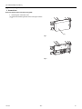
2. Thermistor (Intake air)
Exercise caution when removing heavy parts.
1. Remove the control box cover according to the procedure
in section [1].
2. Remove the thermistor.
(1) Remove the two fixing screws on the metal base (B) to remove it.
(B)
Fig.3
(2) Pull out the thermistor holder (C) and thermistor (D) on
the control box.
(C), (D)
Fig.4
HWE08010
- 30 -
GB
[ IX Disassembly Procedure ]
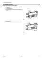
3. Drainpan
Exercise caution when removing heavy parts.
1. Removing the filter and the bottom plate
(1) Push down the tab on the filter, and pull out the filter in
the direction of the arrow 1.
(2) Remove the fixing screws on the bottom plate (D), (E) to
remove it.
(a)
(a)
(a)
(a)
(D)
(E)
Fig.5
2. Removing the drainpan
(1) Pull out the drain pan in the direction of the arrow 1.
Fig.6
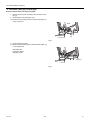
Note
Drain the water out of the drain pan before removing
it.
To avoid dew condensation, use insulated screws in
the places marked with circles in Figure 7.
(a)
(E)
Fig.7
(a)
HWE08010
- 31 -
Insulation material
GB
[ IX Disassembly Procedure ]
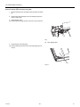
4. Thermistor (Gas pipe) (Liquid pipe)
Exercise caution when removing heavy parts.
1. Remove the drain pan according to the procedure in section [1].
2. Removing the Heat exchanger cover
(1) Remove the four fixing screws on the heat exchanger cover (F) to remove it.
HEX
(F)
Fig.8
3. Removing the thermistor
(1) Remove the thermistor (G) from the thermistor holder (H)
on the copper tube.
Thermistor size
Liquid pipe: ø8mm
Gas pipe: ø6mm
(G), (H)
Fig.9
HWE08010
- 32 -
GB
[ IX Disassembly Procedure ]
5. Fan and fan motor
Exercise caution when removing heavy parts.
1. Removing the filter and the bottom plate
(1) Push down the tab on the filter, and pull out the filter in the
direction of the arrow 1.
(2) Remove the fixing screws on the bottom plate (J) to remove it.
(a)
(a)
(a)
(a)
(J)
Fig.10
(a)
Tab
2. Removing the punching metal
(1) Remove the two fixing screws on the punching metal (K)
to remove it.
(a)
3. Removing the fan casing (bottom half)
(1) Squeeze the tabs on the fan casing to remove it in the direction of arrow 2.
(K)
Fig.11
4.
(1)
5.
(1)
Removing the motor cable
Remove the motor cable threw the rubber bush.
Removing the fan motor and the Sirocco fan
Remove the two motor fixing screws to remove the motor
and the Sirocco fan in the direction of arrow 3.
Fig.12
(2) Remove the four fan case fixing screws to take the top
half of the fan casing off.
Fig.13
HWE08010
- 33 -
GB
[ IX Disassembly Procedure ]
6. Bearing
P15, P18, P24 models only.
Exercise caution when removing heavy parts.
1. Removeing the bearing
(1) Remove the two fixing screws on the bearing cover (M)
to remove it.
(M)
Fig.14
(2) Remove the two bearing retainer screws to remove the
bearing.
Fig.15
HWE08010
- 34 -
GB
[ IX Disassembly Procedure ]
7. Heat exchanger
Exercise caution when removing heavy parts.
1. Remove the drain pan according to the procedure in section
[1].
2. Remove the heat exchanger cover according to the procedure in section [4] 2.
3. Removing the cover
(1) Remove the two fixing screws on the cover (T) to remove it.
(T)
Fig.16
(T)
Pipe support plate
4. Removing the Heat exchanger
(1) Remove the fixing screws on the heat exchanger (S) to remove it.
(S)
Fig.17
HWE08010
- 35 -
GB
Jul. 2008 HWE08010
Printed in Japan
New publication, effective Jul. 2008
Specifications subject to change without notice