1
Troubleshooting ECU Programmed by Bodybuilders
Tony Lindgren
Department of Computer and System Sciences
Stockholm University
Forum 100
164 40 Kista, Sweden
and
Scania CV AB
Service Support Solutions, YSNS
Verkstadsv¨agen 17, By 280
151 87 S¨odert¨alje, Sweden
Abstract—Having an Electronic Control Unit (ECU) which
is programmable by external parties puts new requirements on
troubleshooting. In this paper we describe how one could solve
the problems of both troubleshooting additional equipment
added by bodybuilders and facilitating their need to use
signals from vehicles in an easy way in order to interact
with their additional equipment. In this paper we look at
bodybuilder’s additional equipment for heavy trucks, but our
technique for troubleshooting should be equally relevant for
other applications with similar conditions.
Keywords-Diagnostics, Simulation, Reconfigurable hardware,
Signal processing systems
I. I NTRODUCTION
In heavy truck industry, bodybuilders use the trucks as
platforms for their additional hardware. There exists a wide
variety of additional hardware ranging from concrete mixers
to cranes. Other industries face similar type of add-ons to the
base platform to suit the needs of the user. Applications that
adhere to this general description are ranging from military
jet planes to farming equipment. They have the same basic
demand, in that the user want to equip a base platform to suit
their needs and want this equipment to be configured to work
in conjunction with the base platform. Obviously interfaces
are needed so that the equipment and base platform can
work together; the interfaces needed differ from application
to application. In this paper we focus on the base platform
of heavy trucks and describe how we facilitate bodybuilder’s
equipment to work in conjunction with this platform.
Heavy trucks do not have a high demand for fast changes
upon the added equipment in contrast to for example military
planes which must be able to swiftly configure the platform
to the payload and to the mission at hand. But nevertheless
is should still be possible to change and/or adjust the
equipment to cope with new customer demands or totally
new demands from a new owner of the truck.
Usually this has been handled by providing the bodybuilders with a dedicated Electronic Control Unit (ECU)
which they could use to interact with the truck’s Controlled
Area Network (CAN) by pre-defined control- and information signals. We will in the reminder of the text use the term
DE for the dedicated ECU provided to bodybuilders.
The bodybuilder then could define logical expressions,
typically using relays, to control the usage of their equipment. By using relays and the DE the bodybuilder could
create functions with desired behavior.
A consequence of having the logic outside the DE and
(often) realized through electrical switches and relays, made
it difficult for workshops to troubleshoot the bodybuilder’s
equipment. If the workshop is lucky the truck operator
had some form of electrical schematics of the additional
equipment. But it is not always the case, and if more than
one bodybuilder has added their equipment to the truck it
could be the case that one bodybuilder alter another bodybuilders electrical wiring to fit their needs. Thus giving rise
to the problem of not having up-to-date electrical schematics
for additional equipment making the job at the workshop
challenging and time-consuming.
By expanding the capabilities of the DE used for interacting with the bodybuilder’s additional equipment it is possible
to improve upon the above mentioned problems. The term
EDE will hence forward be used for DEs with expanded
capabilities. This includes creating tools that support bodybuilders in realizing their logical functions that control their
equipment within the EDE, which eliminate the problems
of having not having up-to-date electrical schematics. But
the major benefit is that these onboard schematics can be
used by a computer program to support the bodybuilder
as well as the workshop in their work with the additional
equipment. This includes services for verifying/testing the
logical design by simulation as well as introducing a service
for troubleshooting the additional equipment.
The usage of model based diagnosis ([2, 7]) to troubleshoot technical systems is an active research area and
techniques from this field have been used in a wide range
of applications from electronic circuits to gas turbines ([5]).
The problem setting we are looking at in this paper is
easier than the typical problem formulation within this field.
Usually this involves a system description, which typically
is a description of components and their connections. This
system description together with observation are used when
inferring (usually through abduction or consistency) which
components that are faulty, i.e. selecting one hypothesis out
of all hypotheses that either explain or is consistent with the
observations.
The parts that constitute model based diagnosis (MBD)
problem formulation as described above are a system description (SD) and observations (OBS) upon the system
together with the components (COMPS) of the system. Below is the MBD formulation for consistency and abduction
diagnosis.
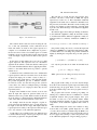
In figure 1 an example GUI of such a program is shown,
here the bodybuilder can define the logic of how their
additional equipment should work in conjunction with the
truck. To the left the GUI has two tree-structures showing
the current hardware, the EDE(s) connected, which the
bodybuilder are working with and the available CAN-signals
on the specific truck.
Consistencyf ormulation : SD ∪ COM P S ∪ OBS 6|= ⊥
Abductionf ormulation : SD ∪ COM P S |= OBS
In our setting we have the assumption that the internal
components of our model cannot be faulty. What can be
faulty is objects either “before” our logical expression - the
input, or “after” the logical expression - the outputs. This
simplifies our troubleshooting of the system, but also reduces
our ability to isolate faults to these points, i.e. to the input
or output.
The rest of the article is organized as such: in the next section we will give an example of how a bodybuilder can add
their logical functions to the EDE and how they can verify
their design. We will then look into how the workshop can
troubleshoot the logical functions that control the additional
equipment; here we will also go into some of the technical
details of how we realized this troubleshooting functionality.
In the section after we will look at the performance of
the simulation algorithm, and after that we will discuss our
experiences using this technique so far and finally we will
look at some related work.
II. C REATING FUNCTIONS
By using a computer program which can interact with the
EDE that we want to program, the bodybuilder can create
functions that control their additional equipment.
Such a program could use a graphical interface (GUI)
through which a bodybuilder can express their logical functions. Similar type of visual programming tools can be found
for other programming tasks see ([6]).
Functions can be formed using information signals from
the vehicle as well as control signals for requesting functions
from the vehicle. The physical EDE also has a few input pins
and output pins both digital and analog which can be used
in the functions. For bodybuilders with the need for many
pins or very complex expressions it could be possible to
connect a number of slave EDE(s) to the master EDE, thus
expanding the number of physical pins available.
Figure 1.
Here we see the main window of a bodybuilder application
In the figure only one (1) EDE is present, by navigating
in the structures it is possible to drag in pins of the EDE
and signals to the main canvas of the GUI. The same holds
true for the operators at the bottom of the figure. The user
then create logical expression by connecting the input, be it
CAN-information signals or pins, to operators and from the
operators to the output, which can be pins or CAN-control
signals.
The example application has two major modes, the on-line
mode and an off-line mode. When using the main window
in off-line mode the user needs to specify the hardware
configuration, i.e. the number of EDE(s). In addition to that
the production date / specification of a truck must be given
so that the correct list of available signals is used.
Programmable signals and pins can be used for input
and output and their colors define what type of signal they
indeed are. The input and output signals and their possible
connections are shown in table I.
Table I
H OW SIGNALS CAN BE COUPLED
Input
Digital Pin
Information signal
PWM
Output
Digital or PWM Control signal
1
1
1
1
1
0
In the table a 1 denotes that it is possible to connect the
two signal types. The current operators with the exception
of the branch operator (the rightmost symbol) are only valid
for digital Pins, Information- and Control-signal types. They
symbols represent the usual interpretation of NOT, OR, AND
and BRANCH operators.
III. T ROUBLESHOOTING
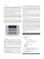
Figure 2.
The simulation view
The software checks each user action involving the canvas, so that only syntactically correct connections can be
made and checks are made if the logical expression is
complete or not. Feedback about completeness is given to
the user in form of circles colored either green or red. The
feedback is given on both the whole logical expression and
on the used input / output connections and for each operator
used.
In the canvas of main window above we can see a small
logical expression. The expression uses two information
signals from the vehicle to make sure that the vehicle speed
is less than 5 km/h and that the driver is applying the brakes,
if this is so the vehicle kneels and it is possible to open the
vehicles doors.
A simulation view is available for the user to validate their
logical expression. The user can in this view set the values
of input- and output ports to either: 1 (true), 0 (false) or ?.
Where the question mark denotes a free unbound variable,
the possible assignments give rise to different scenarios.
It could also be the case that the user put the system in
a state that is not valid (for example having a branching
operator connected to two output ports where they are true
respectively false).
In figure 2 the simulation view is shown, as can be seen
when all input and output are question marks, four (4)
different scenarios are possible. Each accessible via the tabs
above the canvas, a connection having a thick line illustrates
a true value while a thin line illustrates a false value.
For example when the user has designed a logical expression and uses the simulation view to test the expression,
he might see that the tabs are empty. This implies that the
logical expression is faulty, as the expression will never give
rise to any activation of the additional equipment.
A truth table is also available for the user. When the user
is satisfied with the design of their logical expression, they
can load the program into the physical EDE.
The task that we ponder here has the following characteristics: We have a truck with an EDE and logical
expression(s) loaded on to it. The bodybuilders additional
equipment on the truck does not function as intended, but it
has previously worked fine. The truck is in the workshop and
we have our computer program connected to it and the truck
is put in a state where the usage of the additional equipment
should work.
We can then support the workshop in finding out whether:
A, the additional equipment is faulty. B, the truck is faulty.
C, both the truck and the additional equipment is faulty. As
mentioned before a consistency formulation of MBD is as
follows:
Consistencyf ormulation : SD ∪ COM P S ∪ OBS 6|= ⊥
Our problem setting only need to consider the input and
output ports (PORTS) for potential abnormal behavior (AB),
i.e. faults. Hence we can change the problem formulation
slightly by dividing the components into ports and operators
(OP).
{c ∈ COM P S : c ∈ P ORT S ⊕ c ∈ OP }
It is only the ports that can be either in abnormal mode
or not.
{p ∈ P orts : AB(p) ⊕ ¬AB(p)}
While operators in our setting are always error free.
{o ∈ OP : ¬AB(o)}
The program in this setting, do not have any knowledge
about the world outside the logical expression. When doing
troubleshooting, the program hands over the conclusions
from the troubleshooting at the end of programs world (i.e.
the ports).
The program will assist the workshop in pointing out
which (ports) conditions that are not fulfilled for a certain
bodybuilder function. The program displays these ports
and hand over the rest to the workshop. Hence further
investigation might be needed to be able to point out which
component/s on the additional equipment and/or truck is
faulty.
The standard diagnostic services, the formation of diagnostic trouble codes (DTC), guided diagnostics etc. could
of course still be used for troubleshooting the EDE as for
other ECUs on a specific truck. Our concern in this paper is
how we support the workshop to answer the question “why
is the additional equipment no longer working properly?”.
A. Architecture
The troubleshooting has been implemented as a separate
module. We will briefly go through the different information
layers and their responsibilities and motivate why the module looks the way it does. The module is set up as a server
towards which another program can use the services exposed
by the module. The module offers two main services: a
simulation service and a troubleshooting service, where the
latter is an extension of the former.
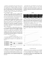
The module deals with information in three (3) different
formats, as shown in figure 3; Firstly the format in which it
communicates with outside world (XML schema); Secondly
the internal format and thirdly the format of the satisfiability
solver (SAT) used, for more information about SAT solvers
see ([4]).
The reason of having this (potentially not necessary)
internal format comes from the fact that when constructing
the software, we wanted to be able to use different SAT
solvers. Hence to avoid getting stuck on one particular SAT
solver, we decided to use an internal format.
and transform it into a SAT solver format. Create a wished
state for a particular bodybuilder functionality, the wished
state is usually found by setting the function’s activation to
1-true and the rest of the involved ports values to ?-unbound
value. Use this with the SAT solver to calculate all possible
scenarios when this function can be realized, i.e. a set of
sets where each set contains exactly one truth assignment to
all the involved ports.
The SAT solver is hence used for the given logical
expression and the values on the ports (observation) in
form of 1-true, 0-false or ?-unbound value, to calculate all
possible values for the wished situation. The output is a set
of sets, where each set is unique and consistent given the
wished situation.
For each set, in the set of sets (from the wished state),
we calculate the difference or inconsistencies between the set
and the current state. We then label each set with the number
of inconsistencies. When this labeling is done, we sort the
set of sets in ascending order with regard to inconsistencies.
We can then present this information to the user in this order.
One can regard an inconsistent value as one or more possible
faulty component(s). Using the common assumption that
fewer faulty components (or a simple hypothesis) are more
likely and as a consequence they are more likely to explain
the real fault. Which make sense if we regard that the
nature of faults in our components are rare, hence it is more
probable that few components fail at the same time.
In algorithm 1 a more formal specification of the algorithm is given.
Algorithm 1 The troubleshooting algorithm
Figure 3.
Information layers of the module
B. Algorithm
The algorithm is dependent on three (3) sources of information: the logical expression, a wished state and a current
state. The logical expression is sent to the system in a
XML format. The wished state is defined as the state when
a function is realized, i.e. when the output of the logical
expression for a particular function is interpreted to true.
The current state is the state that we observe upon the truck
right now.
Hence when a workshop wants to troubleshoot a bodybuilder’s equipment, the proposed diagnosis software is
activated for the EDE. The truck is set for activation of
the bodybuilder’s equipment. The software now calculates
the most probable reason of why the equipment is not
functioning as intended.
The algorithm for the troubleshooting informally works as
follows: Given the current EDE, get the logical expression
Inputs: logExpression, wishedState, currentState
Outputs: SortedLabeledSets
function SAT(Le, W s)
repeat
for all ws ∈ W s do
if ws = ? then
ws0 ← ASS C ON VAL(Le, ws, W s)
W s ← UP C ONS S ET(ws0 )
end if
end for
until No more unique sets
return W s0
end function
Le ← PARSE T O I NTERNAL F ORMAT(logExpression)
W s ← PARSE T O I NTERNAL F ORMAT(wishedState)
Cs ← PARSE T O I NTERNAL F ORMAT(currentState)
Sets ← SAT(Le, W s)
LabeledSets ← L ABLE S ET(Sets, Cs)
return S ORT(LabeledSets)
The inputs to the algorithm are the logical expression, the
wished state and the current state. Output is a sorted list of
sets containing ports for further investigation. The function
assConVal assigns values to the variable of the wished state
that are consistent with the posted constraints. The function
upConsSet updates the wished state, i.e. the variables in the
constraint store. The rest of the functions in the algorithm
have self-explanatory names.
First all three (3) input are parsed to internal format.
The SAT solver then finds all possible assignments (set of
sets) given the wished state and the logical expression. For
each set the labeling function marks which ports that is
inconsistent with the current set. The assignments are then
(set of sets) sorted with regard to marked ports.
The feedback the user receives is information on where
the fault lies. If the algorithm returns an empty set of sets
then the additional equipment needs further investigation.
Otherwise the truck and / or the additional equipment need
further investigation. The first set is presented to the user,
which since it is ordered, has a minimum of inconsistent
(ports/faulty components) in it. Here an inconsistent item(s)
is presented to the mechanic, it can be physical pins on the
EDE or CAN signals.
If it is a CAN signal, for example that the signal parkingbrake-applied is not present, this can be further investigated
by the mechanic. The cause could for example be a faulty
sensor. If it is a physical pin on the EDE the mechanic
can follow the attached wire and investigate the connected
equipment. If the mechanic cannot solve the problem using
the information presented, after checking each lead, the next
set is presented to the mechanic. This process continues until
the faulty component(s) are isolated.
In table II the result of the simulation is shown. The first
column denote the number of layers, the second column
the number of input, the third the number of operators, the
fourth the amount of time used by the CPU (in milliseconds)
and the last column shows the amount of memory used (in
kilobytes).
Table II
R ESULTS
No. layers
1
2
3
No. inputs
4
16
64
No. operators
3
15
63
CPU time
0
266
3751
Memory
2170,848
8721,824
123643,440
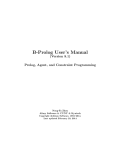
Figure 5 shows how CPU time and Memory usage (yaxis) correlate with the logical expressions complexity. The
CPU time is shown in milliseconds and the memory used in
kilobytes. In this case we use a crude measure of complexity
expressed by number of inputs * number of operators. This
gives the first layer complexity of 12 = 4 * 3.
In this figure we can observe that the number of input reuse affect the memory needs of the algorithm significantly.
Notice the sharp turn for the memory needs around 8700
kilobytes. The reason for this is that the re-used input does
not create more variables in the constraint store of the SATsolver.
IV. P ERFORMANCE
To test the performance of the algorithm, we set up
an experiment where we used a block consisting of two
(2) AND operators connected to one (1) OR operator (see
figure 4).
Figure 5.
usage
Figure 4.
The relation between complexity and CPU time and memory
One block
These blocks are then connected to each other in layers,
e.g. where one (1) output block that has four (4) input blocks
is considered as two (2) layers, to form bigger and bigger
logical expressions. When testing the performance, we ran
out of unique inputs when using the above logical expression
with three (3) layers as the prototype EDE could not handle
more input. We had to re-use a majority of the input for the
third layer.
V. R ELATED WORK
Mercedes have an ECU bodybuilder node called PSM
which stands for Parameterable Special Module. It is similar
to our proposed EDE in that a bodybuilder can define
logical expressions using a visual programming tool. But
to the authors knowledge they are lacking simulation and
troubleshooting capabilities.
Iveco and DAF has on some trucks the possibility of
bodybuilders to use CANOpen layer ([1]) for communication with their equipment. But no information was found
whether they have any troubleshooting assistance.
Volvo, Scania and other manufacturers use a dedicated
ECU that have certain signals that are available and the
output on the ECU connectors are defined by adjusting
parameters.
VI. D ISCUSSION AND CONCLUSION
As we showed in the performance section, even though
we are using a modern SAT solver which uses techniques
from [3], memory needs grows exponential with complexity
although this is disturbing, it has not been a practical
limitation. The reason for this is that the users tend not
to create very large expressions; instead the number of
expressions can be large for some vehicles. This does not
affect the complexity of simulation or troubleshooting.
As noted in the section related work the way of creating
logical expressions with a visual programming tool is not
new for the truck industry but using these logical expressions
to facilitating simulation and troubleshooting capabilities
probably is, which is the main contribution of this work.
The response from test users have been positive when
using the prototype software. They do see the benefit from
using this tool, as it will speed-up their process of adding
their equipment to the truck, as well as reducing the effort
of designing the logical expressions and verifying them. The
benefits to a workshop are swifter and easier troubleshooting
of not only the truck itself but also the bodybuilder’s
equipment.
A further improvement of the troubleshooting would be to
use fault frequency statistics over components when ordering
the sets. The ordering could then be improved, by presenting sets containing components with higher probability of
faults before components with lower probability. This could
hopefully speed up the fault isolation process even more.
Yet another possible improvement would be to create
dynamic troubleshooting guides that make use of the result
from our troubleshooting and the set of Diagnostic Trouble
Codes (DTCs) that are present on a particular truck.
R EFERENCES
[1]
C. E. 50325-4, CSN EN 50325-4 - Industrial communications subsystem based on ISO 11898 (CAN) for
controller-device interfaces - Part 4: CANopen. ISO,
Geneva, Switzerland.
[2] J. Biteus, E. Frisk, and M. Nyberg, “Condensed representation of global diagnoses with minimal cardinality
in local diagnoses,” in 17th International Workshop on
Principles of Diagnosis (DX-06), Spain, 2006.
[3]
R. E. Bryant, “Graph-based algorithms for boolean
function manipulation,” IEEE Trans. Comput., vol. 35,
no. 8, pp. 677–691, Aug. 1986, ISSN: 0018-9340. DOI:
10.1109/TC.1986.1676819. [Online]. Available: http:
//dx.doi.org/10.1109/TC.1986.1676819.
[4] K. Claessen, N. E´en, M. Sheeran, N. S¨orensson, A.
˚
Voronov, and K. Akesson,
“Sat-solving in practice,
with a tutorial example from supervisory control,” Discrete Event Dynamic Systems, vol. 19, no. 4, pp. 495–
524, 2009.
[5] L. Console and O. Dressier, “Model-based diagnosis in the real world: lessons learned and challenges
remaining,” in Proceedings of the 16th international
joint conference on Artificial intelligence - Volume 2,
ser. IJCAI’99, Stockholm, Sweden: Morgan Kaufmann
Publishers Inc., 1999, pp. 1393–1400. [Online]. Available: http : / / dl . acm . org / citation . cfm ? id = 1624312 .
1624416.
[6] LabVIEW. (2012). Labview system design software,
[Online]. Available: http://www.ni.com/labview/.
[7] R. Reiter, “A theory of diagnosis from first principles,”
Artificial Intelligence, vol. 32, no. 1, pp. 57–95, Apr.
1987.