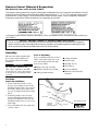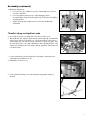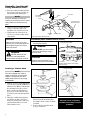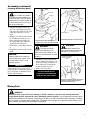
1
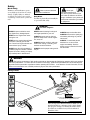
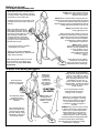
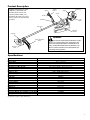
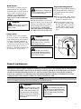
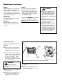
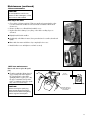
SHINDAIWA OWNER’S/OPERATOR’S MANUAL
C282 BRUSHCUTTER
WARNING!
X7502825302
02/13
Minimize the risk of injury to yourself and others! Read this
manual and familiarize yourself with the contents. Always wear
eye and hearing protection when operating this unit.
Introduction
The Shindaiwa 282 series is designed
and built to deliver superior
performance and reliability without
compromise to quality, comfort, safety
or durability.
Shindaiwa engines represent the
leading edge of high-performance
engine technology, delivering
exceptionally high power with
remarkably low displacement and
weight. As an owner/operator, you’ll
soon discover for yourself why
Shindaiwa is simply in a class by itself!
Contents
IMPORTANT!
The information contained in these
instructions describes units available at
the time of publication.
Echo, Inc. reserves the right to make
changes to products without prior
notice, and without obligation to
make alterations to units previously
manufactured.
The engine exhaust from
this product contains chemicals
known to the State of California
to cause cancer, birth defects or
other reproductive harm.
PAGE
PAGE
Safety......................................................3
Product Description..............................5
Specifications.........................................5
Emission Control..................................6
Assembly................................................6
WARNING!
Mixing fuel...........................................10
Filling the fuel tank.............................12
Starting the Engine ............................13
Stopping the Engine...........................13
Checking Unit Condition...................13
PAGE
Operating.............................................13
Maintenance........................................15
Long Term Storage.............................21
Troubleshooting Guide......................22
Warranty Statement............................25
Attention Statements
Throughout this manual are special “attention statements”.
DANGER!
A statement preceded by
the triangular attention symbol and
the word “DANGER” contains information that should be acted upon to
prevent serious injury or death.
WARNING!
A statement preceded by
the triangular attention symbol and
the word “WARNING” contains information that should be acted upon to
prevent serious bodily injury.
IMPORTANT!
A statement preceded by the word
“IMPORTANT” is one that possesses
special significance.
CAUTION!
A statement preceded by the
word “CAUTION” contains information that should be acted upon
to prevent mechanical damage.
NOTE:
A statement preceded by the word
“NOTE” contains information that is
handy to know and may make your job
easier.
IMPORTANT!
The operational procedures described in this manual are intended to help you get the most from this unit as well as to protect
you and others from harm. These procedures are guidelines for safe operation under most conditions, and are not intended to
replace any safety rules and/or laws that may be in force in your area. If you have questions regarding your unit, or if you do
not understand something in this manual, contact your local authorized Shindaiwa dealer. You may also contact Shindaiwa at
the address printed on the back of this Manual.
Warning and Operational Labels
Read and follow this operator's
manual. Failure to do so could
result in serious injury..
Wear eye and hearing protection
at all times during operation of
this unit. Wear head protection
where there is a risk of falling
objects.
50 FEET
(15m)
2
Make sure no one is
within 15 M / 50 feet of an
operating machine.
Beware of thrown or
richocheted objects
DO NOT operate this unit
with a blade unless the unit is
equipped with a Shindawiaapproved handlebar or barrier.
Always wear a harness when
operating this unit with a blade.
A harness is also recommended
when using trimmer line.
If unit is used as a brushcutter,
beware of blade thrust. A
jammed blade can cause the
unit to jerk suddenly and may
cause the operator to lose control of the unit.
WARNING ! Surface can
be hot. Always wear gloves
when handling this unit.
Safety
Work Safely
Trimmers and brushcutters operate
at very high speeds and can do serious
damage or injury if they are misused
or abused. Never allow a person without training or instruction to operate this
unit!
WARNING!
WARNING!
Never make unauthorized
attachment installations.
Never operate power equipment of
any kind if you are tired or if you
are under the influence of alcohol,
drugs, medication or any other substance that could affect your ability
or judgement.
Stay Alert
You must be physically and mentally fit
to operate this unit safely.
WARNING!
Use Good Judgment
ALWAYS inspect unit before each
use. Replace any damaged parts.
NEVER extend trimming line beyond
the length specified for your unit.
NEVER run the engine when transporting the unit.
ALWAYS keep the unit as clean as
practical. Keep it free of loose vegetation, mud, etc.
NEVER run the engine indoors! Make
sure there is always good ventilation. Fumes from engine exhaust can
cause serious injury or death.
ALWAYS stop the unit immediately if
it suddenly begins to vibrate or shake.
Inspect for broken, missing or improperly installed parts or attachments.
ALWAYS keep the handles clean.
ALWAYS disconnect the spark plug
wire before performing any maintenance work.
ALWAYS hold the unit firmly with both
hands when cutting or trimming, and
maintain control at all times.
ALWAYS use the proper cutting tool for
the job.
ALWAYS, if a saw blade should
bind fast in a cut, shut off the
engine immediately. Push the
branch or tree to ease the bind and
free the blade.
WARNING!
The ignition components of this machine generate an electromagnetic field during operation which may interfere
with some pacemakers. To reduce the risk of serious or fatal injury, persons with pacemakers should consult with their
physician and the pacemaker manufacturer before operating this machine. In the absence of such information, ECHO
does not recommend the use of ECHO products by anyone who has a pacemaker.
Safety Labels
This label indicates the minimum distance between
front handle and rear grip per ANSI B175.3.
IMPORTANT!
Safety and Operation Information Labels: Make sure all
information labels are undamaged and readable. Immediately replace damaged or missing information labels.
New labels are available from your local authorized
Shindaiwa dealer.
3
Safety (continued)
The Properly Equipped Operator
Wear hearing protection devices and a
broad-brimmed hat or helmet. A helmet
is required when using a blade-equipped
brushcutter to clear small trees.
Always wear eye protection such as
goggles or safety glasses to shield
against thrown objects.
Always wear a harness when operating the unit .
It adds comfort and helps ensure safety by limiting
movement fore and aft. When the harness is
adjusted properly, the unit should balance with the
cutting attachment parallel to the ground.
Prolonged exposure to excessive noise
is fatiguing and could lead to impaired
hearing.
Always operate with both hands
firmly gripping the unit.
Wear close-fitting clothing to
protect legs and arms. Gloves
offer added protection and are
strongly recommended. Do not
wear clothing or jewelry that
could get caught in machinery
or underbrush. Secure long hair
so that it is above shoulder level.
NEVER wear shorts!
When operating with a blade, make sure
the handle is positioned to provide you with
maximum protection from contacting the
blade. Always make sure the handlebar
is installed in accordance with the
manufacturers instructions.
Keep a proper footing and do not
overreach. Maintain your balance at all
times during operation.
Always make sure the
appropriate cutting attachment
shield is correctly installed and
in good condition. Do not
operate the unit if the
cutting attachment shield
is missing, loose, or
broken.
Wear appropriate footwear (non-skid
boots or shoes): do not wear opentoed shoes or sandals. Never work
barefooted!
Keep away from the rotating
trimmer line or blade at all
times, and never lift a moving
attachment above waist-high.
Long-term exposure to vibration
can damage your hands.
Be Aware of the Working Environment
Avoid long-term
operation in very hot
or very cold weather.
Make sure
bystanders
or observers
outside the
15 meter (50
feet) “danger
zone” wear eye
protection.
15 METERS
(50 FEET)
Be extremely careful
of slippery terrain,
especially during rainy
weather.
Be constantly alert for
objects and debris that
could be thrown either
from the rotating cutting
attachment or bounced
from a hard surface.
Always make sure
the appropriate
cutting attachment
shield is correctly
installed.
Reduce the risk of bystanders
being struck by flying debris. Make
sure no one is within 15 meters
(50 feet)— that’s about 16 paces
of an operating attachment. Stop
immediately if a child, pet, or
person comes within a 15 meter
(50 feet)radius. Outside this radius,
there is still a risk of injury from
thrown objects.
Do not operate the unit if the
cutting attachment shield is
missing, loose, or broken.
Beware of a coasting blade when
brushcutting or edging. A coasting
blade can injure while it continues
to spin after the throttle trigger
is released or after the engine is
stopped.
ALWAYS clear your work area of trash
or hidden debris that could be thrown
back at you or toward a bystander.
When operating in rocky terrain or
near electric wires or fences, use
extreme caution to avoid contacting
such items with the cutting attachment.
If contact is made with a hard object,
stop the engine and inspect the cutting
attachment for damage.
4
Product Description
Using the illustration as a guide,
familiarize yourself with your
machine and its various components. Understanding your
machine helps ensure top performance, long service life and safer
operation.
Ignition
Throttle
Throttle
interlock
Spark plug
Muffler
Hanger
Handlebar
Fuel
Tank
Outer Tube
Strap with
Protector
Gearcase
WARNING!
Cutting Attachment
Shield
Brushcutter
blade
Do not make unauthorized modifications or alterations to any of these units or their components. Shindaiwa must authorize alterations and modifications in
writing. Unauthorized modifications or alterations may
alter the machine operation and could jeopardize personal safety during operation.
Specifications
Model Name
Engine Type
Displacement
Bore and Stroke
Dr y Weight (less attachment)
Dimensions (L x H x W) mm
Fuel Tank Capacity
Fuel/Oil Ratio
Carburetor Type
Air Cleaner Type
Ignition
Spark Plug
Electrode Gap
Torque
Stopping Method
Starting Method
Transmission Type
Handle Type
Engine Idle Speed
Clutch Engagement Speed
Wide Open Throttle Speed (W.O.T.) w/ line head
Wide Open Throttle Speed (W.O.T.) w/ blade
C282
Air cooled, two stroke, single cylinder gasoline engine
28.9 cc / 1.8 cu. in.
30 x 35 mm / 1.2 x 1.4 in
7.0 kg / 15.5 lb.
1783 x 345 x 314 mm / 70.2 x 13.6 x 12.4 in.
750 mL / 25.4 oz.
50:1 with *ISO-L-EGD or JASO FD class engine oil
Walbro, WYK, diaphragm-type
Dual layer filter element
One-piece electronic, transistor-controlled
BPMR6A
0.6 mm/ .024 in.
16.7 - 18.6 N∙m / 148-165 in • lbf
Slide Switch
Recoil Starter
Automatic, centrifugal clutch w/bevel gear
Bicycle type
2,750 RPM
3,800 RPM
9,500 RPM
11,500 RPM
Specifications are subject to change without notice.
5
Emission Control (Exhaust & Evaporative)
EPA 2010 and Later and/or C.A.R.B. TIER III
The emission control system for the engine is EM (engine modification) and, if the second to last character of the Engine Family on the Emission Control Information label (sample below) is “C”, “K”, or “T”, the emission control system
is EM and TWC (3-way catalyst). The fuel tank/fuel line emission control system is EVAP (evaporative emissions).
Evaporative emissions for California models are only applicable to fuel tanks.
An Emission Control Label is located on the engine. (This is an EXAMPLE ONLY, information on label varies by engine FAMILY).
PRODUCT EMISSION DURABILITY (EMISSION COMPLIANCE PERIOD)
The 50 or 300 hour emission compliance period is the time span selected by the manufacturer certifying the
engine emissions output meets applicable emissions regulations, provided that approved maintenance procedures are followed as listed in the Maintenance Section of this manual.
Assembly
This unit comes fully assembled with
the exception of the handlebar, cutting attachment shield and cutting
attachment.
IMPORTANT!
The terms “left”, “left-hand”, and
“LH”; “right”, “right-hand”, and “RH”;
“front” and “rear” refer to directions as
viewed by the operator during normal
operation.
Prior to Assembly
Before assembling, make sure you have
all the components required for a complete unit and inspect unit and components for any damage.
■■Engine/Outer tube assembly
■■Handlebar and Throttle assembly
■■Cutting attachment shield
■■Cutting attachment
■■Shoulder strap
■■Assembly Tool (s)
■■Safety Glasses
■■Operator’s Manual
■■Emission Control Warranty
Statement
Handlebar
Install the handlebar:
1. Use the 4 mm hex wrench to remove
the lower cap retaining screws from the
handlebar bracket. Remove the cap from
the bracket, and note the position of the
two spacers installed between the bracket
halves.
2. Position the handle on the outer tube
forward of Handle Positioning Label as
shown. Reassemble the lower cap to the
handlebar bracket in the reverse order of
disassembly.
3. Locate the handle in the best position for
operator comfort.
6
Handlebar
Bracket
Handlebar
Spacer
Outer Tube
Spacer
Lower Cap
Retaining
Screws (A)
Lower cap
Handle Positioning Label
Assembly (continued)
4. Handlebar Adjustments:
a. Loosen 2 lower cap retaining screws (A) to adjust handlebar location on outer drive shaft tube.
b. Loosen 4 handlebar clamp screws to adjust handgrip position. Access handlebar clamp screws through 4 holes (J) in bottom of handlebar mounting bracket.
c. Tighten all clamp and retaining screws securely after making final adjustments.
J
J
E
E
A
E
J
J
E
Throttle Linkage and Ignition Leads
1. Loosen the air cleaner cover knob and remove the air cleaner cover.
2. Thread throttle cable adjuster (A) into throttle cable bracket (B), and install wire
end into large carburetor swivel hole (C). Check throttle for freedom of movement and that wide open throttle/low idle extremes are adjusted properly. Turn
the cable adjuster in or out to make adjustments. After adjusting, hold the cable
adjuster (A), and tighten the cable adjuster nut (D) against the cable bracket (B)
to lock the setting.
E
B
A
D
C
3. Connect 2 ignition stop leads from throttle cable tubing to ignition leads on
engine (E) and grounding screw (F).
4. Reinstall the air cleaner cover.
F
5. Secure plastic flex tubing to outer driveshaft tube using plastic clamps (I)
provided.
I
I
7
Assembly (continued)
Cutting Attachment Shield
1. Insert the cutting attachment shield
between the outer tube and the cutting attachment mounting plate.
NOTE:
Socket-Head
Cap Screws
It may be necessary to loosen the
retaining nut and clamp screw to adjust
cutting attachment shield mounting
plate.
2. Fit the two spacers and the bracket
over the outer tube and loosely
install the four socket-head screws.
3. Tighten the four socket-head cap
screws to secure the cutting attachment shield.
Spacer
Cutting Attachment
Shield w/subshield
Spacer
Retaining
Nut
Mounting Plate
Cutting attachment shield assembly
CAUTION!
Sub-Shield (when trimmer head is in use)
Make sure the clamp screw and
retaining nut are securely tightened
before tightening the four sockethead cap screws.
1. Attach the shield extension to the cutting attachment shield.
WARNING!
NEVER operate the unit
without the cutting attachment
shield installed and tightly secured!
NEVER use this machine
without sub-shield when using a
trimmer head.
1. With the gearcase output shaft facing
up, rotate the gearshaft and Holder A
until the hole in Holder A aligns with
the matching hole in the gearcase
flange, and then lock the holder to
the gearcase by inserting the long
end of the hex wrench through both
holes.
2. Using the combination spark plug/
screwdriver wrench, remove the
shaft bolt, and bolt guard. (The bolt
guard and shaft bolt are not used
with a trimmer head).
Hook Receiver
CAUTION!
Make sure the sub-shield is completely hooked at the hook receiver.
Sub-shield
Hook
Attach the shield extension to the cutting
attachment shield
Hand-tighten Trimmer Head (counterclockwise to install)
NOTE:
This unit is shipped with Holder A,
Holder B, shaft bolt, and bolt guard
installed. The shaft bolt is a LEFTHAND thread. Remove it by turning
CLOCKWISE!
Cutting Attachment Shield
WARNING!
Installing a Trimmer Head
8
Outer Tube
Bracket
Shaft Bolt
Bolt Guard
Holder B
Gear Shaft
Holder A
Hex Wrench
3. Using the hex wrench to secure
Holder A, install and hand-tighten
the trimmer head (counter-clockwise
to install).
4. Remove the hex wrench from the
gearcase and holder.
This unit is now completely
assembled and ready to use as
a trimmer.
Assembly (continued)
Installing Brushcutter Blade
Shaft Bolt
WARNING!
Bolt Guard
Do not attach any blade to
a unit without proper installation of
all required parts. Failure to use the
proper parts can cause the blade to
fly off and seriously injure the operator and/or bystanders.
1. Turn the unit upside down so the
gear case output shaft is facing UP
and remove the shaft bolt, bolt guard
and holder B from the gear case
shaft.
2. Align the hole in blade holder A with
the matching hole in the gear case
flange and then temporarily lock
the output shaft by inserting a hex
wrench through both holes.
3. Fit the blade over the flange on holder
A.
4. Install blade holder B on the output
shaft.
CAUTION!
Install the blade so its printed surface is visible to the operator when
the brushcutter is in the normal
operating position.
IMPORTANT!
Discard blades that are bent, warped,
cracked, broken or damaged in any way.
Use a sharp blade. A dull blade is more
likely to snag and thrust.
Holder B
Blade
Gear Shaft
Holder A
Output
Shaft
Blade Holder B
Hex wrench
Temporarily lock the output shaft by
inserting a hex wrench through both holes
WARNING!
The blade must fit flat
against the holder flange. The
blade mounting hole must be centered over the raised boss on blade
Holder A.
5. Install the bolt guard and then the
blade retaining bolt. Using the combination spark plug wrench/screwdriver, tighten the bolt firmly in a
counter-clockwise direction.
6. Remove the hex wrench.
Install blade holder B on the output shaft.
WARNING!
Holder B must fit flush
against the blade and the splines
engaged to the output shaft.
Tighten the assembly
(blade not shown for
clarity)
Hex Wrench
The unit should now be
completely assembled and
ready for use with a blade.
Using the combination spark plug wrench/
screwdriver, tighten the bolt firmly in a
counter-clockwise direction.
Mixing Fuel
WARNING!
Alternative fuels, such as E15 (15% ethanol), E-85 (85% ethanol) or any fuels not meeting Shindaiwa
requirements are NOT approved for use in Shindaiwa gasoline engines. Use of alternative fuels may cause
performance problems, loss of power, overheating, fuel vapor lock, and unintended machine operation, including,
but not limited to, improper clutch engagement. Alternative fuels may also cause premature deterioration of fuel
lines, gaskets, carburetors and other engine components.
9
Fuel Requirements
Gasoline - Use 89 Octane [R+M/2] (mid grade or higher) gasoline known to be good quality. Gasoline may contain
up to 10% Ethanol (grain alcohol) or 15% MTBE (methyl tertiary-butyl ether). Gasoline containing methanol (wood
alcohol) is NOT approved.
2 Stroke Mixture Oil - A 2-stroke engine oil meeting ISO-L-EGD (ISO/CD 13738) and J.A.S.O. M345/FD standards
must be used. Shindaiwa OneTM 2-Stroke Oil is strongly recommended as it meets this standard and is specifically
formulated for use in all Shindaiwa 2-stroke engines. Engine problems due to inadequate lubrication caused by failure to use an ISO-L-EGD (ISO/CD 13738) and J.A.S.O. M345/FD certified oil will void the engine warranty.
For increased engine protection, Shindaiwa recommends using Shindaiwa Red ArmorTM engine oil to protect the engine from
harmful carbon build up, maintain engine performance, and increase engine life. Shindaiwa Red ArmorTM engine oil exceeds
ISO-L-EGD and J.A.S.O. M345/FD performance requirements.
IMPORTANT!
Shindaiwa OneTM 2-Stroke oil or Red ArmorTM engine oil may be mixed at 50:1
ratio for application in all Shindaiwa engines sold in the past, regardless of ratio
specified in those manuals.
Examples of 50:1 mixing
quantities
IMPORTANT!
Stored fuel ages. Do not mix more fuel than you expect to use in thirty (30)
days, ninety (90) days when a fuel stabilizer is added. Use of unmixed, improperly mixed, or stale fuel, may cause hard starting, poor performance, or severe
engine damage and void the product warranty. Read and follow instructions in
the Long Term Storage section of this manual.
Handling Fuel
DANGER
Fuel is VERY flammable. Use extreme care when mixing, storing or handling or serious personal injury may result.
•Use an approved fuel container.
•DO NOT smoke near fuel.
•DO NOT allow flames or sparks near fuel.
•Fuel tanks/cans may be under pressure. Always loosen fuel caps slowly allowing pressure to equalize.
•NEVER refuel a unit when the engine is HOT or RUNNING!
•DO NOT fill fuel tanks indoors. ALWAYS fill fuel tanks outdoors over bare ground.
• DO NOT overfill fuel tank. Wipe up spills immediately.
•Securely tighten fuel tank cap and close fuel container after refueling.
•Inspect for fuel leakage. If fuel leakage is found, do not start or operate unit until leakage is repaired.
•Move at least 3m (10 ft.) from refueling location before starting the engine.
Mixing Instructions
1. Fill an approved fuel container with half of the
required amount of gasoline.
2. Add the proper amount of engine oil to gasoline.
3. Close container and shake to mix oil with gasoline.
4. Add remaining gasoline, close fuel container, and
remix.
IMPORTANT!
Spilled fuel is a leading cause of hydrocarbon emissions.
Some states may require the use of automatic fuel shut-off
containers to reduce fuel spillage.
10
After use
• DO NOT store a unit with fuel in its tank. Leaks can
occur. Return unused fuel to an approved fuel storage container.
Storage - Fuel storage laws vary by locality. Contact
your local government for the laws affecting your area.
As a precaution, store fuel in an approved, airtight
container. Store in a well-ventilated, unoccupied building, away from sparks and flames.
IMPORTANT!
Stored fuel may separate. ALWAYS shake fuel container
thoroughly before each use.
Filling the Fuel Tank
WARNING!
Minimize the Risk of Fire
■■NEVER smoke or light fires near
the engine.
■■ALWAYS stop the engine and
allow it to cool before refueling.
■■ALWAYS Wipe all spilled fuel and
move at least 3 meters (10 feet)
from the fueling point and source
before starting.
■■NEVER place flammable material
close to the engine muffler.
■■NEVER operate the engine
without the muffler and spark
arrester screen in place and in
good working condition.
■■FUEL IS HIGHLY FLAMMABLE.
Starting the Engine
■■ALWAYS store gasoline in
a container approved for
flammable liquids.
■■ALWAYS inspect the unit for
fuel leaks before each use.
During each refill, check that
no fuel leaks from around
the fuel cap and/or fuel tank.
If fuel leaks are evident, stop
using the unit immediately.
Fuel leaks must be repaired
before using the unit.
■■ALWAYS move the unit
at least 3 meters (10 feet)
away from a fuel storage
area or other readily flammable materials before
starting the engine.
1. Place the unit on a flat, level surface.
2. Clear any dirt or other debris from
around the fuel filler cap.
3. Remove the fuel cap, and fill the
CAUTION!
Slowly remove the fuel cap only
after stopping the engine.
tank with clean, fresh fuel.
4. Reinstall the fuel filler cap and
tighten firmly.
5. Wipe away any spilled fuel before
starting engine.
IMPORTANT!
Engine ignition is controlled by a two position switch mounted on the throttle housing labeled, “I” for ON or START and “O” for OFF or
STOP.
WARNING!
Never start the engine from the operating position.
1. Slide the ignition switch to the “I”
position.
2. Press the primer bulb until fuel
can be seen flowing in the transparent return tube.
IMPORTANT!
The primer system only pushes fuel
through the carburetor. Repeatedly
pressing the primer bulb will not flood
the engine with fuel.
3. Set the choke lever to the CLOSED
position if engine is cold.
4. While holding the outer tube firmly
with left hand. Use your other hand
to slowly pull the recoil starter handle until resistance is felt, then pull
quickly to start the engine.
Primer
bulb
Press the primer bulb
Closed
Hold
the unit
firmly...
CAUTION!
Do not pull the recoil starter to
the end of the rope travel. Pulling
the recoil starter to the end of
the rope travel can damage the
starter.
Set the choke lever to the CLOSED position
...and pull recoil
starter handle
upward
Make sure the
attachment
is clear of
obstructions!
11
5. When the engine starts, slowly move
the choke lever to the “OPEN” position. If the engine stops after the initial start, close the choke and restart.
WARNING!
The cutting attachment
may move when the engine is
started! Keep your hands and your
body away from the cutter assembly while starting the engine!
IMPORTANT!
If the engine fails to start after several
attempts with the choke in the closed
position, the engine may be flooded
with fuel. If flooding is suspected, refer
to the “Starting a Flooded Engine” section of this manual.
Open
When the engine starts, slowly move the
choke lever to the “OPEN” position
When the Engine Starts...
■■After the engine starts, allow the
engine to warm up at idle 2 or 3 minutes before operating the unit.
■■ Advancing the throttle makes the cutting attachment move faster; releasing the throttle
permits the attachment to stop moving. If the cutting attachment continues to move
when the engine returns to idle, carburetor idle speed should be adjusted (see “Adjusting Engine Idle”).
Starting A Flooded Engine
1. Slide the ignition switch to the “I” (ON) position.
2. Open the choke, put the throttle lever in the full throttle position, then clear excess fuel from the combustion chamber by
cranking the engine several times.
3. If the engine still fails to start or fire, refer to the troubleshooting flow chart at the end of this manual.
Stopping the Engine
1. Idle the engine briefly before stopping (about 2 minutes).
2. Slide the ignition switch to the “O”
(Engine OFF) position.
IMPORTANT!
OFF
When the unit is turned off make sure
the cutting attachment has stopped
before the unit is set down.
Checking Unit Condition
NEVER operate the unit with the cutting attachment shield or other protective devices removed!
Use only authorized Shindaiwa parts and
accessories with your Shindaiwa trimmer.
Do not make modifications to this unit
without written approval from Shindaiwa,
Inc.
ALWAYS make sure the cutting attachment is properly installed and firmly
tightened before operation.
NEVER use a cracked or warped cutting attachment: replace it with a serviceable one.
12
ALWAYS make sure the cutting attachment fits properly into the appropriate
attachment holder. If a properly installed
attachment vibrates, replace the attachment with new one and re-check.
ALWAYS stop the engine immediately
and check for damage if you strike a
foreign object or if the unit becomes
tangled. Do not operate with broken or
damaged equipment.
NEVER allow the engine to run at high
RPM without a load. Doing so could
damage the engine.
NEVER operate a unit with worn or
damaged fasteners or attachment
holders.
WARNING!
A cutting attachment shield
or other protective device is no guarantee of protection against ricochet. YOU MUST ALWAYS GUARD
AGAINST FLYING DEBRIS!
Operation
WARNING!
Moving parts can amputate fingers or cause severe injuries. Keep hands, clothing and loose objects away from
all openings. Always stop engine, disconnect spark plug, and make sure all moving parts have come to a complete stop
before removing obstructions, clearing debris, or servicing unit.
WARNING!
Engine exhaust IS HOT, and contains Carbon Monoxide (CO), a poison gas. Breathing CO can cause unconsciousness, serious injury, or death. Exhaust can cause serious burns. ALWAYS position unit so that exhaust is directed
away from your face and body..
WARNING!
Operation of this equipment may create sparks that can start fires. This unit is equipped with a spark arrestor
to prevent discharge of hot particles from the engine. Metal blade use also can create sparks if the blade strikes rocks,
metal, or other hard objects. Contact local fire authorities for laws or regulations regarding fire prevention requirements.
Shoulder strap
WARNING!
Always wear a shoulder
strap or harness when operating
this unit. Using a harness with a
brushcutter allows you to maintain proper control of the unit and
reduces fatigue during extended
operation.
1. Hook the strap hook to the hanger
on the outer tube.
2. Wear the shoulder strap so that the
hook stays at your right hand side.
3. Adjust the length of the shoulder
strap so that you can hold and operate the machine comfortably.
IMPORTANT!
Adjust the shoulder strap so the shoulder pad rests comfortably on the offside shoulder and the cutting path of
the cutting attachment is parallel to
the ground. Make sure all hooks and
adjustment devices are secure.
Shoulder strap
required for use
with Brushcutters
NOTE:
Using a shoulder strap when operating this unit with a blade allows you
to maintain proper control of the unit
and reduces fatigue during extended
operation.
Cutting grass with a trimmer head
Engine Operating Speeds
Your Shindaiwa unit may be equipped
with one of several Shindaiwa trimmer
head models, each with features for specific applications and/or operational
requirements.
NOTE:
For proper operation, always refer to
the instructions accompanying the trimmer head being used.
Operate at full throttle while cutting
grass.
CAUTION!
Operation at low rpm can lead to
premature clutch failure.
13
Operation (continued)
Trimmer head styles:
Semi-automatic. Trimmer line is
indexed when the operator taps the
trimmer head on the ground during
operation.
Manual. The operator indexes line
manually with the grass trimmer
stopped.
Trimming and Mowing Grass
Hold the grass trimmer so the trimmer
head is angled slightly into the area to be
cut. To ensure maximum trimmer-line service life, cut only with the tip of the trimmer line. Cut grass by swinging the unit's
trimmer head from left to right. Keep the
trimmer head horizontal.
Do not push the rotating line into
trees, wire fences or any material
that could tangle or break line ends.
Flail. This device, designed for
clearing weeds and light brush, features three nylon blades attached to
the head by pivots.
CAUTION!
NOTE:
Cut
Return
CAUTION!
Fixed. The operator must stop the
unit and add new lengths of trimmer
line manually.
Additional hardware may be required to
mount the Fixed Line or the Flail type
trimmer heads.
Cut from left to right
Use only flexible, nonmetallic line
recommended by the manufacturer.
Never use, for example, wire or
wire-rope, which can break off and
become a dangerous projectile.
WARNING!
Remove all objects such
as rocks, broken glass, nails, wire,
or string, which can be thrown or
become entangled in the cutting
attachment.
CAUTION!
■■ Operation of trimmer without a cut-
ting attachment shield and using
excessive line length can lead to
premature clutch failure.
■■Operation at low rpm can lead to
premature clutch failure.
Using a blade
WARNING!
■■Whenever you strike a hard object
with a blade, always stop the
brushcutter and carefully inspect
■■Before working with a bladethe blade for damage. NEVER
equipped unit, always inspect and
OPERATE THE BRUSHCUTTER
clean the area of objects that could
WITH A DAMAGED BLADE!
interfere with or damage the blade.
■■Never use a blade near sidewalks, ■■A blade-equipped unit must be
equipped with a bicycle-type hanfence posts, buildings or other
dlebar or barrier bar as well as a
objects that could cause injury or
harness or shoulder strap.
damage.
■■Always make sure the cutting
■■Never use a blade for purposes
attachment shield is properly
other than those for which it was
installed before operating this unit.
designed.
14
Brushcutter Shoulder Strap
A shoulder strap provides additional protection against blade thrust. In addition,
a shoulder strap gives significant support
and comfort to help ensure safe and efficient operation. When operating a unit
with a blade, make sure both the handle
and shoulder strap are adjusted to the size
of the operator using the unit.
Blade Thrust
“Blade thrust” is a sudden sideways or
backward motion of the brushcutter.
Such motion may occur when the blade
jams or catches on an object such as a
sapling tree or tree stump. BE CONSTANTLY ALERT FOR BLADE
THRUST AND GUARD AGAINST ITS
EFFECTS!
WARNING!
Blade thrust can occur without warning if the blade snags,
stalls or binds.
Engine Operating Speeds
WARNING!
Blade thrust is more likely to
occur in areas where it is difficult to
see the material being cut.
Operate the unit at full throttle while cutting. Best fuel efficiency is obtained by
releasing the throttle when swinging
back after a cut.
■■To prevent possible engine damage,
do not allow the brushcutter to run
at high speeds without a load.
Brushcutter Handlebar
A brushcutter handlebar or barrier bar
helps prevent the operator from moving
forward, or the unit moving rearward,
thus preventing inadvertent bodily contact with the blade. ALWAYS KEEP
THE HANDLEBAR OR BARRIER BAR
SECURELY IN PLACE ON THE UNIT!
■■ Avoid operating the engine at low
speeds. Doing so can lead to rapid
clutch wear. In addition, slow-speed
operation tends to cause grass and
debris to wrap around the cutting
head.
Using a blade
WARNING!
Blade
Rotation
DO NOT use 2-tooth or
non-Shindaiwa approved 4-tooth
cutting blades with Shindaiwa trimmers and brushcutters.
CUT
OK To Cut
Eight
O'clock
WARNING!
DO
OT
When cutting wood with
a blade, feed the blade slowly—
never strike or “slam” a spinning
blade against the wood.
Ten
O'clock
N
The blade rotates counter-clockwise.
For best performance and to minimize
being stuck by debris, move the blade
from right to left while advancing on
your work. Position the blade so cuts
are made between the blade’s 8 o’clock
and 10 o’clock positions (as viewed
from above). DO NOT cut between the
10 o’clock and 5 o’clock positions.
Five
O'clock
General maintenance
IMPORTANT!
MAINTENANCE, REPLACEMENT OR REPAIR OF EMISSION CONTROL DEVICES AND SYSTEMS MAY BE PERFORMED BY
ANY REPAIR ESTABLISHMENT OR INDIVIDUAL; HOWEVER, WARRANTY REPAIRS MUST BE PERFORMED BY A DEALER
OR SERVICE CENTER AUTHORIZED BY ECHO, INC. THE USE OF PARTS THAT ARE NOT EQUIVALENT IN PERFORMANCE AND DURABILITY TO AUTHORIZED PARTS MAY IMPAIR THE EFFECTIVENESS OF THE EMISSION CONTROL
SYSTEM AND MAY HAVE A BEARING ON THE OUTCOME OF A WARRANTY CLAIM.
NOTE:
Using non-standard replacement parts could invalidate your Shindaiwa warranty.
WARNING!
Before performing any maintenance, repair, or cleaning work on
the unit, make sure the engine and
cutting attachment are completely
stopped. Disconnect the spark plug
wire before performing service or
maintenance.
WARNING!
Non-standard accessories, cutting attachment, or replacement parts
may not operate properly with your unit
and may cause damage and lead to
personal injury.
15
Maintenance (continued)
Muffler
This unit must never be operated with
a faulty or missing spark arrester or
muffler. Make sure the muffler is well
secured and in good condition. A worn
or damaged muffler is a fire hazard and
may also cause hearing loss.
Blades
Keep blades sharp and check blade
condition frequently. If a blade’s performance changes suddenly, stop the
engine and check the blade for cracks
or other damage. Replace a damaged
blade IMMEDIATELY!
Spark Plug
Keep the spark plug and wire connections tight and clean.
Fasteners
Make sure nuts, bolts, and screws
(except carburetor adjusting screws)
are tight.
Daily maintenance
Prior to each work day, perform the
following:
NOTE:
Using non-standard replacement
parts could invalidate your Shindaiwa
warranty.
WARNING!
■■Never repair a damaged blade
by welding, straightening, or by
modifying its shape. An altered
blade may break during operation, resulting in serious personal
injury.
■■DO NOT use 2-tooth or NONShindaiwa approved 4-tooth cutting blades on Shindaiwa trimmers or brushcutters.
■■Blades are not interchangeable
between Shindaiwa edgers and
trimmer/brushcutter models.
Operating any unit with a blade
or attachment not approved for
that unit can be hazardous and
may cause serious injury.
Cooling
fins
Cooling
fins
■■Remove all dirt and debris from the
Air
intake
engine, check the cooling fins and
air cleaner for clogging, and clean as
necessary.
■■Carefully remove any accumulations
of dirt or debris from the muffler and
fuel tank. Check cooling air intake
area at base of crankcase. Remove
all debris. Dirt build-up in these
areas can lead to engine overheating,
fire, or premature wear.
WARNING!
Always wear gloves
when working around the cutter
assembly.
■■Clean any debris or dirt from the cutting attachment.
■■Check for loose or missing screws or
components. Make sure the cutter
attachment is securely fastened.
16
Remove all dirt and debris from the engine and check the cooling fins
■■Check the entire unit for leaking fuel
or grease.
■■Make sure nuts, bolts, and screws
(except carburetor idle speed adjusting screws) are tight.
Maintenance (continued)
10-hour maintenance
CAUTION!
Do not operate the unit if the air
cleaner or filter is damaged, or if the
filter is wet or water soaked.
Dual Layer Air Filter
1. Close choke (cold start position). This prevents dirt from entering the carburetor throat when the air filter is removed. Brush accumulated dirt from air
cleaner area.
2. Remove air filter cover. Brush dirt from inside cover.
3. Replace filter if it is damaged, very dirty, or the rubber sealing edges are
deformed.
■■Lightly brush debris from filter.
■■Soak heavily soiled filters in water/detergent solution to loosen dirt, then brush
lightly.
■■Rinse with clean water and allow to dry completely before reuse.
4. Install air filter cover and tighten cover knob securely.
10/15 hour maintenance
Remove and clean or replace the spark
plug.
■■Clean the spark plug. Adjust electrode
gap according to the values listed in
the ”Specifications” section. If the
spark plug must be replaced, use only
the type recommended in ”Specifications” or equivalent resistor type spark
plug of the correct heat range.
CAUTION!
Before removing the spark plug,
clean the area around the plug to
prevent dirt and debris from getting
into the engine’s internal parts.
0.6 mm
(0.024 inch)
Clean the spark plug
and check the gap at
the electrode.
spark plu
17
Maintenance (continued)
50 hour maintenance
Ever y 50 hours of operation; more
frequently in dusty conditions:
■■Remove and clean the cylinder cover
and clean dirt and debris from the
cylinder cooling fins.
Gearcase lubrication
■■Remove the cutting attachment, cutting attachment holder and gearshaft collar. Remove the filler plug
from the side of the gearcase and
press new grease into the gearcase
until old grease is pushed out. Use
only lithium-base grease such as
Shindaiwa Gearcase Lubricant or
equivalent.
■■Lubricate mainshaft splines.
New
grease
Old
grease
Gear shaft
collar
Lubricate gearcase
50 hour maintenance
Remove and replace the fuel filter
element.
Before reinstalling the new filter element,
inspect the condition of all the fuel system components (fuel pick-up line, fuel
return line, tank vent line, tank vent, fuel
cap and fuel tank). If damage, splitting
or deterioration is noted, the unit should
be removed from service until it can be
inspected or repaired by a Shindaiwatrained service technician.
Hooked wire
CAUTION!
Make sure you do not pierce the
fuel line with the end of the hooked
wire.The line is delicate and can be
damaged easily.
Fuel filter maintenance
Fuel filter element
NOTE:
Federal EPA regulations require all model year 2012 and later gasoline powered engines produced for sale in the United
States to be equipped with a special low permeation fuel supply hose between the carburetor and fuel tank. When servicing
model year 2012 and later equipment, only fuel supply hoses certified by EPA can be used to replace the original equipment
supply hose. Fines up to $37,500 may be enforced for using an un-certified replacement part.
18
Maintenance (continued)
135 hour maintenance
Muffler maintenance
Engine Cover
Engine Cover
Screws
Muffler Cover
Muffler
Cover
Screw
Muffler
Muffler
Screws
Gasket
Screws
Spark Arrester
Outlet
Spark Arrester
Screen
Cover
Muffler Gasket
If the engine becomes sluggish and low
on power, check and clean the spark
arrester screen.
1. Remove the spark plug boot.
2. With a 4mm hex wrench remove
the 1 muffler cover and 3 engine
cover screws and the engine cover.
The muffler cover is attached to the
engine cover at the top and front
by tabs. To remove push inward at
arrow area while pulling outward.
See insert image.
3. With a Phillips type screwdriver,
remove the 5 screws holding the
spark arrester screen and cover to
the muffler.
4. Remove the screen and clean it with
a stiff bristle brush.
5. Remove the 3 muffler bolts and the
muffler.
6. Inspect the cylinder exhaust port for
any carbon buildup.
7. Gently tap the muffler on a wood
surface to dislodge any loose carbon.
8. Reassemble the spark arrester, muffler and engine cover in the reverse
order of disassembly.
WARNING!
Never operate the unit with a
damaged or missing muffler or spark
arrester! Operating with a missing
or damaged spark arrester is a fire
hazard and could also damage your
hearing.
IMPORTANT!
If you note excessive carbon buildup, consult with an authorized Shindaiwa servicing
dealer.
19
Maintenance (continued)
WARNING!
Blade Sharpening
WARNING!
Wear protective gloves when handling or performing maintenance on
the blade.
When the cutting edges of the blade become dull, they can be resharpened with a
few strokes of a file. In order to keep the blade in balance, all cutting edges must
be sharpened equally.
Sharpen only the cutting
teeth of a blade. DO NOT alter the
contour of the blade in any way.
Multiple-tooth Circular Blade
Round
File
Multiple-tooth Circular Blade
Use a round file to maintain a radius of 0.04 to 1 to 1.5 mm (0.06”) at the base of
each tooth. Cutting edges must be offset equally on each side.
Maintain a radius of 0.04 to 1 to 1.5 mm
(0.06”) at the base of each tooth. Cutting
edges must be offset equally on each side
Carburetor Adjustment
Engine Break-In
New engines must be operated a minimum duration of two tanks of fuel break-in before carburetor adjustments can be
made. During the break-in period your engine performance will increase and exhaust emissions will stabilize. Idle speed can
be adjusted as required.
High Altitude Operation
This engine has been factory adjusted to maintain satisfactory starting, emission, and durability performance up to
1,100 feet above sea level (ASL) (96.0 kPa). To maintain proper engine operation and emission compliance above
1,100 feet ASL the carburetor may need to be adjusted by an authorized Shindaiwa service dealer.
IMPORTANT!
If the engine is adjusted for operation above 1,100 feet ASL, the carburetor must be re-adjusted when operating the
engine below 1,100 feet ASL, otherwise severe engine damage may result.
NOTE:
Every unit is run at the factory and the carburetor is set in compliance with emission regulations. Carburetor adjustments,
other than idle speed, must be performed by an authorized Shindaiwa dealer.
Adjusting Engine Idle
The engine must return to idle speed
whenever the throttle lever is released.
Idle speed is adjustable, and must be set
low enough to permit the engine clutch
to disengage the cutting attachment.
WARNING!
The cutting attachment
must NEVER rotate at engine idle!
If the idle speed cannot be adjusted
by the procedure described here,
return the trimmer to your Shindaiwa dealer for inspection.
20
Idle Speed Adjustment
1. Place the unit on the ground, then
start the engine, and then allow it to
idle 2-3 minutes until warm.
2. If the attachment rotates when the
engine is at idle, reduce the idle
speed by turning the idle adjustment
screw counter-clockwise.
3. If a tachometer is available, adjust
idle. Check Specifications page for
correct idle speed
NOTE:
Carburetor fuel mixture adjustments
are preset at factory and cannot be
serviced in the field.
Idle adjustment
screw
Loading Trimmer Line
1. Cut one piece of line to recommended length.
2. Align arrows on top of knob with openings in eyelets.
3. Insert one end of trimmer line into an eyelet, and push line
equal distance through trimmer head.
4. Hold trimmer head while turning knob clockwise to wind
line onto spool until about 5” (13 cm) of each line remains
exposed.
Trimmer head is now fully loaded and ready for operation.
1
2
.080 (2.0 mm) dia. - 20’ (6 m)
.095 (2.4 mm) dia. - 14’ (4 m)
.105 (2.7 mm( dia. - 10’ (3 m)
4
3
NOTE:
Trimmer head is pre-wound with .095” (2.4mm)
Silentwist™ trimmer line.
IMPORTANT!
When the wear indicators located at the bottom of the Speed-Feed head are worn smooth, replacement of the cover or the
entire Speed-Feed head is required.
Wear Indicators
Wear Indicators
Long Term Storage
IMPORTANT!
Stored fuel ages. Do not mix more fuel than you expect to use in thirty (30) days, ninety (90) days when a fuel stabilizer is
added.
Whenever the unit will not be used for 30
days or longer, use the following procedures to prepare it for storage:
■Indicadores
■Clean external
thoroughly.
departs
desgaste
■■Drain all the fuel from the fuel tank.
■■Remove the remaining fuel from the
fuel lines and carburetor.
1. Prime the primer bulb until no more
fuel is passing through.
2. Start and run the engine until it
stops running.
3. Repeat steps 1 and 2 until the engine
will no longer start.
■■Remove the spark plug and pour
CAUTION!
Gasoline stored in the carburetor for extended periods can cause
hard starting, and could also lead to
increased service and maintenance
costs.
IMPORTANT!
All stored fuels should be stabilized with
a fuel stabilizer such as STA-BIL™.
NOTE:
Damage resulting from stale or contaminated fuel is not covered by the
Shindaiwa warranty policy.
about 1/4 oz. of 2-cycle mixing oil
into the cylinder through the spark
desgaste
plug hole. Indicadores
Slowly pull thede
recoil
starter 2 or 3 times so oil will evenly
coat the interior of the engine. Reinstall the spark plug.
■■Before storing the unit, repair or
replace any worn or damaged parts.
■■Remove the air cleaner element from
the carburetor and clean it thoroughly with soap and water. Let dry
and reassemble the element.
■■Store the unit in a clean, dust-free
area.
21
Troubleshooting Guide
ENGINE DOES NOT START OR HARD TO START
Possible Cause
What To Check
Vaporlock.
Remedy
Engine hot/heat soaked.
Let cool completely and restart.
Low fuel quality.
Refill with fresh, clean unleaded gasoline with a pump octane
of 89 or higher mixed with an air cooled engine oil that
meets or exceeds ISO-L-EGD and/or JASO FD classified oils
at 50:1 gasoline/oil ratio.
ENGINE DOES NOT START
Possible Cause
What To Check
Does the engine crank?
NO
Internal damage.
NO
Loose spark plug.
Tighten and re-test.
Excess wear on cylinder,
piston, rings.
Consult with an authorized Shindaiwa
servicing dealer.
NO
Fuel incorrect, stale, or
contaminated; mixture incorrect.
Refill with fresh, clean unleaded gasoline with a pump octane
of 89 or higher mixed with an air cooled engine oil that
meets or exceeds ISO-L-EGD and/or JASO FD classified oils
at 50:1 gasoline/oil ratio.
NO
Check for clogged fuel filter
and/or vent.
Replace fuel filter or vent as required.
Re-start.
Priming pump not functioning properly.
Consult with an authorized Shindaiwa
servicing dealer.
The ignition switch is in
“O” (OFF) position.
Move switch to “I” (ON) position
and re-start.
Shorted ignition ground.
Consult with an authorized Shindaiwa
servicing dealer.
YES
Does the tank contain fresh
fuel of the proper grade?
Consult with an authorized Shindaiwa servicing dealer.
Fluid in the crankcase.
YES
Good compression?
Faulty recoil starter.
Remedy
YES
Is fuel visible and moving
in the return line when
priming?
YES
Is there spark at the spark
plug wire terminal?
YES
Check the spark plug.
22
NO
Faulty ignition unit.
If the plug is wet, excess
fuel may be in the cylinder.
See "Starting a Flooded Engine"
The plug is fouled or improperly
gapped.
Clean and gap the spark plug. Check the Specifications
section for the correct plug and gap for your unit. Restart.
The plug is damaged internally
or of the wrong size.
Replace the spark plug. Check the Specifications section for
the correct plug and gap for your unit. Restart.
Troubleshooting Guide (continued)
LOW POWER OUTPUT
What To Check
Is the engine overheating?
Engine is rough at all
speeds. May also have
black smoke and/or
unburned fuel at the
exhaust.
Possible Cause
Operator is overworking the unit.
Use a lower throttle setting.
Carburetor mixture is too lean.
Consult with an authorized Shindaiwa
servicing dealer.
Improper fuel ratio.
Refill with fresh, clean unleaded gasoline with a pump octane
of 89 or higher mixed with an air cooled engine oil that meets
or exceeds ISO-L-EGD and/or JASO FD classified oils at 50:1
gasoline/oil ratio.
Fan, fan cover, cylinder fins dirty
or damaged.
Clean, repair or replace as necessary.
Carbon deposits on the piston or
in the muffler.
Consult with an authorized Shindaiwa
servicing dealer.
Clogged air cleaner element.
Service the air cleaner element.
Loose or damaged spark plug.
Tighten or replace the spark plug.
Check the Specifications section for the correct plug and gap
for your unit.
Air leakage or clogged fuel line.
Repair or replace fuel filter and/or
fuel line.
Water in the fuel.
Refill with fresh, clean unleaded gasoline with a pump octane
of 89 or higher mixed with an air cooled engine oil that meets
or exceeds ISO-L-EGD and/or JASO FD classified oils at 50:1
gasoline/oil ratio.
Piston seizure.
Faulty carburetor and/or diaphragm.
Engine is knocking.
Remedy
Consult with an authorized Shindaiwa servicing dealer.
Overheating condition.
Consult with an authorized Shindaiwa
servicing dealer.
Improper fuel.
Refill with fresh, clean unleaded gasoline with a pump octane
of 89 or higher mixed with an air cooled engine oil that meets
or exceeds ISO-L-EGD and/or JASO FD classified oils at 50:1
gasoline/oil ratio.
Carbon deposits in the
combustion chamber.
Consult with an authorized Shindaiwa
servicing dealer.
23
Troubleshooting Guide (continued)
ADDITIONAL PROBLEMS
Symptom
Poor acceleration.
Engine stops abruptly.
Possible Cause
Clogged air filter.
Clean the air filter.
Clogged fuel filter.
Replace the fuel filter.
Lean fuel/air mixture.
Consult with an authorized Shindaiwa
servicing dealer.
Idle speed set too low.
Adjust idle. Check Specifications page for correct idle speed.
Ignition switch turned off.
Reset the switch and re-start.
Fuel tank empty.
Refill with fresh, clean unleaded gasoline with a pump octane
of 89 or higher mixed with an air cooled engine oil that
meets or exceeds ISO-L-EGD and/or JASO FD classified oils
at 50:1 gasoline/oil ratio.
Water in the fuel.
Engine difficult to shut off.
Engine will not idle
down.
Cutting attachment
moves at engine idle.
Excessive vibration.
Clogged fuel filter.
Replace fuel filter.
Shorted spark plug or loose terminal.
Clean or replace spark plug. Check the Specifications section
for the correct plug and gap for your unit. Tighten
the terminal.
Ignition failure.
Replace the ignition unit.
Piston seizure.
Consult with an authorized Shindaiwa
servicing dealer.
Ground (stop) wire is disconnected,
or switch is defective.
Test and replace as required.
Overheating due to incorrect spark plug.
Replace the spark plug. Check the Specifications section for
the correct plug and gap for your unit. Restart.
Overheated engine.
Idle engine until cool.
Idle set too high.
Adjust idle. Check Specifications page for correct
idle speed.
Consult with an authorized Shindaiwa servicing
dealer.
Engine has an air leak.
Engine idle too high.
Adjust idle. Check Specifications page for correct idle
speed.
Broken clutch spring or worn clutch
spring boss.
Replace spring/shoes as required, check idle speed.
Loose attachment holder.
Inspect and re-tighten holders securely.
Warped or damaged attachment.
Loose gearcase.
Cutting attachment will not
move.
24
Remedy
Inspect and replace attachment as
required.
Tighten gearcase securely.
Bent main shaft/worn or damaged bushings.
Inspect and replace as necessary.
Shaft not installed in powerhead or gearcase.
Inspect and reinstall as required.
Broken shaft.
Consult with an authorized Shindaiwa servicing
dealer.
Damaged gearcase.
SHINDAIWA LIMITED WARRANTY STATEMENT FOR
PRODUCT SOLD IN USA AND CANADA BEGINNING 01/01/2013
ECHO, INC’S RESPONSIBILITY
ECHO Incorporated’s (ECHO, INC.) Limited Warranty, provides to the original purchaser that this Shindaiwa product is free from
defects in material and workmanship. Under normal use and maintenance from date of purchase, ECHO, INC. agrees to repair
or replace at it’s discretion, any defective product free of charge at any authorized Shindaiwa servicing dealer within listed below
application time periods, limitations and exclusions. THIS LIMITED WARRANTY IS ONLY APPLICABLE TO SHINDAIWA PRODUCTS SOLD BY AUTHORIZED SHINDAIWA DEALERS. IT IS EXTENDED TO THE ORIGINAL PURCHASER ONLY, AND IS
NOT TRANSFERABLE TO SUBSEQUENT OWNERS EXCEPT FOR EMISSION RELATED PARTS. Repair parts and accessories replaced under this warranty are warranted only for the balance of the original unit or accessory warranty period. Any damage caused by improper installation or improper maintenance is not covered by this warranty. All parts or products replaced under
warranty become the property of ECHO, INC. This warranty is separate from the Emission control warranty statement supplied with
your new product. Please consult the Emission Control Warranty Statement for details regarding emission related parts. For a list
of Authorized Shindaiwa Dealers refer to WWW.SHINDAIWA.COM or call 1-877-986-7783.
OWNER’S RESPONSIBILITY
To ensure trouble free warranty coverage it is important that you register your Shindaiwa equipment on-line at WWW.SHINDAIWA.
COM or by filling out the warranty registration card supplied with your unit. Registering your product confirms your warranty coverage and provides a direct link if we find it necessary to contact you.
The owner shall demonstrate reasonable care and use, and follow preventative maintenance, storage, fuel and oil usage as prescribed in the operator’s manual. Should a product difficulty occur, you must, at your expense, deliver or ship your Shindaiwa unit
to an authorized Shindaiwa servicing dealer for warranty repairs (within the applicable warranty period), and arrange for pick-up
or return of your unit after the repairs have been made. For your nearest authorized Shindaiwa servicing dealer, call Shindaiwa’s
Dealer Referral Center, at 1-877-986-7783 or you can locate a Shindaiwa servicing dealer at WWW.SHINDAIWA.COM. Should you
require assistance or have questions concerning Shindaiwa’s Warranty Statement, you can contact our Consumer Product Support
Department at 1-800-673-1558 or contact us through the web at WWW.SHINDAIWA.COM.
PRODUCT WARRANTY PERIOD
RESIDENTIAL APPLICATION
• 5 YEAR WARRANTY - Units for residential, or non-income producing use will be covered by this limited warranty for
five (5) years from date of purchase.
EXCEPTIONS:
• For engine powered products, the electronic ignition module, flexible drive cable, and solid drive shaft are warranted for
the life* of the product on parts only.
• Cutting attachments such as, but not limited to, bars, chains, sprockets, tines, blades, PowerBroomTM, belts, and nylon
trimmer heads for residential or non-income producing use will be covered for failures due to defects in material or
workmanship for a period of 60 days from original product purchase date. Any misuse from contact with concrete,
rocks, or other structures is not covered by this warranty.
• Multipurpose Tool Attachments carry the same warranty duration as the units they are designed to fit.
COMMERCIAL APPLICATION
• 90 DAY WARRANTY - All Chain Saws and Cut-Off Saws for commercial, institutional, agricultural, industrial, or income producing use will be covered by this limited warranty for 90 Days from the date of purchase.
• 2 YEAR WARRANTY - All other units for commercial, institutional, agricultural, industrial, or income producing use will be covered by this limited warranty for two (2) years from the date of purchase.
EXCEPTIONS:
• For engine powered products, the electronic ignition module, flexible drive cables, and solid drive shafts are warranted
for the life* of the product on parts only.
• Cutting attachments such as, but not limited to, bars, chains, sprockets, tines, blades, PowerBroomTM, belts, and nylon
trimmer heads for commercial, institutional, agricultural, industrial, rental, or income producing will be covered for failures due to defects in material or workmanship for a period of 30 days from original product purchase date. Any misuse
from contact with concrete, rocks, or other structures is not covered by this warranty.
• Multipurpose Tool Attachments carry the same warranty duration as the units they are designed to fit.
RENTAL APPLICATION - 90 DAYS WARRANTY
• Units for rental use will be covered against defects in material and workmanship for a period of 90 days from the date of purchase.
*
ECHO INC’s liability under the “Lifetime” coverage is limited to furnishing parts specified under the PRODUCT Warranty
PERIOD section of this warranty statement for “Life” free of charge for a period of ten (10) years after the date of the complete
unit’s final production.
25
PURCHASED REPAIR PARTS AND ACCESSORIES
• 90-day all applications
ATTENTION ENGINE POWERED PRODUCT OWNERS
This Shindaiwa engine powered product is a quality-engineered unit which has been manufactured to exact tolerances to provide
superior performance. To help ensure the performance of the unit, it is required to use engine oil which meets the ISO-L-EGD
Standard per ISO/CD 13738 and JASO M345/FD Standards. Shindaiwa Red ArmorTM and Shindaiwa OneTM are a premium engine
oil specifically formulated to meet ISO-L-EGD (ISO/CD 13738) and JASO M345/FD Standards. The use of engine oils designed
for other applications, such as for outboard motors or lawnmowers can result in severe engine damage, and will void your engine
limited warranty.
THIS WARRANTY DOES NOT COVER DAMAGE CAUSED BY:
• Lack of lubrication or engine failure, due to the use of engine oils that do not meet the ISO-L-EGD (ISO/CD 13738) and JASO
M345/FD Standards. Shindaiwa Red ArmorTM and Shindaiwa OneTM Engine Oil meets the ISO-L-EGD and JASO M345/FD
Standard. Emission related parts are covered for 5 years residential or 2 years commercial use regardless of two-stroke oil used,
per the statement listed in the EPA or California Emission Control Warranty Explanation.
• Damage caused by use of gasohol, containing methanol (wood alcohol), or gasoline containing less than 89 octane. Only use
gasoline which contains 89 octane or higher. Gasohol which contains a maximum 10% ethanol (grain alcohol) or 15% MTBE
(methyl/tertiary/butyl/ether) is also approved. The prescribed mixing ratio of gasoline to oil is listed on the Shindaiwa oil label and
covered in your operator’s manual.
• Engine damage caused by use of ether or any starting fluids.
• Damage caused by tampering with engine speed governor or emission components, or running engines above specified and
recommended engine speeds as listed in your operator’s manual.
• Operation of the unit with improperly maintained/removed cutting shield or removed/damaged air filter.
• Damage caused by dirt, pressure or steam cleaning the unit, salt water, corrosion, rust, varnish, abrasives, and moisture.
• Defects, malfunctions or failures resulting from abuse, misuse, neglect, modifications, alterations, normal wear, improper servicing, or use of unauthorized attachments.
• Incorrect storage procedures, stale fuel, including failure to provide or perform required maintenance services as prescribed in
the operator’s manual. Preventative maintenance as outlined in the operator’s manual is the customer’s responsibility.
• Failures due to improper set-up, pre-delivery service or repair service by anyone other than authorized Shindaiwa servicing
dealer during the warranty period.
• Certain parts and other items are not warranted, including but not limited to: lubricants, starter cords, and engine tune-ups.
• Use of spark plugs other than those meeting performance and durability requirements of the OEM spark plug listed in the Operator’s Manuals.
• Overheating or carbon scoring failures due to restricted, clogged exhaust port or combustion chamber, including damage to
spark arrester screen.
• Adjustments after the first (30) thirty days and beyond, such as carburetor adjustment and throttle cable adjustment.
• Damage to gears or gear cases caused by contaminated grease or oil, use of incorrect type or viscosity of lubricants, and/or
failure to comply with recommended grease or oil change intervals.
• Damage caused by pump or sprayer running dry, pumping or spraying caustic or flammable materials, or lack of or broken
strainers.
• Additional damage to parts or components due to continued use after operational problem or failure occurs. Should operational
problem or failure occur, the product should not be used, but delivered as is to an authorized Shindaiwa servicing dealer.
It is a dealer’s and/or customer’s responsibility to complete and return the warranty registration card supplied with your Shindaiwa
product or by visiting WWW.SHINDAIWA.COM. Your receipt of purchase including date, model and serial number must be maintained and presented to an authorized Shindaiwa servicing dealer for warranty service. Proof of purchase rests solely with the customer. Some states do not allow limitations on how long an implied warranty lasts, so the above limitations may not apply to you.
Some states do not allow the exclusion or limitation of incidental or consequential damages, so you may also have other specific
legal rights which vary from state to state. This limited warranty is given by ECHO Incorporated, 400 Oakwood Rd., Lake Zurich, IL
60047.
DISCLAIMER OF IMPLIED WARRANTIES
This limited warranty is in lieu of all other expressed or implied warranties, including any warranty of FITNESS FOR A PARTICULAR PURPOSE OR USE and any implied warranty of MERCHANTABILITY otherwise applicable to this product. ECHO, INC. and
its affiliated companies shall not be liable for any special incidental or consequential damage, including lost profits. There are no
warranties extended other than as provided herein. This limited warranty may be modified only by ECHO, INC.
X7561120400
01/13
26
NOTES
27
NOTES
28
NOTES
29
NOTES
30
NOTES
31
Servicing Information
Parts/Serial Number
Genuine Shindaiwa Parts and Assemblies for your Shindaiwa products are available only from an Authorized
Shindaiwa Dealer. When you do need to buy parts always have the Model Number, Type and Serial Number of the
unit with you. You can find these numbers on the engine. For future reference, write them in the space provided
below.
Model No. _____________ SN. ______________
Service
Service of this product during the warranty period must be performed by an Authorized Shindaiwa Service Dealer.
For the name and address of the Authorized Shindaiwa Service Dealer nearest you, ask your retailer or call: 1-877986-7783. Dealer information is also available on WWW.SHINDAIWA.COM. When presenting your unit for Warranty
service/repairs, proof of purchase is required.
Consumer Product Support
If you require assistance or have questions concerning the application, operation or maintenance of this product you
may call the Shindaiwa Consumer Product Support Department at 1-877-986-7783 from 8:30 am to 4:30 pm (Central
Standard Time) Monday through Friday. Before calling, please know the model and serial number of your unit.
Warranty Registration
To ensure trouble free warranty coverage it is important that you register your Shindaiwa equipment by filling out the
warranty registration card supplied with your unit. Registering your product confirms your warranty coverage and provides a direct link if we find it necessary to contact you.
Additional or Replacement Manuals
Replacement Operator and Parts Catalogs are available from your Shindaiwa dealer or at WWW.SHINDAIWA.COM
or by contacting the Consumer Product Support Department (1-877-986-7783). Always check WWW.SHINDAIWA.
COM for updated information.
ECHO Incorporated.
400 Oakwood Road
Lake Zurich, IL 60047-1564 U.S.A.
Telephone: 1-877-986-7783
Fax: 1-847-540-8416
www.shindaiwa.com
Copyright© 2013 By Echo, Incorporated
All Rights Reserved.
Yamabiko Corporation
7-2 Suehirocho 1-Chome, Ohme,
Tokyo, 198-8760, Japan
Phone: 81-428-32-6118
Fax: 81-428-32-6145
T10011001001/T10011999999
T09912001001/T09912999999