1
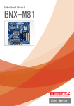
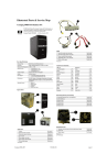
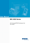
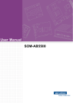
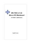
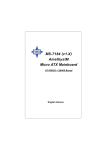
HP Business Desktop dx5150
Series Personal Computer
Illustrated Parts Map
Small Form Factor
© 2005, 2006 Hewlett-Packard Development Company, L.P.
HP and the HP logo are trademarks of Hewlett-Packard
Development Company, L.P.
All other product names mentioned herein may be trademarks of
their respective companies.
HP shall not be liable for technical or editorial errors or
omissions contained herein. The information in this document is
provided “as is” without warranty of any kind and is subject to
change without notice. The warranties for HP products are set
forth in the express limited warranty statements accompanying
such products. Nothing herein should be construed as
constituting an additional warranty.
Second Edition June 2006
First Edition April 2005
Document Number
361683-002
Mass Storage Devices (not illustrated)
40 GB\7200 RPM SATA hard drive
365555-001*⌧
409232-001
80 GB\7200 RPM SATA hard drive
345713-005*⌧
413319-001
160 GB\7200 RPM SATA hard drive
345712-005*⌧
391741-001
1250 GB\7200 RPM SATA hard drive
391937-001
Diskette drive
333505-005*⌧
392415-001
48X CD-ROM drive
326773-005*⌧
391730-001
52X CD-ROM drive
333969-005*⌧
413522-001
48X/32X/48X CD-RW
346788-005*⌧
397130-001
48X/32X/48X +16X DVD/CD-RW
359493-005*⌧
405425-001
48X/32X/48X CDRW
394382-001*⌧
395272-001
16X DVD+R/RW
381417-001*⌧
405760-001
16/40X DVD ROM Drive
325313-005*⌧
405761-001
Zip 250 drive with mounting bracket
333504-005*⌧
Media card reader
407187-001
Miscellaneous Parts
Standard and Optional Boards
1
System board with alcohol pad and thermal grease
380132-001*⌧
409643-001
Memory Modules
System Unit
1
Heatsink with thermal grease and alcohol pad
383171-001*⌧
409816-001
2
Chassis fan
383178-001*⌧
409817-001
3
Processor backing plate
383179-001*⌧
410278-001
4
Speaker
383176-001⌧
410291-001
#
Mouse, 2-Button, PS/2 with scroll wheel
323614-005*⌧
390937-001
#
Mouse, 2-Button, USB, optical with scroll wheel
323615-005*⌧
390939-001
#
Mouse, 2-Button, USB, with scroll wheel
323617-005*⌧
390938-001
349988-005*⌧
#
128 MB/400 MHz FSB
335697-005*⌧
#
256 MB/400 MHz FSB
335698-005*⌧
407309-001
#
Drive Key, 128 MB
#
Drive Key, 256 MB
372889-001*⌧
#
Real-time-clock battery
153099-001
#
Feet, rubber, 4 oval, 4 round
370708-001
#
512 MB/400 MHz FSB
335699-005*⌧
410810-001
#
1.0 GB/400 MHZ FSB
335700-005*⌧
407311-001
1
Access panel
383172-001*⌧
410277-001
2
Chassis assembly
not spared
3
Front bezel
383173-001
#
1.8 GHz\1.0 GHz FSB, 512 KB cache, 3000+
383165-001*⌧
4
Power supply, 200 W, PFC
376648-001*⌧
409815-001
#
2.0 GHz\1.0 GHz FSB, 512 KB cache, 3200+
383166-001*⌧
5
Diskette drive bezel
364508-001
#
2.2 GHz\512 KB cache, 3400+
411136-001
Miscellaneous screw kit, including:
6
Diskette drive bezel blank
337019-001
#
Bezel blank, 5.25-inch
335937-005
337237-005
#
2.2 GHz\1.0 GHz FSB, 512 KB cache, 3500+
383167-001*⌧
412689-001
#
2.4 GHz\1.0 GHz FSB, 512 KB cache, 3800+
383168-001*⌧
412690-001
Countersunk, flat head plastite (247481-001) 2 ea
#
Dual core, 1MB cache, 3800+
404361-001
#
2.4 GHz\1.0 GHz FSB, 1 MB cache, 4000+
383292-001*⌧
412692-001
#
Dual core, 1MB cache, 4200+
411415-001
#6-32 x .312, hitop, speaker (192308-002) 4 ea
M3 x 5mm, hitop (263585-001) 4 ea
#6-32 x .250, hitop (262508-001) 8 ea
#6-32 x .250, pan head (101517-067) 3 ea
#6-32 x .312, hitop (262508-002) 4 ea
AMD Sempron processors with alcohol pad and thermal grease
#6-19 x .312, pan head (101346-068) 2 ea
#
1.8 GHz, 256 KB cache, 3200+
383169-001*⌧
405798-001
#6-19 x .315, T15 head (331310-001) 2 ea
#
1.8 GHz, 128 KB cache, 3000+
383170-001*⌧
404362-001
#
256K, 3500+
411137-001
Keyboards (not illustrated)
PS/2, Basic
USB, Basic
USB, Modular
USB SmartCard
355630-xxx*⌧ 382925-xx1
355631-xxx*⌧ 382927-xx1
355102-xxx*⌧ 382926-xx1
373670-xx1
#
TPM security module
366504-001*⌧
#
PCI Modem, International, FH bracket
361286-021*⌧
#
PCI Modem, International, LP bracket
361287-021*⌧
Brazilian Portuguese
-205
Japanese
-295
#
Broadcom Gigabit NIC, LP bracket
367853-001*⌧
Europe#
-025
LA Spanish
-165
#
Agere 2006 PCI 56K Soft Modem, LP/FH bracket
398661-001
French Canadian
-125
PRC
-AA5
#
Intel Pro 10/100/1000 MT NIC, LP bracket
338154-005*⌧
International##
-B35
U.S.
-005
#
Intel Pro 1000GT Gigabit NIC, LP brackets
413889-001
#
Intel Pro 1000 PT Gigabit NIC, LP bracket
398754-001
#For 355102 only
##Not for 355102
FireWire 1394 card, 2 ext/1 int port, LP bracket
361551-001*⌧
393307-001
Notes:
⌧ Original Spare
Modified Spare
REQUIREMENT:
For customers in countries/regions with RoHS legislation* (e.g. EU,
China, etc.) restricting the use of hazardous substances in electrical
equipment.
The use of the Original Spare part is regulated by RoHS legislation. If your
unit contains a part that is labelled with the Modified Spare number, the
Modified Spare must be ordered as the replacement part.
If your unit contains a part that is labelled with the Original Spare number,
please order the Original Spare as the replacement part. In this case either
the Original Spare or the Modified Spare may be shipped which will not
affect performance or functionality of the unit.
*Directive 2002/95/EC restricts the use of lead, mercury, cadmium,
hexavalent chromium, PBBs and PBDEs in electronic products. Countries/
regions outside the EU, e.g. China, are introducing similar legislation. References to ‘RoHS legislation’ means requirements of Directive 2002/95/EC
or similar substance restrictive legislation enacted by any country/region
outside the EU. or similar substance restrictive legislation enacted by any
country/region outside the EU.
1
SATA hard drive cable, 10”
346143-005*⌧
392307-001
#
2
Power switch, LED cable
337243-005*⌧
407303-001
Wireless LAN adapters (802.11b)
#
14 channel, LP bracket, for Japan
356296-295
3
Front audio cable
383177-001*⌧
410283-001
#
14 channel, LP bracket, international
356296-B35
4
Com port cable (379443-001)
383287-001*⌧
410279-001
#
*
SATA hard drive cable (alternate), 14”
346144-001*⌧
391740-001
ATI Radeon X300 VGA graphics card, 128MB, LP
bracket, FH bracket
361266-001*⌧
398332-001
#
Diskette drive cable, 14.5” (143218-008)
383174-001*⌧
410282-001
ATI Radeon X300 VGA graphics card, 64MB, LP
bracket, FH bracket
361267-001*⌧
*
#
UATA data cable, 11” (108950-056)
383175-001*⌧
410285-001
ATI Radeon X1300 VGA graphics card, 256MB, LP
bracket, FH bracket
413023-001
*
*Not shown
Miscellaneous Screw Kit (not illustrated)
#6-32 x .250, hitop, taptite (192308-001) 4 ea
Other Cards
Cables
*Not shown
AMD Athlon processors with alcohol pad and thermal grease
Graphics Solutions
# Not shown
LP = Low profile mounting bracket
FH = Full height mounting bracket
Keyboard Diagnostic LEDs, PS/2 Keyboards Only
LED
Color
LED Activity
State/Message
Num Lock
Green
On
ROMPaq diskette or ROMPaq CD not present,
is bad, or drive not ready.
Caps Lock
Green
On
Enter password.
Num, Caps,
Scroll Lock
Green
Blink on in sequence, one at a
time—N, C, SL
Keyboard locked in network mode.
Num, Caps,
Scroll Lock
Green
On
Boot Block ROM Flash successful. Turn power
off, then on to reboot.
* Diagnostic lights do not flash on USB keyboards.
Clearing CMOS Using Computer Setup
The computer's configuration (CMOS) stores password information and information about the computer’s configuration.
To clear and reset the configuration, perform the following procedure:
This is the preferred method for clearing CMOS. However, if you cannot access Computer Setup,
refer to the next section for instructions on using the CMOS switch to clear CMOS.
1. Turn on or restart the computer. If you are in Microsoft Windows, click Start > Shut Down > Restart.
2. As soon as the computer is turned on, press and hold the F10 key until you enter Computer Setup.
✎
System Board Connectors and Jumpers (position of some untitled components may vary in location)
ATX1
Main power connector (24 pin)
AUD1
Front I/O panel audio
JTPM1
TPM security module
✎
3.
4.
If you do not press F10 at the appropriate time, you must restart the computer and press and hold
F10 until you enter Computer Setup.
Use the arrow keys to select Load Optimized Defaults, then press Enter.
To apply and save changes, press F10, or select Save & Exit Setup and press Enter.
JUSB1
Front USB connector
AUX_IN1 Aux audio in
PCI1
PCI socket 1
BAT1
Battery
PCI2
PCI socket 2
Clearing CMOS Using the CMOS Switch
CD_IN1
CD audio in
PCIE1X1
PCI Express x1 connector
The computer's configuration (CMOS) may occasionally be corrupted. If it is, it is necessary to clear the CMOS
memory using switch SW2.
To clear and reset the configuration, perform the following procedure:
1. Prepare the computer for disassembly.
CHASSIS_ System fan
FAN
PCIE16X1 PCI Express x16 connector
COM1
SATA1
SATA drive
CPU_FAN Processor fan
Flying serial port
SATA2
SATA drive
CPU1
Processor socket
SPKR
Internal audio
F_P1
Hood sensor
SW2
CMOS switch
FDD1
Diskette drive
XMM1
Memory socket
IDE1
IDE drive connector
XMM2
Memory socket
J4
Boot block (default = off)
XMM3
Memory socket
J5
Password enable (default = off)
XMM4
Memory socket
JPW1
4-pin aux power connector
System Hardware Interrupts
IRQ
System Function
IRQ
System Function
0
Reserved, Timer Interrupt
12
Onboard Mouse Port
1
Reserved, Keyboard Buffer Full Coprocessor
13
Reserved, Numeric Port
4
Serial Port (COM 1)
14
Primary (IDE) Controller
5
PCI System Management
15
Secondary (IDE) Controller
6
Diskette Drive Controller
19
Integrated Graphics (GPU)
8
Real-Time Clock Controller
21
Integrated Audio/USB Host
9
ACPI Compliant System
22
Network Interface Card (NIC)
Computer Diagnostic LEDs (on front of computer)
LED
Color
LED/Beep Activity
State/Message
Power
Green
On
(S0) Computer on
Power
Green
1 blink every 2 seconds
(S1) Suspend Mode
Power
Green
1 blink every 2 seconds
(S3) Suspend to RAM
Power
Red*
2 blinks and beeps 1 second
apart
CPU thermal shutdown
Power
Red*
3 blinks and beeps 1 second
apart
CPU not installed
Power
Red*
4 blinks and beeps 1 second
apart
Power supply overload.
Power
Red*
5 blinks and beeps 1 second
apart
Pre-video memory error.
Power
Red*
6 blinks and beeps 1 second
apart
Pre-video graphics card error
Power
Red*
7 blinks 1 and beeps second
apart
System board failure (detected prior to video)
Power
Red*
8 blinks and beeps 1 second
apart
Invalid ROM checksum
Power
Red*
9 blinks and beeps 1 second
apart
System power on but is unable to boot.
Hard Drive
Green
Blinking
Hard drive activity
*Blinking codes are repeated after a two second pause. Beeps stop after fifth iteration, but LEDs continue until problem
is resolved.
Ä
2.
3.
4.
5.
CAUTION: You must disconnect the power cord from the power source before sliding the Clear CMOS
switch (NOTE: All LEDs on the board should be OFF). The CMOS switch will not clear CMOS if the
power cord is connected.
Remove the access panel.
Slide the CMOS button located on the system board and hold it for 5 seconds.
Replace the access panel.
Turn the computer on and run F10 Computer Setup (Setup Utility) to reconfigure the system.
Disabling or Clearing the Power-On and Setup Passwords
1.
2.
3.
4.
5.
6.
7.
8.
9.
Turn off the computer and any external devices, and disconnect the power cord from the power outlet.
With the power cord disconnected, press the power button again to drain any residual power from the computer.
Remove the access panel.
Locate the header and green jumper labeled J5.
Remove the jumper from pins 1 and 2. Place the jumper over either pin 1 or pin 2, but not both, to avoid losing it.
Replace the access panel.
Plug in the computer and turn on power. Allow the operating system to start, which clears current passwords and
disables the password features.
To re-enable the password features, repeat steps 1-3, then replace the jumper on pins 1 and 2.
Repeat steps 6-8, then establish new passwords in Computer Setup.
Refer to the Computer Setup (F10 Setup) instructions to establish new passwords.
Computer Setup (F10) Utility Features (not all features may be available)
System
Information
Displays
Standard
CMOS
Features
Date
Time
PATA IDE Channel 0 Master
PATA IDE Channel 1 Master
PATA IDE Channel 2 Master
Drive A
Floppy 3 Mode Support
Halt On
POST Delay
Advanced
BIOS
Features
Removable Device Boot
Priority
Hard Disk Boot Priority
CD-ROM Boot Priority
Network Boot Priority
MBR Security
Quick Power On Self Test
First Boot Device
Second Boot Device
Third Boot Device
Fourth Boot Device
Boot Up NumLock Status
APIC Function
MPS Version Control for OS
HDD S.M.A.R.T. Capability
BIOS Write Protection
Internal Video Mode
AGP Aperture Size
UMA Frame Buffer Size
Video Display Devices
Auto Detect PCI Clk
Spread Spectrum
Integrated
Peripherals
South OnChip IDE Device
South OnChip PCI Device
Init Display First
Surroundview
OnChip USB Controller
Front Panel USB Port
Onboard FDC Controller
Onboard Serial Port
Onboard Parallel Port
Parallel Port Mode
ECP Mode Use DMA
Power
Management
Setup
ACPI Function
ACPI Suspend Type
After AC Power Loss
PowerOn by PCI Card
AMD Cool’n’Quiet
RTC Alarm Resume
Date (of Month)
Resume Time
PnP/PCI
Configuration
Reset Configuration Data
Resources Controlled By
IRQ Resource
PCI/VGA Palette Snoop
Assign IRQ for VGA
Assign IRQ for USB
PC Health
Status
System Information
Load Optimized Defaults
Set Supervisor Password
Set User Password
Save & Exit Setup
Exit Without Saving
Advanced
Chipset
Features