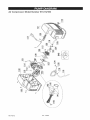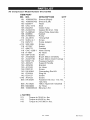
1
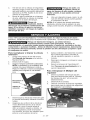
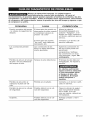
Owner's
Manual
Permanently
Lubricated
Tank Mounted
AiR COMPRESSOR
=
Safety Guidelines
=
Assembly
=
Operation
=
Maintenance
=
Service
=
Troubleshooting
=
Repair
and Adjustments
Parts
CAUTION:
Read the Safety Guidelines
and All Instructions Carefully Before
Operating.
Sears, Roebuck
and Co., Hoffman
Visit our Craftsman
N01 421 2 Rev,
0 7/24/08
Estates,
IL 60179 U.S.A.
website: www.sears.com/craftsman
WARRANTY ................................................
SPECiFiCATiON CHART ......................................
SAFETY GUiDELiNES - DEFiNiTiONS ...........................
2
3
3
iMPORTANT SAFETY iNSTRUCTiONS ........................
GLOSSARY ................................................
ACCESSORIES .............................................
DUTY CYCLE ...............................................
ASSEMBLY ...............................................
INSTALLATION .........................................
3-9
9
9
9
10
10-11
OPERATION ............................................
MAINTENANCE .........................................
SERVICE AND ADJUSTMENTS ............................
STORAGE ................................................
TROUBLESHOOTING ....................................
REPAIR PARTS .........................................
ESPA_IOL ..............................................
12-14
14-15
15-16
16
17-19
20-23
24-41
REPAIR PROTECTION AGREEMENT ...........................
HOW TO ORDER REPAIR PARTS ......................
43
back cover
ONE YEAR FULL WARRANTY
If this product fails due to a defect in material or workmanship within one year
from the date of purchase, Sears will at its option repair or replace it free of
charge. Contact Sears at 1-800-4-MY-HOME ® to arrange for repair, or return it
to the place of purchase for replacement.
If this product is used for commercial or rental purposes, this warranty applies
for only ninety days from the date of purchase.
This warranty gives you specific legal rights and you may have other rights
which vary from state to state.
Sears, Roebuck and Co., Dept. 817WA, Hoffman Estates, IL 60179
N014212
2 - ENG
Model No.
919.152160
Running HP
Bore
Stroke
Voltage-Single Phase
Minimum Branch Circuit Requirement
Fuse Type
Air Tank Capacity
Approx. Cutqn
Approx. Cut-out
SCFM @ 40 PSIG
SCFM @ 90 PSlG
0.8*
1-7/8"
1-1/4"
120V
10 amps
Time Delay
6 gallon
120 PSi
150 PSI
3.7*
2.6*
*Tested per ISO 1217
Refer to Glossary for abbreviations.
This manual contains information that is important for you to know and understand. This information relates to protecting YOUR SAFETY and PREVENTING
EQUIPMENT PROBLEMS. To help you recognize this information, we use the
symbols below. Please read the manual and pay attention to these symbols.
_
Indicates an
imminently hazardous
situation which, if not avoided, will
result in death or serious inNury.
_
ndicates a situation
potentially
hazardous
which, if not avoided, could result in
death or serious injury_.
_
ndicates a situation
potentially
hazardous
which, if not avoided, _
result in
minor or moderate injury.
Used without the
safety alert symbol
indicates a potentially hazardous
situation which, if not avoided, may
result in property damaq#_.
reproductive
This product contains chemicals known to the State of
California to cause cancer, and birth defects or other
harm. Wash hands after handling.
reproductive
Some dust contains chemicals known to the State
of California to cause cancer, birth defects or other
harm such as asbestos and lead in lead based paint.
Do not operate this unit until you read and
"__"
understand this instruction manual for safety,
operation and maintenance instructions.
_A
SAVE THESE INSTRUCTIONS
3 - ENG
N014212
' °_ _
RISK OF EXPLOSION OR FiRE
WHAT CAN HAPPEN
HOW TO PREVENT iT
=
It is normal for electrical contacts
within the motor and pressure
switch to spark,
=
Always operate the compressor in a
well ventilated area free of combustible materials, gasoline, or solvent
vapors.
•
If electrical sparks from compressor
come into contact with flammable
vapors, they may ignite, causing fire
or explosion.
•
If spraying flammable materials,
locate compressor at least 20 feet
(6.1 m) away from spray area. An
additional length of air hose may be
required.
Store flammable materials in a
secure location away from compressor.
Never place objects against or on
top of compressor.
Operate compressor in an open
area at least 12" (30.5 cm) away
from any wall or obstruction that
would restrict the flow of fresh air to
the ventilation openings.
Operate compressor in a clean, dry
well ventilated area. Do not operate
unit indoors or in any confined area.
Always remain in attendance with
the product when it is operating.
Always turn off and unplug unit
when not in use.
Restricting any of the compressor
ventilation openings will cause serious overheating and could cause
fire.
•
Unattended operation of this product could result in personal injury
or property damage. To reduce the
risk of fire, do not allow the compressor to operate unattended.
__
RiSK TO BREATHING (ASPHYXiATiON)
WHAT CAN HAPPEN
HOW TO PREVENT iT
The compressed air directly from
your compressor is not safe for
breathing. The air stream may
contain carbon monoxide, toxic
vapors, or solid particles from the
air tank. Breathing these contaminants can cause serious injury or
death.
N014212
4 - ENG
Air obtained directly from the compressor should never be used to
supply air for human consumption.
In order to use air produced by this
compressor for breathing, suitable
filters and in-line safety equipment
must be properly installed. In-line
filters and safety equipment used
in conjunction with the compressor must be capable of treating air
to all applicable local and federal
codes prior to human consumption.
Exposure to chemicals in dust created by power sanding, sawing,
grinding, drilling, and other construction activities may be harmful.
Sprayed materials such as paint,
paint solvents, paint remover, insecticides, weed killers, may contain
harmful vapors and poisons.
__
•
Work in an area with good cross
ventilation. Read and follow the
safety instructions provided on the
label or safety data sheets for the
materials you are spraying. Always
use certified safety equipment:
NIOSH/OSHA respiratory protection or properly fitting face mask
designed for use with your specific
application.
RISK OF BURSTING
Air Tank: The air tank on your Air Compressor is designed and may be UM coded
(for units with air tanks greater than 6" (122 mm) diameter) according to ASME
Section VIII, Div. 1 rules. All pressure vessels should be inspected once every two
years. To find your state pressure vessels inspector, look under the Division of Labor
and Industries in the government section of a phone book.
The following conditions could lead to a weakening of the air tank, and result in a
violent air tank explosion:
WHAT CAN HAPPEN
HOW TO PREVENT IT
Failure to properly drain condensed
water from air tank, causing rust
and thinning of the steel air tank.
Drain air tank daily or after each
use. If air tank develops a leak,
replace it immediately with a
new air tank or replace the entire
corn pressor.
Modifications or attempted repairs
to the air tank.
Never drill into, weld, or make any
modifications to the air tank or its
attachments. Never attempt to
repair a damaged or leaking air
tank. Replace with a new air tank.
Unauthorized modifications to
the safety valve or any other
components which control air tank
pressure,
Attachments
•
•
The air tank is designed to
withstand specific operating
pressures. Never make adjustments
or parts substitutions to alter the
factory set operating pressures.
•
Follow the equipment
manufacturers recommendation
and never exceed the maximum
allowable pressure rating of
attachments. Never use compressor
to inflate small low pressure objects
such as children's toys, footballs,
basketballs, etc.
& accessories:
Exceeding the pressure rating of
air tools, spray guns, air operated
accessories, tires, and other
inflatables can cause them to
explode or fly apart, and could
result in serious injury.
5 - ENG
N014212
Tires:
*
Over inflation of tires could result in
serious injury and property damage,
*
Use a tire pressure gauge to check
the tires pressure before each use
and while inflating tires; see the tire
sidewall for the correct tire pressure.
NOTE: Air tanks, compressors and similar equipment used to inflate tires can fill
small tires similar to these very rapidly.
Adjust pressure regulator on air supply to
no more than the rating of the tire pressure. Add air in small increments and frequently use the tire gauge to prevent over
inflation.
RIsK
oFELECTRICAL
SHOCK
WHAT CAN HAPPEN
•
HOW TO PREVENT iT
Your air compressor is powered by
electricity. Like any other electrically
powered device, If it is not used
properly it may cause electric
shock.
•
Repairs attempted by unqualified
personnel can result in serious
injury or death by electrocution.
Electrical Grounding: Failure to
provide adequate grounding to
this product could result in serious
injury or death from electrocution.
Refer to Grounding Instructions
paragraph in the Installation
section.
N014212
6 - ENG
Never operate the compressor
outdoors when it is raining or in wet
conditions.
Never operate compressor with
protective covers removed or
damaged.
Any electrical wiring or repairs
required on this product should be
performed by authorized service
center personnel in accordance with
national and local electrical codes.
Make certain that the electrical
circuit to which the compressor
is connected provides proper
electrical grounding, correct voltage
and adequate fuse protection.
__
RiSK FROM FLYING OBJECTS
WHAT CAN HAPPEN
o
HOW TO PREVENT IT
The compressed air stream can
cause soft tissue damage to
exposed skin and can propel dirt,
chips, loose particles, and small
objects at high speed, resulting in
property damage or personal injury.
=
•
Always wear certified safety equipment: ANSI Z87.1 eye protection
(CAN/CSA Z94.3) with side shields
when using the compressor.
Never point any nozzle or sprayer
toward any part of the body or at
other people or animals.
Always turn the compressor off
and bleed pressure from the air
hose and air tank before attempting maintenance, attaching tools or
accessories.
RiSK
OFHOT
SURFACES
WHAT CAN HAPPEN
•
_r_
HOW TO PREVENT IT
Touching exposed metal such as
the compressor head, engine head,
engine exhaust or outlet tubes, can
result in serious burns.
__
•
R,SK FROM MOV,NG PARTS
WHAT CAN HAPPEN
•
Never touch any exposed metal
parts on compressor during or
immediately after operation.
Compressor will remain hot for
several minutes after operation.
Do not reach around protective
shrouds or attempt maintenance
until unit has been allowed to cool.
HOW TO PREVENT IT
Moving parts such as the pulley, flywheel, and belt can cause serious
injury if they come into contact with
you or your clothing.
•
Attempting to operate compressor
with damaged or missing parts or
attempting to repair compressor
with protective shrouds removed
can expose you to moving parts
and can result in serious injury.
7 - ENG
Never operate the compressor with
guards or covers which are damaged or removed.
Keep your hair, clothing, and gloves
away from moving parts. Loose
clothes, jewelry, or long hair can be
caught in moving parts.
Air vents may cover moving parts
and should be avoided as well.
Any repairs required on this product
should be performed by authorized
service center personnel.
N014212
[__
RiSK OF UNSAFE OPERATION
WHAT CAN HAPPEN
•
HOW TO PREVENT iT
Unsafe operation of your air compressor could lead to serious injury
or death to you or others.
•
Review and understand all instructions and warnings in this manual.
Become familiar with the operation
and controls of the air compressor.
Keep operating area clear of all persons, pets, and obstacles.
Keep children away from the air
compressor at all times.
Do not operate the product when
fatigued or under the influence of
alcohol or drugs. Stay alert at all
times.
Never defeat the safety features of
this product.
Equip area of operation with a fire
extinguisher.
Do not operate machine with missing, broken, or unauthorized parts.
•
RiskOFFALLING
WHAT CAN HAPPEN
•
HOW TO PREVENT IT
A portable compressor can fall
from a table, workbench, or roof
causing damage to the compressor and could result in serious
injury or death to the operator.
•
_
Always operate compressor in a
stable secure position to prevent
accidental movement of the unit.
Never operate compressor on a
roof or other elevated position.
Use additional air hose to reach
high locations.
m D
' ""
"
RiSK FROM NOISE
WHAT CAN HAPPEN
Under some conditions and duration of use, noise from this product
may contribute to hearing loss.
•
HOW TO PREVENT IT
Always wear certified safety equipment: ANSI S12.6 (S3.19) hearing
protection.
SAVE THESE INSTRUCTIONS
FOR FUTURE USE
N014212
8 - ENG
Become familiar with these terms
before operating the unit.
CFM: Cubic feet per minute.
SCFM: Standard cubic feet per minute; a unit of measure of air delivery.
PSIG: Pounds per square inch gauge;
a unit of measure of pressure.
Code Certification:
Products that
bear one or more of the following
marks: UL, CUL, ETL, CETL, have
been evaluated by ©SHA certified
independent safety laboratories and
meet the applicable Underwriters
Laboratories Standards for Safety.
Cut-in Pressure: While the motor
is off, air tank pressure drops as you
continue to use your accessory. When
the tank pressure drops to a certain
low level the motor will restart automatically. The low pressure at which
the motor automatically restarts is
called "cut-in" pressure.
Cut-Out Pressure: When an air compressor is turned on and begins to
run, air pressure in the air tank begins
to build. It builds to a certain high
pressure before the motor automatically shuts off, protecting your air tank
from pressure higher than its capacity.
The high pressure at which the motor
shuts off is called "cut-out" pressure.
Branch Circuit: Circuit carrying electricity from electrical panel to outlet.
This unit is capable of powering the following accessories. The accessories are
available through the current Power and Hand Tool Catalog or full-line Sears
stores.
Accessories
Refer to the selection chart located on
the unit to select the tools this unit is
•
In Line Filter
capable of powering.
Tire Air Chuck
Quick Connector Sets
_The
use of any
-other accessory
(various sizes)
not recommended for use with
Air Pressure Regulators
this tool could be hazardous. Use
Oil Fog Lubricators
only accessories rated equal to
Air Hose: 1/4", 3/8" or 1/2" I.D. in
or higher than the rating of the air
various lengths
compressor.
This air compressor pump is capable
of running continuously. However, to
prolong the life of your air compressor,
it is recommended that a 50%-75%
average duty cycle be maintained;
that is, the air compressor pump
should not run more than 30-45
minutes in any given hour.
9 - ENG
N014212
Unpacking
1. Remove unit from carton and discard all packaging.
HOW TO SET UP YOUR UNiT
Location of the Air Compressor
•
Locate the air compressor in a
clean, dry and well ventilated
area.
•
The air compressor should be
located at least 12" (30.5 cm)
away from the wall or other
obstructions that will interfere
with the flow of air.
=
The air compressor pump and
shroud are designed to allow for
proper cooling. The ventilation
openings on the compressor are
necessary to maintain proper
operating temperature. Do not
place rags or other containers on
or near these openings.
GROUNDING
2.
Make sure the outlet being used
has the same configuration as the
grounded plug. DO NOT USE AN
ADAPTER. See illustration.
3.
Inspect the plug and cord before
each use. Do not use if there are
signs of damage.
If these grounding instructions are
not completely understood, or if in
doubt as to whether the compressor is properly grounded, have the
installation checked by a qualified
electrician.
4.
INSTRUCTIONS
_Risk
of Electrical
Shock. In the event
of a short circuit, grounding reduces
the risk of shock by providing an
escape wire for the electric current.
This air compressor must be
properly grounded.
The portable air compressor is
equipped with a cord having a
grounding wire with an appropriate
grounding plug (see following
illustrations).
Risk of Electrical
Shock. iMPROPER
GROUNDING CAN RESULT IN
ELECTRICAL SHOCK.
Do not modify the plug provided, if
it does not fit the available outlet, a
correct outlet should be installed by
a qualified electrician.
Repairs to the cord set or plug
MUST be made by a qualified electrician.
1.
The cord set and plug with this
unit contains a grounding pin.
This plug MUST be used with a
grounded outlet.
iMPORTANT: The outlet being used
must be installed and grounded in
accordance with all local codes and
ordinances.
N014212
10-ENG
Extension
Cords
If an extension cord must be used, be
sure it is:
•
a 3-wire extension cord that has
a 3-blade grounding plug, and a
3-slot receptacle that will accept
the plug on the product
in good condition
no longer than 50 feet
14 gauge (AWG) or larger. (Wire
size increases as gauge number
decreases. 12 AWG and 10 AWG
may also be used. DO NOT USE
16 OR 18 AWG.)
The
use of an
-undersized
extension cord will cause voltage to
drop resulting in power loss to the
motor and overheating. Instead of
using an extension cord, increase
the working reach of the air hose by
attaching another length of hose to its
end. Attach additional lengths of hose
as needed.
Voltage and Circuit Protection
Refer to the specification chart for the
voltage and minimum branch circuit
requirements.
Risk of Opertion.
-Certain air
compressors
can be operated on
a 15 amp circuit if the following
conditions are met.
1.
Voltage supply to circuit must
comply with the National
Electrical Code.
2. Circuit is not used to supply any
other electrical needs.
3. Extension cords comply with
specifications.
4. Circuit is equipped with a 15 amp
circuit breaker or 15 amp time
delay fuse. NOTE: If compressor
is connected to a circuit protected
by fuses, use only time delay
fuses. Time delay fuses should be
marked "D" in Canada and "T" in
the US.
If any of the above conditions cannot
be met, or if operation of the compressor repeatedly causes interruption
of the power, it may be necessary to
operate it from a 20 amp circuit. It is
not necessary to change the cord set.
11 - ENG
N014212
Know Your Air Compressor
READ THIS OWNER'S MANUAL AND SAFETY RULES BEFORE OPERATING
YOUR UNIT. Compare the illustrations with your unit to familiarize yourself with
the location of various controls and adjustments. Save this manual for future
reference.
Safety Valve
Description
of Operation
Become familiar with these controls
before operating the unit.
On(I)/Off(O) Switch: Place this switch
in the On (I) position to provide
automatic power to the pressure
switch and Off (O) to remove power at
the end of each use.
Pressure Switch (not shown): The
pressure switch automatically starts
the motor when the air tank pressure
drops below the factory set "cut-in"
pressure. It stops the motor when the
air tank pressure reaches the factory
set "cut-out" pressure.
Safety Valve: If the pressure switch
does not shut off the air compressor
at its "cut-out" pressure setting, the
safety valve will protect against high
pressure by "popping out" at its
factory set pressure (slightly higher
than the pressure switch "cut-out"
setting).
Tank Pressure Gauge: The tank
pressure gauge indicates the reserve
air pressure in the tank.
Outlet Pressure Gauge: The outlet
pressure gauge indicates the air
pressure available at the outlet side
of the regulator. This pressure is
N014212
controlled by the regulator and is
always less than or equal to the tank
pressure.
Regulator: Controls the air pressure
shown on the outlet pressure
gauge. Turn regulator knob
clockwise to increase pressure
and counterclockwise
to decrease
pressure.
Cooling System (not shown): This
compressor contains an advanced
design cooling system. At the heart of
this cooling system is an engineered
fan. It is perfectly normal for this fan
to blow air through the vent holes
in large amounts. You know that the
cooling system is working when air is
being expelled.
Air Compressor Pump (not shown):
Compresses air into the air tank.
Working air is not available until the
compressor has raised the air tank
pressure above that required at the air
outlet.
Drain Valve:
The drain valve
is located at
Drain
the base of the Valve
air tank and is
used to drain
condensation at the end of each use.
12-ENG
Check Valve: When the air
compressor is operating, the check
valve is "open", allowing compressed
air to enter the air tank. When the
air compressor reaches "cut-out"
pressure, the check valve "closes",
allowing air pressure to remain inside
the air tank.
3.
Motor Overload Protector (not
shown): The motor has an automatic
reset thermal overload protector. If
the motor overheats for any reason,
the overload protector will shut off the
motor. The motor must be allowed
to cool down before restarting. The
compressor will automatically restart
after the motor cools.
Before Each Start=Up
1. Set the On/Off switch to "Off".
2. Turn the regulator knob counterclockwise to set the outlet
pressure to zero.
3. Attach hose and accessories.
Open the drain valve (counterclockwise) fully to permit air to
escape and prevent air pressure
build up in the air tank during the
break-in period.
4. Move the On/Off switch to "On"
position. The compressor will start.
5. Run the compressor for 15 minutes. Make sure the drain valve
is open and there is minimal air
pressure build-up in tank.
6. After 15 minutes, close the drain
valve by turning clockwise. The
air receiver will fill to "cut-out"
pressure and the motor will stop.
The compressor is now ready for use.
NOW TO USE YOUR UNiT
How to Stop
1. Set the On/Off switch to "Off".
Before
_Risk
of unsafe
operation. Firmly
grasp air hose in hand when
installing or disconnecting
to
prevent hose whip.
Starting
use damaged
Do not operate this
unit until you read
and understand this instruction
manual for safety, operation and
maintenance instructions.
Break=in Procedure
Risk of Unsafe
-Operation. Serious
damage may result if the following
break=in instructions are not closely
followed.
This procedure is required before the
air compressor is put into service and
when the check valve or a complete
compressor pump has been replaced.
1. Make sure the On/Off switch is in
the "Off" position.
2. Plug the power cord into the
correct branch circuit receptacle.
(Refer to Voltage and Circuit
Protection paragraph in
the Installation section of
this manual.)
Risk of unsafe
operation. Do not
or worn accessories.
NOTE: The hose or accessory will
require a quick connect plug if the air
outlet is equipped with a quick connect socket.
Risk of Bursting.
Too much air
pressure causes a hazardous risk of
bursting. Check the manufacturer's
maximum pressure rating for air
tools and accessories. The regulator
outlet pressure must never exceed
the maximum pressure rating.
Risk of unsafe
operation.
Compressed air from the unit may
contain water condensation
and
oil mist. Do not spray unfiltered air
at an item that could be damaged
by moisture. Some air tools and
accessories may require filtered
air. Read the instructions for the air
tools and accessories.
13-ENG
N014212
How to Start:
1. Set the On/Off switch to "On"
and allow tank pressure to build.
Motor will stop when tank pressure
reaches "cut-out" pressure.
2. Turn regulator knob clockwise to
increase pressure and stop when
desired pressure is reached.
Customer
lf any unusual
noise or vibration
is noticed, stop the compressor
immediately and have it checked by
a trained service technician.
The compressor is ready for use.
Responsibilities
Before
each
use
Daily
or after
each
use
Check Safety Valve
X
Drain Tank
X
_Unit
cycles
-automatically
when
power is on. When performing
maintenance, you may be exposed
to voltage sources, compressed air,
or moving parts. Personal injuries
can occur. Before performing any
maintenance or repair, disconnect
power source from the compressor
and bleed off all air pressure.
NOTE: See Operation section for the
location of controls.
To Check
Safety
Valve
3.
4.
_Risk
from Flying
__
Objects. Always
wear certified safety equipment:
ANSI Z87.1 eye protection (CAN/OSA
Z94.3) with side shields
Before starting compressor, pull
the ring on the safety valve to
make sure that the safety valve
operates freely. If the valve
is stuck or does not operate
smoothly, it must be replaced with
the same type of valve.
N014212
Risk of Unsafe
Operation. Risk
from noise. Air tanks contain high
pressure air. Keep face and other
body parts away from outlet of
drain. Use ANSI Z87.1 eye protection
(CAN/OSA Z94.3) when draining as
debris can be kicked up into face.
Use ear protection [(ANSI S12.6
($3.19)] hearing protection) as air
flow noise is loud when draining.
1.
2.
_Risk
of Bursting.
-if the safety valve
does not work properly, over=
pressurization
may occur, causing
air tank rupture or an explosion.
1.
To Drain Tank
5.
Set the On/Off switch to "Off".
Turn the regulator knob counterclockwise to set the outlet
pressure to zero.
Remove the air tool or accessory.
Pull ring on safety valve allowing
air to bleed from the tank until
tank pressure is approximately
20 PSI. Release safety valve ring.
Drain water from air tank by
opening drain valve on bottom of
tank.
Risk of Bursting.
Water will condense
in the air tank. If not drained, water
will corrode and weaken the air tank
causing a risk of air tank rupture.
14 - ENG
NOTE: If drain valve is plugged,
release all air pressure. The valve
can then be removed, cleaned, the
reinstalled.
Risk of Property
Damage. Drain
water from air tank may contain oil
and rust which can cause stains.
6.
After the water has been drained,
close the drain valve. The air
compressor can now be stored.
ALL MAINTENANCE
AND REPAIR OPERATIONS
PERFORMED BY TRAINED SERVICE TECHNICIAN.
NOT LISTED MUST
BE
Risk of Unsafe Operation. Unit cycles automatically
when
power is on. When servicing, you may be exposed to
voltage sources, compressed air, or moving parts. Before servicing unit
unplug or disconnect electrical supply to the air compressor, bleed tank of
pressure, and allow the air compressor to cool.
To Replace or Clean Check
Valve
1. Release all air pressure from air
tank. See To Drain Tank in the
Maintenance section.
2. Unplug unit.
3. Remove the hose by removing
the hose clamp. NOTE: The hose
clamp is not reusable. You must
purchase a new hose clamp,
see the Parts List or purchase a
standard hose clamp at a local
hardware store.
6.
7.
8.
Apply sealant to the check valve
threads. Reinstall the check valve
(turn clockwise).
Replace hose and new hose
clamp.
Perform the Break-in Procedure.
See Break-in Procedure in the
Operation section.
To Replace Regulator
Manifold
1. Release all air pressure from air
tank. See To Drain Tank in the
Maintenance section.
2. Unplug unit.
3. Using an adjustable wrench
remove the safety valve from the
regulator manifold.
Hose
Clamp
Check
Valve
4.
5.
Unscrew the check valve (turn
counter-clockwise) using a socket
wrench.
Make sure the valve disc moves
freely inside the check valve and
the spring holds the disc in the
upper, closed position. The check
valve may be cleaned with a
solvent, such as paint and varnish
remover.
15-ENG
N014212
4.
Remove the hose by removing
the hose clamp. NOTE: The hose
clamp is not reusable. You must
purchase a new hose clamp,
see the Parts List or purchase a
standard hose clamp at a local
hardware store.
6.
Carefully slide pump from
brackets and out of the way.
Pump
shown
moved out
of the way
Regulator
Manifold
Regulator
Manifold
7.
5.
Remove pump mounting screws
securing pump (one on each side).
Pump Mounting
Screw
Before you store the air compressor,
make sure you do the following:
1. Review the Maintenance section
on the preceding pages and
perform scheduled maintenance
as necessary.
2. Set the On/Off switch to "Off" and
unplug unit.
3. Turn the regulator counterclockwise and set the outlet pressure to
zero.
4. Remove the air tool or accessory.
5. Pull ring on safety valve allowing
air to bleed from the tank until
tank pressure is approximately
20 PSI. Release safety valve ring.
6. Drain water from air tank by
opening drain valve on bottom of
tank.
N014212
Using an adjustable wrench
remove the regulator manifold.
8. Apply pipe sealant to new
regulator manifold and assemble,
tighten with wrench.
9. Reapply pipe sealant to safety
valve.
10. Reassemble all components in
reverse order of removal. Make
sure to orient gauges to read
correctly and use wrenches to
tighten all components.
Risk of Bursting.
Water will condense
in the air tank. if not drained, water
will corrode and weaken the air tank
causing a risk of air tank rupture.
7.
After the water has been drained,
close drain valve by turning
clockwise.
NOTE: If drain valve is plugged,
release all air pressure. The valve
can then be removed, cleaned, then
reinstalled.
8.
9.
16-ENG
Protect the electrical cord and
air hose from damage (such as
being stepped on or run over).
Wind them loosely around the
compressor handle.
Store the air compressor in a
clean and dry location.
Risk of Unsafe Operation. Unit cycles automatically
when
power is on. When servicing, you may be exposed to
voltage sources, compressed air, or moving parts. Before servicing unit
unplug or disconnect electrical supply to the air compressor, bleed tank of
pressure, and allow the air compressor to cool.
PROBLEM
CAUSE
CORRECTION
Excessive tank pressure
- safety valve pops off.
Pressure switch does
not shut off motor when
compressor reaches
"cut-out" pressure.
Move On/Off lever to
the "Off" position, if
the outfit does not shut
off contact a Trained
Service Technician.
Pressure switch "cutout"too high.
Contact a Trained
Service Technician.
Air leaks at fittings.
Tube firings are nottight
enough.
Tighten fittings where air
can be heard escaping.
Check fittings with
soapy water solution. Do
Not Overtighten.
Air leaks in air tank or at
air tank welds.
Defective air tank.
Air tank must be
replaced. Do not repair
the leak.
Risk bursting. Do
not drill into, weld or
otherwise modify air
tank or it will weaken.
The tank can rupture
or explode.
Air leaks between head
and valve plate.
Leaking seal.
Air leak from safety
valve.
Possible ddectin
valve.
safety
Operate safety valve
manually by pulling on
ring. If valve still leaks, it
should be replaced.
Knocking Noise.
Possible defect in safety
valve.
Operate safety valve
manually by pulling on
ring. If valve still leaks, it
should be replaced.
17 - ENG
Contact a Trained
Service Technician.
N014212
PROBLEM
CAUSE
CORRECTION
Pressure reading on
the regulated pressure
gauge drops when an
accessory is used.
It is normal for "some"
pressure drop to occur.
If there is an excessive
amount of pressure drop
when the accessory
is used, adjust the
regulator following
the instructions in
the Description of
Operation paragraph in
the Operation Section.
NOTE: Adjust the
regulated pressure under
flow conditions (while
accessory is being
used).
Compressor is not supplying enough air to
operate accessories.
Prolonged excessive use
of air.
Decrease amount of air
usage.
Compressor is not large
enough for air requirement.
Check the accessory
air requirement. If it is
higher than the SCFM
or pressure supplied
by your air compressor,
you need a larger
compressor.
Hole in hose.
Check and replace if
required.
Check valve restricted.
Remove and clean, or
replace.
Air leaks.
Tighten fittings.
Damaged regulator.
Replace.
Regulator knob has continuous air leak.
N014212
18-ENG
PROBLEM
CAUSE
CORRECTION
Regulator will not shut
off air outlet.
Damaged regulator.
Replace.
Motor will not run.
Fuse blown, circuit
breaker tripped.
Check fuse box
for blown fuse and
replace as necessary.
Reset circuit breaker.
Do not use a fuse or
circuit breaker with
higher rating than
that specified for your
particular branch circuit.
Check for proper fuse.
You should use a time
delay fuse.
Check for low voltage
problem.
Check the extension
cord.
Disconnect the other
electrical appliances
from circuit or operate
the compressor on its
own branch circuit.
Extension cord is wrong
length or gauge.
Check the extension
cord.
Loose electrical
connections.
Check wiring
connection inside
terminal box.
Faulty motor.
Have checked by
a Trained Service
Technician.
Motor overload protection switch has tripped
Refer to Motor
Overload Protection
under Operation.
If motor overload
protection trips
frequently, contact
a Trained Service
Technician.
19-ENG
N014212
Air Compressor
Model Number
PARTS
919.152160
SHOWN
FOR REFERENCE
ONLY
34
36;
4
28
4
t
856
N014212
N014212
Air Compressor
= MODEL
20 - ENG
NUMBER
919.15216
07/31/08
Air Compressor
Model Number
ITEM PART
NO. NO.
2
3
4
5
7
8
9
10
11
18
19
24
28
31
32
33
34
35
36
D24721
91895680
SSF-621
A14877
A17038
A17987
1000002226
A16182
A17166
A19714
CAC-1254
LA-3109
LA-3108
LA-3270
LA-2876
1000003194
N014220
A17135
1000002886
919.152160
DESCRiPTiON
QTY
Isolator Kit
Screw
Screw
Nipple
Drain Valve
Safety Valve
Manifold (incl. 5, 10, 11,35)
Quick Connect Body
Gauge
Check Valve
Pump Isolator
Drain Tank Warning Label
Hot Surface Label
Warning Label
Power Cord Label
Identification Label
Nameplate
Gauge
Rating Label
21 - ENG
3
3
2
1
1
1
1
2
1
1
4
1
1
1
1
1
1
1
1
N014212
Air Compressor
N014212
Model Number
919.152160
22 - ENG
Air Compressor
Model Number
iTEM PART
NO. NO.
101
102
103
104
105
106
107
108
109
110
e113
114
_115
116
117
118
119
120
121
121
122
123
124
125
128
140
141
142
0143
846
1000002791
1000002792
D25877
CAC-1212
D22253
Z-D24819
Z-A08548
A03865
Z-A04615
AC-0815
SUDL-9-1
D25731
SSF-995
Al1027
A04770
CAC-1206-1
H-7051
SSF-3156
Z-D23825
Z-D27196
N002119
A00470
A05239
A10162
D29132
KK-4964
D30324
D21127
A19123
KK-4929
856 AC-0625
856 N004086
856 1000000543
919.152160
DESCRIPTION
QTY
Shroud (Right)
Shroud (Left)
Head
Seal
Outlet Tube
Gasket Kit (Incl. 104)
Valve Plate Assembly
Gasket
Pump
Timing Belt
Screw
Pump Isolator
Screw
Switch
Cordset
Hose Clamp
Air Hose
Screw
Brush Motor (Ametek)
Brush Motor (Gold Tuning)
Pressure Switch
Support Handle
Bracket
Air Hose
Screw
Connecting Rod Kit
Ring Kit
Screw
Screw
Fastener Kit (Incl. 113,115,
128,143)
Teflon Tape(not included)
Air Hose
BlowGun Kit
1
1
1
1
1
1
1
1
1
1
1
5
4
1
1
4
1
1
1
1
1
1
1
1
5
1
1
1
1
1
1
1
1
¢ NOTES:
113
Torque to 30-45 in.-Ibs.
115
Torque to 49-55 in.-Ibs.
143
Torque to 315-385 in.qbs.
23 - ENG
N014212
GARANTIA .......................................................
CUADRO DE ESPEClFICAClONES
DEFINICIONES
DE NORMAS
IMPORTANTES
INSTRUCClONES
24
...................................
DE SEGURIDAD
25
..........................
25
DE SEGURIDAD ....................
25-31
GLOSARIO .......................................................
31
ACCESORIOS
31
....................................................
ClCLO DE SERVlClO
..............................................
ENSAMBLAGE
....................................................
INSTALAClON
..................................................
OPERAClON
34-36
...............................................
Y REGULAClONES
ALMACENAJE
36-37
....................................
37-38
....................................................
GUIA DE DIAGNOSTICO
CONTRATOS
32
32-33
...................................................
MANTENIMIENTO
SERVlClOS
31
DE PROBLEMAS
DE PROTECClON
38
...........................
PARA REPARAClONES ..................
LISTA DE PARTES ...............................................
COMO SOLIClTAR
39-41
PIEZAS PARA REPARAClON
43
20-23
.................
contratapa
GARANTJA TOTAL DE UN ANO
Siesta unidad fallase debido a defectos de materiales o de fabricaci6n dentro
del ado de su fecha de compra, Sears, a su opci6n, Io reparar& o reemplazara
sin costo alguno. Comuniquese con Sears al 1-800-4-MY-HOME ® para coordinar su reparaci6n, o devuelva la unidad al lugar donde Io compr6 para que Io
cambien.
Siesta unidad se usase con fines comerciales o para alquiler, esta garantia se
aplica s61o durante los primeros noventa dias a partir de su fecha de compra
Esta garantia le otorga derechos especificos y usted podria tener otros derechos que varian de un estado a otro.
Sears, Roebuck and Co., Dept. 817WA, Hoffman
N014212
24- SP
Estates, IL 60179
Modelo N °
Potencia de trabajo
Diametro interior
Carrera
Voltaje-corriente manofAsica
Circuito minimo requerido
Tipo de fusible
Capacidad de aire en el tanque
Presi6n de corte de entrada
Presi6n de corte de salida
SCFM a 40 PSIG
SCFM a 90 PSIG
919.152160
*0,8 HP
1-7/8 pulg. (47,6 mm)
1-1/4 pulg. (31,8 mm)
120V
10A
Acci6n retardada
6 Galones (22,7 litros)
120 PSI
150 PSI
*3,7 Calibre de libras pot pulgada cuadrada
*2,6 Calibre de libras pot pulgada cuadrada
*Probado segun la norma ISO 1217
Refi6rase al glosario para descifrar
las abreviaturas.
Este manual contiene informaci6n que es importante que usted conozca y comprenda. Esta
informaci6n se relaciona con la protecci6n de SU SEGURIDAD y LA PREVENCION DE
PROBLEMAS A SU EQUIPO. Para ayudarlo a reconocer esta informaci6n, usamos los
simbolos indicados mAs abajo. Sirvase leer el manual y prestar atenci6n a estas secciones.
Indica una situaci6n de
riesgo inminente, que si
no se evita, causarA la rnuerte o lesiones
serias,
Ilndica una situaci6n
potencialmente
peligrosa, que si no se evita, puede causar
lesiones menores o moderadas.
Indica una
:
"
situaci6n
potencialmente riesgosa, que si no se
evita, podria causar la rnuerte o lesiones
serias,
Usado sin el simbolo de
_
seguridad de alerta indica
una situaci6n potencialmente riesgosa la
que, si no se evita, podria causar da_os
en la propiedad.
_
_Este
producto contiene sustancias quirnicas, incluido el piorno,
reconocidas
por el Estado de California como causantes de
cancer, defectos de nacimiento u otros problemas reproductivos.
Lavese las manos
despu_s de utilizarlo.
_
AIgunos tipos de polvo contienen sustancias quirnicas, como el
amianto y el plomo de las pinturas de base plomo, reconocidas
por el Estado de California como causantes de cancer, defectos
otros problemas
de nacimiento
La operaci6n o el mantenimiento inadecuados deeste
-producto podrian ocasionar lesiones serias y daSos a la
propiedad. Lea y comprenda todas las advertencias e instrucciones de
funcionamiento antes de utilizar este equipo.
CONSERVE
u
I Wl
ESTAS INSTRUCCIONES
25 - SP
N014212
RIESGO
_QU_ = PUEDE
DE EXPLOSION
SUCEDER?
0 INCENDIO
COMO
EVITARLO
•
Es normal que los contactos el6ctricos
dentro del motor y el interruptor de
presi6n produzcan chispas,
•
Opere siempre el compresor en un
&rea bien ventilada libre de materiales
combustibles, gasolina o vapores de
solventes.
•
Si las chispas el6ctricas del compresor entran en contacto con vapores
inflamables, pueden encenderse, provocando un incendio o una explosi6n.
•
Si se pulverizan materiales inflamables,
ubique el compresor al menos a 6,1 m
(20 pies) del Area de pulverizaci6n. Se
puede necesitar manguera adicional.
Guarde los materiales inflamables en
lugar seguro lejos del compresor.
•
Restringir cualquiera de las aberturas
de ventilaci6n del compresor puede
producir un sobrecalentamiento grave
y podria provocar un incendio.
Nunca coloque objetos contra o sobre
el compresor.
Opere el compresor en un lugar abierto con una distancia de al menos
30,5 cm (12 pulg.) a cualquier pared u
obstrucci6n que pudiera restringir el
flujo de aire fresco alas aberturas de
ventilaci6n.
Opere el compresor en un Area limpia,
seca y bien ventilada. No opere la
unidad dentro de la casa o en un Area
muy cerrada.
•
El funcionamiento sin atenci6n de este
producto podria provocar lesiones personales o da_os a la propiedad. Para
disminuir el riesgo de incendio, no
permita que el compresor funcione sin
que alguien Io controle.
la uni-
II
RIESGO RESPIRATORIO
(ASFIXlA)
COMO EVITAR LO
&QUE PUEDE SUCEDER?
El aire comprimido que sale de su
compresor no es seguro para respirarlo. El flujo de aire puede contener
mon6xido de carbono, vapores t6xicos o particulas s61idas del tanque
de aire. Respirar estos contaminantes puede provocar lesiones graves
o la muerte.
N014212
Siempre apague y desenchufe
dad cuando no est6 en uso.
i
m
_
Permanezca siempre controlando el
producto cuando estA en funcionamiento.
26 - SP
El aire que se obtiene directamente
del compresor no se debe usar
nunca para consumo humano. Para
poder utilizar el aire producido por
este compresor para respirar, se
deben instalar correctamente filtros
y equipos en linea adecuados. Los
filtros y los equipos de seguridad en
linea que se usan junto con el compresor deben set capaces de tratar
el aire segQn todos los c6digos
locales y federales antes de que
sea consumido por seres humanos.
•
La exposici6n a productos quimicos
en el polvo producido por las herramientas electricas al lijar, aserrar,
esmerilar, taladrar y otras actividades de la construcci6n puede ser
peligrosa.
Los materiales pulverizados como
pintura, solventes para pinturas,
removedor de pintura, insecticidas y herbicidas pueden contener
vapores da_inos y venenos.
Trabaje en un _.rea con buena
ventilaci6n
cruzada. Lea y siga las
instrucciones
de seguridad
que se
proveen en la etiqueta o en la ficha
t6cnica de los materiales
que esta
utilizando. Siempre
utilice equipamiento
de seguridad
certificado:
protecci6n
respiratoria
aprobada
pot NIOSH!OSHA
o una mascarilla
facial adecuada
dise_ada
para usar
para los fines que usted requiere.
" o
__
RIESGO DE EXPLOSION
Tanque de aire: El tanque de aire de su compresor de aire esta diseSado y puede
tener c6digo UM (para unidades con tanques de aire de m&s de 152 mm (6 pulgadas)
de diametro) segQn las normas de la ASME, Secci6n VIII, Div. 1. Todos los recipientes de
presi6n se deben inspeccionar cada dos aSos. Para encontrar al inspector de recipientes
de presi6n de su estado, busque en la Divisi6n Trabajo e Industrias de la secci6n gubernamental de la guia telef6nica para obtener ayuda.
Las siguientes condiciones podrian Ilevar a un debilitamiento del tanque de aire, y provocar una explosi6n violenta del tanque:
_QUE
PUEDE
SUCEDER?
COMO
EVITARLO
•
No drenar correctamente el agua
condensada del tanque de aire, que
provoca 6xido y adelgazamiento del
tanque de aire de acero.
•
Modificaciones o intento de reparaci6n
del tanque de aire.
•
Nunca perfore, suelde o haga ninguna
modificaci6n al tanque de aire o a sus
elementos. Nunca intente reparar un
tanque de aire daSado o con perdidas.
Reempl&celo con un tanque de aire
nuevo.
•
Las modificaciones no autorizadas de
la v&lvula de seguridad o cualquier otro
componente que controle la presi6n
del tanque,
•
El tanque esta diseSado para soportar
determinadas presiones de operaci6n.
Nunca realice ajustes ni sustituya
piezas para cambiar las presiones de
operaci6n fijadas en la f&brica.
o
Siga la recomendacion del fabricante
del equipo y nunca exceda el nivel
maximo de presi6n aceptable para los
elementos. Nunca utilice el compresor
para inflar objetos pequeSos de baja
presi6n, tales como juguetes de niSos,
pelotas de fQtbol o de basquetbol, etc.
Elementos
Drene el tanque diariamente o luego
de cada uso. Si un tanque de aire
presenta una perdida, reemplAcelo
inmediatamente con un tanque nuevo
o reemplace todo el compresor.
y accesorios:
Exceder las indicaciones de presi6n
para las herramientas neum&ticas, las
pistolas pulverizadoras, los accesorios
neum&ticos, los neum&ticos y otros
articulos inflables puede hacer que
exploten o revienten, y puede provocar
lesiones graves.
27 - SP
N014212
Neum_ticos:
•
El inflado excesivo de los neumaticos podria causar lesiones graves
y da_o a la propiedad.
Utilice un medidor de presi6n de
neumAticos para controlar la presi6n
de estos antes de cada uso y mientras
los infla; observe el flanco para ver la
presi6n correcta del neumAtico.
NOTA: Los tanques
de aire, los compresores y el equipo similar que se usa
)ara inflar neumaticos
pueden
Ilenar
neumb, ticos peque_os
come 6stos con
mucha rapidez. Ajuste el regulador
de
)resi6n en el suministro
de aire a un
valor que no supere
el de la presi6n
del neumatico.
Agregue
aire en forma
gradual y use con frecuencia
el medidor
de presi6n de neum_.ticos
para evitar
inflarlos.
m
[_-_
RIESGO
&QUE
•
_
PUEDE
0
DE DESCARGA
ELECTRICA
COMO
SUCEDER?
Su compresor de aire funciona con
electricidad. Como cualquier otro
mecanismo que funciona con electricidad, si no se Io utiliza correctamente
puede provocar descargas el6ctricas.
•
EVITAR LO
Nunca haga funcionar el compresor al
aire libre cuando esta Iloviendo o en
condiciones de humedad.
Nunca haga funcionar el compresor
sin las cubiertas de protecci6n o si
estan da_adas.
Que personal no calificado intente
realizar reparaciones puede provocar
lesiones graves o muerte pot electrocuci6n.
Cualquier cableado el6ctrico o las
reparaciones requeridas para este
producto deben ser realizadas por
un centro de servicio de un centro de
mantenimiento autorizado de acuerdo
con los c6digos el6ctricos nacionales
y locales.
Puesta a tierra: La no colocaci6n de
la puesta a tierra adecuada para este
producto puede provocar lesiones
graves o muerte por electrocuci6n.
Consulte las Instrucciones de
Conexi6n a tierra en Instalacidn.
AsegOrese de que el circuito el6ctrico
al que se conecta el compresor suministre la conexi6n a tierra adecuada, el
voltaje adecuado y el fusible de protecci6n adecuado.
N014212
28 - SP
__
RIESGO DE OBJETOS DESPEDIDOS
COMO
&QUa: PUEDE SUCEDER?
•
La corriente de aire comprimido
puede provocar lesionesen los
tejidos blandos de la piel expuesta
y puede impulsar suciedad, astillas,
particulas sueltas y objetos pequenos a gran velocidad, que pueden
producir danos en la propiedad y
lesiones personales.
•
EVITAR LO
Utilice siempre equipo de seguridad
certificado: anteojos de seguridad
ANSI Z87.1(CAN/CSA Z94.3)con protecci6n lateral al usar el compresor.
Nunca apunte ninguna boquilla ni pulverizador a ninguna parte del cuerpo o
a otras personas o animales.
Apague siempre el compresor y drene
la presi6n de la manguera de aire y del
tanque de aire antes de intentar hacer
mantenimiento, conectar herramientas
o accesorios.
e
__
RIESGO
&QUE
PUEDE
DE SUPERFICIES
COMO
SUCEDER?
Tocar metal expuesto como el cabezal
del compresor, el cabezal del motor,
el escape del motor, o los tubos de
salida puede provocar quemaduras
graves.
i
•
CALIENTES
EVITAR LO
Nunca toque ninguna parte metalica
expuesta del compresor durante o
inmediatamente despues de su funcionamiento. El compresor continuara caliente durante varios minutos
despu6s de su funcionamiento.
No toque las cubiertas protectoras ni
intente realizar mantenimiento hasta
que la unidad se haya enfriado.
•
RIESGO
PORPIEZAS
M6VlLES
&QUE
=
PUEDE
SUCEDER?
COMO
Las piezas m6viles como la polea, el
volante y la correa pueden provocar
lesiones graves si entran en contacto
con usted o con sus ropas.
=
EVITARLO
Nunca haga funcionar el compresor
sin los protectores o cubiertas o si los
mismos estan daSados.
Mantenga el cabello, la ropa y los
guantes alejados de las piezas en
movimiento. Las ropas holgadas, las
joyas o el cabello largo pueden quedar
atrapados en las piezas m6viles.
Los orificios de ventilaci6n pueden
cubrir piezas en movimiento, pot Io
que tambi6n se deben evitar.
Intentar hacer funcionar el compresor
con pares daSadas o faltantes, o
intentar reparar el compresor sin las
cubiertas protectoras puede exponerlo
a piezas m6viles Io que puede provocar lesiones graves.
29- SP
Cualquier reparaci6n requerida por
este producto debe ser realizada pot
un centro de servicio de un centro de
servicio autorizado.
N014212
_]_
RIESGO DE OPERACION INSEGURA
_,QUE PUEDE
•
SUCEDER?
COMO
La operaci6n insegura de su compresor de aire podria producir lesiones
graves o la muerte, a usted mismo o a
otras personas,
•
•
EVITARLO
Revise y comprenda todas las instrucciones y advertencias de este manual.
Familiaricese con la operaci6n y los
controles del compresor de aire.
Mantenga el Area de operaciones libre
de personas, mascotas y obstaculos.
Mantenga a los ni_os alejados del
compresor de aire en todo momento.
No opere el producto cuando est6
cansado o bajo la influencia de alcohol
o drogas. Mant6ngase alerta en todo
momento.
Nunca anule las caracteristicas de
seguridad de este producto.
Equipe el Area de operaciones con un
extintor de incendios.
No opere la mAquina si faltan piezas,
si 6stas estan rotas o si no son las
autorizadas.
" 0
RIEsGoDECAiDAS
&QU! _ PUEDE
COMO
SUCEDER?
Un compresor portatil se puede caer
de una mesa, banco o techo, provocando da_os al compresor y puede
producir lesiones graves o la muerte
del operador.
m
' "
&QUE
'
PUEDE
" '
•
EVITAR LO
Opere siempre el compresor en una
posici6n estable y segura para evitar
que la unidad se mueva accidentalmente. Nunca opere el compresor
sobre un techo u otra ubicaci6n
elevada. Utilice una manguera de aire
adicional para alcanzar las ubicaciones
elevadas.
0
•
RESGOPORRUIDOS
SUCEDER?
COMO
En determinadas condiciones y segQn
el periodo de uso, el ruido provocado
por este producto puede originar p6rdida de audici6n.
•
EVITARLO
Utilice siempre equipo de seguridad
certificado: protecci6n auditiva ANSI
$12.6 ($3.19).
CONSERVE ESTAS INSTRUCCIONES
PARA FUTURAS CONSULTAS
N014212
30 - SP
Familiaricese con los siguientes
terminos, antes de operar la unidad:
CFM: (Cubic feet per minute) Pies cObicos
por minuto.
SCFM: (Stardard cubic feet per minute)
Pies cObicos est&ndar por minuto; una
unidad de medida que permite medir la
cantidad de entrega de aire.
PSIG: (Pound per square inch) Libras por
pulgada cuadrada.
C6digo de certificaci6n:
Los productos
que usan una o m&s de las siguientes
marcas: UL, CUL, ETL, CETL, han sido
evaluados por OSHA, laboratorios
independientes certificados en seguridad,
y reOnen los estandares suscriptos por los
laboratorios dedicados a la certificaci6n de
la seguridad.
Presi6n minima de corte: Cuando el motor
esta apagado, la presi6n del tanque de aire
baja a medida que usted continQa usando
su accesorio. Cuando la presi6n del
tanque baja al valor fijado en f&brica como
punto bajo, el motor volver& a arrancar
autom&ticamente. La presi6n baja a la cual
el motor arranca autom&ticamente, se llama
presi6n "minima de corte".
Presi6n rn_xirna de corte: Cuando un
compresor de aire se enciende y comienza
a funcionar, la presi6n de aire en el tanque
comienza a aumentar. Aumenta hasta un
valor de presi6n alto fijado en f&brica
antes de que el motor autom&ticamente se
apague protegiendo a su tanque de aire de
presiones m&s altas que su capacidad.
La
presi6n alta a la cual el motor se apaga se
llama presi6n "m&xima de corte".
Rarnal: Circuito el6ctrico que transporta
electricidad desde el panel de control hasta
el tomacorriente.
Esta unidad es suficiente para abastecer de energia el6ctrica a los siguientes accesorios.
Estos se encuentran disponibles a trav6s del catAlogo para herramientas el6ctricas y manuales, en cualquiera de los comercios que mantiene la linea completa de SEARS.
Accesorios
• Filtro de intercalar
Refi6rase al grafico de selecci6n ubicado
sobre la unidad, para elegir el tipo de herramienta que esta unidad es capaz de
hacer funcionar.
• Boquilla para inflar cubiertas.
• Juego de conexion rapida
(varias medidas)
I___
--
• Reguladores de presi6n de aire.
• Lubricadores para niebla de aceite.
• Manguera de aire:
1/4 pulg., 3/8 pulg. o 1/2 pulg. DI. en distintas
longitudes.
Esta bomba compresora de aire es
capaz de funcionar continuamente, sin
embargo para prolongar la vida Qtil de
su compresor de aire se recomienda
mantener un ciclo promedio de servicio
El uso de
accesorios
no
recornendados
para utilizar con esta
herramienta
puede resuRtar peligroso.
Use
solamente
accesorios
con una capacidad
nominal
igual o superior
a la de la
compresor
de aire.
que oscile entre el 50% y el 75%; ello
significa que la bomba compresora no
deberia trabajar m&s de 30 a 45 minutos
por hora.
31 - SP
N014212
Desempaque
1. Extraiga la unidad de su caja y descarte todas las partes de embalaje.
COMO PREPARAR LA UNIDAD
2.
Ubicaci6n
del compresor
de aire
•
Ubicar el compresor de aire en un
lugar limpio, seco y bien ventilado.
El compresor de aire debe
colocarse alejado por Io menos
(30,5 cm) 12 pulg. de las paredes
o de cualquier otra obstrucci6n que
interfiera con el flujo de aire.
La bomba del compresor de aire y
su casco han sido dise_ados para
permitir un enfriamiento adecuado.
Las aberturas de ventilaci6n del
compresor son necesarias para el
mantenimiento de una temperatura
adecuada de funcionamiento. No
coloque trapos o contenedores,
encima, ni en las proximidades de
dichas aberturas.
Espiga
3.
4.
El compresor port&til de aire est& equipado
con un cable con un conductor y un
enchufe adecuado para conexi6n a tierra
(vea las siguientes ilustraciones).
1.
El cable de esta unidad tiene un
enchufe de 3 espigas para conexi6n
a tierra que DEBE enchufarse en un
tomacorriente conectado a tierra.
conexi6n
a tierra
Inspeccione el enchufe y su cord6n
antes de cada uso. No Io use si
existieran signos de danes.
Si las instrucciones de conexi6n
_
Riesgo
el_ctrico.de choque
LA CONEXION
INADECUADA A TIERRA PUEDE
CAUSAR UNA DESCARGA ELECTRICA.
No modifique el enchufe provisto. Si no
penetrara en el tomacorriente
disponible,
un electricista calificado debe instalar
uno apropiado.
La reparaci6n
DEBE hacerla
IMPORTANTE: El tomacorriente que
que se use debe estar conectado a
tierra conforme a todos los c6digos y
ordenanzas locales.
N014212
de
a tierra no fueran completamente
comprendidas, o si se estuviera ante
la duda acerca de que el compresor
estuviese adecuadamente
conectado
a tierra, haga verificar la instalaci6n
por un electricista competente.
INSTRUCClONES
PAPA
CONEOTAR A TIERRA
_
Riesgo de choque
-el_ctrico. Ante
la eventualidad de un cortocircuito, la
conexi6n a tierra reduce el riesgo de
electrocuci6n
proveyendo un conductor
de escape para la corriente el_ctrica.
Este compresor de aire debe estar
adecuadamente
conectado a tierra.
AsegOrese que el tomacorriente tenga
la misma configuraci6n que el enchufe
de conexi6n a tierra. NO UTIMCE UN
ADAPTADOR. Vea la figura.
32 - SP
del cable o del enchufe
un electricista calificado.
Cables de e×tensi6n
el_ctrica
Si - no obstante - debe utilizarse una extensi6n de cable, asegQrese de que:
•
La extensi6n el6ctrica de 3 conductotes, tenga un enchufe de conexi6n
a tierra de 3 hojas, y que exista un
receptaculo que acepte el enchufe del
producto.
•
Est6 en buenas condiciones.
•
No mas largo que 15,2 m (50 pies).
Sea calibre 14 (AWG) o mayor. (La
capacidad de los cables se incrementa
a medida que su nQmero ordinal decrece. Tambi6n pueden usarse calibres
12 y 10 AWG.
NO USE 16 NI 18
AWG).
_EI
uso de cables de
__
extensi6n el6ctrica
originarA una caida de tensi6n, Io que
determinarA una p6rdida de potencia del
motor asf como su recalentamiento. En
lugar de utilizar un cable de extensi6n
el_ctrica, incremente el alcance de la
manguera de aire dentro de la zona
de trabajo, a_adi_ndole otto largo de
manguera a su extremo. Conecte los
largos adicionales de manguera de
acuerdo a su necesidad.
Protecci6n
del voltaje y del circuito
Refi6rase a la cartilla de voltajes para
determinar los requisitos minimos que el
ramal del circuito requiere.
_
iesgo de Operaci6n
Insegura. Ciertos
compresores de aire pueden operearse
en un circuito de 15 A, siempre que se
cumplan las siguientes condieiones:
1.
Que el voltaje suministrado al ramal
cumpla con el c6digo el6ctrico
nacional.
2.
Que el circuito no sea utilizado para
alimentar ninguna otra necesidad
el6ctrica.
3.
Que los cables de extensi6n cumplan
con las especificaciones.
Que el circuito cuente con un
disyuntor de 15 amperios o un fusible
de acci6n retardada de 15 amperios.
NOTA" Si el compresor esta
conectado a un circuito protegido per
fusibles, use s61o fusibles de acci6n
retardada. Los fusibles de acci6n
retardada deben estar marcados
con la letra "D" en Canada y "T" en
EE.UU.
4.
Si cualquiera de las condiciones
enumeradas no pudiese cumplirse, o si
el funcionamiento del compresor causara
interrupciones reiteradas en el suministro
el6ctrico, podria set necesario operarlo
en un circuito de 20 amperios. Para ello
no sera necesario cambiar su cable de
limentaci6n.
33 - SP
N014212
Conozca
su compresor
de aire
LEA ESTE MANUAL DEL PROPIETARIO Y SUS NORMAS DE SEGURIDAD ANTES DE
OPERAR LA UNIDAD. Compare las ilustraciones contra su unidad a fin de familiarizarse
con la ubicaci6n de los distintos controles y regulaciones. Conserve este manual para referencias futuras.
Descripci6n
de operaciones
Familiaricese con estos controles antes de
operar la unidad.
Interruptor
Encendido (I) Apagado (O):
Para que el interruptor de presi6n se
energice automAticamente,
coloque
el interruptor en "Encendido" (I)yen
"Apagado" (O) para desenergizarlo al final
de cada uso.
Interruptor de presi6n (no rnostrado): El
interruptor de presi6n permite el arranque
autom_tico del motor cuando la presi6n del
tanque disminuye a la presi6n de arranque
regulada en fabrica. El motor se detendra
cuando la presi6n del tanque alcance la
"presi6n de corte" regulada en fabrica.
V_Jvula de seguridad: Si el interruptor
de presi6n dejara de cortar el suministro
de presi6n del compresor conforme a
los valores prefijados para la "presi6n de
corte", la valvula de seguridad proteger&
contra la presi6n elevada, "abri6ndose" a la
presi6n prefijada (ligeramente superior a la
"presi6n de corte".
Man6metro de la presi6n deJ tanque:
El man6metro que controla la presi6n del
tanque indica la reserva de presi6n del
tanque de aire.
Man6rnetro para controlar la presi6n
de salida. Este man6metro indicara la
presi6n de aire disponible a la salida del
regulador. Esta presi6n esta controlada pot
el regulador y siempre es menor o igual
que la presi6n del tanque.
N014212
Regulador: Controla la presi6n de aire
indicada en la salida del medidor de
presi6n. Gire la perilla del regulador en el
sentido del reloj para aumentar la presi6n y
contra el sentido del reloj para reducirla.
Sisterna de enfriamiento
(no mostrado}:
Este compresor contiene un sistema de
enfriamiento de avanzada. El n_cleo de
este sistema de enfriamiento contiene un
ventilador diseSado especialmente. Es
normal que este ventilador sople grandes
cantidades de aire pot los orificios de
ventilaci6n. Usted sabra que el sistema
de enfriamiento funciona adecuadamente
cuando perciba que sale aire.
Bornba de cornpresi6n deJ aire (no
rnostrada}: Comprime el aire dentro del
tanque. El aire de trabajo no se encuentra
disponible hasta que el compresor haya
alcanzado a Ilenar el tanque hasta un nivel
de presi6n pot encima del requerido para
la salida del aire.
V_ivula de
drenaje: La
v&lvula de
drenaje se
encuentra
ubicada en la
base del
tanque de aire y se usa para drenar la
condensaci6n al fin de cada uso.
34- SP
V_lvula de retenci6n: Cuando el compresor de aire se encuentra funcionando, la
valvula de retenci6n esta "abierta", permitiendo la entrada del aire comprimido al
tanque de aire. Cuando el nivel de presi6n
del tanque alcanza la "presi6n de corte", la
vAIvula de retenci6n "se cierra", reteniendo
la presi6n del aire dentro del tanque.
3.
4.
5.
6.
Protector de sobrecalentamiento
del
C6mo
1.
detenerla:
Apague colocando el interruptor
Encendido/Apagado
en "Apagado".
Haga funcionar el compresor durante
15 minutos. AsegOrese de que la
vAIvula de drenaje est6 abierta y que
la presi6n de aire acumulado en el
tanque sea minima.
Despues de 15 minutos, cerrar la v&lvula de drenaje girAndola en el sentido
del reloj. El tanque de aire se Ilenara
hasta alcanzar la presi6n de corte y el
motor se detendr&
Ahora el compresor esta listo para usarse.
motor (no mostrado): El motor tiene
un reposicionado autom&tico para la
protecci6n t6rmica. Si por cualquier raz6n
el motor se recalentara, el protector por
sobrecalentamiento Io detendr& El motor
debera dejarse enfriar antes de volver a
ponerlo en marcha. El compresor arrancar&
autom&ticamente luego que el motor se
enfrie.
COMO UTILIZAR SU UNIDAD
Abrir por completo (contra el sentido
del reloj) para dejar escapar aire y evitar que la presi6n del tanque aumente
durante el periodo de asentamiento.
Mueva el interruptor a la posici6n de
"encendido". El compresor se pondrA
en marcha.
Antes de cada puesta en marcha:
1.
2.
Apague colocando el interruptor
Encendido/Apagado
en "Apagado".
Gire la perilla del regulador contra el
sentido del reloj para regular la presi6n de la salida a cero.
3.
Conecte la manguera y accesorios.
_
Riesgo.de
operaclon
insegura. Sostenga la manguera
firmemente
con las manos al instalarla
o desconectarla
para evitar la
desconexi6n
repentina de la manguera.
Antes de poner en marcha
_
_No
opere esta
-unidad hasta
que haya leido y comprendido
este
manual de instrucciones de seguridad,
operacibn y mantenimiento.
insegura. No utilice
da_ados o usados.
Procedimiento
para
el asentamiento
Riesgo.de
operac|on
los accesorios
NOTA: Tanto la manguera como los
accesorios requerir&n un enchufe de
conexi6n r&pida si la salida del aire esta
equipada con un acople de conexiOn rapida.
_
_
iesgo de Operaci6n
Insegura. Si no se
siguen detalladamente
las instrucciones
para el asentamiento se pueden causar
daSos serios.
Este procedimiento es necesario antes
de poner en servicio al compresor de
aire, y cuando la valvula reguladora o la
bomba completa del compresor haya sido
reemplazada.
1.
Cerci6rese que el interruptor
Encendido/Apagado
est6 "Apagado".
2.
Enchufe el cable de alimentaci6n
en el tomacorriente del ramal del
circuito correcto. (Referirse al parrafo
Protecci6n
del voltaje y del
circuito en la secci6n Instalacidn de
este manual).
Riesgo de
Explosi6n.
Demasiada presi6n de aire podra ser la
causa de riesgo de explosi6n. Verifique
los valores de m_xima presi6n dados
pot el fabricante de las herramientas
neumaticas y los accesorios.
La presi6n
de salida del regulador jam_s debe
exceder los valores de m_xima presi6n
especificados.
35 - SP
N014212
C6mo poner en marcha:
1.
Coloque el interruptor Encendido/
Apagado en la posici6n de "Encendido"
y deje que se incremente la presi6n del
tanque. El motor se detendrA una vez
alcanzado el valor de presi6n "de corte"
del tanque.
2.
Gire la perilla del regulador en el sentido
del reloj para aumentar la presi6n
y det6ngase al alcanzar la presi6n
deseada.
_
iesgo de operacibn
insegura. El aire
comprimido
de la unidad puede
contener condensaci6n de agua y
emanaci6n de aceite. No pulverice
aire no filtrado sobre un articulo que
podrfa daSarse con la humedad.
AIgunos dispositivos
o herramientas
neumaticas pueden requerir aire
fiitrado. Lea las instrucciones del
dispositivo o la herramienta
neum_tica.
Si observa algQn
ruido o vibraci6n
inusuales, apague el compresor y contacte
a un t_cnico calificado en servicio.
Ahora el compresor est_ listo para usarse.
Responsabilidades
del cliente
Antes de
cada uso
Verifique la valvula
de seguridad
Diariamente
o luego de
cada
USO
X
Drenaje del tanque
X
_La
unidad
-arranea
automaticamente
cuando est_
conectada.
AI hacer et mantenimiento
puede quedar expuesto a fuentes de
voltaje, de aire comprimido
o a piezas
movibles que pueden causar lesiones
personales. Antes de intentar hacerle
cualquier mantenimiento,
desconecte
el compresor del suministro el_ctrico y
dr_nele toda la presi6n de aire.
NOTA: Vea en la secci6n Operacidn la
ubicaci6n de los controles.
C6mo
verificar
la v_lvula
de
seguridad
_
Riesgo de
Explosibn. Si
la valvula de seguridad no trabaja
adecuadamente,
ello podra determinar
la sobrepresi6n
del tanque, creando el
riesgo de su ruptura o explosi6n.
1.
C6mo
el tanque
Riesgo.de
operaclon insegura.
Riesgo por ruidos. Los tanques de aire
contienen aire de alta presi6n. Mantenga
la cara y otras partes del cuerpo lejos de
la salida del drenaje. Utiliceanteojos
de
seguridad ANSI Z87.1 (CAN/CSA Z94.3},
ya que al drenar se pueden desprender
residuos hacia la cara. Utilice proteccibn
auditiva ANSI S12.6 (S3.19), ya que el
ruido del flujo de aire es alto durante el
drenaje.
1.
_
N014212
drenar
_
2.
Riesgo de
objetos
despedidos. Utilice siempre equipo
de seguridad certificado: anteojos de
seguridad ANSI Z87.1 (CAN/CSA Z94.3)
con proteccibn lateral
Antes de poner en marcha el motor,
tire del anillo de la v&lvula de seguridad
para confirmar que opera libremente.
Si la v&lvula quedase trabada o no trabajara suavemente, debe reemplazarse
por el mismo tipo de v&lvula.
3.
36 - SP
Apague colocando el interruptor
Encendido/Apagado
en "Apagado".
Tire de la perilla del regulador y gire en
sentido contrario a las agujas de reloj
para establecer la salida de presi6n en
cero.
Desinstale la herramienta neum_tica o el
accesorio.
4.
5.
Tire del aro de la vAlvula de seguridad
dejando purgar el aire del tanque hasta
que este reduzca su presi6n aproximadamente a 20 PSI. Suelte el aro de la
valvula de seguridad.
Drene el agua contenida en el tanque
de aire, abriendo la valvula de drenaje
ubicada en la base del tanque.
del tanque se producira condensaci6n
de
agua. Si no drena, el agua Io corroer_ y
debilitara causando un riesgo de ruptura
del tanque de aire.
_
iesgo de daSo a la
propiedad. Drene el
agua del tanque de aire puede contener
aceite y 6xido, Io que puede provocar
manchas.
6.
Una vez drenada el agua, cierre la valvula de drenaje. Ahora puede guardar
el compresor de aire.
NOTA: Si la vAIvula de drenaje estuviese
obstruida, elimine toda la presi6n de aire.
Luego puede sacarla, limpiarla y reinstalarla.
TODO TIPO DE MANTENIMIENTO Y REPARACIONES NO MENCIONADOS EN ESTE
MANUAL, DEBERAN SER EFECTUADOS POR PERSONAL TECNICO ESPECIALIZADO.
_
Riesgo
de Operaci6n
Insegura.
La unidad arranca
autornaticamente
cuando
est_ enchufada.
AI hacer el
rnantenirniento,
el operador puede quedar expuesto a fuentes de corriente y de aire
cornprimido o a piezas movibles. Antes de intentar hacer reparaciones,
desconectar
el cornpresor del tornacorriente,
drenar la presi6n de aire del tanque y esperar a que
el compresor se enfrie.
Para reemplazar
retenci6n
o limpiar
6.
la v_lvula
1.
Libere toda presi6n de aire del tanque.
Vea Drenaje del tanque en la secci6n
Mantenimiento.
2.
3.
Desenchufe el equipo.
Saque la mangueraquitandole laabrazadera.
NOTA:La abrazaderano es reutilizable;debe
comprarotra nueva.Refierasea laLista de
Piezasen el Manualo compreuna abrazadera
estandar paramangueraen una ferreteria
local.
Abrazadera
7.
de
msRguera
8.
secci6n Operacidn.
3.
Desenrosque la valvula de retenci6n (gire
en sentido antihorario) utilizando una Ilave
tubular.
5.
AsegQrese que el disco de la valvula se
mueva libremente dentro de la valvula
reguladora y que el resorte sujete al
disco en posicbn erguida y cerrada. La
valvula reguladora puede ser limpiada
con solvente, tal como los utilizados para
pinturas y removedores de barniz.
Ejecute el proceso de "asentamiento".
Yea Proceso de asentamiento
en la
Para reemplazar
el MQItiple del
regulador
1.
Drene la presi6n del tanque de aire.
Vea las instrucciones para el "Drenaje
del tanque de aire" en la secci6n
Mantenimiento.
2.
Desenchufe la unidad.
V_lvula de
retenci6n
4.
Aplique sellador a los filamentos roscados
de la valvula reguladora. Reinstale la
valvula reguladora (girando en sentido
horario).
Reponga la manguera y coloque la nueva
abrazadera.
37 - SP
Usando una Ilave de tuercas regulable
para cada caso la v&lvula de seguridad
del regulador del mOltiple.
N014212
4.
Saquela manguera quitandole la
abrazadera. NOTA: La abrazadera
no es reutilizable; debe comprar otra
nueva. Refi6rase ala Lista de Piezas
en el Manual o compre una abrazadera
estandar para manguera en una ferreteria local.
6.
Saquela bomba de sus soportes
deslizAndola cuidadosamente.
Se muestra
con la
bomba
retirada
MQItiple dei
regulador
M_Jltiple del
regulador
7.
Saque los tornillos de montaje que
sujetan la bomba (uno en cada lado).
8.
9.
10.
Tornillo pare montaje
de la bomba
Antes de guarder su compresor de aire,
asegQrese de hacer Io siguiente:
1.
Revise la secci6n Mantenimiento de
las paginas precedentes y ejecute
el mantenimiento programado de
acuerdo ala necesidad.
I___
2.
7.
3.
4.
5.
6.
Riesgo de
Explosibn. El agua
se condensa dentro del tanque de aire.
Si no se drena, Io corroera debilitando la
paredes del tanque de aire, originando
un riesgo de ruptura de sus paredes.
Apague la unidad colocando el
interruptor Encendido/Apagado
en
posici6n "Apagado" y desenchQfela.
Gire el regulador en sentido antihorario
y fije la presi6n de salida en cero.
Extraiga la herramienta neumAtica o el
accesorio.
Tire del anillo de la v&lvula de
seguridad permitiendo el purgado del
aire del tanque haste que la presi6n
del mismo Ilegue aproximadamente a
20 PSI. Suelte el anillo de la vAIvula de
seguridad.
Drene el agua del tanque de aire
abriendo la valvula de drenaje ubicada
en el fondo del tanque.
N014212
Usando una Ilave de tuercas regulable
saque el mOltiple del regulador.
Aplique sellador para tuberias en el
nuevo mOltiple del regulador y ensamble ajustando con la Ilave.
Vuelva a aplicar sellador para tuberias
a la valvula de seguridad.
Re-ensamble todos los componentes
en orden inverso al que se sacaron.
AsegOrese de orientar los medidores
correctamente para que puedan leerse
y ajuste todos los componentes con
las Ilaves.
Cerrar la vAIvula de drenaje despues
de drenar toda el agua.
NOTA: Si la v&lvula de drenaje estuviese
obstruida, libere toda la presi6n de aire.
Luego puede sacarla, limpiarla y reinstalarla.
8.
Proteja el cable el6ctrico y las
mangueras de aire de da_os (tales
como ser pisoteados o pasados por
encima). Enr611elosen forma floja,
alrededor de la manija del compresor.
9.
Almacene el compresor de aire en un
sitio limpio y seco.
38 - SP
_
Riesgo de Operaci6n Insegura. La unidad arranca
automaticamente
cuando est_ enchufada. AI hacer el
mantenimiento,
el operador puede quedar expuesto a fuentes de corriente y de aire
comprirnido o a piezas rnovibles. Antes de intentar hacer reparaciones, desconectar
el compresor del tornacorriente,
drenar la presibn de aire del tanque y esperar a que
el compresor se enfrfe.
PROBLEMA
CAUSA
Presi6n excesiva del tanque
- la valvula de seguridad se
dispara.
El interruptor de presi6n no
interrumpe al motor cuando
el compresor alcanza la
3resi6n "de corte"
Mueva la palanca
Encendido/Apagado
a la
posici6n "Apagado", si el
equipo no corta, contacte a
un t6cnico calificado para el
servicio.
El interruptor de presi6n
"de corte" esta calibrado
demasiado alto.
Contacte a un t6cnico de
servicio calificado.
Las conexiones de los
tubos no estan suficientemente ajustadas.
Ajuste las conexiones en
las que el aire puede ser
escuchado
Las conexiones pierden
aire.
CORRECCION
escapandose. Verifique
las conexiones con soluci6n jabonosa y agua. No
sobreajuste.
P6rdida de aire en el tanque
de aire o en las soldaduras
del tanque de aire.
Tanque de aire defectuoso.
El tanque de aire debe ser
reemplazado. No repare la
perdida.
No efect_e perforaei6n
alguna sobre la soldadura
o cosa semejante sobre
el tanque de aire, ello
Io debilitate. El tanque
podria romperse o
explotar.
P6rdida de aire entre el
cabezal y el plato de v&lvula.
P6rdida en el sellado.
Contacte a un t6cnico calificado en servicio.
Perdida de aire en la v&lvula
de seguridad,
Posible defecto en la v&lvula de seguridad,
Opere la valvula de seguridad manualmente tirando
de su anillo. Si la valvula aun pierde, deber& set
reemplazada.
Golpeteo.
Posible defecto en la valvula de seguridad,
Extraiga y limpie o reemplace.
39 - SP
N014212
PROBLEMA
CAUSA
La lectura de la presi6n
sobre un man6metro desciende cuando se utiliza un
accesorio.
Es normal que ocurra alg_n
descenso en la presi6n.
Si hubiese una caida excesiva de presi6n durante el
uso del accesorio, ajuste
el regulador de acuerdo
alas instrucciones de la
Descripci6n de operaciones en la secci6n
Operacidn. NOTA: Ajuste
la presi6n regulada bajo
condiciones de flujo (mientras se est6 usando el
accesorio).
El compresor no esta suministrando suficiente cantidad de aire para operar los
accesorios.
Excesivo y prolongado
del aire.
Disminuya la cantidad de
uso de aire.
CORRECCION
uso
El compresor no tiene suficiente capacidad para el
requerimiento de aire al que
est& sometido.
Verifique el requerimiento
de aire del accesorio. Si
es mayor que SCFM o la
presi6n suministrada pot
su compresor de aire, se
necesita un compresor de
mayor capacidad.
Orificio en la manguera.
Verifique y reemplace si
fuese necesario.
V&lvula reguladora restringida.
Extraiga, limpie o
reemplace.
P6rdida de aire.
Ajuste las conexiones.
El regulador tiene una fuga
continua de aire.
Regulador dafiado.
Reemplace.
El regulador no cierra la
salida del aire.
Regulador dafiado.
Reemplace.
N014212
40 - SP
PROBLEMA
El motor no funciona.
CAUSA
Fusible fundido; interruptot automAtico del circuito
disparado.
CORRECClON
Verifique la caja de fusibles
observando laexistencia de
fusibles fundidos y sustitOyalos
en caso de necesidad.
Restablezcael interrupter
automatico. No use un fusible
o interruptorautomaticocon
valores que excedan los
especificados para la rama de
su circuito.
Verifique el uso del fusible
adecuado. Debe usarse un
fusible de acci6n retardada.
Verifique la existencia de
problemas con el bajo voltaje.
Verifique la extension del
conductor electrico.
Desconecte los otros
artefactos electricos del
circuito u opere el compresor
en su ramal de circuito
correspondiente.
El cable de extensi6n el6ctrica tiene una Iongitud o
calibre err6neo.
Verifique la extensi6n del
conductor el6ctrico.
Conexiones
sueltas.
Verifique la conexi6n en la
caja terminal.
el6ctricas
Falla el motor.
Haga verificar por un
t6cnico de servicio
calificado.
Se activ6 el interruptor de
sobrecarga del motor
Consulte Protector de
sobrecalentamiento
del motor en la secci6n
Operacidn. Si la protecci6n
de la sobrecarga del
motor dispara con
frecuencia, comuniquese
con un t6cnico de servicio
calificado.
41 - SP
N014212
N0142128
42
Master
Protection
Agreements
Congratulations
on making a smart purchase.
Your new Craftsman ® product is designed and
manufactured
for years of dependable operation.
But like all products, it may require preventive
maintenance or repair from time to time. That's
when having a Master Protection Agreement can
save you money and aggravation.
Contratos
de Protecci6n
Maestra
Feficitaciones
pot hacer una compra
inteligente. Su nueva unidad Craftsman @ esta
disenada y fabricada para anos de operaci6n
confiable; pero como todos los productos
de calidad, podr[a requirir reparaciones de
vez en cuando. Ahi es cuando el Contrato de
Protecci6n Maestra le puede ahorrar dinero y
molestias.
Purchase a Master Protection Agreement
now
and protect yourself from unexpected
hassle
and expense.
The Master Protection Agreement also helps
extend the life of your new product. Here's
what's included in the Agreement:
Compre ahora un Contrato de Protecci6n
Maestra y prot_jase contra apuros y gastos
inesperados.
El Contrato de Protecci6n Maestra tambien
permite prolongar la vida Otil de su nueva
unidad.
[] Expert service by our 12,000 professional
repair specialists
[] Unlimited service and no charge
and labor on all covered repairs
Este contrato incluye Io siguiente:
[_ Servicio Experto a cargo de uric de nuestros
12.000 profesionales especializados
en
reparaciones.
for parts
[] "No-lemon"
guarantee - replacement of
your covered product if four or more product
failures occur within twelve months
[] Product replacement
can't be fixed
if your covered
[] Annual Preventive Maintenance
your request - no extra charge
[_ Servicio ilimitado sin cargo pot repuestos
y mano de obra en todas las reparaciones
cubiertas.
product
Check
[_ Garantia per defectos de fabrica: cubre
el reemplazo de su unidad si dentro de los
doce meses ocurren cuatro o mas fallas.
at
[_ Reemplazo
de la unidad si su unidad
cubierta no puede repararse.
[_ Control Anual de Mantenimiento
Preventivo
a su solicitud, sin cargo adicional.
[_ Asistencia
telef6nica
r_pida a cargo de
personal tecnico de soporte de Sears para
las unidades que requieran repararse en
su domicilio en horarios convenientes
para
usted.
[] Fast help by phone - phone support from
a Sears technician on products requiring
in-home repair, plus convenient repair
scheduling
[] Power surge protection
against electrical
damage due to power fluctuations
[] Rental reimbursement
if repair d your
covered product takes longer than promised
Once you purchase the Agreement, a simple
phone call is all that it takes for you to schedule
service. You can call anytime day or night, or
schedule a service appointment
online.
[_ Protecci6n contra los da_os ocasionados
pot sobretensi6n transitoria debido a
fluctuaciones de energia.
[_ Reembolso
de alquiler si la reparaci6n de
su unidad cubierta Ileva mas tiempo del
prometido.
Sears has over 12,000 professional repair
specialists, who have access to over 4.5 million
quality parts and accessories. That's the kind
d professionalism
you can count on to help
prolong the life of your new purchase for years
to come. Purchase your Master Protection
Agreement today!
Some limitations
and exclusions
apply. For
prices and additional
information call 1 =800827 -6655.
Una vez que usted compre su Contrato, s61o
necesita hacer una simple Ilamada telef6nica
para programar su servicio. Puede Ilamar a
cualquier hora del dia o la noche, o puede
programar su servicio en linea via Internet.
Sears tiene mas de 12.000 profesionales
especializados
en reparaciones que tienen
acceso amas 4,5 millones de repuestos
y accesorios de calidad. Ese es el tipo de
profesionalismo
con el cual usted puede
contar, que le ayudara a prologar la vida util
de su unidad durante todos los argos pot
venir, iCompre hoy su Contrato de Protecci6n
Maestra!
Sears installation Service
For Sears professional
installation
of home
appliances, garage door openers, water heaters,
and other major home items, in the U.S.A. call
t -800-4-MY-HOME
¢
Se aplican algunas limitaciones
y exclusiones.
Para precios e informaci6n
adicional, Ilame al
1-800-827-6655.
Servicio de Instalaciones de Sears
Para instalaciones profesionales de artefactos
para el hogar a cargo de Sears, como abridores
de puertas de garajes, calentadores de agua y
otros artefactos grandes del _ogar, en EE.UU.
Ilame al 1-800-4-MY-HOME
.
43
N0142128
Your Home
For repair - in your home - of all major brand appliances ....................
lawn and garden equipment,
or heating and cooling systems,
no matter who made it, no matter who sold it!
iiiiiiiiiiiiiiiiiii
For the replacement parts, accessories and
owner's manuals that you need to do-it-yourself,
For Sears professional installation of home appliances
and items likegaragedooropenersandwaterheaters,
1-800-4-MY=HOIMIE ®
(1-800-469-4663)
Anytime, day or night
(U.S.A.
and
.....................
Our Home
For repair of carry-in products like vacuums, lawn equipment,
and electronics, call or go on-line for the nearest
Sears Parts and Repair Center.
Anytime,
day or night (U.S.A.
only)
www.sears.com
To purchase a protection agreement (U.S.A.)
or maintenance agreement (Canada) on a product serviced by Sears:
1-800-827-6655
(u.sA)
Pard pedir servido de reparaci6n
a domicilio, y pard ordenar piezas:
1-888-SU-HOGAR su
(1-888-784-6427)
iiiiiiiiiiiiiiiiii:
iiiiii!i!iiiiiiiiiiiiiiiii
Canada)
w ,.soars.com www.soar .ca
1-800-488-1222
iiiiiiiiiiiiiiiiiii
iiiiiiiiiiiiiiiiiii
1-800-361-6665
(Canada)
Au Canada pour service en franq,ais:
1-800-LE-FOYER uc
(1-800-533-6937)
www.sears.ca
© Sears, Roebuckand Co.
® Registered Trademark / TMTrademark / SMService Mark of Sears, Roebuck and Co.
® Marca Registrada / TMMarca de Fabrics / SMMarca de Servicio de Sears, Roebuck and Co.
MCMarque de commerce/MD Marque d_pos_e de Sears, Roebuck and Co.
iiiiii