1
Operator's
Manual
M
2-Cycle
Electric Start Capable
BUSHWACKER_
BRUSHCUTTER
Model No. 316.725860
U_F_VABLE
STArTinG
EA $ E _
,, SAFETY
* ASSEMBLY
* OPERATION
CAUTION: Before using this product,
read this manual and follow all its Safety
Rules and Operating
instructions.
Sears Brands
Management
* PARTS LIST
* ESPANOL, R 19
Corporation,
Visit our website:
769-08606 00
* MAINTENANCE
Hoffman
Estates,
IL 60179 U.S.A.
www.craftsman.com
11/12
TABLEOFCONTENTS
Safety...............................................
Warranty.............................................
KnowYourUnit........................................
Specifications
.........................................
Assembly
.............................................
OilandFuel...........................................
Starting
andStopping
..................................
Operation
............................................
Maintenance
.........................................
Cleaning
andStorage..................................
SpeedStart Accessory ...............................
TM
Troubleshooting .......................................
Repair Protection Agreements
...........................
Parts List ............................................
Service Numbers ..............................
2
5
6
6
7
9
10
12
13
16
16
17
18
38
Back Cover
All information, illustrations and specifications in this manual are based
on the latest product information available at the time of printing. We
reserve the right to make changes at any time without notice.
© Sears Brands, LLC
The purpose of safety symbols is to attract your attention to
possible dangers. The safety symbols, and their explanations,
deserve your careful attention and understanding. The safety
warnings do not by themselves eliminate any danger. The
instructions or warnings they give are not substitutes for proper
accident prevention measures.
i SYMBOL
MEANING
DANGER:
Signals an EXTREME hazard.
Failure to obey a safety DANGER signal WILL result in
serious injury or death to yourself or to others.
WARNING:
_:_
Signals a SERIOUS hazard.
Failure to obey a safety WARNING signal CAN result in
serious injury to yourself or to others.
CAUTION:
Signals a MODERATE hazard.
Failure to obey a safety CAUTION signal MAY result in
property damage or injury to yourself or to others.
NOTE: Advises you of information or instructions
operation or maintenance of the equipment.
SPARK ARRESTOR NOTE
NOTE: For users on U.S. Forest Land and in the states of
California, Maine, Oregon and Washington. All U.S. Forest Land
and the state of California (Public Resources Codes 4442 and
4443), Oregon and Washington require, by law that certain internal
combustion engines operated on forest brush and/or grass-covered
areas be equipped with a spark arrestor, maintained in effective
working order, or the engine be constructed, equipped and
maintained for the prevention of fire. Check with your state or local
authorities for regulations pertaining to these requirements. Failure
to follow these requirements could subject you to liability or a fine.
This unit is factory equipped with a spark arrestor. Replacement
requires Muffler Assembly Part #753-06418, installed at a Sears
Parts & Repair Service Center.
CALIFORNIA
PROPOSITION
65
WARNING:
Engine exhaust, some of its constituents and
certain finished components contain or emit chemicals known
to the State of California to cause cancer and birth defects or
other reproductive harm. Wash hands after handling.
vital to the
Read the operator's manual and follow all warnings and safety
instructions. Failure to do so can result in serious injury to the
operator and/or bystanders.
• iMPORTANT SAFETY iNSTRUCTiONS
READ ALL iNSTRUCTiONS
BEFORE OPERATING
Wear heavy long pants, boots, gloves and a long sleeve shirt. Do
not wear loose clothing, jewelry, short pants, sandals or go
barefoot. Secure hair above shoulder level.
I'1
WARNING:
When using the unit, all safety rules must be
followed. Please read these instructions before operating
the unit in order to ensure the safety of the operator and any
bystanders. Please keep these instructions for later use.
o
o
o
o
o
o
o
The blade shield must always be in place while operating the unit.
This unit has a clutch. The blade remains stationary when the
engine is idling. If it does not, take the unit to a Sears or other
qualified service dealer for an adjustment.
The blade may spin during idle speed adjustments. Wear
protective clothing and observe all safety instructions to prevent
serious personal injury.
Adjust the handle to provide the best grip.
Make sure the attachment is not in contact with anything before
starting the unit.
Use the unit only in daylight or good artificial light.
Avoid accidental starting. Be in the starting position whenever
pulling the starter rope. The operator and unit must be in a stable
position while starting. Refer to Starting and Stopping.
Use the right tool. Only use this tool for its intended purpose.
Always hold the unit with both hands when operating. Keep a
firm grip on both handles or grips.
Do not overreach. Always keep proper footing and balance. Take
extra care when working on steep slopes or inclines.
Keep hands, face, and feet away from all moving parts. Do not
touch or try to stop moving parts.
Read the instructions carefully. Be familiar with the controls and
proper use of the unit.
Do not operate this unit when tired, ill or under the influence of
alcohol, drugs or medication.
Children must not operate the unit. Teens must be accompanied
and guided by an adult.
All guards and safety attachments must be installed properly
before operating the unit.
Inspect the unit before use. Replace damaged parts. Check for
fuel leaks. Make sure all fasteners are in place and secure.
Replace parts that are cracked, chipped, or damaged in any way.
Do not operate the unit with loose or damaged parts.
Carefully inspect the area before starting the unit. Remove rocks,
broken glass, nails, wire, string and other objects that may be
thrown or become entangled with the unit.
Be aware of the risk of injury to the head, hands and feet.
Clear the area of children, bystanders and pets; keep them
outside a 50-foot (15 m) radius, at a minimum. Even then, they are
still at risk from thrown objects. Encourage bystanders to wear
eye protection. If you are approached, stop the unit immediately.
Squeeze the throttle control and check that it returns
automatically to the idle position. Make all adjustments or
repairs before using the unit.
Do not touch the engine, gear housing or muffler. These parts get
extremely hot from operation, even after the unit is turned off.
Do not operate the unit faster than the speed needed to do the job.
Do not run the unit at high speed when not in use.
Do not force the unit. It will do a better, safer job when used at the
intended rate.
Always stop the unit when operation is delayed or when walking
from one location to another.
SAFETY WARNINGS FOR GAS UNITS
can explode if ignited.
the following
WARNING:
GasolineTake
is highly
flammableprecautions:
and its vapors
•
Store fuel only in containers specifically
for the storage of such materials.
J
designed and approved
If you strike or become entangled with a foreign object, stop the
unit immediately and check for damage. Do not operate the unit
before repairing damage. Do not operate the unit with loose or
damaged parts.
Turn the engine to off and disconnect the spark plug for
maintenance or repair.
Use only original equipment manufacturer (OEM) replacement
parts and accessories for this unit, as listed in the Parts List
section of this manual. Use of any other parts or accessories
could lead to serious injury to the user, or damage to the unit,
and void the warranty.
Keep the unit clean. Carefully remove vegetation and other
debris that could block moving parts.
To reduce fire hazard, replace a faulty muffler and spark arrestor.
Keep the engine and muffler free from grass, leaves, excessive
grease or carbon build up.
If the unit starts to vibrate abnormally, stop the unit immediately.
Inspect the unit for the cause of the vibration. Vibration is
generally an indicator of trouble.
Always use the shoulder harness when operating the brushcutter.
Keep the handle between the operator and blade at all times.
NEVER cut when the blade is 30 inches (76 cm) or more above
ground level.
Blade thrust may occur when the spinning blade contacts an
object that it does not immediately cut. Blade thrust can be
violent enough to propel the unit and/or operator in any
direction, possibly causing a loss of control. Blade thrust can
occur without warning if the blade snags, stalls or binds. This is
more likely to occur in areas where it is difficult to see the
material being cut.
Do not cut anything thicker than 1/2 inch or a violent kickback
could occur.
Always stop the engine and allow it to cool before filling the
tank. Never remove the fuel tank cap or add fuel when the
engine is hot. Always loosen the fuel tank cap slowly to relieve
any pressure in the tank before fueling.
Always mix and add fuel in a clean, well-ventilated outdoor area
where there are no sparks or flames. DO NOT smoke.
Never operate the unit without the fuel cap securely in place.
Avoid creating a source of ignition for spilled fuel. Wipe up any
spilled fuel from the unit immediately, before starting the unit.
Move the unit at least 30 ft. (9.1 m) from the fueling source and
site before starting the engine. DO NOT smoke.
Never start or run the unit inside a closed room or building.
Breathing exhaust fumes can kill. Operate this unit only in a well
ventilated outdoor area.
WHILE OPERATING
Wear safety glasses or goggles that meet current ANSI Z87.1
standards and are marked as such. Wear ear/hearing protection
when operating this unit. Wear a face mask or dust mask if the
operation is dusty.
3
•
A coasting blade can cause injury while it continues to spin after
the engine is stopped or the throttle control is released. Maintain
proper control until the blade has completely stopped rotating.
Do not operate the unit with a bent, cracked or dull blade.
Discard blades that are bent, warped, cracked or broken.
Do not sharpen the blade. Sharpening the blade can cause the
blade tip to break off while in use. This can result in severe
personal injury. Replace the blade.
Do not use the blade for edging or as an edger; severe personal
injury to yourself or others may incur.
OTHER SAFETY WARNINGS
All service, other than the maintenance procedures described in
this manual, should be performed by a Sears or other authorized
service dealer.
Before inspecting, servicing, cleaning, storing, transporting
replacing any parts on the unit:
1. Stop the unit.
2. Make sure all moving parts have stopped.
3. Allow the unit to cool.
or
4. Disconnect the spark plug wire.
Secure the unit while transporting.
Never store the unit with fuel in the tank, inside a building where
fumes may reach an open flame (pilot lights, etc.) or sparks
(switches, electrical motors, etc.).
Store the unit in a dry place, secured or at a height to prevent
unauthorized use or damage. Keep the unit out of the reach of
children.
Never douse or squirt the unit with water or any other liquid.
Keep handles dry, clean and free from debris. Clean the unit
after each use. Refer to Cleaning and Storage.
Keep these instructions. Refer to them often and use them to
instruct other users. If you loan this unit to others, also loan
them these instructions.
SAVE THESE INSTRUCTIONS
• SAFETY
& INTERNATIONAL
SYMBOLS
•
This operator's manual describes safety and international symbols and pictographs that may appear on this product. Read the operator's
manual for complete safety, assembly, operating and maintenance and repair information.
SYMBOL
_
MEANING
SYMBOL
Indicates danger, warning or caution. May be used in
SAFETY ALERT
conjunction
with SYMBOL
other symbols or pictographs,
_.
WARNING:
Read
. fol!ow
READ al!
OPERATOR,S
warnings andMANUAL
Safety instruct!ons: Failure to
do so can result in serious injury to the operator
........
I and/or bystanders;
O
MEANING
i
n
O
_ OFF
ON/OFF
or STOP
STOP CONTROL
_ PRIMER BULB
!
4t
'_-II|
WARNING: Thr0Wn 0bjects and 10ud noise Can
_ . WEAR EYE AND HEARING PROTECTION
[] cause severe eYe injury and hearing 10s&Wear eye
pi0tecti0n meeting Current ANSI Z87;1 standards and
ear protection when operating this unit. Use a full face
shield when needed.
P
___
y _/__
/<
J_
. UNU DED
FUEL
Always
'. DO NOT USE E85 FUEL IN THIS UNIT
/_-_-_
_
WARNING:
j
greatei
engine
!t has been proven that fuel Containing
than 10% ethanol Wi!l likely damage this
and void the Warrantyl
Push primer bulb, fully and slowly, 10 times.
_THROWN OBJECTS AND ROTATING CUTTER CAN
CAUSE SEVERE INJURY
WARNING: Small objects can be propelled at high
speed, causing injury. Keep away from the rotating rotor.
WARNING: Keep all bystanders, especially children
t KEEP
BYSTANDERS
AWAY
and pets,
at least 50 feet
(15 m) from the operating area.
use clean fresh unleaded fuel.
, OIL
Refer to Operator,s manual for the proper type Of oil.
/ START
/ RUN
_ ©N
ON/OFF
STOP
CONTROL
_ HOT SURFACE
WARNING: Do not touch a hot muffler or cylinder.
You may get burned. These parts get extremely hot
_%1;_1_,
from operation. When turned off they remain hot for a
short time.
' BRUSHCUTTERS - REPLACE DULL BLADE
WARNING: Do not sharpen the blade. Sharpening
the blade can cause the blade tip to break off while in
use. This can result in severe personal injury.
"1"
___
o BRUSHCUTTER SAFETY
WARNING: Thrown objects and rotating cutter can
cause severe injury. Keep bystanders especially
children and pets at least 50 feet (15 m) away from the
_
I cutting area.
!_)
CRAFTSMAN
TWO
YEAR FULL
WARRANTY
FOR TWO YEARS from the date of purchase, this product is warranted
will receive free repair or replacement if repair is unavailable.
ADDITIONAL
LIMITED WARRANTY
on TRIMMER
against any defects in material or workmanship.
A defective product
SHAFTS
FOR THE THIRD THROUGH TENTH YEAR from the date of purchase, the outer metal housing of the upper and lower trimmer shafts is
warranted against any defects in material or workmanship. With proof of purchase, a new housing will be supplied free of charge. You are
responsible for the labor cost of installation. This additional coverage does not apply to inner trimmer shaft components.
For warranty coverage details to obtain free repair or replacement, visit the web site: www.craftsman.com
This warranty covers ONLY defects in material and workmanship.
Warranty coverage does NOT include:
•
Expendable items that can wear out from normal use within the warranty period, such as the blade, spark plug, or filter.
•
Product damage resulting from user attempts at product modification or repair or caused by product accessories.
•
Repairs necessary because of accident or failure to operate or maintain the product according to all supplied instructions.
•
Preventive maintenance, or repairs necessary due to improper fuel mixture, contaminated or stale fuel.
This warranty is void if this product is ever used while providing commercial services or if rented to another person.
This warranty gives you specific legal rights, and you may also have other rights which vary from state to state.
Sears Brands Management
To order parts or schedule
Corporation,
Hoffman Estates, IL 60179
service for this product, call 1-800-469-4663.
5
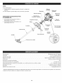
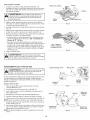
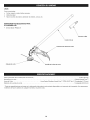
APPLiCATiONS
Asabrushcutter:
• Cutting
weedsandlightbrushupto1/2inchindiameter
Otheroptional
accessories
maybeusedwiththisunit.
Spark Plug
Choke Lever
Throttle Lock-Out
Starter
Rope Grip
ASSEMBLY
•
TOOLS
REQUIRED:
Medium flat-head screwdriver
Torx® screwdriver
Large flat-head screwdriver
screwdriver
On/Off Switch
or T-20
Filter
Cover
Support Fitting
or T-25 Torx
Handle
Coupler
Shaft Grip
Fuel Cap
Throttle
Shaft Housing
Control
Primer Bulb
Barrier
Bar
\
Blade Shield
Engine Type ........................................................................................
Displacement .......................................................................................
Spark Plug Gap ....................................................................................
Spark Plug ..........................................................................
Lubrication ...........................................................................................
Fuel/Oil Ratio ..................................................................................................
Fuel Tank Capacity ......................................................................................
Approximate Unit Weight (No fuel, with blade, blade shield and handle) ......................................
Cutting Mechanism ................................................................................
Shoulder Strap ......................................................................................
Cutting Path Diameter ...................................................................................
* All specifications are based on the latest product information
time without notice.
Champion®
Air-Cooled, 2-Cycle
27 cc (1.64 cu. in.)
0.025 in. (0.635 mm)
RDJ7J or equivalent plug
Fuel/Oil Mixture
40:1
14 oz. (414 ml)
11 - 13 Ibs. (5 - 5.9 kg)
4-Tooth Cutting Blade
Single Quick-Snap
8 in. (20.32 cm)
available at the time of printing. We reserve the right to make changes at any
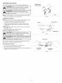
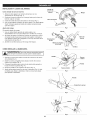
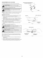
iNSTALLiNG AND ADJUSTING
Installing the Barrier
THE HANDLE
Barrier Bar
Screw_
Bar
.
Handle
1. Align the two pegs on the barrier bar with the two holes in the
handle (Fig. 1).
2. Press the barrier bar into the handle until the barrier bar snaps
into place.
3. Insert the barrier bar screw into the handle (Fig. 1).
4. Use a medium flat-head screwdriver or a T-20 Torx® screwdriver
to tighten the barrier bar screw until the barrier bar is secure.
Barrier
,
\0-_
"
,f
Adjusting the Handle
Fig. 1
If the handle requires adjustment:
1. Use a large flat-head screwdriver or a T-25 Torx screwdriver to
loosen the 4 screws in the handle.
2. While holding the unit in the operating position, move the handle
to the location that provides the best grip. Place it a minimum of
6 inches (15.24 cm) from the end of the shaft grip (Fig. 2).
3. Tighten the screws until the handle is secure.
Barrier
Shaft Grip
Screws
INSTALLING THE SHOULDER STRAP
To avoid serious
Fig. 2
i
i
_WARNING:
personal
injury, always use J
the shoulder strap when operating
the brushcutter.
1.
2.
Push the strap up through the center slot in the buckle (Fig. 3).
Bend the strap over and push it down through the lower slot in
the buckle (Fig. 3).
3. Put the shoulder strap over the operator's head and onto the left
shoulder (Fig. 14).
4. Snap the clip onto the support fitting (Fig. 4).
5. Adjust the shoulder strap to fit the operator (Fig. 5). Pull the
buckle up to loosen the shoulder strap. Pull the strap down to
tighten the shoulder strap.
Buckle
Strap '
Center
Slot
/
Clip
Lower Slot
Fig. 3
Clip
Support
Fig. 4
\
Buckle
Stra
Fig. 5
Fitting
Bar
OPERATING
THE COUPLER
90° Edging Hole
(Trimmer Only)
The coupler enables the use of various optional attachments.
_
WARNING:
using any
attachment,
Follow all safetyBefore
information
contained
within. read and
J
_
damage to the unit, shut the unit off before removing or
WARNING:
To avoid serious personal injury and
installing an attachment.
j
understand the manual that came with the attachment.
Knob
NOTE: To make installing or removing the attachment
the unit on the ground or on a work bench.
installing
easier, place
Fig. 6
the Attachment
NOTE: Remove the protective cap and gray spacer from the upper
and lower shafts prior to assembling the attachment.
1. Turn the knob counterclockwise
to loosen (Fig. 6).
Release Button
Coupler
2. While firmly holding the attachment, push it straight into the
coupler until the release button snaps firmly into the primary
hole (Fig. 8).
NOTE: Aligning the release button with the guide recess will help
installation (Fig. 7).
3. Turn the knob clockwise to tighten (Fig. 6).
NOTE: Do not tighten the nut (Fig. 7).
IAIc,o ,o°; e,o eo
I e ati theun,t,
release button is fully snapped into the primary hole (Fig. 8)
and the knob (Fig. 6) is securely tightened.
_
the primary hole only. Using the wrong hole could lead to
CAUTION:
release button
should be snapped into
personal injuryThe
or damage
to the unit.
For decorative edging with a string trimmer attachment,
release button into the 90 ° edging hole (Fig. 6).
Fig. 7
1
i
Primary Hole
lock the
Removing the Attachment
1. Turn the knob counterclockwise
to loosen (Fig. 6).
2. Press and hold the release button (Fig. 7).
3. While firmly holding the upper shaft housing, pull the attachment
straight out of the coupler (Fig. 8).
Upper Shaft
Housing
Lower Shaft
Housing
Fig. 8
FUELING THE UNiT
OiL AND FUEL MiXiNG iNSTRUCTiONS
The use of old and/or improperly mixed fuel is the most common cause
of performance problems. Use only fresh, clean unleaded gasoline.
Follow the instructions carefully for the proper gasoline/oil mixture.
Definition of Blended
WARNING:
Gasoline is extremely flammable. Ignited
vapors may explode. Always stop the engine and allow it
to cool before filling the fuel tank. Do not smoke while
filling the tank. Keep sparks and open flames at a distance
from the area.
Fuels
Today's fuels are often a blend of gasoline and oxygenates such as
ethanol, methanol or MTBE (ether). Alcohol-blended fuel absorbs
water. As little as 1% water in the fuel can make fuel and oil
separate, forming acids when stored. ALWAYS use fresh fuel (less
than 30 days old).
NOTE: Dispose of old fuel according to federal, state and local
regulations.
Using Blended
WARNING:
Remove the fuel cap slowly to avoid injury
from fuel spray. Never operate the unit without the fuel cap
securely in place.
WARNING:
Add fuel in a clean, well ventilated outdoor
area. Wipe up any spilled fuel immediately. Avoid creating
a source of ignition for spilled fuel. Do not start the engine
until fuel vapors dissipate.
Fuels
If using a blended fuel:
• Always use the fresh fuel mix explained in your operator's manual
Use the fuel additive STA-BIL® or an equivalent
Always agitate the fuel mix before fueling the unit
Drain the tank and run the engine dry before storing the unit
1. Position the unit with the fuel cap facing up.
2. Remove the fuel cap.
3. Place the fuel container spout into the fill hole on the fuel tank
and fill the tank.
NOTE: Do not overfill the tank.
I
J
has been proven that fuel containing greater than 10%
_WARNING:
DOdamage
NOT USE
FUEL
THIS
It
|
ethanol will likely
this E85
engine
andINvoid
theUNIT.
warranty.
Using Fuel Additives
The bottle of 2-cycle oil provided with this unit contains a fuel
additive to help inhibit corrosion and minimize gum deposits.
Always use the brand of 2-cycle oil that came with this unit. If this is
unavailable, use a 2-cycle oil designed for air-cooled engines and
mix it with a fuel additive, such as STA-BIL Fuel Stabilizer or an
equivalent. Add 0.8 oz. (23 ml) of fuel additive per gallon of fuel,
according to the instructions on the container. NEVER add fuel
additives directly to the unit's fuel tank.
Mixing the Fuel
NOTE: This unit comes with a 3.2 oz. bottle of 2-cycle oil. To obtain
the correct fuel mixture described below, pour the entire bottle
into one gallon of unleaded gasoline.
CAUTION:
For proper engine operation and maximum
reliability, pay strict attention to the gasoline and oil mixing
instructions on the 2-cycle oil bottle. Using improperly
mixed fuel can severely damage the engine.
Thoroughly mix the proper ratio of unleaded gasoline with 2-cycle
engine oil. Do not mix them directly in the unit's fuel tank. Use a
separate fuel can. Use a 40:1 gasoline/oil ratio. See the table below
for specific gasoline and oil mixing ratios.
Unleaded gasoline
2=cycle oil
1 gallon U.S.
(3.8 liters}
3.2 fL oz.
1 liter
25 rnl
(95 ml)
MIXING RATIO = 40:1
9
4.
5.
6.
Wipe up any fuel that may have spilled.
Reinstall the fuel cap.
Move the unit at least 30 ft. (9.1 m) from the fuel container and
the fueling site before starting the engine.
!
outdoor area. Carbon monoxide exhaust fumes can be
I_lib
[__J
I WARNING:
lethal in a confined
Operate
area.this unit only in a well-ventilated
J
serious injury, the operator and the unit must be in a stable
ARNING:
starting
position
when Avoid
pulling accidentally
the starter rope
(Fig.the
12).unit. To avoid I
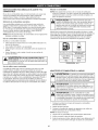
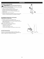
STARTING
INSTRUCTIONS
1. Mix gasoline with oil. Refer to Oil and Fuel Mixing Instructions.
2. Fill the fuel tank. Refer to Fueling the Unit.
NOTE: There is no need to turn the unit on. The On/Off switch is in
the ON (I) position at all times (Fig. 9).
3. Slowly press and release the primer bulb 10 times (Fig. 10). If
fuel cannot be seen in the primer bulb, press and release the
primer bulb until fuel is visible.
4. Flip the choke lever clockwise until it clicks (Fig. 11).
5. Crouch in the starting position (Fig. 12).
6.
Fig. 9
DO NOT squeeze the throttle control (Fig. 9). Pull the starter rope
with a controlled and steady motion until the unit starts (Fig. 12).
S
Primer Bulb
NOTE: This unit uses the INCREDI-PULL TM starting system, which
significantly reduces the effort required to start the engine.
7. Idle the engine for 5 to 10 seconds. If the unit stops during this
time, squeeze and hold the throttle control and throttle lock-out.
Then pull the starter rope in a controlled and steady motion until
the unit starts.
8.
Squeeze and hold the throttle control and throttle lock-out. Allow
the engine to warm up for 30 to 60 seconds.
NOTE: The engine is properly warmed up when it accelerates
without hesitation.
Fig. 10
iF... the engine does not start, begin the starting procedure with
step 3.
IF... the unit is hot and fails to start within 3 pulls of the starter rope,
squeeze and hold the throttle control and throttle lock-out. Then
pull the starter rope with a controlled and steady motion until the
unit starts.
STOPPING
1.
2.
Choke Lever
iNSTRUCTiONS
Release the throttle control and allow the engine to idle.
Press and hold the On/Off switch in the OFF (O) position until
the engine comes to a complete stop (Fig. 9).
Fig. 11
Starter Rope Grip
Throttle
Starting
Position
Control
Fig. 12
10
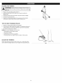
Thisunitcanbestartedwithanoptional
SpeedStart
TM accessory
(items sold separately). Please refer to the Speed Start TM accessory
operator's manual for the proper use of this feature.
Please contact your local Craftsman retailer, call 1=800=469=4663 or
visit www.craftsman.com
for more information.
item No.
316.85951
316.85951
316.85953
Description
..............................
..................................
.............................
Plugqn Power Start
Power Bit Start
Cordless Power Start
STARTING iNSTRUCTiONS
1.
Mix gasoline with oil. Refer to Oil and Fuel Mixing Instructions.
2. Fill the fuel tank. Refer to Fueling the Unit.
NOTE: There is no need to turn the unit on. The On/Off switch is in
the ON (I) position at all times (Fig. 9).
3. Slowly press and release the primer bulb 10 times (Fig. 10). If
fuel cannot be seen in the primer bulb, press and release the
primer bulb until fuel is visible.
4. Flip the choke lever clockwise until it clicks (Fig. 11).
5. Crouch in the starting position (Fig. 12).
6. DO NOT squeeze the throttle control (Fig. 9). Insert the Speed
Start TM accessory into the Speed Start TM port (Fig. 13). Refer to
the Operation section of the Speed Start TM accessory operator's
manual.
7.
DO NOT squeeze the throttle control. Run the Speed Start TM
accessory in intervals no longer than 2 seconds each until the
unit starts.
8.
Idle the engine for 5 to 10 seconds. If the unit stops during this
time, squeeze and hold the throttle control and throttle lock-out.
Then run the Speed Start TM accessory in intervals no longer than
2 seconds each until the unit starts.
Speed Start
Port
Fig. 13
9. Remove the Speed Start TM accessory from the unit.
10. Squeeze and hold the throttle control and throttle lock-out. Allow
the engine to warm up for 30 to 60 seconds.
NOTE: The engine is properly warmed up when it accelerates
without hesitation.
iF... the engine does not start, begin the starting procedure with
step 3.
iF... the unit is hot and fails to start within 3 pulls of the starter rope,
squeeze and hold the throttle control and throttle lock-out. Then
run the Speed Start TM accessory in intervals no longer than 2
seconds each until the unit starts.
STOPPING
1.
2.
INSTRUCTIONS
Release the throttle control and allow the engine to idle.
Press and hold the On/Off switch in the OFF (O) position until
the engine comes to a complete stop (Fig. 9).
11
TM
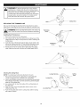
HOLDINGTHE
UNiT
body protection to reduce the risk of injury when operating
this unit.
•
Stand in the operating position (Fig. 14).
Hold the shaft grip with the right hand. Keep the right arm
slightly bent.
Hold the handle with the left hand. Keep the left arm straight.
Hold the unit at waist level.
Keep the cutting head parallel to the ground so that it easily
contacts the brush without the need for bending over.
Stand in a stable position with feet apart and firmly planted.
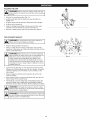
TiPS FOR BEST
_
Fig. 14
RESULTS
others, do not To
useavoid
the blade
as an
edger.
_JARNING:
serious
injury
to the operator or
o
Keep the blade parallel to the ground.
o
Always cut with the unit running at full speed. This provides
maximum cutting power and makes the blade less likely to bind,
stall or cause blade thrust.
1
WARNING:
Blade thrust can occur when the spinning
blade contacts an object that it does not immediately cut.
Blade thrust can be violent enough to cause the unit
and/or operator to be propelled in any direction and
possibly lose control of the unit. Blade thrust can occur
without warning if the blade snags, stalls or binds. This is
more likely to occur in areas where it is difficult to see the
material being cut.
Fig. 15
Cut from left to right (Fig. 15). This improves the unit's cutting
efficiency and throws debris away from the operator. To prevent
material wrapping around the blade, avoid cut debris on the
return swing.
Always release the throttle control and allow the unit to idle
when not cutting.
When finished, always unsnap the shoulder strap from the unit
before taking off the shoulder strap.
The blade has a second cutting edge. If the blade becomes dull,
remove the blade, turn it upside down and reinstall the blade. If
both sides are dull, replace the blade. Refer to Replacing the Blade.
!
_
after the unit is turned off. To avoid serious personal injury,
WARNING:
blade blade.
will continue to spin for a while
do not touch aThe
coasting
1
|
personal injury, always
the unit off before removing debris from the unit. Allow the I
_WARNING:
avoid
seriousstop.
turn |I
bade to come To
to a
compete
J
B
12
WARNING:
To prevent serious injury, never perform
maintenance or repairs while the unit is running. Always
allow the unit to cool before servicing or repairing the unit.
Disconnect the spark plug wire to prevent the unit from
starting accidentally.
MAINTENANCE
SCHEDULE
Shaft Bushing
Perform these required maintenance procedures at the frequency
stated in the table. These procedures should also be a part of any
seasonal tune-up.
NOTE: Some maintenance procedures may require special tools or
skills, if unsure about these procedures, take the unit to a Sears
or other qualified service dealer. Call 1-800-469-4663 for more
information.
MAINTENANCE
Every 10 hours
Clean and re-oil the air filter. Refer to
Maintaining the Air Filter.
Every 25 hours
Check the spark plug condition and gap. Refer
to Maintaining the Spark Plug.
Output Shaft
Locking Rod Slot
NOTE: Maintenance, replacement, or repair of the emission control
devices and system may be performed by a Sears or other qualified
service dealer. Call 1-800-469-4663 for more information.
NOTE: Please read the California/EPA statement that came with the
unit for a complete listing of terms and coverage for the
emissions control devices, such as the spark arrestor, muffler,
carburetor, etc.
FREQUENCY
Hole
Locking Rod
Fig. 16
REQUIRED
Nut
Locking Rod
Clockwise
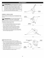
ft_us,n
REPLACING THE BLADE
g
_'_
/_
Fig. 17
WARNING:
To avoid
serious
personal injury, always
wear gloves when
handling
the blade.
WARNING:
Dothe
notblade
sharpen
thebreak
blade.
blade can cause
tip to
off Sharpening
while in use.the
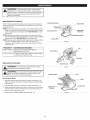
Removing
Nut
Blade Retainer
This can result in severe personal injury.
the Blade
Blade
1. Align the shaft bushing hole with the locking rod slot (Fig. 16).
Insert the locking rod into the locking rod slot and shaft bushing
hole (Fig. 16).
2. Hold the locking rod firmly against the shaft housing (Fig. 17).
3. While holding the locking rod in place, loosen the nut by turning it
clockwise with a 5/8 inch closed-end or socket wrench (Fig. 17).
4. Remove the locking rod (Fig. 18).
5. Remove the nut, blade retainer and blade (Fig. 18).
Locking Rod
Output Shaft
Bushing
Fig. 18
13
Installing
theBlade
1. Putthebladeontheoutputshaftbushing
(Fig.18).Makesure
thebladeiscentered
onthepilotstep(Fig.19).Theblade
shouldsitflatagainst
theoutputshaftbushing.
and the blade may fly off, possibly causing serious
ARNING"
personal
injury. If the blade is off-center, the unit will vibrate
_
Blade
J
Pilot Step
2. Align the shaft bushing hole with the locking rod slot (Fig. 16).
Insert the locking rod into the locking rod slot and shaft bushing
hole (Fig. 16).
3. Hold the locking rod firmly against the shaft housing (Fig. 17).
4. While holding the locking rod in place, put the blade retainer and
nut on the output shaft (Fig. 19).
5. While holding the locking rod in place, tighten the nut by turning
it counterclockwise:
Fig. 19
• If you are using a torque wrench and an 5/8 inch socket,
tighten the nut to: 325 - 335 inolb, 27 - 28 ft._lb, 37 - 38 N_rn.
Without a torque wrench, use a 5/8 inch closed-end or socket
wrench. Turn the nut until the blade retainer is snug against
the shaft bushing. Make sure the blade is installed correctly,
then rotate the nut an additional 1/4 to 1/2 turn
counterclockwise
(Fig. 20).
6. Remove the locking rod.
1/4 - 1/2 Turn
Counterclockwise
I
to the unit, do not start or operate the unit with the locking
[_J
WARNING:
To the
avoid
serious
injury or damage
rod inserted into
locking
rod personal
slot.
MAINTAINING
Fig. 20
THE AIR FILTER
the engine and allow it to cool before cleaning or maintaining
WARNING;
the unit.
To avoid serious personal injury, always stop
_
1
I
Air Filter Cover
Air Filter
J
Failure to maintain the air filter can result in poor performance or can
cause permanent damage to the engine. Engine failure due to
improper air filter maintenance is not covered by the product warranty.
Cleaning
1.
Air Filter
the Air Filter
Cover
Housing
Screw
Open the air filter cover by unscrewing the cover screw (Fig. 21).
Fig. 21
2. Remove the air filter from inside the air filter housing (Fig. 21).
3. Wash the air filter in detergent and water. Rinse the air filter
thoroughly and allow it to dry.
4. Lightly coat the air filter with clean SAE 30 oil.
5. Squeeze the air filter to spread and remove excess oil.
6. Reinstall the air filter inside the air filter housing (Fig. 22).
NOTE: Operating the unit without the air filter and air filter cover will
VOiD the warranty.
7. insert the hooks on the air filter housing into the slots on the air
filter cover (Fig. 22).
8. Swing the air filter cover to the right and align the cover screw
with the cover screw hole (Fig. 22). Tighten the cover screw to
secure the air filter cover.
Cover
Slots
Hooks
Air Filter
Cover
NOTE: Do not over tighten as this may strip the screw.
Air Filter
Housing
Fig. 22
14
Screw Hole
ADJUSTING THE iDLE SPEED
[die Speed Screw
adjustments. Wear protective clothing and observe all
The cutting head may spin during idle speed[
safety nstruct ons to prevent serous persona njury,
j
WARNIN6:
NOTE: Careless adjustments can seriously damage the unit. A Sears or
other qualified service dealer should make carburetor adjustments.
If, after checking the fuel and cleaning the air filter, the engine still
will not idle, adjust the idle speed screw as follows:
1. Start the engine. Refer to Starting and Stopping.
i
2.
Release the throttle control and let the engine idle. If the engine
stops, use a small Phillips screwdriver to turn the idle speed screw
clockwise, 1/8 of a turn at a time (as needed) until the engine idles
smoothly (Fig. 23).
3. If the engine is idling too quickly, turn the idle speed screw
counterclockwise, 1/8 of a turn at a time (as needed) to reduce the
idle speed (Fig. 23).
Checking the fuel, cleaning the air filter, and adjusting the idle speed
should solve most engine problems. If not, and any of the following
conditions are true, take the unit to a Sears or other qualified service
dealer:
•
Fig. 23
the engine will not idle
the engine hesitates or stalls on acceleration
there is a loss of engine power
MAINTAINING
THE SPARK PLUG
1. Stop the engine and allow it to cool. Grasp the spark plug boot
firmly and pull it from the spark plug.
2. Clean around the spark plug. Remove the spark plug from the
cylinder head with a 5/8-inch socket, turning counterclockwise.
!
electrodes. GritDo
in not
the sand
engine
could
damage
the cylinder.
_WARN[NG;
blast,
scrape
or clean
spark plug[
J
3.
inspect the spark plug. if the spark plug is cracked, fouled or
dirty, replace it with a replacement part #753=06193, a
Champion RDJ7J or an equivalent spark plug.
4. Use a feeler gauge to set the air gap at 0.025 in. (0.635 ram)
(Fig. 24).
5. install the spark plug in the cylinder head. Tighten the spark plug
with a 5/8-inch socket, turning it clockwise until snug.
NOTE: if using a torque wrench, torque to:
110=120 in.olb. (12.3=13.5 N_m). Do not over tighten.
6. Reattach the spark plug boot.
0.025 in.
{0.635 rnrn}
t
Fig. 24
15
CLEANING
STORAGE
•
_
the engine and allow it to cool before cleaning or maintaining
To avoid serious personal injury, always stop
WARNING"
the unit.
J
Use a small brush to clean the outside of the unit. Do not use strong
detergents. Household cleaners that contain aromatic oils such as
pine and lemon, and solvents such as kerosene, can damage plastic.
Wipe off any moisture with a soft cloth.
Never store a fueled unit where fumes may reach an open flame
or spark.
Allow the engine to cool before storing.
Lock up the unit to prevent unauthorized use or damage.
Store the unit in a dry, well-ventilated area.
Store the unit out of the reach of children.
Short-term
Storage (1=2 weeks)
1. Store the unit in a horizontal position. If this is not possible, store
the unit vertically with the engine at the top.
Long-term Storage
1. Remove the fuel cap, tip the unit and drain the fuel into an
approved container. Reinstall the fuel cap.
2. Start the engine and allow it to run until it stalls. This ensures
that all fuel has been drained from the carburetor.
3. Allow the engine to cool. Remove the spark plug and put 5 drops
of any high quality motor oil or 2-cycle oil into the cylinder. Pull the
starter rope slowly to distribute the oil. Reinstall the spark plug.
4. Thoroughly clean the unit and inspect it for any loose or
damaged parts. Repair or replace damaged parts and tighten
loose screws, nuts or bolts.
Preparing the Unit for Use after Long=term
Storage
1. Remove the spark plug and drain all of the oil from the cylinder.
NOTE: Do not use fuel that has been stored for more than 30 days.
Dispose of old fuel according to federal, state and local regulations.
16
PROBLEM
SOLUTION
The primer bulb was not pressed enough
Press the primer bulb 10 times or until fuel is visible
The fuel is old (over 30 days) and/or improperly mixed
Drain the fuel tank and add fresh, properly mixed fuel
The fuel is old (over 30 days) and/or improperly mixed
Drain the fuel tank and add fresh, properly mixed fuel
The fuel is old (over 30 days) and/or improperly mixed
Drain the fuel tank and add fresh, properly mixed fuel
The air filter is dirty
Clean or replace the air filter
The fuel is old (over 30 days) and/or improperly mixed
Drain the fuel tank and add fresh, properly mixed fuel
The spark plug is fouled
Replace the spark plug
17
Congratulations on making a smart purchase. Your new Craftsman@ product is designed and manufactured for years of dependable
operation. But like all products, it may require repair from time to time. That's when having a Repair Protection Agreement can save you
money and aggravation.
Here's what the Repair Protection Agreement*
includes:
[]
Expert service
[]
[]
[]
Unlimited service and no charge for parts and labor on all covered repairs
Product replacement up to $1500 if your covered product can't be fixed
Discount of 25% from regular price of service and related installed parts not covered by the agreement; also, 25% off regular price of
preventive maintenance check
Fast help by phone - we call it Rapid Resolution - phone support from a Sears representative. Think of us as a "talking owner's manual."
[]
by our 10,000 professional repair specialists
Once you purchase the Repair Protection Agreement, a simple phone call is all that it takes for you to schedule service. You can call anytime
day or night, or schedule a service appointment online.
The Repair Protection Agreement is a risk-free purchase. If you cancel for any reason during the product warranty period, we will provide a
full refund. Or, a prorated refund anytime after the product warranty period expires. Purchase your Repair Protection Agreement today!
Some limitations and exclusions apply. For prices and additional information in the U.S.A. call 1-800-827-6655.
*Coverage in Canada varies on some items. For full details call Sears Canada at 1-800-361-6665.
Sears installation Service
For Sears professional instaflation of home appliances,
Canada call 1-800-4-MY-HOME.
garage door openers, water heaters, and other major home items, in the U.S.A. or
18
Manual
del Operador
M
Motor
de 2 tiernpos
Con Posibilidad de Arranque El_ctrico
BUSHWACKER_ DESBROZADORA
Modelo No. 316.725860
U_F_VABLE
$7_A_T_G
EA $ E _
o SEGURIDAD
o ENSAMBLAJE
o OPERACION
PRECAUCION: Antes de utilizar, este
producto lea este manual y siga todas
las reglas de seguridad
e instrucciones
de operaci6n.
Sears Brands Management
Corporation,
Visite nuestro
769-08606 00
o MANTENIMIENTO
LISTA DE PIEZAS
Hoffman
Estates, IL 60179 U.S.A.
sitio web: www.craftsman.com
11/12
TABLA DE CONTENIDO
Seguridad ...........................................
Garantia .............................................
Conozca su unidad ....................................
20
23
24
Especificaciones
......................................
Ensamblaje ..........................................
Aceite y combustible ...................................
Arranque y parada .....................................
Operaci6n ...........................................
Mantenimiento ........................................
24
25
27
28
30
31
Limpieza y almacenamiento
.............................
34
Accesorio Speed Start TM ................................
34
Localizaci6n y soluci6n de problemas .....................
35
Convenio de protecci6n de reparaci6n .....................
36
Lista de piezas .......................................
38
NQmeros de servicio .........................
Contraportada
Toda la informaci6n, las ilustraciones y especificaciones que contiene
este manual se basan en la informaci6n mas reciente del producto,
existente en el momento de la impresi6n. Nos reservamos el derecho
de hacer cambios en cualquier momento, sin previo aviso.
© Seam Brands, LLC
NOTA SOBRE EL PARACHISPAS
El prop6sito de los simbolos de seguridad es Ilamar la atenci6n
sobre posibles peligros. Los simbolos de seguridad y sus
explicaciones merecen toda su atenci6n y comprensi6n. Las
advertencias de seguridad no eliminan de por si ningQn peligro.
Las instrucciones o advertencias que dan no sustituyen las
medidas adecuadas de prevenci6n de accidentes.
SJMBOLO
NOTA: Para usuarios de la Zona Forestal de EE. UU., y los
estados de California, Maine, Oreg6n y Washington. Todas las
zonas forestales de EE.UU., asi como los estados de California
(C6digos de Recursos PQblicos 4442 y 4443), Oreg6n y Washington
exigen, por ley, que determinados motores de combusti6n interna
operados en matorrales boscosos y/o zonas cubiertas de hierba,
esten equipados con un parachispas y se mantengan en buen estado
de funcionamiento, o que el motor sea construido, equipado y
mantenido con vista a la prevenci6n de incendios. Compruebe con
las autoridades de su estado o Iocalidad las reglamentaciones
relacionadas con estos requisitos. Si no cumple estos requisitos
podria estar sujeto a responsabilidad civil o multa. Esta unidad viene
equipada de f_brica con un parachispas. El reemplazo requiere la
pieza No. 753-06418 del conjunto del silenciador, instalada en un
Centro de Piezas y Servicio de Reparaciones de Sears.
SlGNIFICADO
PEUGRO:
Indica un peligro EXTREMO.
El no obedecer una sehal de seguridad de PEUGRO
TRAERA COMO CONSECUENClA que usted u otras
personas puedan sufrir lesiones graves o la muerte.
ADVERTENCIA:
Indica un peligro GRAVE.
El no obedecer una sehal de ADVERTENClA de seguridad
PUEDE conducir a que usted u otras personas sufran
graves lesiones.
PRECAUCl0N:
PROPOSlCION
Los gases de escape, algunos de sus
componentes y determinados productos terminados
contienen o emiten productos quimicos de los que el estado
de California tiene conocimiento provocan cancer,
malformaciones congenitas u otros da_os al sistema
reproductor. Lavese las manos despues de manipularlos.
Indica un peligro MODERADO.
El no obedecer una sehal de PRECAUClON de seguridad
PUEDE conducir a dahos a la propiedad o a que usted u
otras personas se lesionen.
NOTA" Indica informaci6n o instrucciones de vital importancia
la operaci6n o el mantenimiento del equipo.
65 DEL ESTADO DE CALiFORNiA
ADVERTENClA:
para
Lea el manual del operador y siga todas las advertencias e
instrucciones de seguridad. No hacerlo puede ocasionar
lesiones graves al operador y/o alas personas presentes.
2O
• INSTRUCCIONES
LEA TODAS LAS INSTRUCCIONES
LA UNIDAD
_
•
DE SEGURIDAD
ANTES DE OPERAR
Utilice anteojos o antiparras de seguridad que cumplan con las
normas ANSI Z87.1 vigentes y que tengan la identificaci6n
correspondiente. Utilice una protecci6n auditiva al operar esta
unidad. Utilice una mascara facial o para polvos si la maquina
levanta polvo durante su funcionamiento.
Use pantalones largos y gruesos, botas, guantes y camisa de
mangas largas. No use ropa holgada, alhajas, pantalones
cortos, sandalias ni ande descalzo. Asegure su cabello pot
encima del nivel de los hombros.
Lea detenidamente las instrucciones. Familiaricese con los
controles y el uso adecuado de la unidad.
No opere esta unidad siesta cansado, enfermo o bajo los
efectos del alcohol, drogas o medicamentos.
El protector de la cuchilla debe estar siempre en su sitio mientras
se opere la unidad.
Esta unidad tiene un embrague. La cuchilla permanece estacionaria
cuando el motor trabaja en vacio. De no hacerlo, Ileve la unidad a
Sears o a otro distribuidor de servicio calificado para su ajuste.
La cuchilla puede girar durante los ajustes de marcha en vacio.
Use ropa de protecci6n y observe todas las instrucciones de
seguridad para evitar lesiones personales graves.
Ajuste el mango para facilitar el mejor agarre.
Compruebe que el accesorio no este en contacto con nada
antes de poner en marcha la unidad.
Use la unidad Onicamente a la luz del dia o con buena luz artificial.
deben
Se deben instalar correctamente todos los protectores y
accesorios de seguridad antes de operar la unidad.
Inspeccione la unidad antes de usarla. Reemplace las piezas
dar_adas. Compruebe si hay perdidas de combustible.
Compruebe que todas las sujeciones esten en su lugar y bien
ajustadas. Reemplace las piezas que esten agrietadas,
astilladas o dar_adas de cualquier manera. No utilice la unidad si
hay piezas sueltas o dar_adas.
Inspeccione el Area con atenci6n antes de arrancar la unidad.
Extraiga las rocas, los vidrios rotos, los clavos, los cables,
cordeles y demas objetos que podrian ser arrojados o enredarse
en la unidad.
Evite los arranques accidentales. P6ngase en la posici6n de
arranque siempre que tire de la cuerda. El operador y la unidad
deben estar en una posici6n estable durante el arranque.
Consulte la secci6n Arranque y Parada.
Use la herramienta correcta. Use esta herramienta solamente
con el prop6sito previsto.
Sostenga siempre la unidad con ambas manos al operarla.
Agarre firmemente ambos mangos o empu_aduras.
No intente alcanzar demasiado lejos. Mantenga siempre una
posici6n y equilibrio adecuados. Tenga mucho cuidado cuando
este trabajando en pendientes pronunciadas o inclinadas.
Mantenga las manos, la cara y los pies lejos de todas las partes
m6viles. No toque o trate de detener las piezas m6viles.
No toque el motor, el bastidor del engranaje ni el silenciador.
Estas partes se ponen extremadamente calientes durante la
operaci6n y aOn despues de apagada la unidad.
No opere la unidad a una velocidad mayor a la necesaria para la
tarea. No haga funcionar la unidad a alta velocidad cuando no esta
en uso.
Tenga en cuenta el riesgo de lesiones a la cabeza, las manos y
los pies.
Despeje la zona de ni_os, observadores y mascotas;
mantengalos fuera de un radio de 50 pies (15 m), como minimo.
Incluso a esa distancia, sigue el riesgo de ser alcanzados por
los objetos arrojados por el aire. Sugierales a los observadores
que usen protecci6n ocular. Si alguien se le aproxima, detenga
la unidad de inmediato.
Apriete el control del regulador y compruebe que regresa
automaticamente a la posici6n de marcha en vacio. Haga todos
los ajustes o reparaciones antes de usar la unidad.
ADVERTENCIAS
GASOLINA
DE SEGURIDAD
PARA UNIDADES
•
AL OPERAR LA UNIDAD
las normas de seguridad. Lea estas instrucciones antes de
operar la unidad a fin de garantizar la seguridad del
I
operador
y de cualquier
otra la
persona
Guardetodas I
DVERTENCIA:
AI usar
unidad presente.
deben seguirse
estas instrucciones para poder usarlas mas adelante,
j
Los nitros no deben operar la unidad. Los adolescentes
estar acompa_ados y supervisados pot un adulto.
IMPORTANTES
DE
y, de prenderse, sus vapores pueden hacer expos 6n.
|
ADVERTENCIA:
La gasolina es sumamente inflamable
Tome las siguientes precauciones:
J
Almacene el combustible solo en los recipientes diser_ados y
aprobados especificamente para estos materiales.
Pare siempre el motor y deje que se enfrie antes de Ilenar el tanque.
Nunca quite la tapa del tanque de combustible ni eche combustible
cuando el motor este caliente. Antes de Ilenar el tanque, siempre
afloje la tapa lentamente para disipar la presi6n del mismo.
Mezcle o eche siempre el combustible en un Area exterior bien
ventilada y limpia, donde no haya chispas ni llamas. NO fume.
No opere nunca la unidad si la tapa del combustible no esta
bien asegurada en su lugar.
Evite el peligro de incendio debido a combustible derramado.
Limpie de inmediato todo combustible derramado de la unidad
antes de encenderla. Antes de arrancar el motor, aleje la unidad
a una distancia de 30 pies (9.1 m) como minimo del lugar de
abasto de combustible. NO fume.
No exija demasiado a la unidad. Si se usa a la velocidad para la
que fue dise_ada, realizara un trabajo mas eficiente y seguro.
Detenga siempre la unidad cuando la operaci6n este demorada o
cuando camine de un lugar a otto.
Si golpea un objeto extra_o o si este se engancha en la unidad,
detengala de inmediato y controle si se produjeron da_os. No
utilice la unidad hasta haber reparado el dar_o. No utilice la
unidad si hay piezas sueltas o dar_adas.
Apague el motor y desconecte la bujia para darle mantenimiento
o hacer reparaciones.
Utilice solamente las piezas de repuesto y accesorios del
fabricante original que se listan en la secci6n Lista de piezas de
este manual. El uso de cualquier pieza o accesorio no
autorizado podria causar lesiones graves al usuario o dar_os a la
unidad y anular la garantia.
Mantenga limpia la unidad. Quite con cuidado cualquier resto de
vegetaci6n u otros residuos que puedan bloquear las piezas
m6viles.
Para evitar el peligro de incendio, reemplace el silenciador y
parachispas defectuosos. Mantenga el motor y el silenciador sin
hierbas, hojas, grasa excesiva y sin acumulaci6n de carb6n.
Si la unidad comienza a vibrar anormalmente, det6ngala de
inmediato. Inspeccione la unidad para encontrar la causa de la
vibraci6n. Generalmente, la vibraci6n es un indicador de problemas.
No arranque ni use nunca la unidad dentro de una habitaci6n o
edificio cerrados. Inhalar los gases de escape puede ser fatal.
Opere esta unidad solamente en un Area exterior bien ventilada.
21
• Usesiempre
elarnes
paraelhombro
cuando
opere
ladesbrozadora.OTRAS ADVERTENCIAS DE SEGURIDAD
Mantenga
elmango
entreeloperador
ylacuchilla
decorteen
Todas las tareas de reparaci6n, con excepci6n de los
todomomento.
procedimientos de mantenimiento que se describen en este
NUNCA
cortecuando
lacuchilla
estea30pulgadas
(76cm)o
manual, deben ser realizados por un distribuidor de Sears u otro
m_,s
porencima
delniveldelatierra.
distribuidor de servicio autorizado.
Sepuedeproducir
unempuje
delacuchilla
cuando
entraen
Antes de inspeccionar, limp!at, guardar o transportar la unidad, o
contacto
conunobjetosinoIocortadeinmediato.
Elempuje
de
de hacer tareas de reparaci6n o mantenimiento o reemplazar
lacuchilla
puede
serIosuficientemente
violento
comopara
alguna de sus piezas:
mover
launidad
y/oaloperador
encualquier
direcci6n
1. Detenga la unidad.
ocasionando,
posiblemente,
perdida
delcontrol.
Elempuje
dela
2. AsegQrese de que se hayan detenido todas las piezas m6viles.
cuchilla
puede
producirse
sinavisosilacuchilla
sedesbasta,
se
3. Deje que la unidad se enfrie.
atasca
osedobla.Estoesm_,s
probable
queenAreas
enlas
queesdificilverelmaterial
queseesta,
cortando.
4. Desconecte el cable de la bujia.
Nocortenadaconungrosor
mayorde1/2pulgada
o podria
Sujete la unidad durante el transporte.
ocurrirunretroceso
violento.
Nunca almacene la unidad con combustible en el dep6sito, en el
Unacuchilla
girando
porinercia
puedecausar
lesiones
mientras
interior de una construcci6n donde las emanaciones puedan
continQa
girando
despues
dequesehaparado
elmotoroseha
alcanzar una llama abierta (luces piloto, etc.) o chispas
soltadoelcontrol
delregulador.
Mantenga
control
adecuado
(interruptores, motores electricos, etc.).
hastaquelacuchilla
hayadejado
degirarcompletamente.
Almacene la unidad en un lugar seco, asegurada o a una altura
Nooperelaunidad
conlacuchilla
doblada,
agrietada
odesafilada. que evite que se la use sin autorizaci6n o se la dafie. Mantenga
Deseche
lascuchillas
dobladas,
deformadas,
agrietadas
orotas.
la unidad lejos del alcance de los nifios.
Noafilelacuchilla.
Afilarlacuchilla
puede
hacerquelapuntade
Nunca rocie ni arroje chorros de agua ni de ningQn otro liquido a la
lacuchilla
serompa
mientras
seusa.Estopuedeprovocar
unidad. Mantenga las manijas secas, limp!as y sin residuos. Limpie
lesiones
personales
graves.
Reemplace
lacuchilla.
la unidad luego de cada uso. Consulte Limpieza y almacenamiento.
Nouselacuchilla
parabordesocomounrecortador
debordes;
Guarde estas instrucciones. ConsQItelas con frecuencia y Qselas
estopudiera
ocasionar
lesiones
personales
graves
austedoaotros.
para capacitar a otros usuarios. Si le presta esta unidad a otras
personas, tambien debe prestarles estas instrucciones.
GUARDE
• SJMBOLOS
INTERNACIONALES
ESTAS INSTRUCCIONES
Y DE SEGURIDAD
•
Este manual del operador describe simbolos y pictografias internacionales y de seguridad que posiblemente aparezcan en este producto.
Lea el manual del operador para informarse bien sobre la seguridad, ensamblaje, operaci6n, mantenimiento y reparaci6n.
SJMBOLO
SIGNIFICADO
SiMBOLO
SIGNIFICADO
COMBUSTIBLE
,_
Indic a peligro,
o PreCauci6n, DAD
Puede
SiMBOLO
DEadvertencia
ALERTA
DESEGUR
utiljzarse junto a otros sjmbo!os o pictografias.
o LEA EL MANUAL DEL OPERADOR
consuite ei tipo de aCeite adeCUado one! manua! dei
operador,
de segufidad_ No hacer!o puede 0casiona[ lesi0nes
graves al operador y/o a !as personas presentes;
ADVERTENCIA:
L0S 0bjet0s qUe son ariojados
_ o UTILICE PROTECCION OCULAR Y AUDITIVA
_--i!|
_= los!ones
por el aireoculareS
y los ruidos
fuertes cle
pueden
pr0v0car
graves
Y p@d!das
audjci6nl
Cuando
frescO, !impio y Sin
, ACEITE
ADVERTENCIA:
0perador y siga todas Lea
las el
advertenciaS
o los manuaieS
e instiUcCiones
de!
4t
SIN PLOMO
use siempre combustible
%
= NO USE COMBUSTIBLE
Probable que el Combustible con rn4s de ! 0%de
DVERTE"OJA:
Se ha
c0manu!ar4
Pr0bado!a qUe
etanol
dafie este motor,
Io que
garantia,
(_
I
opere esta unidad, uti!ice protecci6n ocular qu e
cump!a con !as no[mas ANSI Z87:1 vigentes y
protect0res auditJv0s, UtJlice una mascara clue cubra
todo el rostro si es necesario:
E85 EN ESTA UNIDAD
,' CONTROL
DEENCEND DOZAPAGADO
DEPARADA
ENCEND!DO _ ARRANQUE ! EUNC!ONAM!ENT Q
O
22
APAGADo o PAFIADA
mCONTROL DE ENCENDIDO/APAGADO
DE PARADA
SiMBOLO
SIGNIFICADO
SJMBOLO
, PERA DEL CEBADOR
' SUPERFICIE CALIENTE
ADVERTENCIA:
No toque un silenciador o
. cilindro calientes. Podria quemarse. Estas partes se
_I_ISSISI_;_I_I_
ponen extremadamente calientes durante la
operacl6n. Despu6s de apagada la unldad, se
mantendrb, n calientes durante un rato.
Optima ! 0 veces la pera del cebador, !entamente y ....
pot completo.
, LOS OBJETOS QUE SALEN DESPEDIDOS Y LA
CUCHILLA GIRATORIA PUEDEN OCASIONAR
LESIONES GRAVES
ADVERTENCIA:
' CORTADORAS DE MALEZAS - CAMBIE LA
CUCHILLA DESAFILADA
ADVERTENCIA:
No afile la cuchilla. Afilar la cuchilla
puede hacer que la punta de la cuchilla se rompa
. mientras se usa. Esto puede provocar lesiones
personales graves.
Los 0bjet0s pequefi0s pueden
set lanzados a gran velocidad y 0casionar lesiones.
Mant_ngaSe a!ejado de! rotor cuando est_ girandol
ADVERTENCIA:
Mantenga
tod0s i0S presentes,
, MANTENGA
LOS PRESENTES
especialmente ALEJADOS
a !os nifios A
Yan!males
d0m6sticos, a
una distancia de al menos 50 pies (15 m):
GARANTiA
TOTAL
POR DOS ANOS
SIGNIFICADO
' SEGURIDAD
DE LA CORTADORA DE MALEZAS
Los objetos que salen despedidos
y la cortadora giratoria pueden causar graves lesiones.
Mantenga a los espectadores, especialmente a los
nifios y animales dom6sticos a no menos de 15 m (50
pies) de distancia del Area de corte.
ADVERTENCIA:
CRAFTSMAN
Este producto se garantiza POR DOS ANOS a partir de la fecha de compra, contra cualquier defecto de materiales o mano de obra. Un
producto defectuoso se reparara sin costo alguno o se remplazara si no es posible repararlo.
GARANTJA LIMITADA ADICIONAL para los EJES DEL CORTADOR
A PARTIR DEL TERCER Y HASTA EL DECIMO ANO desde la fecha de compra, el cuerpo externo de metal de los ejes superior e inferior del
cortador estan garantizados contra defectos de materiales o fabricaci6n. Se proporcionara un cuerpo nuevo gratis con la presentaci6n del
comprobante de compra. Es su responsabilidad cubrir el costo de mano de obra de instalaci6n. Esta cobertura adicional no se aplica a los
componentes internos del eje de la cortadora.
Para conocer los detalles de la cobertura de garantia para la reparaci6n o reemplazo gratuitos, visite el sitio web: www.craftsman.com
Esta garantia cubre SOLAMENTE defectos de materiales o mano de obra. La cobertura de garantia NO incluye:
• Articulos de duraci6n limitada que pueden desgastarse en condiciones normales de uso durante el periodo de garantia, tales cuchillas,
bujias o filtros.
•
Los dafios al producto a consecuencia de intentos de modificaci6n o reparaci6n del usuario u ocasionados pot accesorios del producto.
Las reparaciones necesarias pot un accidente o pot no operar o mantener el producto de acuerdo con todas las instrucciones suministradas.
•
El mantenimiento preventivo ni las reparaciones necesarias debido a una mezcla incorrecta de combustible o a al uso de un combustible
viejo o contaminado.
Esta garantia se anula si el producto en algQn momento se utiliza para prestar servicios comerciales o se alquila a otra persona.
Esta garantia le confiere a usted derechos legales especificos y usted puede tener, ademas, otros derechos que difieren de un estado a otto.
Sears Brands Management
Corporation,
Para ordenar
o agendar
refacciones
Hoffman Estates, IL 60179
mantenimiento
para este producto, llame a 1-800-469-4663.
23
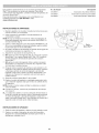
usos
Como desbrozadora:
Cortar malezas y arbustos peque_os de hasta V2pulgada de
diametro
Bujia de
encendido
Palanca del
obturador
Silenciador
Con esta unidad se pueden utilizar otros accesorios opcionales.
Traba del regulador
Agarre de la
cuerda de
Interruptor de
Encendido / Apagado
HERRAMIENTAS NECESARIAS PARA
EL ENSAMBLAJE:
Destornillador de hoja plana mediano o
destornillador Torx® 3--20
Enganche
Destornillador grande de hoja plana o un
destornillador Torx T-25
arranque
de apoyo
Tapa del
filtro de aire
Mango
EmpuSadura
del eje
Acoplador
Tapa del tanque
de combustible
Cuerpo
Control del
regulador
del eje
Pera del
cebador
Barra de barrera
Cuchilla
Protector
de la cuchilla
Tipo de motor .............................................................................
Cilindrada ....................................................................................
Abertura de la bujia ............................................................................
Bujia de encendido ..................................................................
Lubricaci6n ...............................................................................
Enfriado por aire, de 2 tiempos
27 cc (1.64 pulg. cObicas)
0.025 pulgadas (0.635 mm)
Bujia Champion® RDJ7J o equivalente
Mezcla de aceite/combustible
Proporci6n de aceite/combustible
..................................................................................
Capacidad del tanque de combustible ....................................................................
Peso aproximado de la unidad (No combustible, con cuchilla, protector de cuchilla y manija) ...................
Mecanismo de corte .........................................................................
Bandolera ...................................................................................
Diametro de la senda de corte .......................................................................
40:1
14 onzas (414 ml)
11 - 13 libras (5 - 5.9 kg)
Cuchilla de corte de 4 dientes
Broche individual a presi6n
8 pulgadas (20.32 cm)
* Todas las especificaciones se basan en la informaci6n del producto mas reciente disponible en el momento de la impresi6n. Nos reservamos
el derecho de hacer cambios en cualquier momento, sin previo aviso.
24
INSTALACION Y AJUSTE DEL MANGO
Tornillode
la barra de_
C6mo instalar la barra de barrera
._
__
Mango
1. Alinee los dos agujeros en la barra de barrera con los
dosorificios en el mango (Fig. 1).
2. Presione la barra de barrera en el mango hasta que la barra de
barrera caiga en su lugar.
3. Inserte el tornillo de la barra de barrera en el mango (Fig. 1).
4. Use un detornillador mediano de cabeza plana o un destornillador
Torx® -I--20 para apretar el tornillo de la barra de barrera hasta
que este segura.
Barra de barrera
"_-_
\\\k
Fig. 1
Ajuste del mango
Si necesita ajustar el mango:
1. Use un destornillador grande de cabeza plana o un
destornillador Torx T-25 para aflojar los 4 tornillos en el mango.
2. Sin dejar de sujetar la unidad en posici6n de operaci6n, mueva
el mango hasta el lugar que le de el mejor agarre. Col6quelo a
una distancia minima de 6 pulgadas (15.24 cm) de la base de la
empudadura del eje (Fig. 1).
Mango
Barra de
barrera
EmpuSadura
deJ eje
3. Apriete los tornillos hasta que el mango este seguro.
Minirno 6 pulgadas
(15,24 cm)
Tornillos
COMO
INSTALAR
_ADVERTENCIA:
LA BANDOLERA
Fig. 2
Para evitar lesiones personales graves, I
use s empre a bando era cuando opere a desbrozadora,
j
HebilJa
1.
2.
3.
4.
5.
Empuje la correa hacia arriba a traves de la ranura en el centro
de la hebilla (Fig. 3).
Doble la correa y empOjela hacia abajo a traves de la ranura
inferior de la hebilla (Fig. 3).
Coloque la bandolera por encima de la cabeza del operador y
hacia el hombro izquierdo (Fig. 14).
Encaje la presilla en el enganche de apoyo (Fig. 4).
Ajuste la bandolera hasta que le sirva al operador (Fig. 5). Hala
la hebilla para aflojar la bandolera. Hale la correa hacia abajo
para apretar la bandolera.
Ranura
centraJ
PresiUa
Correa
Ranura
inferior
Fig. 3
PresiUa
Enganche
Fig. 4
\
HebiJla
Correa
Fig. 5
25
de apoyo
FUNCIONAMIENTO
DEL ACOPLADOR
Orificio de recorte
(recortadora
El acoplador permite el uso de varios accesorios opcionales.
[_J
cualquiera de los accesorios, lea y comprenda el manual
que viene con dicho accesorio. Tenga en cuenta toda la
DVERTENClA:
Antes que
de comenzar
a utilizar
informaci6n
de seguridad
incluye.
_
graves y dar_os a la unidad, apaguela antes de extraer o
DVERTENCIA:
instalar
un accesorio. A fin de evitar lesiones personales
de bordes
de 90 °
_nicamente)
Perilla
Fig. 6
NOTA: Para facilitar la instalaci6n o la extracci6n de los accesorios,
ubique la unidad en el suelo o sobre un banco de trabajo.
Instalaci6n del accesorio
NOTA: Retire la tapa de protecci6n y el espaciador gris de los ejes
superior e inferior antes de ensamblar el accesorio.
1. Gire la perilla en el sentido contrario a las agujas del reloj para
aflojarla (Fig. 6).
Botbn de liberacibn
Acoplador
2.
Mientras sujeta con firmeza el accesorio, empOjelo en linea recta
dentro del acoplador hasta que el bot6n de liberaci6n entre a
presi6n y quede firme dentro del orificio principal (Fig. 8).
NOTA: La alineaci6n del bot6n de liberaci6n con el embutimiento de
guia ayudar_, en la instalaci6n (Fig. 7).
3. Gire la perilla en el sentido de las agujas del reloj para ajustar
(Fig. 6).
NOTA: No ajuste demasiado la tuerca (Fig. 7).
_
_
Tuerca _
asegOrese de que el bot6n de liberaci6n entre a presi6n
completamente dentro del orificio principal (Fig. 8) y que la
PRECAUCI6N:
Antes de utilizar esta unidad,
perilla (Fig. 6) quede bien ajustada.
Orificio
principal
colocarse a presi6n solamente en el orificio principal. Si se
utiliza un orificio equivocado, se podrian producir lesiones
PRECAUCI6N:
Este bot6n de liberaci6n debe
personales o dar_os a la unidad.
AIojamiento del
eje superior
Extracci6n del accesorio
2.
3.
Embutimiento
de gu{a
Fig. 7
Para un reborde decorativo con un accesorio de recorte, trabe el
bot6n de liberaci6n en el orificio de recorte de bordes de 90 ° (Fig. 6).
1.
__
Alojamiento del
eje inferior
Fig. 8
Gire la perilla en el sentido contrario alas agujas del reloj para
aflojarla (Fig. 6).
©prima y mantenga apretado el bot6n de liberaci6n (Fig. 7).
Mientras sujeta firmemente el alojamiento del eje superior, tire del
accesorio de manera recta para sacarlo del acoplador (Fig. 8).
26
INSTRUCCIONES
COMBUSTIBLE
Mezclar el combustible
PARA MEZCLAR EL ACEITE Y EL
NOTA: Esta unidad trae un frasco de 3.2 onzas de aceite para
motor de 2 tiempos. Para que la mezcla de combustible descrita
anteriormente sea la correcta, echele la botella completa a un
gal6n de gasolina sin plomo.
El uso de un combustible viejo y/o mal mezclado es la causa mas
comQn de problemas de funcionamiento. Utilice solamente
gasolina fresca, limpia y sin plomo. Siga atentamente las
instrucciones para mezclar adecuadamente el aceite/combustible.
Definici6n de combustibles
_mA_HAm_
I'_I'{I"£;AU_IUN"
Para el funcionamiento adecuado y
maxima confiabilidad del motor, hay que prestar rigurosa
atenci6n a las instrucciones para mezclar el aceite y la
gasolina que estan en la botella del aceite para motores de
2 tiempos. Usar un combustible real mezclado puede
dadar seriamente el motor.
mezclados
Los combustibles actuales son con frecuencia una mezcla de
gasolina e hidrocarburos oxigenados como el etanol, metanol o
MTBE (eter). El combustible mezclado con alcohol absorbe agua.
Un 1% de agua es suficiente para separar la mezcla de aceite y
alcohol o format acidos al estar guardado. Utilice SlEMPRE
combustible fresco (con menos de 30 dias).
NOTA: Deseche el aceite viejo, de conformidad con las regulaciones
federales, estatales y locales.
Uso de combustibles
Si utiliza un combustible
•
Mezcle bien la proporci6n adecuada de gasolina sin plomo y aceite
para motor de 2 tiempos. No los mezcle directamente en el tanque de
combustible de la unidad. Utilice una lata aparte para combustible.
Use una proporci6n de combustible/aceite 40:1. Vea en la tabla a
continuaci6n las proporciones especificas de gasolina y aceite.
mezclados
mezclado:
Utilice siempre la mezcla fresca de combustible indicada en su
manual del operador
Use el aditivo STA-BIL® o un equivalente
Agite siempre la mezcla de combustible antes de abastecer la
unidad
Vacie el tanque y eche a andar el motor en seco antes de
guardar la unidad
ESTA UNIDAD. Se ha comprobado que es probable que el I
combustible con mas de 10% de etanol dade este motor, Io|
_ADVERTENCIA:
NO USE COMBUSTIBLE E85 EN
I
que anulara la garantia.
J
Uso de aditivos
Gasolina sin plomo
Aceite para motor
de 2 tiempos
1 gal6n EE.UU.
3.2 onzas fluidas
(3.8 litros}
(95 ml)
1 litro
25 ml
PROPORCION
= 40:1
para combustible
La botella de aceite para motor de 2 tiempos que viene con esta
unidad contiene un aditivo que ayudara a inhibit la corrosi6n y
minimizara los dep6sitos de goma. Utilice siempre la mama de aceite
para motor de 2 tiempos que viene con esta unidad. Si no es posible,
utilice un buen aceite para motores de 2 tiempos enfriados por aire y
mezclelo con un aditivo como el estabilizador de gasolina STA-BIL o
un equivalente. Eche 0.8 onzas (23 ml) de aditivo por gal6n de
combustible segQn las instrucciones del recipiente. No eche NUNCA
los aditivos directamente en el tanque de combustible de la unidad.
ABASTECER
DE COMBUSTIBLE
LA UNIDAD
ADVERTENClA:
La gasolina es sumamente inflamable.
De prenderse, los vapores pueden hacer explosi6n. Pare
siempre el motor y deje que se enfrie antes de Ilenar el tanque
de combustible. No fume mientras Ilena el tanque. Alejese de
los lugares donde haya chispas y llamas expuestas.
ADVERTENClA:
Quite lentamente la tapa de
combustible a fin de evitar lesiones por salpicaduras. No
opere nunca la unidad si la tapa del combustible no esta
bien asegurada en su lugar.
ADVERTENCIA:
Eche el combustible en un Area
exterior bien ventilada y limpia. Limpie de inmediato todo el
combustible derramado. Evite el peligro de incendio debido
a combustible derramado. No arranque el motor hasta que
no se hayan disipado los vapores de combustible.
1. Coloque la unidad con la tapa del tanque de combustible
mirando hacia arriba.
Quitele la tapa al tanque.
Coloque la boquilla del dep6sito de gasolina en el orificio de
Ilenado del tanque de combustible y Ilenelo.
NOTA: No rebose el tanque.
2.
3.
4. Limpie todo el combustible que pueda haberse derramado.
5. Vuelva a ponerle la tapa al tanque de gasolina.
6. Antes de arrancar el motor, aleje la unidad a una distancia de 30
pies (9.1 m) como minimo del lugar de abasto de combustible.
27
I_
I_
Apagado
a.rea exterior bien ventilada. El mon6xido de carbono de
_ADVERTENClA:
unidad
solamente
en un
los gases de escape Opere
puede esta
ser letal
en un
Area confinada.
(O) / Parada
Encendido
accidente. A fin de evitar lesiones graves, el operador y la
unidad deben estar en una posici6n estable al tirar de la
I ADVERTENOIA:
Evite arrancar la unidad por
cuerda de arranque (Fig. 12).
INSTRUCClONES
DE ARRANQUE
1.
Mezcle la gasolina con el aceite. Consulte las Instrucciones
mezclar el aceite y el combustible.
2. Llene el tanque de combustible. Consulte Abastecer de
combustible la unidad.
para
Fig. 9
NOTA: No hay necesidad de encender la unidad. El interruptor de
Encendido/Apagado debe estar en la posici6n ENCENDIDO (I)
en todo momento (Fig. 9).
3. ©prima y suelte despacio la pera del cebador 10 veces (Fig. 10).
Si no se ve combustible en la pera del cebador, oprima y suelte
la pera hasta que se vea el combustible.
4. De vuelta a la palanca del obturador en sentido de las agujas del
reloj hasta que encaje en su lugar (Fig. 11).
5. Agachese en la posici6n de arranque (Fig. 12).
6. NO oprima el control del regulador (Fig. 9). Tire de la cuerda con
movimiento controlado y firme hasta que la unidad arranque
(Fig. 12).
S
Pera del
cebador
NOTA: Esta unidad utiliza el sistema de arranque INCREDI-PULL TM,
que reduce notablemente el esfuerzo necesario para arrancar el
motor.
Fig. 10
7.
Ponga el motor en posici6n de marcha en vacio durante 5 a 10
segundos. Si la unidad se detiene durante este tiempo, presione
y mantenga oprimido el control del regulador y la traba del
regulador. Luego tire de la cuerda con un movimiento controlado
y firme hasta que la unidad arranque.
8. Oprima el control del regulador y mantengalo presionado, junto
con la traba del regulador. Deje que el motor se caliente de 30 a
60 segundos.
NOTA: Cuando el motor acelera sin fallar, la unidad ya se calent6
como es debido.
Palanca del
obturador
SL. el motor no arranca, comience el procedimiento de arranque
con el paso 3.
SL. la unidad esta caliente y no arranca despues de haber tirado 3
veces de la cuerda de arranque, oprima y mantenga presionado el
control del regulador y la traba del regulador. Luego tire de la cuerda
con movimiento controlado y firme hasta que la unidad arranque.
Fig. 11
Agarre de la cuerda
de arranque
INSTRUCCIONES
1.
2.
( I ) / Arranque
DE APAGADO
Suelte el control del regulador y deje que el motor trabaje en vacio.
©prima y no suelte el interruptor de control de Encendido y
Apagado en la posici6n APAGADO (O) hasta que el motor se
detenga por completo (Fig. 9).
Control del
regulador
Fig. 12
28
Estaunidad
sepuedearrancar
conunaccesorio
opcional
Speed
Start (los accesorios se venden pot separado). Para utilizar
N. ° de articulo
TM
316.85951
316.85952
316.85953
correctamente este dispositivo, consulte el manual del operador del
accesorio Speed Start TM.
Para mas informaci6n, comuniquese con su distribuidor local
Craftsman Ilamando al 1-800-469-4663 o visite
www.craftsman.com.
INSTRUCClONES
....................
.................
.....................
Descripci6n
Arrancador de potencia electrico
Arrancador de potencia para taladro
Arrancador Electrico Inalambrico
DE ARRANQUE
ii .................
1.
Mezcle la gasolina con el aceite. Consulte las Instrucciones
mezclar el aceite y el combustible.
2.
Llene el tanque de combustible.
combustible la unidad.
para
[.....................
IL__
Consulte Abastecer de
.......................
ii I
NOTA: No hay necesidad de encender la unidad. El interruptor de
Encendido/Apagado debe estar en la posici6n ENCENDIDO (I)
en todo momento (Fig. 9).
3. Oprima y suelte despacio la pera del cebador 10 veces (Fig. 10).
Si no se ve combustible en la pera del cebador, oprima y suelte
la pera hasta que se vea el combustible.
4. De vuelta a la palanca del obturador en sentido de las agujas del
reloj hasta que encaje en su lugar (Fig. 11).
5. Agachese en la posici6n de arranque (Fig. 12).
6. NO oprima el control del regulador (Fig. 9). Coloque el accesorio
Speed Start TM en el puerto Speed Start TM (Fig. 13). Consulte la
secci6n Operacidn del manual del operador del accesorio
Speed Start TM.
J
Puerto
Speed Start
Fig. 13
7.
NO oprima el control del regulador. Eche a andar el accesorio
Speed Start TM por intervalos no mayores de 2 segundos cada
vez hasta que la unidad arranque.
8. Ponga el motor en posici6n de marcha en vacio durante 5 a 10
segundos. Si la unidad se detiene durante este tiempo, presione
y mantenga oprimido el control del regulador y la traba del
regulador. Luego eche a andar el accesorio Speed Start TM por
intervalos no mayores de 2 segundos cada vez hasta que la
unidad arranque.
9. Saque el accesorio Speed Start TM de la unidad.
10. Oprima el control del regulador y mantengalo presionado, junto
con la traba del regulador. Deje que el motor se caliente de 30 a
60 segundos.
NOTA: Cuando el motor acelera sin fallar, la unidad ya se calent6
como es debido.
Sl... el motor no arranca, comience el procedimiento
con el paso 3.
de arranque
Sl... la unidad esta caliente y no arranca despues de haber tirado 3
veces de la cuerda de arranque, oprima y mantenga presionado
el control del regulador y la traba del regulador. Luego eche a
andar el accesorio Speed Start TM por intervalos no mayores de 2
segundos cada vez hasta que la unidad arranque.
INSTRUCClONES
is
DE APAGADO
Suelte el control del regulador y deje que el motor trabaje en vacio.
2. Oprima y no suelte el interruptor de control de Encendido y
Apagado en la posici6n APAGADO (O) hasta que el motor se
detenga por completo (Fig. 9).
1.
29
TM
SUJETAR
_
•
LA UNIDAD
puesta protecci6n
para los ojos, oidos, pies y cuerpo a fin
ADVERTENCIA:
AI lesiones.
operar esta unidad, Ileve siempre
de reducir el riesgo de
J
Parese en la posici6n de operaci6n (Fig. 14).
Sostenga la empur_adura del eje con la mano derecha.
Mantenga el brazo derecho ligeramente flexionado.
Sujete el mango con la mano izquierda. Mantenga el brazo
izquierdo recto.
Sujete la unidad a la altura de la cintura.
Sostenga el cabezal de corte paralelo al suelo de modo que
haga contacto con el cortamalezas facilmente, sin necesidad de
inclinarse.
Fig. 14
PArese en una posici6n estable con los pies separados y
firmemente apoyados en el suelo.
RECOMENDACIONES
_
o
o
PARA MEJORES RESULTADOS
u otros, no use la cuchilla
recortador
dealbordes.
ADVERTENCIA:
Para como
evitar un
lesiones
graves
operador |I
J
Mantenga la cuchilla paralela al suelo.
Haga el corte siempre con la unidad funcionando a plena
velocidad. Esto ofrece maxima potencia de corte y hace que la
cuchilla sea menos propensa que doblarse, atascarse u ocurrir
un empuje de la cuchilla.
ADVERTENClA:
Se puede producir un empuje de la
cuchilla cuando entra en contacto con un objeto si no Io corta
de inmediato. El empuje de la cuchilla puede ser Io
suficientemente violento para ocasionar que la unidad y/o el
operador sean lanzados en cualquier direcci6n, y que
posiblemente se pierda el control de la unidad. El empuje de
la cuchilla puede producirse sin aviso si la cuchilla se
desbasta, se atasca o se dobla. Esto es mas probable queen
Areas en las que es dificil vet el material que se esta cortando.
Fig. 15
Corte de izquierda a derecha (Fig. 15). Esto mejora la eficiencia
de corte de la unidad y arroja los desechos de yerba lejos del
operador. Para evitar que el material se acumule alrededor de la
cuchilla, evite cortar los desechos en la maniobra de retorno.
Siempre suelte el control del regulador y deje que la unidad
trabaje en vacio cuando no este cortando.
Cuando termine el trabajo, desenganche siempre la bandolera
de la unidad, antes de quitarsela.
La cuchilla tiene un segundo borde de corte. Si la cuchilla se
queda sin filo, retirela, volteela boca abajo y reinstalela. Si
ambos lados se quedan sin filo, reemplace la cuchilla. Remitase
a Reemplazar la cuchilla.
ADVERTENClA:
La cuchilla seguira girando durante un
rato luego de apagar el motor. Para evitar lesiones
personales graves, no toque la cuchilla mientras este
girando por inercia.
ADVERTENCIA:
Para evitar lesiones personales graves,
apague siempre la unidad antes de retirar los desechos de
la misma. Deje que la cuchilla se detenga por completo.
30
ADVERTENClA:
Para evitar lesiones graves, no haga
nunca ningQn mantenimiento ni reparaci6n con la unidad
funcionando. Siempre deje que la unidad se enfrie antes de
darle mantenimiento o repararla. Desconecte el cable de la
bujia para evitar que la unidad arranque por accidente.
PROGRAMA DE MANTENliVlIENTO
Orificio
Realice estos procedimientos de mantenimiento requeridos con la
frecuencia establecida en la tabla. Estos procedimientos tambien
deben realizarse como parte de la afinaci6n estacional.
NOTA: Algunos procedimientos de mantenimiento pueden requerir
herramientas o habilidades especiales. Si no esta seguro de
poder Ilevar a cabo estos procedimientos, Ileve la unidad a
Sears u otro distribuidor de servicio calificado. Para mas
informaci6n, Ilame al 1=800=469=4663.
del buje del eje
Eje de salida
Buje del eje
de salida
Ranura de la
varilla de traba
NOTA: Es conveniente que el mantenimiento, reemplazo o
reparaci6n de los dispositivos y sistemas de control de emisiones
se Ileven a cabo en Sears u otto distribuidor de servicio
calificado. Para mas informaci6n, Ilame al 1=800=469=4663.
VariUa de traba
Fig. 16
NOTA: Lea la declaraci6n de California/EPA que recibi6 con la
unidad para obtener un listado completo de las condiciones y la
cobertura para los dispositivos de control de emisiones, tales
como los amortiguadores de chispas, el silenciador, el
carburador, etc.
FRECUENCIA
MANTENIMIENTO
Cada 10 horas
Limpiar y volver a engrasar el filtro de aire.
Consulte Mantenimiento del filtro de aire.
Cada 25 horas
Comprobar el estado y abertura de la bujia.
Consulte Mantenimiento de la bujfa.
Tuerca
NECESARIO
Hacia la derecha
,
Cuerpo
COMO REEMPLAZAR
ADVERTENClA:
";_:!:!::::i!iiiiiiiiiiiiiiiiiiiill
del eje
Fig. 17
LA CUCHILLA
Para evitar lesiones personales graves,
eve puesto s empre guantes cuando man pu e a cuch
a.
Ret_n de la cuchilla
ADVERTENOIA:
No afile la cuchilla. Afilar la cuchilla
I
puede hacer que la punta de la cuchilla se rompa mientras
se usa. Esto puede provocar
CuchiUa
es ones persona es graves.
C6mo quitar la cuchilla
1. Alinee el orificio del buje del eje con la ranura de la varilla de
traba (Fig. 16). Inserte la varilla de traba en la ranura de la varilla
y el orificio del buje del eje (Fig. 16).
2. Sostenga firmemente la varilla de traba contra el cuerpo del eje
(Fig. 17).
3. Mientras sujeta la varilla de traba en su lugar, afloje la tuerca
girandola hacia la derecha con una Ilave de boca cerrada o de
cubo de 5/8 de pulgada (Fig. 17).
4. Quite la varilla de traba (Fig. 18).
5. Quite la tuerca, el retenedor de la hoja y la hoja (Fig. 18).
VariUa de traba
Buje del eje
de salida
Fig. 18
31
C6mo instalar la cuchilla
1.
RetCh de la cuchiUa
Coloque la cuchilla en el buje del eje de salida (Fig. 18).
AsegQrese de que la cuchilla este centrada en el paso del piloto
(Fig. 19). La cuchilla debe asentarse de forma plana contra el
buje del eje de salida.
Cuchilla
ADVERTENCIA:
Si la cuchilla no est,, centrada, la
unidad vibrar_, y la cuchilla puede desprenderse y salir
volando, Io cual posiblemente pueda causar lesiones
personales graves.
Orificio
piloto
2. Alinee el orificio del buje del eje con la ranura de la varilla de
traba (Fig. 16). Inserte la varilla de traba en la ranura de la varilla
y el orificio del buje del eje (Fig. 16).
3. Sostenga firmemente la varilla de traba contra el cuerpo del eje
(Fig. 17).
4. Mientras este sosteniendo la varilla de traba en su lugar, coloque
el reten de la cuchilla y la tuerca en al eje de salida (Fig. 19).
5. Mientras sostenga la varilla de traba, apriete la tuerca girandola
en sentido contrario alas agujas del reloj:
• Siesta usando una Ilave dinamometrica y una Ilave de cubo
de 5/8 de pulgada, ajuste la tuerca a: 325 - 335 pulgolb, 27 28 pies.=lb, 37 = 38 N_m.
Si no tiene una Ilave dinamometrica, use una Ilave de boca
cerrada o de cubo de 5/8 de pulgada. Gire la tuerca hasta que
el reten de la cuchilla quede ajustado contra el buje del eje.
AsegQrese de que la cuchilla este bien instalada, luego gire la
tuerca 1/4 o 1/2 vuelta mas en sentido contrario alas agujas
del reloj (Fig. 20).
6. Quite la varilla de traba.
_
1/4 a 1/2 vuelta
sentido
en
contrario
las agujas
a
del reloj
Fig. 20
graves o dar_o a la unidad, no arranque ni opere la unidad
con
DVERTENCIA:
la varilla de traba Para
colocada
evitar en
lesiones
su ranura.
personales
j
MANTENIMIENTO
_
Fig. 19
DEL FILTRO DE AIRE
Cubierta
del filtro de aire
Filtro de aire
apague siempre el motor y deje que se enfrie antes de
DVERTENCIA:
Para evitar
limpiar
o dar mantenimiento
a la lesiones
unidad. personales graves,j
No dar mantenimiento al filtro de aire correctamente puede hacer que
el motor funcione mal o dadarlo para siempre. La falla del motor
debida al mantenimiento inadecuado del filtro no esta cubierta por la
garantia del producto.
Bastidor
del filtro
de aire
TorniUo de
Limpiar el filtro de aire
la tapa
Fig. 21
1. Abra la tapa del filtro de aire desenroscando el tornillo
correspondiente (Fig. 21).
2. Saque el filtro de aire del interior de la caja (Fig. 21).
3. Lave el filtro de aire con agua y detergente. Enjuague bien el
filtro y dejelo secar.
4. RecQbralo con una ligera capa de aceite SAE 30 limpio.
5. Exprima el filtro para esparcir y eliminar el exceso de aceite.
Ganchos
RarllLiras
Orificio del
torniUo de
la tapa
6. Vuelva a poner el filtro dentro de la caja del filtro de aire (Fig. 22).
NOTA: Operar la unidad sin el filtro de aire, ANULARA la garantia.
7.
Inserte los ganchos de la caja del filtro de aire en las ranuras de
la tapa del filtro (Fig. 22).
8. Gire la tapa del filtro de aire a la derecha y alinee el tornillo de la
tapa con el orificio correspondiente (Fig. 22). Apriete el tornillo
para asegurar la tapa del filtro de aire.
NOTA: No apriete demasiado ya que se puede dadar la rosca del
tornillo.
Cubierta del
filtro de aire
Bastidor del
filtro de aire
Fig. 22
32
AJUSTAR LA VELOCIDAD
DE MARCHA EN VACiO
Tornillo de
rnarcha en vacfo
ADVERTENClA:
El cabezal de corte puede girar
durante los ajustes de marcha en vacio. Use ropa de
protecci6n y observe todas las instrucciones de seguridad
para evitar lesiones personales graves.
NOTA: Los ajustes negligentes pueden dafiar seriamente la unidad.
Los ajustes del carburador debe hacerlos un distribuidor de Sears
u otto distribuidor de servicio calificado.
Si despues de comprobar el combustible y limpiar el filtro de aire, el
motor aOn no trabaja en vacio, ajuste el tornillo de marcha en vacio
de la siguiente manera:
1. Arranque el motor. Consulte la secci6n Arranque y Parada.
Fig. 23
2. Suelte el control del regulador y deje que el motor trabaje en
vacio. Si el motor se apaga, use un destornillador pequefio
Phillips para girar el tornillo de marcha en vacio en el sentido de
las agujas del reloj, dandole 1/8 de vuelta cada vez (segOn sea
necesario), hasta que el motor funcione en marcha en vacio sin
inconvenientes (Fig. 23).
3. Si el motor entra en marcha en vacio muy rapidamente, gire el
tornillo de marcha en vacio en sentido contrario alas agujas del
reloj 1/8 de vuelta cada vez (segOn sea necesario) para reducir la
marcha en vacio (Fig. 23).
Comprobar el combustible, limpiar el filtro de aire y ajustar la
marcha en vacio, deberian resolver la mayoria de los problemas del
motor. En caso contrario y de no cumplirse ninguna de las
siguientes condiciones, Ileve la unidad a Sears o a otto distribuidor
de servicio calificado:
• el motor no funciona en marcha en vacio
• el motor falla o se cala al acelerar
•
hay una perdida de potencia del motor
MANTENIMIENTO
DE LA BUJiA
1.
Detenga el motor y dejelo enfriar. Agarre firmemente la pipa
(capucha) y saquela de la bujia.
2. Limpie alrededor de la bujia. Saque la bujia de la culata
girandola en sentido contrario a la agujas del reloj con una Ilave
de bujia de 5/8 de pulgada.
I
_L__.[
J
con arena. La areniscaNoensople,
el motor
podria
dafiarloselelectrodos
cilindro. |
ADVERTENClA:
raspe
ni limpie
3.
Inspeccione la bujia. Si la bujia de encendido esta rajada,
corroida o sucia, reemplacela con una pieza de repuesto #75306193, Champion RDJ7J o una bujia equivalente.
4. Use un calibrador de hoja para ajustar abertura de la bujia a
0.025 pulgadas (0.635 ram) (Fig. 24).
5. Instale la bujia en la culata del motor. Apriete la bujia en el
sentido de las agujas del reloj con una Ilave de bujia de 5/8
hasta ajustarla.
NOTA: Si usa una Ilave dinamometrica, use un par de torsi6n de:
0.025 pulgadas
(0.635 mm)
t
Fig. 24
110-120 pulgada olibra (12.3=13.5 Nora). No apriete demasiado.
6. Vuelva a ponerle la pipa (capucha).
33
UMPIEZA
ALMACENAMIENTO
•
_
graves, apague siempre el motor y deje que se enfrie antes
Para evitar alesiones
personales
j
deDVERTENClA:
limpiar o dar mantenimiento
la unidad.
Use un cepillo pequedo para limpiar la unidad pot fuera. No utilice
detergentes fuertes. Los limpiadores caseros que contienen aceites
esenciales, por ejemplo, de pino y lim6n, y los solventes como el
queroseno, pueden dadar el plastico. Seque la humedad con un
pado suave.
No guarde nunca la unidad con combustible en el tanque en un
lugar en el que los gases puedan ponerse en contacto con una
llama expuesta o chispas.
Espere a que el motor se enfrie para guardar la unidad.
Guarde la unidad bajo Ilave para evitar su uso no autorizado o daSo.
Guarde la unidad en un lugar seco y bien ventilado.
Guarde la unidad fuera del alcance de los niSos.
Almacenamiento
pot corto tiempo
(1 a 2 semanas)
1. Guarde la unidad en posici6n horizontal. Si no es posible,
guarde la unidad en posici6n vertical con el motor para arriba.
Almacenamiento
a largo plazo
1. Quitele la tapa al tanque de combustible, incline la unidad y
vacie el combustible en un contenedor aprobado. Vuelva a
ponerle la tapa al tanque de gasolina.
2. Arranque el motor y dejelo funcionar hasta que se cale. Con
esto se asegura vaciar todo el combustible del carburador.
3. Espere a que el motor se enfrie. Quitele la bujia y eche 5 gotas de
cualquier aceite de motor de 2 tiempos de alta calidad en el
cilindro. Tire despacio de la cuerda de arranque para distribuir el
aceite. Vuelva a porter la bujia.
4. Limpie bien la unidad y compruebe que no haya piezas sueltas
o dadadas. Repare o reemplace las piezas dadadas y apriete los
tornillos, tuercas o pernos flojos.
Preparar la unidad para usarla despu_s
prolongado
de un almacenarniento
1. Saque la bujia y vacie todo el aceite que esta en el cilindro.
NOTA: No use un combustible que haya estado almacenado por mas
de 30 dias. Deseche el aceite viejo, de conformidad con las
regulaciones federales, estatales y locales.
34
PROBLEMA
SOLUCION
La pera del cebador no se oprimi6 Io suficiente
Oprima la pera del cebador 10 veces o hasta que se vea el combustible
El combustible
esta viejo (tiene mas de 30 dias) y/o mal mezclado
Vacie el tanque de combustible y eche combustible nuevo bien mezclado
El combustible
esta viejo (tiene mas de 30 dias) y/o mal mezclado
Vacie el tanque de combustible y eche combustible nuevo bien mezclado
El combustible
esta viejo (tiene mas de 30 dias) y/o mal mezclado
Vacie el tanque de combustible y eche combustible nuevo bien mezclado
El filtro de aire esta sucio
Limpie o cambie el filtro de aire
El combustible
Vacie el tanque de combustible y eche combustible nuevo bien mezclado
esta viejo (tiene mas de 30 dias) y/o mal mezclado
La bujia esta corroida
Reemplace la bujia
35
Felicitaciones por haber hecho una compra inteligente. Su nuevo producto Craftsman@ fue dise_ado y fabricado con vistas a una operaci6n
confiable por a_os. Pero como todos los productos, es posible que sea necesario repararlo alguna vez. Ahi es cuando tener un Convenio de
Protecci6n de Reparacidn puede ahorrarle dinero y problemas.
Esto es Io que incluye el Convenio de Protecci6n
de Reparaci6n*:
[]
Servicio
[]
[]
[]
Servicio ilimitado y sin costo alguno en piezas y mano de obra para todas las reparaciones cubiertas
Reemplazo del producto por otro que cueste hasta $1500 si el producto cubierto no tiene reparaci6n
Descuento del 25% del precio normal por el servicio y las piezas instaladas que no cubra el convenio; asi como tambien el 25% de
descuento por el mantenimiento preventivo
Ayuda rApida por tel6fono - la Ilamamos Soluci6n Rapida - asistencia tecnica por telefono de un representante de Sears.
Considerenos un "manual de usuario que habla".
[]
de experto por nuestros 10,000 profesionales,
especialistas
en reparaciones
Una vez que adquiera el Convenio de Protecci6n de Reparaci6n, todo Io que necesita es hacer una simple Ilamada para programar el
servicio. Puede Ilamar a cualquier hora del dia o de la noche o programar el servicio por Internet.
El Convenio de Protecci6n de Reparaci6n es una compra libre de riesgo. Si usted Io cancela por cualquier motivo mientras dure la garantia
del producto, le haremos un reembolso completo. Si Io hace en cualquier momento despues de vencida la garantia, le haremos un
reembolso prorrateado, iAdquiera hoy mismo su Convenio de Proteccidn de Reparacidn!
Se aplJcan algunas limitaciones y exclusiones. Para precios e informaci6n adicionaJ en Estados Unidos, Ilame al 1=800=827=6655.
*La cobertura en Canada varia en algunos articulos. Para todos los detalles, Ilame a Sears de Canada al 1=800=361=6665.
Servicio
de Instalaci6n
Sears
Para la instalacidn de electrodomesticos,
abrepuertas de garajes, calentadores
de Sears, en Estados Unidos o CanadA, Ilame al 1=800=4=MY=HOME.
36
de agua, y otros productos para el hogar por profesionales
37
REPLACEMENT
PARTS - MODEL 316.725860
ELECTRIC START CAPABLE 2-CYCLE GAS TRIMMER
Item
Part No.
Description
1
2
3
4
753-06829
791-181862
753-06244
753-06854
Rear Cover Assembly (includes 2 & 3)
Starter Screw
5
6
7
8
9
10
11
12
791-181345
753-06104
753-06091
753-06246
753-06247
753-06820
753-05860
753-06855
13
14
15
16
17
18
791-182519
753-04003
791-180217
753-06822
753-06418
753-06856
Item
Starter Assembly Guard (includes 2)
Rear Engine Cover Assembly (includes 5)
Cover Screw
Adapter
Pawl Assembly
Flywheel Assembly
Washer
Spacer
Clutch Assembly
Front Engine Cover Assembly (includes 2 & 21)
Anti-Rotation Screw
Clamp
Clamp
Clutch
Muffler
Screw
Nut
Cover Assembly (includes 5)
Assembly (includes 35)
Fuel Tank Assembly (includes 19 & 20)
38
Part No.
Description
19
2O
21
22
791-181930
753-06857
791-182366
753-05877
Tank Screw
23
24
25
26
27
28
29
3O
753-06251
753-06892
753-06827
753-05703
753-06193
753-06518
753-06184
753-06185
Throttle Cable
31
32
33
34
35
36
753-06288
753-06253
753-06953
753-06954
753-06294
753-06858
Fuel Cap
U-Shaped Nut
Lead Wires
Module Assembly
Cylinder Gasket
Cylinder Bolt
Spark Plug
Insulator Assembly (includes 29 & 30)
Insulator O-Ring
Carburetor O-Ring
Carburetor
Carburetor Gasket
Air Cleaner Assembly (includes 34)
Air Cleaner Filter
Muffler Screws
Short Block Assembly includes Crankcase,
Cylinder, Piston, 8-10 & 24-27)
REPLACEMENT
PARTS - MODEL 316.725860
ELECTRIC START CAPABLE 2-CYCLE GAS TRIMMER
item Part No.
1
2
3
4
5
6
753-06860
753-06861
753-05007
753-06862
791-182405
791-610327
7
8
9
10
11
12
753-04236
753-05008
753-05295
791-181070
753-06859
791-182057
13
791-160226
14
15
16
17
753-05267
791-182200
791-182193
791-182195
18
19
20
21
22
23
791-182519
791-182196
753-04348
791-147492
791-145873
791-147490
24
*
*
*
*
791-181699
791-180014B
791-613226
791-682075B
791-612605
Description
Throttle Housing Assembly (includes 2-5)
Throttle Trigger
Spring
Throttle Lock-out
Switch
Shoulder Strap Clip
Upper Drive Shaft Housing Assembly
D-Handle Assembly (includes 9 & 10)
Barrier Bar Assembly
Screw
Split Boom Coupler (includes 12)
Screw
Lower Drive Shaft Housing Assembly
(includes 14)
Lower Flexible Drive Shaft
Shield Mount Screw Assembly
2-Piece Gear Box Assembly (includes 17-20)
Gear Box Mounting Hardware
Anti-Rotation Screw
Blade Driver
Palnut
Blade Shield/Shield Mount
4-Tooth Blade
Retaining Washer
Nut
Blade Retaining Kit (includes 23 & 24)
Locking Rod Tool
Shoulder Harness
Hanger
Items Not Shown
39
Your Home
product manuals and expert advice:
For troubleshooting,
managemylife
www.managernylife.com
For repair - in your home - of all major brand appliances,
lawn and garden equipment, or heating and cooling systems,
no matter who made it, no matter who sold it!
For the replacement parts, accessories and
owner's manuals that you need to do-it-yourself.
For Sears professional installation of home appliances
and items like garage door openers and water heaters.
1-800-4-MY-HOME
Call anytime,
®
day or night (U.S.A. and Canada)
www.sears.oorn
www.sears.ca
Our
For repair of carry-in
items
and electronics,
call anytime
Sears
Parts
1-800-488-1222
Home
like vacuums,
lawn equipment,
for the location
of your nearest
& Repair
(U.S.A.)
www.sears.corn
To purchase
a protection
1-800-827-6655
agreement
(U.S.A.)
Para pedir servicio de reparaci6n
a domicilio, y para ordenar piezas:
1-888-SU-HOGAR
(1-888-784-6427)
www.sears.com
®
(1-8oo-469-460s)
Service
Center
1-800-469-4663
(Canada)
www.sears.ca
on a product serviced
by Sears:
1-800-361-6665
(Canada)
Au Canada pour service
en fran(_ais:
I=800=LE=FOYER
(1-800-533-6937
www.sears.ca
S@SFS
® Registered Trademark / TMTrademark of KCD IP, LLC in the United States, or Sears Brands, LLC in other countries
® Marca Registrada / TMMarca de F&brica de KCD IP, LLC en Estados Unidos, o Sears Brands, LLC in otros paises
MCMarque de commerce / MDMarque d6pos6e de Sears Brands, LLC
No
Operator's
Manual
M
UNIVERSAL STRAIGHT=SHAFT
TRIMMER
ATTACHMENT
Model No. 316.725860
o SAFETY
o ASSEMBLY
CAUTION: Before using this product,
read this manual and follow all its Safety
Rules and Operating
instructions.
Sears Brands Management
o PARTS LIST
o ESPANOL, R 15
Corporation,
Visit our website:
769-08615 00
o OPERATION
Hoffman
Estates, IL 60179 U.S.A.
www.craftsrnan.corn
11/12
TABLEOFCONTENTS
Safety...............................................
Warranty.............................................
KnowYourUnit........................................
Specifications
.........................................
Assembly
.............................................
Operation
.............................................
Maintenance
.........................................
Cleaning
andStorage..................................
PartsList............................................
2
5
6
6
7
9
10
11
31
Allinformation,
illustrations
andspecifications
inthismanual
arebased
onthelatestproduct
information
available
atthetimeofprinting.
We
reserve
therighttomakechanges
atanytimewithout
notice.
©Seam
Brands,
LLC
Thepurpose
ofsafetysymbols
istoattractyourattention
to
possible
dangers.
Thesafetysymbols,
andtheirexplanations,
deserve
yourcareful
attention
andunderstanding.
Thesafety
warnings
donotbythemselves
eliminate
anydanger.
The
instructions
orwarnings
theygivearenotsubstitutes
forproper
accident
prevention
measures.
SYMBOL
MEANING
DANGER:
Signals an EXTREME hazard.
Failure to obey a safety DANGER signal WILL result in
serious injury or death to yourself or to others.
WARNING:
Signals a SERIOUS hazard.
Failure to obey a safety WARNING signal CAN result in
serious injury to yourself or to others.
CAUTION:
Signals a MODERATE hazard.
Failure to obey a safety CAUTION signal MAY result in
property damage or injury to yourself or to others.
NOTE: Advises you of information or instructions
operation or maintenance of the equipment.
vital to the
Read the operator's manual and follow all warnings and safety
instructions. Failure to do so can result in serious injury to the
operator and/or bystanders.
• iMPORTANT SAFETY iNSTRUCTiONS
READ ALL iNSTRUCTiONS
BEFORE OPERATING
SAFETY WARNINGS
WARNING:
WARNING:
When using the unit, all safety rules must be
followed. Please read these instructions before operating
the unit in order to ensure the safety of the operator and any
bystanders. Please keep these instructions for later use.
o
o
o
o
o
o
o
o
o
o
FOR ELECTRIC UNITS
To reduce the risk of electrical shock, use
only extension cords approved for outdoor use, such as an
extension cord of cord type SW-A, SOW-A, STW-A, STOWA, SJW-A, SJOW-A, SJTW-W or SJTOW-A. Extension
cords are available from your local retailer. Use only roundjacketed extension cords approved for outdoor use.
Carefully read and understand the operator's manual of the unit
that powers this attachment.
Read the instructions carefully. Be familiar with the controls and
proper use of the unit.
Do not operate this unit when tired, ill or under the influence of
alcohol, drugs or medication.
Children must not operate the unit. Teens must be accompanied
and guided by an adult.
All guards and safety attachments must be installed properly
before operating the unit.
Inspect the unit before use. Replace damaged parts. Check for
fuel leaks. Make sure all fasteners are in place and secure.
Replace parts that are cracked, chipped, or damaged in any
way. Do not operate the unit with loose or damaged parts.
Carefully inspect the area before starting the unit. Remove all
debris and hard or sharp objects such as glass, wire, etc.
Only use the trimming line described in the Specifications section
of this manual. Never use metal-reinforced line, wire, chain or
rope. These can break off and become dangerous projectiles.
Be aware of the risk of injury to the head, hands and feet.
CORD SETS: Make sure your cord set is in good condition.
When using a cord set, be sure to use a cord that is heavy
enough to carry the current that your unit will draw. An
undersized cord set will cause a drop in line voltage resulting in
loss of power and overheating. See the operator's manual for
the unit that will power this attachment for the recommended
cord size.
Inspect all extension cords and the unit power connection
periodically. Look closely for deterioration, cuts or cracks in the
insulation. Also inspect the connections for damage. Replace
the cords if any defects or damage appear.
Prevent disconnection of the powerhead from the extension
cord during operation by using a plug-receptacle retaining strap,
connector, or by making a knot (Fig. A).
Avoid dangerous environments. Never operate your unit in damp
or wet conditions. Moisture is a shock hazard.
Do not use the unit in the rain. Do not use in or around water.
Do not handle the plug or unit with wet hands or standing on
any wet surfaces.
Do not leave the unit plugged in when not in use, changing
attachments or while being serviced.
Clear the area of children, bystanders and pets; keep them
outside a 50-foot (15 m) radius, at a minimum. Even then, they are
still at risk from thrown objects. Encourage bystanders to wear
eye protection. If you are approached, stop the unit immediately.
Extension
Cord
Unit Power Cord
SAFETY WARNINGS FOR GAS UNITS
can explode if ignited.
the following
WARNING:
GasolineTake
is highly
flammableprecautions:
and its vapors
•
]
Store fuel only in containers specifically designed and approved
for the storage of such materials.
Always stop the engine and allow it to cool before filling the
tank. Never remove the fuel tank cap or add fuel when the
engine is hot. Always loosen the fuel tank cap slowly to relieve
any pressure in the tank before fueling.
Always mix and add fuel in a clean, well-ventilated outdoor area
where there are no sparks or flames. DO NOT smoke.
Never operate the unit without the fuel cap securely in place.
Avoid creating a source of ignition for spilled fuel. Wipe up any
spilled fuel from the unit immediately, before starting the unit.
Move the unit at least 30 ft. (9.1 m) from the fueling source and
site before starting the engine. DO NOT smoke.
Never start or run the unit inside a closed room or building.
Breathing exhaust fumes can kill. Operate this unit only in a well
ventilated outdoor area.
Fig. A
WHILE OPERATING
Wear safety glasses or goggles that meet current ANSI Z87.1
standards and are marked as such. Wear ear/hearing protection
when operating this unit. Wear a face mask or dust mask if the
operation is dusty.
Wear heavy long pants, boots, gloves and a long sleeve shirt. Do
not wear loose clothing, jewelry, short pants, sandals or go
barefoot. Secure hair above shoulder level.
The cutting head shield must always be in place while operating
the unit. Do not operate the unit without both trimming lines
extended and the proper line installed. Do not extend the
trimming line beyond the length of the shield.
Adjust the handle to provide the best grip.
Make sure the attachment is not in contact with anything before
starting the unit.
Use the unit only in daylight or good artificial light.
Use the right tool. Only use this tool for its intended purpose.
3
,i,
Always hold the unit with both hands when operating. Keep a
firm grip on both handles or grips.
Do not overreach. Always keep proper footing and balance. Take
extra care when working on steep slopes or inclines.
Keep hands, face, and feet away from all moving parts. Do not
touch or try to stop moving parts.
Do not operate the unit faster than the speed needed to do the job.
Do not run the unit at high speed when not in use.
Do not force the unit. It will do a better, safer job when used at
the intended rate.
Always stop the unit when operation is delayed or when walking
from one location to another.
If you strike or become entangled with a foreign object, stop the
unit immediately and check for damage. Do not operate before
repairing damage. Do not operate the unit with loose or
damaged parts.
Use only original equipment manufacturer (OEM) replacement
parts and accessories for this unit, as listed in the Parts List
section of this manual. Use of any other parts or accessories
could lead to serious injury to the user, or damage to the unit,
and void the warranty.
Keep the unit clean. Carefully remove vegetation and other
debris that could block moving parts.
To reduce fire hazard, replace a faulty muffler and spark arrestor.
Keep the engine and muffler free from grass, leaves, excessive
grease or carbon build up.
If the unit starts to vibrate abnormally, stop the unit immediately.
Inspect the unit for the cause of the vibration. Vibration is
generally an indicator of trouble.
,,,SAFETY
OTHER SAFETY WARNINGS
All service, other than the maintenance procedures described in
this manual, should be performed by a Sears or other qualified
service dealer.
Before inspecting, servicing, cleaning, storing, transporting
replacing any parts on the unit:
1. Stop the unit.
or
2. Make sure all moving parts have stopped.
3. Allow the unit to cool.
4. For gas-powered units, disconnect the spark plug wire. For
electric-powered units, disconnect the unit from the power source.
Never store the unit with fuel in the tank, inside a building where
fumes may reach an open flame (pilot lights, etc.) or sparks
(switches, electrical motors, etc.).
Be sure to secure the unit while transporting.
Store the unit in a dry place, secured or at a height to prevent
unauthorized use or damage. Keep out of the reach of children.
Never douse or squirt the unit with water or any other liquid.
Keep handles dry, clean and free from debris. Clean after each
use, see Cleaning and Storage instructions.
Keep these instructions. Refer to them often and use them to
instruct other users. If you loan this unit to others, also loan
them these instructions.
SAVE THESE INSTRUCTIONS
& INTERNATIONAL
SYMBOLS
,,
This operator's manual describes safety and international symbols and pictographs that may appear on this product. Read the operator's
manual for complete safety, assembly, operating and maintenance and repair information.
SYMBOL
,L
SYMBOL
_
,o SAFETY ALERT SYMBOL
Indicates danger, warning or caution. May be used in
conjunction with other symbols or pictographs.
I JJ|
• READ OPERATOR'S MANUAL
WARNING: Read the operator's
,_'_
|ll
MEANING
manual(s)and
follow all warnings and safety instructions. Failure to
do so can result in serious injury to the operator
and/or bystanders.
WARNING:
_I
Thrown objects and loud noise can
cause
severe
eye
injury and hearing
loss. Wear eye
o WEAR EYE AND HEARING
PROTECTION
protection meeting current ANSI Z87.1 standards and
. ear protection when operating this unit. Use a full face
shield when needed.
MEANING
,THROWN OBJECTS AND ROTATING CUTTER CAN
CAUSE SEVERE INJURY
S,A
A
-€
WARNING:
Small objects Can be propelled at high
speed, caus!ng injury, Keep away from the r0tating rOtOr.
,KEEP
BYSTANDERS AWAY
WARNING:
Keep
a,bYStanders;
eSpecia,y
Oh,dren
and petsl at least 50 feet (15 m)from the operating area;
, SHARP BLADE
WARNING:
sharp
bJade
ontrimmer
attachment
shield. To prevent Serious injury, donot
cutting blade:
touch the line
CRAFTSMAN
TWO
YEAR FULL
WARRANTY
FOR TWO YEARS from the date of purchase, this product is warranted against any defects in material or workmanship. A defective product
will be replaced free of charge.
For warranty details to obtain free replacement, visit the web site: www.craftsman.com
This warranty does not cover the cutting line, which is an expendable part that can wear out from normal use within the warranty period.
This warranty is void if this product is ever used while providing commercial services or if rented to another person.
This warranty gives you specific legal rights, and you may also have other rights which vary from state to state.
Sears Brands Management
Corporation,
Hoffman Estates, IL 60179
5
APPLiCATiONS
Asatrimmer:
• Cutting
grassandlightweeds.
Edging
Decorative
trimming
around
trees,fences,
etc.
ASSEMBLY TOOLS REQUIRED:
= #2 Phillips screwdriver
Hanger
Shaft Housing
Cutting
Cutting
Head
Line Cutting
Blade
Approximate Unit Weight (attachment only) ....................................................................
Trimmer Mechanism .................................................................................
Trimming Line ................................................
Cutting Path Diameter ..................................................................................
* All specifications are based on the latest product information
time without notice.
Head Shield
2 Ibs. (0.9 kg)
Hassle Free TM Head
0.110 in. (2.79 mm) Medium Hassle Free TM XTRA QUIET Spiral Line
14 in. (35.56 cm)
available at the time of printing. We reserve the right to make changes at any
iNSTALLiNG
THE CUTTING
HEAD
SHIELD
Screws
_
operate the unitTowithout
cuttingpersonal
head shield
place.
WARNING:
preventthe
serious
injury,innever
Use the following instructions if the cutting head shield is not
installed. Use only the instructions that apply to the type of shaft
and shield equipped with this unit.
1. Place the cutting head shield onto the mount bracket. Align the
holes in the cutting head shield with the holes in the mount
bracket. (Fig. 1)
2. Screw the 2 screws through the mount bracket and into the
cutting head shield until finger tight.
3. Using a #2 Phillips screwdriver, tighten the screws until the
cutting head shield is firmly in place. Tighten the screws equally.
The gap between the mount bracket and the cutting head shield
should be the same on each side.
(2}
]
Mount Bracket
"
Fig. 1
hield
OPERATING
THECOUPLER
90° Edging Hole
The coupler enables the use of various optional attachments.
WARNING:
Before using any attachment, read and
understand the manual that came with the attachment.
Follow all safety information contained within.
WARNING:
To avoid serious personal injury and
damage to the unit, shut the unit off before removing or
installing an attachment.
NOTE: To make installing or removing the attachment
the unit on the ground or on a work bench.
installing
1
(Trimmer
Only)
J
Knob
easier, place
Fig. 2
the Attachment
NOTE: Remove the protective cap and gray spacer from the upper
and lower shafts prior to assembling the attachment.
1. Turn the knob counterclockwise
to loosen (Fig. 2).
Release Button
Coupler
2. While firmly holding the attachment, push it straight into the
coupler until the release button snaps firmly into the primary
hole (Fig. 4).
NOTE: Aligning the release button with the guide recess will help
installation (Fig. 3).
3. Turn the knob clockwise to tighten (Fig. 2).
NOTE: Do not tighten the nut (Fig. 3).
CAUTION:
Before operating the unit, make sure the
1
release button is fully snapped into the primary hole (Fig. 4)
and the knob (Fig. 2) is securely tightened.
I
CAUTION:
The release button should be snapped into
the primary hole only. Using the wrong hole could lead to
personal injury or damage to the unit.
For decorative edging with a string trimmer attachment,
release button into the 90 ° edging hole (Fig. 2).
Removing
Fig. 3
i
I
Primary Hole
lock the
the Attachment
1. Turn the knob counterclockwise
to loosen (Fig. 2).
2. Press and hold the release button (Fig. 3).
3. While firmly holding the upper shaft housing, pull the attachment
straight out of the coupler (Fig. 4).
Upper Shaft
Housing
Lower Shaft
Housing
Fig. 4
HOLDING
THE TRIMMER
body protection to reduce the risk of injury when operating|
WARNING:
Always wear eye, hearing, hand, foot and
I
this unit.
]
•
Stand in the operating position (Fig. 5).
Hold the shaft grip with the right hand. Keep the right arm
slightly bent.
Hold the handle with the left hand. Keep the left arm straight.
Hold the unit at waist level.
1
,_
Keep the cutting head parallel to the ground so that it easily
contacts the grass without the need for bending over.
TiPS FOR BEST TRiMMiNG
_,_
Fig. 5
RESULTS
•
Keep the cutting head parallel to the ground.
Cut from left to right whenever possible. This improves the unit's
cutting efficiency and throws clippings away from the operator.
Do not trim wet grass or weeds.
NOTE: Some line breakage will occur from:
Entanglement with foreign matter
Normal line fatigue
Attempting to cut thick vegetation
Forcing the line into objects such as walls or fence posts
3
DECORATIVE
TRiMMiNG
When trimming around trees, posts, fences, etc., rotate the whole
unit so that the cutting head is at a 30 ° angle to the ground (Fig. 6).
Fig. 6
9
WARNING:
To prevent serious injury, never perform
maintenance or repairs while the unit is running. Always
allow the unit to cool before servicing or repairing the unit.
Prevent the unit from starting accidentally. For gaspowered units, disconnect the spark plug wire. For batterypowered units, remove the battery. For corded electric
units, disconnect the unit from the power source.
Line
- Cutting
Holes
REPLACING THE TRiMMiNG
Head
LiNE
Fig. 7
Only use the trimming line described in the Specifications section.
Other types of trimming line may cause the engine to overheat or fail.
I lw*°°'°O"eve
en'o
ne
wre
use
cha'nor
ced
I eta
Positioning
rope. These can break off and become dangerous projectiles.
installing
New Trimming
Line
1.
2.
Remove the old line from the cutting head.
Use a clean cloth to clean the surface of the cutting head. If the
cutting head is too dirty to accept new line, refer to Cleaning the
Cutting Head.
3. Insert the ends of the line through the large circular holes in the
side of the cutting head (Fig. 7). Push the line through the holes
until both ends protrude from the positioning tunnels (Fig. 8).
4. Pull the ends of the line until the line is tight against the cutting
head. Make sure the ends of the line are of equal length (Fig. 9).
Tunnel
Fig. 8
Line
Fig. 9
Cleaning
the Cutting
Head
Locking Tab Hole__
NOTE: The cutting head will remain attached to the unit.
1. Remove the old line from the cutting head. The line glide plate
cannot be removed if there is still line in the cutting head.
2. Insert a small Phillips screwdriver into the locking tab hole and push
the locking tab inward (Fig. 10). At the same time, pull the line glide
plate out of the cutting head.
3. Use a clean cloth to clean the insides of the cutting head and
line glide plate.
Locking Tab
4. Align the arrow on the line glide plate with the arrow on the
cutting head (Fig. 10).
5.
Line Glide Plate _'
Push the line glide plate into the cutting head until the locking
tab snaps into place.
_
_-_/_'_----__
Fig. 10
10
Cutting
Head
.
Arrows
CLEANING
STO RAG E
•
the unit and allow it to cool before cleaning or maintaining
To avoid serious personal injury, always stop
WARNING:
the unit.
J
Use a small brush to clean the outside of the unit. Do not use strong
detergents. Household cleaners that contain aromatic oils such as
pine and lemon, and solvents such as kerosene, can damage plastic.
Wipe off any moisture with a soft cloth.
Never store a fueled unit where fumes may reach an open flame
or spark.
Allow the engine to cool before storing.
Lock up the unit to prevent unauthorized use or damage.
Store the unit in a dry, well-ventilated area.
Store the unit out of the reach of children.
Long=term Storage
Thoroughly clean the unit and inspect it for any loose or
damaged parts. Repair or replace damaged parts and tighten
loose screws, nuts or bolts.
11
12
13
14
Manual
del Operador
M
ACCESORIO
UNIVERSAL PARA RECORTADOR
DE EJE RECTO
Modelo No. 316.725860
o SEGURIDAD
PRECAUCION: Antes de utilizar, este
producto lea este manual y siga todas
las reglas de seguridad
e instrucciones
de operaci6n.
Sears Brands Management
Corporation,
Visite nuestro
769-08615 00
o ENSAMBLAJE
o OPERACION
o LISTA DE PIEZAS
Hoffman
Estates, IL 60179 U.S.A.
sitio web: www.craftsrnan.corn
11/12
TABLA DE CONTENIDO
Seguridad ...........................................
Garantia .............................................
Conozca su unidad ....................................
16
19
20
Especificaciones
......................................
Ensamblaje ..........................................
Operaci6n ...........................................
Mantenimiento ........................................
20
21
23
24
Limpieza y almacenamiento
.............................
Lista de piezas .......................................
25
31
Toda la informaci6n, las ilustraciones y especificaciones que contiene
este manual se basan en la informaci6n mas reciente del producto,
existente en el momento de la impresi6n. Nos reservamos el derecho
de hacer cambios en cualquier momento, sin previo aviso.
© Seam Brands, LLC
Lea el manuaa del operador y siga todas las advertencias e
instrucciones de seguridad. No hacerlo puede ocasionar
lesiones graves al operador y/o a las personas presentes.
El prop6sito de los simbolos de seguridad es Ilamar la atenci6n
sobre posibles peligros. Los simbolos de seguridad y sus
explicaciones merecen toda su atenci6n y comprensi6n. Las
advertencias de seguridad no eliminan de por si ningQn peligro.
Las instrucciones o advertencias que dan no sustituyen las
medidas adecuadas de prevenci6n de accidentes.
SJMBOLO
SlGNIFICADO
PELIGRO:
Indica un peligro EXTREMO.
El no obedecer una sehal de seguridad de PELIGRO
TRAERA COMO CONSECUENClA que usted u otras
personas puedan sufrir lesiones graves o la muerte.
ADVERTENCIA:
Indica un peligro GRAVE.
El no obedecer una sehal de ADVERTENClA de seguridad
PUEDE conducir a que usted u otras personas sufran
graves lesiones.
PRECAUCl0N:
Indica un peligro MODERADO.
El no obedecer una sehal de PRECAUClON de seguridad
PUEDE conducir a dahos a la propiedad o a que usted u
otras personas se lesionen.
NOTA: Indica informaci6n o instrucciones de vital importancia
la operaci6n o el mantenimiento del equipo.
para
16
• INSTRUCCIONES
LEA TODAS LAS INSTRUCCIONES
LA UNIDAD
_
•
DE SEGURIDAD
ANTES DE OPERAR
ADVERTENCIAS
ELECTRICAS
PARA LAS UNIDADES
Para reducir el riesgo de descarga
electrica, use s61o cables de extensi6n aprobados para uso
en exteriores, como un cable de extensi6n con cable tipo
SW-A, SOW-A, STW-A, STOW-A, SJW-A, SJOW-A, SJTWW o SJTOW-A. Puede adquirir cables de extensi6n en su
distribuidor local. Use s61o cables de extensi6n de camisa
cilindrica aprobados para su uso al exterior.
No opere esta unidad siesta cansado, enfermo o bajo los
efectos del alcohol, drogas o medicamentos.
Los ni_os no deben operar la unidad. Los adolescentes deben
estar acompa_ados y supervisados pot un adulto.
Todos los accesorios de protecci6n y seguridad deben estar
instalados adecuadamente antes de comenzar a operar la unidad.
Inspeccione la unidad antes de utilizarla. Reemplace las piezas
da_adas. Verifique que no haya fugas de combustible. AsegOrese
de que todos los sujetadores esten en su sitio y asegurados.
Cambie las piezas rajadas, melladas o da_adas de cualquier
forma. No opere la unidad si hay piezas flojas o da_adas.
Inspeccione cuidadosamente el Area antes de encender la
unidad. Elimine todos los escombros y los objetos duros o
filosos tales como cristales, alambres, etc.
Use solo la linea de corte indicada en la secci6n
Especificaciones. No use nunca la linea reforzada con metal,
alambre, cadena o soga. Los mismos pueden desprenderse y
convertirse en un proyectil peligroso.
JUEGOS DE CABLES: Verifique que su juego de cable este en
buenas condiciones. Cuando use un juego de cables, verifique
que el cable que usa es Io suficientemente grueso para conducir
la corriente que consumira la unidad. Un juego de cables de
menor calibre puede causar una caida de voltaje en la linea y
ocasionar la perdida de energia y recalentamiento. Vea el
manual del operador de la unidad que le data electricidad a este
accesorio para saber la medida recomendada para el cable.
Inspeccione todos los cables de extensi6n y la conexi6n
electrica de la unidad con frecuencia. Observe en detalle si
existe deterioro, cortes o grietas en el aislamiento. Inspeccione
tambien si existen da_os en las conexiones. Cambie los cables
si encuentra algOn defecto o da_o.
Evite que el cabezal motorizado se desconecte del cable de
extensi6n durante la operaci6n usando una correa de sujeci6n en
el receptaculo o enchufe, un conector, o hagale un nudo (Fig. A).
Evite los ambientes peligrosos. No opere nunca su unidad en
ambientes hOmedos ni mojados. La humedad representa un
peligro de descarga electrica.
No use la unidad bajo la Iluvia. No la use dentro del agua ni
alrededor de ella.
Tenga en cuenta el riesgo de lesiones a la cabeza, las manos y
los pies.
Limpie el Area a recortar antes de cada uso. Retire las piedras,
vidrios rotos, clavos, alambres, cadenas y otros objetos que
podrian salir despedidos o enredarse en el accesorio de corte.
Aleje a los ni_os, personas presentes y animales domesticos del
Area; mantengalos fuera de un radio de 50 pies (15 m) como
minimo. AOn asi es posible que se arriesguen a ser golpeados por
los objetos lanzados. Sugiera a los presentes usar protecci6n para
los ojos. Si alguien se le acerca, pare la unidad inmediatamente.
PARA UNIDADES
DE SEGURIDAD
ADVERTENCIA:
Lea cuidadosamente y entienda el manual del operador de la
unidad que impulsa a este acople.
Lea detenidamente las instrucciones. Familiaricese con los
controles y el uso adecuado de la unidad.
DE SEGURIDAD
•
No arranque ni use nunca la unidad dentro de una habitaci6n o
edificio cerrados. Inhalar los gases de escape puede ser fatal.
Opere esta unidad solamente en un Area exterior bien ventilada.
las normas de seguridad. Lea estas instrucciones antes de
operar la unidad a fin de garantizar la seguridad del
I
operador
y de cualquier
otra la
persona
Guardetodas I
DVERTENCIA:
AI usar
unidad presente.
deben seguirse
estas instrucciones para poder usarlas mas adelante,
j
ADVERTENCIAS
GASOUNA
IMPORTANTES
No toque el enchufe ni la unidad con las manos mojadas ni
parado sobre superficies mojadas.
Do not leave the unNo deje la unidad enchufada cuando no se
utilice, este cambiando los accesorios o mientras se le esta
dando mantenimiento.
DE
Cable de extensi6n
Cable de alimentaci6n
de la unidad
y, de prenderse, sus vapores pueden hacer expos 6n.
|
ADVERTENCIA:
La gasolina es sumamente inflamable
Tome las siguientes precauciones:
J
Almacene el combustible solo en los recipientes dise_ados y
aprobados especificamente para estos materiales.
Pare siempre el motor y deje que se enfrie antes de Ilenar el tanque.
Nunca quite la tapa del tanque de combustible ni eche combustible
cuando el motor este caliente. Antes de Ilenar el tanque, siempre
afloje la tapa lentamente para disipar la presi6n del mismo.
Mezcle o eche siempre el combustible en un Area exterior bien
ventilada y limpia, donde no haya chispas ni llamas. NO fume.
No opere nunca la unidad si la tapa del combustible no esta
bien asegurada en su lugar.
Evite el peligro de incendio debido a combustible derramado.
Limpie de inmediato todo combustible derramado de la unidad
antes de encenderla. Antes de arrancar el motor, aleje la unidad
a una distancia de 30 pies (9.1 m) como minimo del lugar de
abasto de combustible. NO fume.
Fig. A
AL OPERAR LA UNIDAD
Utilice anteojos o antiparras de seguridad que cumplan con las
normas ANSi Z87.1 vigentes y que tengan la identificaci6n
correspondiente. Utilice una protecci6n auditiva al operar esta
unidad. Utilice una mascara facial o para polvos si la maquina
levanta polvo durante su funcionamiento.
17
• Usepantalones
largos
y gruesos,
botas,guantes
y camisa
de
mangas
largas.
Nouseropaholgada,
alhajas,
pantalones
cortos,
sandalias
niandedescalzo.
Asegure
sucabello
por
encima
delniveldeloshombros.
Elprotector
delcabezal
decortesiempre
debeestarcolocado
mientras
seoperalaunidad.
Noutilicelaunidad
sinoestan
extendidos
ambos
hilosderecorte
ysi noestainstalado
elhilo
adecuado.
Noextienda
elhiloderecorte
masaliadelaIongitud
delprotector.
Ajusteelmangoparafacilitar
elmejoragarre.
Antesdearrancar
launidad,
asegQrese
dequeelaccesorio
no
hagacontacto
conningQn
objeto.
Uselaunidad
Qnicamente
alaluzdeldiaoconbuena
luzartificial.
Uselaherramienta
correcta.
Useestaherramienta
solamente
conelprop6sito
previsto.
Sostenga
siempre
launidad
conambas
manos
aloperarla.
Agarre
firmemente
ambos
mangos
o empufiaduras.
Nointente
alcanzar
demasiado
lejos.Mantenga
siempre
una
posici6n
y equilibrio
adecuados.
Tenga
mucho
cuidado
cuando
estetrabajando
enpendientes
pronunciadas
o inclinadas.
Mantenga
lasmanos,
lacaray lospieslejosdetodaslaspartes
m6viles.
Notoqueotratededetener
laspiezas
m6viles.
Nooperelaunidad
a unavelocidad
mayora lanecesaria
parala
tarea.Nohagafuncionar
launidad
a altavelocidad
cuando
no
estaenuso.
Noexijademasiado
alaunidad.
Siseusaalavelocidad
parala
quefuedisefiada,
realizara
untrabajo
maseficiente
yseguro.
Paresiempre
launidad
cuando
posponga
eltrabajoomientras
camine
entrediferentes
zonas
decorte.
Sigolpea
oseenreda
conunobjetoextrafio,
paredeinmediato
launidad
y verifique
sihayalgQn
dafio.Nopongaafuncionar
el
equipo
sinreparar
eldafio.Nooperelaunidad
sihaypiezas
flojaso dafiadas.
Utilicesolamente
laspiezas
derepuesto
y accesorios
del
fabricante
original
queselistanenlasecci6n
Listadepiezas
de
estemanual.
Elusodecualquier
piezao accesorio
no
autorizado
podria
causar
lesiones
graves
alusuario
o dafiosa la
unidad
y anularlagarantia.
Mantenga
limpialaunidad.
Quiteconcuidado
cualquier
restode
vegetaci6n
uotrosresiduos
quepuedan
bloquear
laspiezas
m6viles.
• SiMBOLOS
Paraevitarelpeligro
deincendio,
reemplace
elsilenciador
y
parachispas
defectuosos.
Mantenga
elmotory elsilenciador
sin
hierbas,
hojas,grasaexcesiva
ysinacumulaci6n
decarb6n.
Silaunidad
comienza
avibraranormalmente,
detengala
de
inmediato.
Inspeccione
launidad
paraencontrar
lacausa
dela
vibraci6n.
Generalmente,
lavibraci6n
esunindicador
deproblemas.
OTRAS ADVERTENClAS
DE SEGURIDAD
Todos los servicios, que no sean los procedimientos de
mantenimiento descritos en este manual, deberan realizarse por
un centro de Sears u otto centro de servicio autorizado.
Antes de inspeccionar, dar mantenimiento, limpiar, guardar,
transportar o reemplazar cualquier pieza de la unidad:
1. Detenga la unidad.
2. AsegQrese de que todas las piezas m6viles esten detenidas.
3. Espere a que la unidad se enfrie.
4. Para las unidades que funcionan con gasolina, desconecte el
cable de la bujia. Para las unidades que funcionan con
electricidad, desconecte la unidad de la alimentaci6n
electrica.
No guarde nunca la unidad con combustible en el tanque ni
dentro de una edificaci6n en la que los gases puedan ponerse
en contacto con una llama expuesta (luces piloto, etc.) o
chispas (interruptores, motores electricos, etc.).
Cerci6rese de asegurar bien la unidad al transportarla.
Guarde la unidad en un lugar seco, bajo Ilave o en alto, a fin de
evitar su uso no autorizado o dafio. Mantengala fuera del
alcance de los nifios.
No moje ni rocie la unidad con agua ni con ningQn otro
Mantenga los mangos secos, limpios y sin suciedades.
unidad despues de cada uso, consulte las instrucciones
Limpieza y almacenamiento.
Guarde estas instrucciones. ConsQItelas con frecuencia
utilicelas para instruir a otros usuarios. Si le presta esta
alguien, prestele tambien estas instrucciones.
GUARDE
INTERNACIONALES
liquido.
Limpie la
de
y
unidad a
ESTAS INSTRUCClONES
Y DE SEGURIDAD
•
Este manual del operador describe simbolos y pictografias internacionales y de seguridad que posiblemente aparezcan en este producto.
Lea el manual del operador para informarse bien sobre la seguridad, ensamblaje, operaci6n, mantenimiento y reparaci6n.
SlMBOLO
SIGNIFICADO
SiMBOLO
=LOS OBJETOS QUE SALEN DESPEDIDOS Y LA
CUCHILLA GIRATORIA PUEDEN OCASIONAR
LESIONES GRAVES
o SiMBOLO DE ALERTA DE SEGURIDAD
Indica Peligro, advertencia o Precauci6n: puede
uti!izarse junto a otros simbo!os o pictografiasl
ADVERTENCIA:
Los 0bjet0s PeqUesoS
ser lanzad0s a gran velocidad y 0cas!onar !esiones:
Mant6ngase alejado del r0tor cuando est6 girando:
o LEA EL MANUAL DEL OPERADOR
O
ADVERTENCIA:
Lea el 0 i0S manUaies del
opeiader y s!ga t0daS ias advertencias e inst[ucciones
de seguridad, No hacerlo puede 0casiona[ lesiones
graves a! operader y!o a !as personas presentes;
,,, UTILICE PROTECCION
ADVERTENCIA:
SIGNIFICADO
ADVERTENCIA:
Mantenga a tod0s los presentesl
, MANTENGA
A animales
LOS PRESENTES
especialmente ALEJADOS
a los nifios Y
dom6sticos, a
una distancia de al menos 50 pies (15 m):
OCULAR ¥ AUDITIVA
L0S0bjet0s que son arrojad0s
por el aire y los ruidos fuertes pueden pr0vocar graves
lesiones oculareS Y p6rdidas de audici6n: Cuando
._j,
opere esta unidad, uti!ice protecci6n ocular que
cump!a con !as norrnas ANSI Z87:1 vigentes y
protectores auditivos, Utilice una mascara clue cubra
todo el rostro si es necesario:
18
ADVERTENCIA:
Cuchiila afilada en ei protect0r
del
acceserioAFILADA
de cortel A fin de evitar lesiones graves
CUCHILLA
no t0que nunca !a cuChi!!a de €orte de!a lineal
GARANTiA
TOTAL
POR DOS ANOS
CRAFTSMAN
Este producto se garantiza POR DOS ANOS a partir de la fecha de compra, contra cualquier defecto de materiales o mano de obra. Un
producto defectuoso sera sustituido sin cargo alguno.
Para conocer los detalles de la cobertura a fin de obtener el reemplazo gratuito, visite el sitio web: www.craftsman.com
Esta garantia no cubre la I{nea de corte, que es una pieza consumible que se desgasta debido al uso normal dentro del per{odo de garant{a.
Esta garantia se anula si el producto en alg_n momento se utiliza para prestar servicios comerciales o se alquila a otra persona.
Esta garantia le confiere a usted derechos legales especificos y usted puede tener, ademas, otros derechos que difieren de un estado a otro.
Sears Brands Management
Corporation,
Hoffman Estates, IL 60179
19
usos
Como recortadora:
•
Cortar cesped y malas hierbas escasas.
Orillar (bordear)
Hacer recortes decorativos alrededor de arboles, cercas, etc.
HERRAMIENTAS NECESARIAS PARA
EL ENSAMBLAJE:
Destornillador
Phillips #2
Asa para colgar
Cuerpo
Protector del cabezal
Cabezal
de corte
Cuchilla
del eje
de corte
de la IJnea de corte
Peso aproximado de la unidad (s61o el accesorio) .............................................................
Mecanismo de corte ..............................................................................
2 libras (0.9 kg)
Cabezal Hassle Free TM
Linea de Corte .....................................
Linea Espiral Mediana Hassle Free TM XTRA QUIET de 0.110 pulgadas (2.79 mm)
Diametro de la senda de corte ......................................................................
14 pulgadas (35.56 cm)
* Todas las especificaciones se basan en la informaci6n del producto mas reciente disponible en el momento de la impresi6n. Nos reservamos
el derecho de hacer cambios en cualquier memento, sin previo aviso.
2O
INSTALACION DEL PROTECTOR DEL CABEZAL DE CORTE
TorniUos (2} __
graves, no opere nunca la unidad sin el protector del
ADVERTENClA:
Para evitar lesiones personales
cabezal de corte colocado.
]
S°mP:n_:j ede
\_//
c:bre°zt:it2:
Si el protector del cabezal de corte no esta instalado, siga las
instrucciones a continuaci6n. Siga solamente las instrucciones que
correspondan al tipo de eje y protector con que esta equipada esta
unidad.
1. Coloque el protector del cabezal de corte en el soporte de
montaje. Alinee los orificios del protector del cabezal de corte
con los del soporte de montaje. (Fig. 1)
2.
Fig, 1
Enrosque los 2 tornillos en el soporte de montaje y el protector
del cabezal de corte apretandolos con la mano.
3. Apriete los tornillos con un destornillador Phillips #2 hasta
protector quede firme en su lugar. Apriete los tornillos con
misma presi6n. La separaci6n entre el soporte de montaje
protector del cabezal de corte debera ser la misma a cada
que el
la
y el
lado.
21
_:/e
FUNCIONAMIENTO
DEL ACOPLADOR
Orificio de recorte
(recortadora
El acoplador permite el uso de varios accesorios opcionales.
de bordes
de 90 °
_nicamente)
ADVERTENClA:
Antes de comenzar a utilizar
cualquiera de los accesorios, lea y comprenda el manual
que viene con dicho accesorio. Tenga en cuenta toda la
informaci6n de seguridad que incluye.
ADVERTENOIA:
A fin de evitar lesiones personales
graves y dar_os a la unidad, apaguela antes de extraer o
instalar un accesorio.
Perilla
Fig. 2
NOTA: Para facilitar la instalaci6n o la extracci6n de los accesorios,
ubique la unidad en el suelo o sobre un banco de trabajo.
Instalaci6n del accesorio
NOTA: Retire la tapa de protecci6n y el espaciador gris de los ejes
superior e inferior antes de ensamblar el accesorio.
1. Gire la perilla en el sentido contrario alas agujas del reloj para
aflojarla (Fig. 2).
Botbn de liberacibn
Acoplador
2.
Mientras sujeta con firmeza el accesorio, empOjelo en linea recta
dentro del acoplador hasta que el bot6n de liberaci6n entre a
presi6n y quede firme dentro del orificio principal (Fig. 4).
NOTA: La alineaci6n del bot6n de liberaci6n con el embutimiento de
guia ayudar_, en la instalaci6n (Fig. 3).
3. Gire la perilla en el sentido de las agujas del reloj para ajustar
(Fig. 2).
NOTA: No ajuste demasiado la tuerca (Fig. 3).
Tuerca _
__
Embutimiento
de gu{a
Fig. 3
PRECAUCION:
Antes de utilizar esta unidad,
asegOrese de que el bot6n de liberaci6n entre a presi6n
completamente dentro del orificio principal (Fig. 4) y que la
perilla (Fig. 2) quede bien ajustada.
Orificio
principal
PRECAUCION:
Este bot6n de liberaci6n debe
colocarse a presi6n solamente en el orificio principal. Si se
utiliza un orificio equivocado, se podrian producir lesiones
personales o dar_os a la unidad.
AIojamiento del
eje superior
Para un reborde decorativo con un accesorio de recorte, trabe el
bot6n de liberaci6n en el orificio de recorte de bordes de 90 ° (Fig. 2).
Extracci6n del accesorio
1.
2.
3.
Alojamiento del
eje inferior
Fig. 4
Gire la perilla en el sentido contrario alas agujas del reloj para
aflojarla (Fig. 2).
©prima y mantenga apretado el bot6n de liberaci6n (Fig. 3).
Mientras sujeta firmemente el alojamiento del eje superior, tire del
accesorio de manera recta para sacarlo del acoplador (Fig. 4).
22
SOSTENER LA RECORTADORA
puesta protecci6n
para los ojos, oidos, pies y cuerpo a fin
ADVERTENCIA:
AI lesiones.
operar esta unidad, Ileve siempre
de reducir el riesgo de
•
J
Parese en la posici6n de operaci6n (Fig. 5).
Sostenga la empur_adura del eje con la mano derecha.
Mantenga el brazo derecho ligeramente flexionado.
Sujete el mango con la mano izquierda. Mantenga el brazo
izquierdo recto.
Sujete la unidad a la altura de la cintura.
Sostenga el cabezal de corte paralelo al suelo de modo que haga
contacto con la hierba facilmente, sin necesidad de inclinarse.
Fig. 5
RECOMENDACIONES
PARA LOS MEJORES
RESULTADOS
AL RECORTAR
Mantenga el cabezal de corte paralelo al suelo.
Corte de izquierda a derecha siempre que sea posible. Esto
mejora la eficiencia de corte de la unidad y arroja los recortes de
yerba lejos del operador.
No recorte cesped hQmedo ni maleza.
NOTA: La linea puede romperse por Io siguiente:
Enredarse con materia extrada
Fatiga normal de la linea
Intentar cortar vegetaci6n espesa
Forzar la linea en objetos como paredes o postes de cercas
RECORTE DECORATIVO
3
Para hacer un recorte decorativo alrededor de arboles, postes,
cercas, etc., gire toda la unidad de manera que el cabezal de corte
quede a un angulo de 30 ° respecto al suelo (Fig. 6).
Fig. 6
23
ADVERTENClA:
Para evitar lesiones graves, no haga
nunca ningQn mantenimiento ni reparaci6n con la unidad
funcionando. Siempre deje que la unidad se enfrie antes de
darle mantenimiento o repararla. Evite que la unidad
arranque pot accidente. Para las unidades que funcionan
con gasolina, desconecte el cable de la bujia. Para las
unidades que funcionan con baterias, saque la bateria de la
unidad. Para las unidades electricas con cable, desconecte
la unidad de la fuente de alimentaci6n electrica.
Linea
Cabezal
de corte
Orificios
Fig. 7
CAMBIAR LA LiNEA DE CORTE
Use solo la linea de corte indicada en la secci6n Especificaciones.
Otro tipo de linea de corte podria provocar recalentamiento o falla
del motor.
metal, alambre, cadena o soga. Los mismos pueden
DVERTENCIA:
No useennunca
la linea peligroso.
reforzada con
desprenderse
y convertirse
un proyectil
_
Instalaci6n
1.
2.
3.
4.
de la Nueva
Linea
Tt_nel de
Colocacibn
Lfnea
J
de Corte
Quite la linea vieja del cabezal de corte.
Use un patio limpio para limpiar la superficie del cabezal de
corte. Si el cabezal de corte esta muy sucio para aceptar la
linea, consulte Limpiar el Cabezal de Corte.
Inserte los extremos de la linea en los orificios circulates
grandes ubicados al costado del cabezal de corte (Fig. 7).
Empuje la linea a traves de los orificios hasta que ambos
extremos salgan de los tOneles de colocaci6n (Fig. 8).
Tt_nel de
Colocacibn
Fig. 8
Hale los extremos de la linea hasta que la misma este apretada
contra el cabezal de corte. AsegOrese de que los extremos de la
linea sean de igual Iongitud (Fig. 9).
Linea
Fig. 9
Limpieza del Cabezal de Corte
Lengaeta de traba
deslizante _
de la Ifnea
4. Alinee la flecha de la placa deslizante de la linea con la flecha en
el cabezal de corte (Fig.15).
5.
Cabezal
de corte
Orificio de la leng_Jeta
de traba
_'_/_/_
NOTA: El cabezal de corte permanecera fijo a la unidad.
1. Quite la linea vieja del cabezal de corte. La placa deslizante de la
linea no se puede quitar si todavia hay linea en el cabezal de corte.
2. Inserte un destornillador Phillips pequefio en el orificio de la lengQeta
de traba y empOjela hacia adentro (Fig. 10). AI mismo tiempo, hale la
placa deslizante de la linea fuera del cabezal de corte.
3. Use un patio limpio para limpiar el interior del cabezal de corte y la
plaza deslizante de la line&
Empuje la placa deslizante de la linea hacia el cabezal de corte
hasta que la lengQeta de traba caiga en su lugar.
-_
\
_
_. ,_--_
.....
Fig. 10
24
_i'
\
_-_ Flechas
LIMPIEZA
ALMACENAiVllENTO
•
apague siempre el motor y deje que se enfrie antes de
Para evitar lesiones personales graves,
mp aro dar manten m ento a a un dad.
j
ADVERTENCIA:
•
Use un cepillo pequer_o para limpiar la unidad pot fuera. No utilice
detergentes fuertes. Los limpiadores caseros que contienen aceites
esenciales, por ejemplo, de pino y lim6n, y los solventes como el
queroseno, pueden dar_ar el pla.stico. Seque la humedad con un
patio suave.
No guarde nunca la unidad con combustible en el tanque en un
lugar en el que los gases puedan ponerse en contacto con una
llama expuesta o chispas.
Espere a que el motor se enfrie para guardar la unidad.
Guarde la unidad bajo Ilave para evitar su uso no autorizado o dar_o.
Guarde la unidad en un lugar seco y bien ventilado.
Guarde la unidad fuera del alcance de los nitros.
Alrnacenarniento
•
25
a largo plazo
Limpie bien la unidad y compruebe que no haya piezas sueltas
o dar_adas. Repare o reemplace las piezas dar_adas y apriete los
tornillos, tuercas o pernos flojos.
26
27
28
29
30
REPLACEMENT
PARTS - MODEL 316.725860
U N IVERSAL STRAIG HT-SHAFT TRI M M ER ATTAC H M ENT
To purchase replacement parts, call 1-800-469-4663.
Item
Part No.
Description
1
2
3
4
5
753-06139
753-05267
753-05698
753-06897
753-06123
Lower Drive Shaft Housing Assembly
Lower Flexible Drive Shaft
Anti-Rotation Screw
6
7
8
9
10
*
753-06125
753-06126
753-06764
791-610660
753-06765
753-06767
Gear Box Assembly (included 3 & 8)
Shield Assembly (includes 6 & 7)
Shield Mounting Screws
Blade Assembly
Cutting Head Assembly (includes 9 & 10)
Retainer
Cutting Head Cap
Tube of Line
Items Not Shown
31
®