1
Operator's
Manual
M
4-CycJe
EJectric
Start CapabJe
BACKPACK BLOWER
Model No. 316.794011
U_F_VABLE
STAftTt_6
EA $ $_
,, SAFETY
* ASSEMBLY
* OPERATION
CAUTION: Before using this product,
read this manual and follow all its Safety
Rules and Operating
instructions.
Sears Brands
Management
* PARTS LIST
* ESPANOL, R 23
Corporation,
Visit our website:
769-08046 P00
* MAINTENANCE
Hoffman
Estates,
IL 60179 U.S.A.
www.craftsman.com
05/12
TABLEOFCONTENTS
Safety...............................................
Warranty.............................................
KnowYourUnit........................................
Specifications
.........................................
Assembly
.............................................
OilandFuel...........................................
Starting
andStopping
..................................
Operation
............................................
Maintenance
.........................................
Cleaning
andStorage..................................
SpeedStart Accessory ...............................
TM
Troubleshooting .......................................
Repair Protection Agreements
...........................
Parts List ............................................
Service Numbers ..............................
2
5
6
6
7
9
11
13
14
19
20
21
22
46
Back Cover
All information, illustrations and specifications in this manual are based
on the latest product information available at the time of printing. We
reserve the right to make changes at any time without notice.
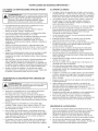
The purpose of safety symbols is to attract your attention to
possible dangers. The safety symbols, and their explanations,
deserve your careful attention and understanding. The safety
warnings do not by themselves eliminate any danger. The
instructions or warnings they give are not substitutes for proper
accident prevention measures.
SYMBOL
MEANING
DANGER:
Signals an EXTREME hazard.
Failure to obey a safety DANGER signal WILL result in
serious injury or death to yourself or to others.
WARNING:
Signals a SERIOUS hazard.
Failure to obey a safety WARNING signal CAN result in
serious injury to yourself or to others.
CAUTION:
Signals a MODERATE hazard.
Failure to obey a safety CAUTION signal MAY result in
property damage or injury to yourself or to others.
NOTE: Advises you of information or instructions
operation or maintenance of the equipment.
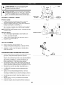
SPARK ARRESTOR NOTE
NOTE: For users on U.S. Forest Land and in the states of
California, Maine, Oregon and Washington. All U.S. Forest Land
and the state of California (Public Resources Codes 4442 and
4443), Oregon and Washington require, by law that certain internal
combustion engines operated on forest brush and/or grass-covered
areas be equipped with a spark arrestor, maintained in effective
working order, or the engine be constructed, equipped and
maintained for the prevention of fire. Check with your state or local
authorities for regulations pertaining to these requirements. Failure
to follow these requirements could subject you to liability or a fine.
This unit is factory equipped with a spark arrestor. Replacement
requires Muffler Assembly Part #753-05669, installed at a Sears
Parts & Repair Service Center.
CALiFORNiA
PROPOSITION
65
WARNING:
Engine exhaust, some of its constituents and
certain finished components contain or emit chemicals known
to the State of California to cause cancer and birth defects or
other reproductive harm. Wash hands after handling.
vital to the
Read the operator's manual and follow all warnings and safety
instructions. Failure to do so can result in serious injury to the
operator and/or bystanders.
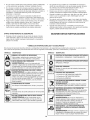
• iMPORTANT SAFETY iNSTRUCTiONS
READ ALL iNSTRUCTiONS
BEFORE OPERATING
Use the unit only in daylight or good artificial light.
Avoid accidental starting. Be in the starting position whenever
pulling the starter rope. The operator and unit must be in a stable
position while starting. Refer to Starting and Stopping.
Use the right tool. Only use this tool for its intended purpose.
Always hold the unit with both hands when operating. Keep a
firm grip on both handles or grips.
Keep hands, face, and feet away from all moving parts. Do not
touch or try to stop any moving parts while they are in motion.
I'1
WARNING:
When using the unit, all safety rules must be
followed. Please read these instructions before operating
the unit in order to ensure the safety of the operator and any
bystanders. Please keep these instructions for later use.
o
o
o
o
o
o
o
Read the instructions carefully. Be familiar with the controls and
proper use of the unit.
Do not operate this unit when tired, ill or under the influence of
alcohol, drugs or medication.
Children must not operate the unit. Teens must be accompanied
and guided by an adult.
Inspect the unit before use. Replace damaged parts. Check for
fuel leaks. Make sure all fasteners are in place and secure.
Replace parts that are cracked, chipped, or damaged in any way.
All guards and safety attachments must be installed properly
before operating the unit.
Be aware of risk of injury to the head, hands and feet.
Carefully inspect the area before starting the unit. Remove all
debris that can be thrown or become entangled with the unit,
such as rocks, glass, nails, wire, string, etc.
Clear the area of children, bystanders and pets; keep them
outside a 50-foot (15 m) radius, at a minimum. Even then, they are
still at risk from thrown objects. Encourage bystanders to wear
eye protection. If you are approached, stop the unit immediately.
Squeeze the throttle control and check that it returns
automatically to the idle position. Make all adjustments or
repairs before using the unit.
Do not touch the engine, gear housing or muffler. These parts get
extremely hot from operation, even after the unit is turned off.
Do not operate the unit faster than the speed needed to do the job.
Do not run the unit at high speed when not in use.
Always stop the unit when operation is delayed or when walking
from one location to another.
Do not force the unit. It will do a better, safer job when used at
the intended rate.
Do not overreach or use the unit from unstable surfaces such as
ladders, trees, steep slopes, rooftops, etc. Always keep proper
footing and balance.
If you strike or become entangled with a foreign object, stop the
engine immediately and check for damage. Do not operate
before repairing damage. Do not operate the unit with loose or
damaged parts.
Turn the engine to off and disconnect the spark plug for
maintenance or repair.
•
SAFETY WARNINGS FOR GAS UNITS
can explode if ignited.
the following
WARNING:
GasolineTake
is highly
flammableprecautions:
and its vapors
•
]
Store fuel only in containers specifically designed and approved
for the storage of such materials.
Always stop the engine and allow it to cool before filling the
tank. Never remove the fuel tank cap or add fuel when the
engine is hot. Always loosen the fuel tank cap slowly to relieve
any pressure in the tank before fueling.
Always add fuel in a clean, well-ventilated outdoor area where
there are no sparks or flames. DO NOT smoke.
Use only original equipment manufacturer (OEM) replacement
parts and accessories for this unit, as listed in the Parts List
section of this manual. Use of any other parts or accessories
could lead to serious injury to the user, or damage to the unit,
and void the warranty.
Keep the unit clean of vegetation and other materials that may
clog, gum or bind moving parts.
To reduce fire hazard, replace a faulty muffler and spark arrestor.
Keep the engine and muffler free from grass, leaves, excessive
grease or carbon build up.
BLOWER SAFETY
Do not insert anything into the air openings, blower tubes or
nozzle. Do not operate the unit if any of the air openings or
tubes are blocked. Keep the air openings free from dust, lint,
hair and anything else that may reduce airflow.
Do not operate the unit without the blower tubes attached.
Do not use the unit to spray liquids, especially flammable or
combustible liquids, such as gasoline. Do not use the unit in
areas where such liquids are present.
Do not use the unit for spreading chemicals, fertilizer or any
other substance that may contain toxic materials.
Do not set the unit down on any surface while the unit is
running. Debris can be picked up by the air intake and thrown
out the discharge opening, resulting in damage to the unit or
property or causing serious injury to bystanders or the operator.
During operation, never point the unit in the direction of people,
animals, windows or automobiles. Always direct blowing debris
away from people, animals, windows or automobiles.
Use extra caution when blowing debris near solid objects, such
trees, walls, fences, etc. When possible, blow away from such
objects, not toward them.
Never operate the unit without the fuel cap securely in place.
Avoid creating a source of ignition for spilled fuel. Wipe up any
spilled fuel from the unit immediately, before starting the unit.
Move the unit at least 30 ft. (9.1 m) from the fueling source and
site before starting the engine. DO NOT smoke.
Never start or run the unit inside a closed room or building.
Breathing exhaust fumes can kill. Operate this unit only in a well
ventilated outdoor area.
WHILE OPERATING
Wear safety glasses or goggles that meet current ANSi Z87.1
standards and are marked as such. Wear ear/hearing protection
when operating this unit. Wear a face or dust mask if the
operation is dusty.
Take care when working near valuable plants. The force of the
blown air could damage tender plants.
Wear heavy long pants, boots, gloves and a long sleeve shirt. Do
not wear loose clothing, jewelry, short pants, sandals or go
barefoot. Secure hair above shoulder level.
3
OTHER SAFETY WARNINGS
•
Stop the engine, make sure all moving parts have stopped, allow
the unit to cool and disconnect the spark plug wire before
performing any maintenence or replacing any parts on the unit.
Never store the unit with fuel in the tank, inside a building where
fumes may reach an open flame (pilot lights, etc.) or sparks
(switches, electrical motors, etc.).
Allow the engine to cool before storing or transporting. Be sure
to secure the unit while transporting.
Store the unit in a dry place, secured or at a height to prevent
unauthorized use or damage. Keep out of the reach of children.
Never douse or squirt the unit with water or any other liquid.
Keep handles dry, clean and free from debris. Clean after each
use, see Cleaning and Storage instructions.
Keep these instructions. Refer to them often and use them to
instruct other users. If you loan this unit to others, also loan
them these instructions.
SAVE THESE INSTRUCTIONS
,, SAFETY
& INTERNATIONAL
SYMBOLS
,,
This operator's manual describes safety and international symbols and pictographs that may appear on this product. Read the operator's
manual for complete safety, assembly, operating and maintenance and repair information.
SYMBOL
_
MEANING
SYMBOL
'_ ON/OFF STOP CONTROL
nd cates
danger,
warning
orcaution:
MaYbeusedin
o SAFETY ALERT SYMBOL
_
conjunction
MEANING
I
with other symbols or pictographs:
ON / START/RUN
' ON/OFF STOP CONTROL
WARNING:
Read the eperat0r's manual(s)and
READ all
OPERATOR'S
follow
warnings andMANUAL
safety instructionsl Failure to
do s0can result in serioUs injury t0 the operator
. and!or bystanders:
r_
_--IIII
WARNING:
Thrown
objectsPROTECTION
and
t _ ,,WEAR
EYE AND
HEARING
Iii cause Seve[e eye injury and hearing Iossl Wear eye
protection meeting Current ANSI Z87.1 standards and
ear protection when Operating this unit, Use a full face
shield when needed.
Push primer bulb, fully and slowly, 10 times.
' PRIMER BULB
._
,,_ 1, mCHOKE CONTROL
1. • FULL choke position
2. • PARTIAL choke position
3. • RUN choke position
p
,,UNLEADED
UEL
I_!1_ |
Always
use clean fresh un eaded fuel.
Refer to Operator,s manual for the proper type Of oil.
OFF or STOP
u
U
•"_7,*P.,dL _THROWN
_.."_,_
/
Mia.50ft(15m)"'KEEP BYSTANDERS AWAY
_e->lll
,,, DO NOT USE E85 FUEL IN THIS UNIT
greater than 10% ethanol will likely damage this
WARNING: It has been proven that fuel containing
engine and void the warranty.
OBJECTS CAN CAUSE SEVERE iNJURY
Small objects can be propelled at high
speed, causing injury.
WARNING:
R-
._
_1_,
WARNING:
-|_-
Keep all bystanders, especially children
and pets, at least 50 feet (15 m) from the operating area.
J HOT SURFACE
WARNING: Do not touch a hot muffler or cylinder.
You may get burned. These parts get extremely hot
from operation. When turned off they remain hot for a
' short time.
CAUSE SEVERE iNJURY
' WARNING:
LOWERS - ROTATING
IMPELLER
BLADES
CAN
Stop the engine
and allow
the impeller
to stop before changing tubes, cleaning or performing
any maintenance.
CRAFTSMAN
TWO
YEAR FULL
WARRANTY
FOR TWO YEARS from the date of purchase, this product is warranted
will receive free repair or replacement if repair is unavailable.
against any defects in material or workmanship.
For warranty coverage
visit the web site: www.craftsman.com
details to obtain free repair or replacement,
A defective product
This warranty covers ONLY defects in material and workmanship. Warranty coverage does NOT include:
•
Expendable items that can wear out from normal use within the warranty period, such as spark plugs or filters.
•
Product damage resulting from user attempts at product modification or repair or caused by product accessories.
•
Repairs necessary because of accident or failure to operate or maintain the product according to all supplied instructions.
•
Preventive maintenance, or repairs necessary due to improper fuel mixture, contaminated or stale fuel.
This warranty is void if this product is ever used while providing commercial services or if rented to another person.
This warranty gives you specific legal rights, and you may also have other rights which vary from state to state.
Sears Brands Management
Corporation,
Hoffman Estates, IL 60179
5
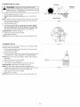
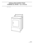
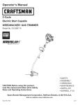
APPLiCATiONS
= Cleaning
yards,garages,
driveways,
porches,
patios,
around
walls,fencesandmore
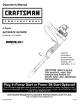
Air Filter
Cover
Choke Lever
Starter
Rope Grip
ASSEMBLY
TOOLS
•
=
REQUIRED:
Flat-head Screwdriver
T-20 Torx® Screwdriver
--
Fuel Cap
Shoulder Supports
Stand
Shoulder Support Buckles
Waist Support
On/Off
Switch
Spark Plug
Throttle Grip
Muffler
Waist Support Clip
Cruise Control
Flex Tube
Flare Nozzle
Control
Upper Blower
Tube
Lower Blower
Tube
Primer
Nozzle
Speed
Engine Type ........................................................................................
Displacement .......................................................................................
Blower Air Volume .......................................................................................
Blower Air Speed .......................................................................................
Valve Clearance .......................................................................
Spark Plug Gap ....................................................................................
Spark Plug .........................................................................
Lubrication ...............................................................................................
Crankcase Oil Capacity .................................................................................
Fuel Tank Capacity ......................................................................................
Approximate Unit Weight (No fuel) ..........................................................................
* All specifications are based on the latest product information
time without notice.
Start
TM
Port
Elbow Tube
Air-Cooled, 4-Cycle
32 cc (1.95 cu. in.)
up to 500 cfm
up to 150 mph
0.003 - 0.006 in. (0.076 - 0.152 mm)
Champion®
0.025 in. (0.635 mm)
RDZ4H or equivalent plug
SAE 30 Oil
3.04 oz. (90 ml)
26 oz. (769 ml)
15 Ibs. (6.8 kg)
available at the time of printing. We reserve the right to make changes at any
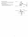
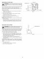
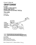
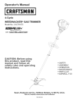
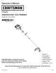
ASSEMBLING
THE BLOWER TUBE
Elbow Tube_
_S
Iw'o°'°O= oavoi
I
serious erso
damage to the unit, shut the unit off before removing or
installing blower tubes or nozzles.
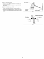
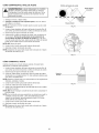
Installing the Flex Tube
1. Place a hose clamp around one end of the flex tube (Fig. 1).
2. Slide the flex tube and hose clamp onto the elbow tube (Fig. 1).
3. Tighten the screw on the hose clamp with a flat-head
screwdriver (Fig. 1).
Hose Clamp __
installing the Upper Blower Tube
Fig. 1
1. Place a hose clamp around the other end of the flex tube (Fig. 2).
2. Slide the flex tube and hose clamp onto the upper end of the
upper blower tube (Fig. 2).
3. Tighten the screw on the hose clamp with a flat-head
screwdriver (Fig. 2).
Installing the Lower Blower Tube
1. Align the bump on the upper blower tube with the bump slot on
the lower blower tube (Fig. 3).
2. Insert the upper blower tube into the lower blower tube (Fig. 3).
3. While holding the upper blower tube, twist the lower blower tube
clockwise until it locks into place (Fig. 3).
installing the Nozzle
1. Align the bump on the lower blower tube with the bump slot on
the nozzle (Fig. 4).
2. Insert the lower blower tube into the nozzle (Fig. 4).
3. While holding the lower blower tube, twist the nozzle clockwise
until it locks into place (Fig. 4).
Fig.2
_
Upper Blower Tube
Bump
,_._
Fig. 3
.__-----__---_
Lower Blower Tube
Bump
Bump
Slot
Nozzle
Fig.4
"_
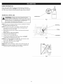
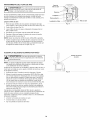
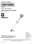
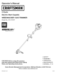
Securing
the Throttle Cables
Elbow Tube
1. Wrap a zip tie around the elbow tube and the throttle cables (Fig. 5).
2. Carefully tighten the zip tie. Do not crimp the throttle cables.
Adjusting
the Throttle
Grip
1.
Move the throttle grip to a location on the upper blower tube
that provides the best grip (Fig. 6).
2. Tighten the two screws on the throttle grip with a T-20 Torx®
screwdriver until the throttle grip is secure (Fig. 6).
ThrottJe CabJes
Zip Tie
Fig. 5
ThrottJe Grip
Lower Blower Tube
i'
Upper Blower Tube
x
_ZI,,
J;
#-j
Screws
Fig. 6
:i
USING THE RIGHT OiL
Use a high-quality SAE 30 weight oil of API (American Petroleum
institute) service class SJ. DO NOT use dirty oil. Failure to use clean
oil of the correct type can cause premature engine wear and failure.
Funnel Spout _(_
ADDING OIL: iNiTiAL USE
4hCycle
Motor
Oil
WARNING:
OVERFILLING THE CRANKCASE MAY
CAUSE SERIOUS PERSONAL iNJURY. Check the oil level
before each use. The importance of maintaining the proper
oil level cannot be overemphasized. Change the oil
according to the Maintenance Schedule.
Fig. 7
NOTE: This unit was shipped without oil in the crankcase. Oil must
be added before starting the unit.
NOTE: This unit comes with a 3.04 fluid oz. (90 ml) bottle of oil.
1. Unscrew the top of the oil bottle. Remove the paper seal.
Reinstall the top of the oil bottle.
2. Remove the cap from the oil bottle. Cut the tip off the funnel
spout (Fig. 7).
3. Set the unit on a fiat, level surface.
+_"
4. Unscrew the oil fill plug (Fig. 8).
5. Tilt the unit 30 ° to the side (Fig. 9).
6. Pour the entire bottle into the oil fill hole (Fig. 8). DO NOT
overfill. Refer to Checking the Oil Level.
NOTE: Never add oil directly to the fuel tank. This unit has a fourcycle engine. DO NOT mix oil with gasoline.
7. Wipe up any oil that may have spilled.
8. Reinstall the oil fill plug.
NOTE: Make sure the O-ring is in place on the oil fill plug (Fig. 8).
_
"_
Oil FiUHole
Fig.8
\\\
NOTE: Save the empty oil bottle. Use the bottle to measure the
correct amount of oil during future oil changes.
\
Fig. 9
9
Oil Fill Plug
USING THE RIGHT FUEL
The use of old fuel is the most common cause of performance
problems. Use only fresh, clean unleaded gasoline, or use TruFuel®
4-Cycle Fuel (PN 4727238).
Definition of Blended Fuels
Today's fuels are often a blend of gasoline and oxygenates such as
ethanol, methanol or MTBE (ether). Alcohol-blended fuel absorbs
water. As little as 1% water in the fuel can make fuel and oil
separate, forming acids when stored. ALWAYS use fresh fuel (less
than 30 days old).
NOTE: Dispose of old fuel according to federal, state and local
regulations.
Using Blended
Fuels
if using a blended fuel:
• Always use fresh unleaded gasoline
Use the fuel additive STA-BIL® or an equivalent
Drain the tank and run the engine dry before storing the unit
l
has been proven that fuel containing greater than 10%
__
1
I WARNING:
DOdamage
NOT USE
FUEL
THIS
It
|
ethanol will likely
this E85
engine
andINvoid
theUNIT.
warranty.
Using Fuel Additives
Use a fuel additive, such as STA-BIL Fuel Stabilizer or an
equivalent, to inhibit corrosion and minimize gum deposits. Add 0.8
oz. (23 ml) of fuel additive per gallon of fuel, according to the
instructions on the container. NEVER add fuel additives directly to
the unit's fuel tank.
FUELING THE UNIT
WARNING:
Gasoline is extremely flammable, ignited
vapors may explode. Always stop the engine and allow it
to cool before filling the fuel tank. Do not smoke while
filling the tank. Keep sparks and open flames at a distance
from the area.
WARNING:
Remove the fuel cap slowly to avoid injury
from fuel spray. Never operate the unit without the fuel cap
securely in place.
WARNING:
Add fuel in a clean, well ventilated outdoor
area. Wipe up any spilled fuel immediately. Avoid creating
a source of ignition for spilled fuel. Do not start the engine
until fuel vapors dissipate.
1.
2.
Position the unit with the fuel cap facing up.
Remove the fuel cap.
3.
Place the fuel container spout into the fill hole on the fuel tank
and fill the tank.
NOTE: Do not overfill the tank.
4. Wipe up any fuel that may have spilled.
5. Reinstall the fuel cap.
6. Move the unit at least 30 ft. (9.1 m) from the fuel container and
the fueling site before starting the engine.
10
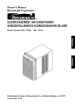
I_
_L_
On ( I ) / Start
!
outdoor area. Carbon monoxide exhaust fumes can be
I WARNING:
lethal in a confined
Operate
area.this unit only in a well-ventilated
serious injury, the operator and the unit must be in a stable
ARNING:
starting
position
when Avoid
pulling accidentally
the starter rope
(Fig.the
12).unit. To avoid
STARTING
SLOW
,_
Cruise Control --____ ,_____f_.__
Off (O)/Stop
J
INSTRUCTIONS
,hrottie
con
1. Check the oil level. Refer to Checking the Oil Level.
2. Fill the fuel tank. Refer to Fueling the Unit.
NOTE: There is no need to turn the unit on. The On/Off switch is in
the ON ( I ) position at all times (Fig. 10).
3. Slowly press and release the primer bulb 10 times (Fig. 11). If
fuel cannot be seen in the primer bulb, press and release the
primer bulb until fuel is visible.
4. Move the choke lever to Position 1 (Fig. 11).
NOTE: DO NOT squeeze the throttle control until step 9 (Fig. 10).
Fig. 10
Choke
Primer Bulb
Position 1
5. Crouch in the starting position (Fig. 12).
6. DO NOT squeeze the throttle control. Pull the starter rope with a
controlled and steady motion 5 times (Fig. 12).
NOTE: This unit uses the INCREDI-PULL TM starting system, which
significantly reduces the effort required to start the engine.
7. DO NOT squeeze the throttle control. Move the choke lever to
Position 2 (Fig. 11).
8. DO NOT squeeze the throttle control. Pull the starter rope with a
controlled and steady motion 3 to 5 times to start the engine.
9. Squeeze and hold the throttle control. Allow the engine to warm
up for 30 to 60 seconds.
10. Continue to squeeze the throttle control. Move the choke lever
to Position 3 (Fig. 11) and continue warming the engine for an
additional 60 seconds. The unit may be used during this time.
Lever
Position 3
Fig. 11
Starter Rope Grip
Starting
Position
NOTE: The engine is properly warmed up when it accelerates
without hesitation.
NOTE: Once the engine is properly warmed, the cruise control may
be adjusted and the throttle control can be used normally.
IF... the engine does not start, begin the starting procedure with
step 3.
IF... the engine fails to start after a few attempts, move the choke
lever to Position 3 and squeeze the throttle control. Pull the
starter rope with a controlled and steady motion 3 to 8 times.
The engine should start. If it does not, repeat this instruction.
IF... the engine is already warm, begin the starting procedure with
step 7.
Fig. 12
STOPPING INSTRUCTIONS
1.
Release the throttle control, or move the cruise control to the
SLOW position, and allow the engine to idle.
2. Press and hold the On/Off switch in the OFF (O) position until
the engine comes to a complete stop (Fig. 10).
11
NOTE:
This
unit can use a Speed Start TM Accessory!
Please refer to the Speed Start TM accessory operator's manual
for the proper use of this feature. (items Sold Separately! Refer
to the Speed Start TM Accessory section of this manual for more
information about these Speed Start TM accessories.)
STARTING iNSTRUCTiONS
1.
Check the oil level. Refer to Checking the 0il Level.
2. Fill the fuel tank. Refer to Fueling the Unit.
NOTE: There is no need to turn the unit on. The On/Off switch is in
the ON ( I ) position at all times (Fig. 10).
3. Slowly press and release the primer bulb 10 times (Fig. 11). If
fuel cannot be seen in the primer bulb, press and release the
primer bulb until fuel is visible.
4. Move the choke lever to Position 1 (Fig. 11).
NOTE: DO NOT squeeze the throttle control until step 11 (Fig. 10).
5. Crouch in the starting position (Fig. 12).
6. Insert the Speed Start TM accessory into the Speed Start TM port
(Fig. 26). Refer to the Operation section of the Speed Start TM
accessory operator's manual.
7.
8.
9.
DO NOT squeeze the throttle control.
accessory for 2 seconds.
DO NOT squeeze the throttle control.
Position 2 (Fig. 11).
DO NOT squeeze the throttle control.
accessory in intervals no longer than
unit starts.
Run the Speed Start TM
Move the choke lever to
Run the Speed Start TM
2 seconds each until the
10. Remove the Speed Start TM accessory from the unit.
11. Squeeze and hold the throttle control. Allow the engine to warm
up for 30 to 60 seconds.
12. Continue to squeeze the throttle control. Move the choke lever
to Position 3 (Fig. 11) and continue warming the engine for an
additional 60 seconds. The unit may be used during this time.
NOTE: The engine is properly warmed up when it accelerates
without hesitation.
NOTE: Once the engine is properly warmed, the cruise control may
be adjusted and the throttle control can be used normally.
iF... the engine does not start, begin the starting procedure with
step 3.
iF... the engine fails to start after a few attempts, move the choke
lever to Position 3 and squeeze the throttle control. Run the
Speed Start TM accessory in intervals no longer than 2 seconds
each until the unit starts. The engine should start. If it does not,
repeat this instruction.
iF... the engine is already warm, begin the starting procedure with
step 8.
STOPPING iNSTRUCTiONS
1.
Release the throttle control, or move the cruise control to the
SLOW position, and allow the engine to idle.
2. Press and hold the On/Off switch in the OFF (O) position until
the engine comes to a complete stop (Fig. 10).
12
operate the unitTowithout
blowerpersonal
tubes firmly
WARNING:
preventthe
serious
injury,installed.
never
]
Shoulder
Support
Straps
f Shoulder
Supports
(
protection to reduce the risk of injury when operating this unit. I
_WARNING:
Always
wearmask
eye, fhearing,
hand,
and body |
Wear a face mask
or dust
the operat
on foot
s dusty.
J
Waist
Support
Strap
Waist
Support
PUTTING ON AND TAKING OFF THE UNiT
Fig. 13
Putting On the Unit
1.
Place the shoulder supports over both shoulders. The engine
should rest securely on the operator's back.
2. insert one end of the waist clip into the other end until it locks
into place (Fig. 13).
3.
Pull the shoulder support straps down to tighten the shoulder
supports (Fig. 13). Pull the waist support strap to the left to
tighten the waist support (Fig. 13).
NOTE: Start the unit before putting it on. Refer to Starting and
Stopping.
Shoulder Support
Buckles
Taking Off the Unit
1.
Pull the tabs on the bottom of the shoulder support buckles up
to loosen the shoulder supports (Fig. 14). Pull the tab on the
waist clip up to loosen the waist support.
2. Squeeze the top and bottom of the waist clip to disconnect
waist clip (Fig. 14).
3. Remove the unit.
HOLDING
•
Fig. 14
the
THE UNiT
Stand in the operating position (Fig. 15).
Hold the throttle grip with the right hand. Keep the right arm
slightly bent.
Make sure the unit is secure and comfortable on the operator's
back.
Fig. 15
TiPS FOR BEST
RESULTS
Conserve water by using the blower instead of a hose to
perform many outdoor cleaning actions.
Operate the unit only at reasonable hours, not early in the morning
or late at night when people might be disturbed. Comply with
times listed in local ordinances. Usual recommendations are 9:00
a.m. to 5:00 p.m., Monday through Saturday.
To reduce noise levels, operate the unit at the lowest speed
needed to do the job. Limit the number of pieces of power
equipment used at any one time.
Use rakes or brooms to loosen debris before blowing.
In dusty conditions, slightly dampen surfaces.
Watch out for children, pets, open windows and freshly washed
cars. Blow debris safely away. Never direct the unit toward
anyone while the unit is in operation.
Use the nozzle to concentrate the air stream closer to the ground.
Use the cruise control to make continuous operation easier (Fig. 10).
Clean up after operation. Dispose of debris appropriately.
13
WARNING:
To prevent serious injury, never perform
maintenance or repairs while the unit is running. Always
allow the unit to cool before servicing or repairing the unit.
Disconnect the spark plug wire to prevent the unit from
starting accidentally.
MAINTENANCE
SCHEDULE
Perform these required maintenance procedures at the frequency
stated in the table. These procedures should also be a part of any
seasonal tune-up.
NOTE: Some maintenance procedures may require special tools or
skills. If unsure about these procedures, take the unit to a Sears
or other qualified service dealer. Call 1-800-4-MY-HOME
for
more information.
NOTE: Maintenance, replacement, or repair of the emission control
devices and system may be performed by a Sears or other qualified
service dealer. Call 1=800-4-MY-HOME for more information.
NOTE: Please read the California/EPA statement that came with the
unit for a complete listing of terms and coverage for the
emissions control devices, such as the spark arrestor, muffler,
carburetor, etc.
FREQUENCY
MAINTENANCE
REQUIRED
Every 10 hours
•
Clean and re-oil the air filter. Refer to
Maintaining the Air Filter.
After the first
10 hours and
every 25 hours
•
Change the oil. Refer to Changing the Off.
Check the rocker arm clearance. Refer to
Checking the Rocker Arm Clearance.
Check the spark plug condition and gap.
Refer to Maintaining the Spark Plug.
14
CHECKING THE OiL LEVEL
I_
Oil Fill Hole
Maximum
Oil Level
CAUSE SERIOUS PERSONAL INJURY. Check the oil level
before each use. The importance of maintaining the proper
_WARNING:
OVERFILLING THE CRANKCASE MAY
oil level cannot be overemphasized.
1. Stop the engine and allow it to cool.
2. Set the unit on a fiat, level surface,
table.
such as a workbench
or
Bottom
NOTE: Failure to keep the engine level may cause the oil to overfill.
3. Clean the area around the oil fill plug (Fig. 8) to prevent debris
from entering the oil fill hole.
4. Unscrew the oil fill plug.
5. Look into the oil fill hole; use a flashlight if necessary. The oil
level should just touch the bottom thread of the oil fill hole
(Fig. 16). If the oil level is too low, add oil to the oil fill hole until
the oil level touches the bottom thread of the oil fill hole.
NOTE: DO NOT overfill the crankcase.
Thread
Fig. 16
6. Wipe up any oil that may have spilled.
7. Reinstall the oil fill plug.
NOTE: Make sure the O-ring is in place on the oil fill plug (Fig. 8).
CHANGING
THE OiL
Fig. 17
Change the oil while the engine is still warm. The oil will flow freely
and carry away more impurities.
1. Clean the area around the oil fill plug (Fig. 8) to prevent debris
from entering the oil fill hole.
2. Unscrew the oil fill plug.
3. Tip the unit to the side to pour the oil out of the oil fill hole and into
a container (Fig. 17). Allow ample time for complete drainage.
NOTE: Dispose of the old oil according to federal, state and local
regulations.
4. Wipe up any oil that may have spilled.
5. Tilt the unit 30 ° to the side (Fig. 9).
6. Pour 3.04 fl.oz. (90 ml) of SAE 30 SJ oil into the oil fill hole.
FlU Line
NOTE: DO NOT overfill. Refer to Checking the Oil Level.
NOTE: Use the empty oil bottle saved from the initial use to
measure the correct amount of oil. Fill the bottle to the top of the
label to approximate 3.04 fl.oz. (90 ml) of oil (Fig. 18).
7. Wipe up any oil that may have spilled.
8. Reinstall the oil fill plug.
NOTE: Make sure the O-ring is in place on the oil fill plug (Fig. 8).
Fig. 18
15
MAiNTAiNiNG
THE AiR FILTER
Air Filter Cover --
the engine and allow it to cool before cleaning or maintaining
To avoid serious personal injury, always stop
[_J
WARNING:
the unit.
J
Failure to maintain the air filter can result in poor performance or can
cause permanent damage to the engine. Engine failure due to
improper air filter maintenance is not covered by the product warranty.
Cleaning
Slots
Back_
the Air Filter
Air Filter
Lock Tab
1.
Remove the air filter cover: press in the lock tab and swing the
air filter cover up (Fig. 19).
2. Remove the air filter (Fig. 19).
3. Wash the air filter in detergent and water. Rinse the air filter
thoroughly and allow it to dry.
4. Lightly coat the air filter with clean SAE 30 oil.
Fig. 19
5. Squeeze the air filter to spread and remove excess oil.
6. Reinstall the air filter (Fig. 19).
NOTE: Operating the unit without the air filter and air filter cover will
VOID the warranty.
7. Reinstall the air filter cover: place the slots on the air filter cover
onto the tabs on the backplate. Swing the air filter cover down
and press it closed until the lock tab snaps into place (Fig. 19).
ADJUSTING THE iDLE SPEED
Idle Speed Screw
L_J
safety
instructions
prevent serious
injury. all
ARNING:
Weartoprotective
clothingpersonal
and observe
J
NOTE: Careless adjustments can seriously damage the unit. A Sears or
other qualified service dealer should make carburetor adjustments.
If, after checking the fuel and cleaning the air filter, the engine still
will not idle, adjust the idle speed screw as follows:
1. Start the engine. Refer to Starting and Stopping.
2. Move the cruise control to the SLOW position and let the engine
idle. If the engine stops, use a small Phillips screwdriver to turn the
idle speed screw clockwise, 1/8 of a turn at a time (as needed)
until the engine idles smoothly (Fig. 20).
3. If the engine is idling too quickly, turn the idle speed screw
counterclockwise, 1/8 of a turn at a time (as needed) to reduce the
idle speed (Fig. 20).
Fig. 20
Checking the fuel, cleaning the air filter, and adjusting the idle speed
should solve most engine problems. If not, and any of the following
conditions are true, take the unit to a Sears or other qualified service
dealer:
•
the engine will not idle
the engine hesitates or stalls on acceleration
there is a loss of engine power
16
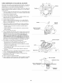
CHECKING THE ROCKER ARM CLEARANCE
This adjustment requires disassembly of the engine. If you feel
unsure or unqualified to perform this, take the unit to a Sears or
other qualified service dealer.
The engine must be cold when checking or adjusting the rocker arm
clearance. This task should be performed inside, in a clean, dustfree area.
1.
Screws
Screws
Remove the 7 screws from the engine cover with a flat-head
screwdriver or T-25 Torx screwdriver (Fig. 21). Remove the
engine cover.
2. Disconnect the spark plug wire.
3. Clean the area around the spark plug.
4. Remove the spark plug from the cylinder with a 5/8 in. socket,
turning counterclockwise.
5. Clean the rocker arm cover.
6. Remove the screw from the rocker arm cover with a flat-head
screwdriver or T-25 Torx screwdriver (Fig. 22). Remove the
rocker arm cover and gasket (Fig. 23).
7. Look into the spark plug hole (Fig. 22) and pull the starter rope
slowly to move the piston. Make sure:
• The piston is at the top of its travel (top dead center)
/
/
Fig. 21
Screw
Both rocker arms move freely and both valves are closed
If these statements are not true, repeat this step.
8. Use a feeler gauge to measure the clearance between one of the
valve stems and its corresponding rocker arm (Fig. 24). Repeat
this process for the other valve stem and rocker arm. The
recommended clearance is 0.003- 0.006 in. (0.076- 0.152 ram).
Use a standard automotive 0.005 in. (0.127 ram) feeler gauge.
The feeler gauge should slide between the rocker arm and valve
stem with a slight amount of resistance, without binding (Fig. 24).
9. If the clearance is not within specification:
a. Turn the adjusting nut with a 5/16 inch (8 mm) wrench or nut
driver (Fig. 24).
To increase clearance, turn the adjusting nut
counterclockwise.
10.
11.
12.
13.
Rocker
Arm Cover
Spark Plug Hole
Fig. 22
Adjusting Nuts
iNTAKE
EXHAUST
To decrease clearance, turn the adjusting nut clockwise.
b. Recheck both clearances and adjust as necessary.
Install a new gasket and reinstall the rocker arm cover. Torque
the screw to: 20--30 in_lb (2.2-3.4 N_m).
Inspect and reinstall the spark plug. Refer to Maintaining the
Spark Plug.
Reconnect the spark plug wire.
Reinstall the engine cover. Check the alignment of the engine
cover before tightening the screws. Tighten the screws.
Gasket
Rocker
Fig. 23
Adjusting Nut
Feeler Guage
0.003 = 0.006 in.
(0.076 = 0.152 ram)
Valve
Fig. 24
17
Stem
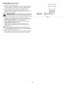
MAiNTAiNiNG
THE SPARK
PLUG
1.
2.
Stop the engine and allow it to cool.
Remove the 7 screws from the engine cover with a flat-head
screwdriver or 7--25Torx screwdriver (Fig. 21). Remove the
engine cover.
3.
4.
Grasp the spark plug boot firmly and pull it from the spark plug.
Clean around the spark plug. Remove the spark plug from the
cylinder head with a 5/8-inch socket, turning counterclockwise.
\
0.025 in.
J._J
electrodes.
the sand
engine
could
damage
the cylinder.
ARNING: GritDoin not
blast,
scrape
or clean
spark plug
J
5.
Inspect the spark plug. If the spark plug is cracked, fouled or
dirty, replace it with a replacement part #753-05784, a
Champion RDZ4H or an equivalent spark plug.
6. Use a feeler gauge to set the air gap at 0.025 in. (0.635 ram}
(Fig. 25).
7. Install the spark plug in the cylinder head. Tighten the spark plug
with a 5/8-inch socket, turning it clockwise until snug.
NOTE: If using a torque wrench, torque to:
8.
9.
110=120 in.oib. (12.3-13.5 N.rn). Do not over tighten.
Reattach the spark plug boot.
Reinstall the engine cover. Check the alignment of the engine
cover before tightening the screws. Tighten the screws.
18
(0.635 ram}
Fig. 25
CLEANING
STO RAG E
•
the engine and allow it to cool before cleaning or maintaining
To avoid serious personal injury, always stop
WARNING"
the unit.
]
Use a small brush to clean the outside of the unit. Do not use strong
detergents. Household cleaners that contain aromatic oils such as
pine and lemon, and solvents such as kerosene, can damage plastic.
Wipe off any moisture with a soft cloth.
Never store a fueled unit where fumes may reach an open flame
or spark.
Allow the engine to cool before storing.
Lock up the unit to prevent unauthorized use or damage.
Store the unit in a dry, well-ventilated area.
Store the unit out of the reach of children.
Long=term Storage
1. Remove the fuel cap, tip the unit and drain the fuel into an
approved container. Reinstall the fuel cap.
2. Start the engine and allow it to run until it stalls. This ensures
that all fuel has been drained from the carburetor.
3. Allow the engine to cool. Remove the spark plug and put 5 drops
of any high quality motor oil into the cylinder. Pull the starter rope
slowly to distribute the oil. Reinstall the spark plug.
4. Thoroughly clean the unit and inspect it for any loose or
damaged parts. Repair or replace damaged parts and tighten
loose screws, nuts or bolts.
Preparing the Unit for Use after Long=term
Storage
1. Remove the spark plug and drain all of the oil from the cylinder.
2. Change the oil. Refer to Changing the Off.
NOTE: Do not use fuel that has been stored for more than 30 days.
Dispose of old fuel and oil according to federal, state and local
regulations.
19
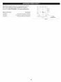
Thisunitcanbestartedwithanoptional
SpeedStart
TM
accessory
(items sold separately). Please contact your local Craftsman retailer,
call 1-800-4-MY-HOME®
or visit www.craftsman.com
for more
information.
item No.
316.85951
316.85952
316.85953
Description
..............................
..................................
.............................
Plug-In Power Start
Power Bit Start
Cordless Power Start
Speed Start TM
Port
Fig. 26
20
PROBLEM
SOLUTION
The primer bulb was not pressed enough
Press the primer bulb 10 times or until fuel is visible
The spark plug is fouled
Replace the spark plug
The fuel is old (over 30 days)
Drain the fuel tank and add fresh fuel
The fuel is old (over 30 days)
Drain the fuel tank and add fresh fuel
,
.
i
The fuel is old (over 30 days)
Drain the fuel tank and add fresh fuel
The spark plug is fouled
Replace the spark plug
HELP?
o Find this
and all your other
_ Get answers
from our team
_ Get a personalized
_, Find information
product
manuals
of home
experts.
maintenance
plan
for your home.
and too_s to he_p with
home projects.
'°°"'°"
brought
online.
to you by Seals
21
Congratulations on making a smart purchase. Your new Craftsman@ product is designed and manufactured for years of dependable
operation. But like all products, it may require repair from time to time. That's when having a Repair Protection Agreement can save you
money and aggravation.
Here's what the Repair Protection Agreement*
includes:
[]
Expert service
[]
[]
[]
Unlimited service and no charge for parts and labor on all covered repairs
Product replacement up to $1500 if your covered product can't be fixed
Discount of 25% from regular price of service and related installed parts not covered by the agreement; also, 25% off regular price of
preventive maintenance check
Fast help by phone - we call it Rapid Resolution - phone support from a Sears representative. Think of us as a "talking owner's manual."
[]
by our 10,000 professional repair specialists
Once you purchase the Repair Protection Agreement, a simple phone call is all that it takes for you to schedule service. You can call anytime
day or night, or schedule a service appointment online.
The Repair Protection Agreement is a risk-free purchase. If you cancel for any reason during the product warranty period, we will provide a
full refund. Or, a prorated refund anytime after the product warranty period expires. Purchase your Repair Protection Agreement today!
Some limitations and exclusions apply. For prices and additional information in the U.S.A. call 1-800-827-6655.
*Coverage in Canada varies on some items. For full details call Sears Canada at 1-800-361-6665.
Sears installation Service
For Sears professional instaflation of home appliances,
Canada call 1-800-4-MY-HOME.
garage door openers, water heaters, and other major home items, in the U.S.A. or
22
Manual
del Operador
M
Motor de 4 tiernpos
Con Posibilidad de Arranque El_ctrico
SOPLADOR
DE MOCHILA
Modelo No. 316.794011
U_F_VABLE
$7_A_T_G
EA $ E _
o SEGURIDAD
o ENSAMBLAJE
o OPERACION
PRECAUCION: Antes de utilizar, este
producto lea este manual y siga todas
las reglas de seguridad
e instrucciones
de operaci6n.
Sears Brands Management
Corporation,
Visite nuestro
769-08046 P00
o MANTENIMIENTO
LISTA DE PIEZAS
Hoffman
Estates, IL 60179 U.S.A.
sitio web: www.craftsrnan.corn
05/12
TABLA DE CONTENIDO
Seguridad ...........................................
Garantia .............................................
Conozca su unidad ....................................
24
27
28
Especificaciones
......................................
Ensamblaje ..........................................
Aceite y combustible ...................................
Arranque y parada .....................................
Operaci6n ...........................................
Mantenimiento ........................................
28
29
31
33
35
36
Limpieza y almacenamiento
.............................
41
Accesorio Speed Start TM ................................
42
Localizaci6n y soluci6n de problemas .....................
43
Convenio de protecci6n de reparaci6n .....................
44
Lista de piezas .......................................
46
NQmeros de servicio .........................
Contraportada
Toda la informaci6n, las ilustraciones y especificaciones que contiene
este manual se basan en la informaci6n mas reciente del producto,
existente en el momento de la impresi6n. Nos reservamos el derecho
de hacer cambios en cualquier momento, sin previo aviso.
NOTA SOBRE EL PARACHISPAS
El prop6sito de los simbolos de seguridad es Ilamar la atenci6n
sobre posibles peligros. Los simbolos de seguridad y sus
explicaciones merecen toda su atenci6n y comprensi6n. Las
advertencias de seguridad no eliminan de por si ningQn peligro.
Las instrucciones o advertencias que dan no sustituyen las
medidas adecuadas de prevenci6n de accidentes.
SJMBOLO
NOTA: Para usuarios de la Zona Forestal de EE. UU., y los
estados de California, Maine, Oreg6n y Washington. Todas las
zonas forestales de EE.UU., asi como los estados de California
(C6digos de Recursos PQblicos 4442 y 4443), Oreg6n y Washington
exigen, por ley, que determinados motores de combusti6n interna
operados en matorrales boscosos y/o zonas cubiertas de hierba,
esten equipados con un parachispas y se mantengan en buen estado
de funcionamiento, o que el motor sea construido, equipado y
mantenido con vista a la prevenci6n de incendios. Compruebe con
las autoridades de su estado o Iocalidad las reglamentaciones
relacionadas con estos requisitos. Si no cumple estos requisitos
podria estar sujeto a responsabilidad civil o multa. Esta unidad viene
equipada de fAbrica con un parachispas. El reemplazo requiem la
pieza No. 753-05669 del conjunto del silenciador, instalada en un
Centro de Piezas y Servicio de Reparaciones de Sears.
SlGNIFICADO
PELIGRO:
Indica un peligro EXTREMO.
El no obedecer una sehal de seguridad de PELIGRO
TRAERA COMO CONSECUENClA que usted u otras
personas puedan sufrir lesiones graves o la muerte.
ADVERTENCIA:
Indica un peligro GRAVE.
El no obedecer una sehal de ADVERTENClA de seguridad
PUEDE conducir a que usted u otras personas sufran
graves lesiones.
PRECAUCl0N:
PROPOSlCION
ADVERTENClA:
Los gases de escape, algunos de sus
componentes y determinados productos terminados
contienen o emiten productos quimicos de los que el estado
de California tiene conocimiento provocan cancer,
malformaciones congenitas u otros da_os al sistema
reproductor. Lavese las manos despues de manipularlos.
Indica un peligro MODERADO.
El no obedecer una sehal de PRECAUCION de seguridad
PUEDE conducir a dahos a la propiedad o a que usted u
otras personas se lesionen.
NOTA" Indica informaci6n o instrucciones de vital importancia
la operaci6n o el mantenimiento del equipo.
65 DEL ESTADO DE CALiFORNiA
para
Lea el manual del operador y siga todas las advertencias e
instrucciones de seguridad. No hacerlo puede ocasionar
lesiones graves al operador y/o a las personas presentes.
24
• INSTRUCCIONES
LEA TODAS LAS INSTRUCCIONES
LA UNIDAD
_
•
DE SEGURIDAD
ANTES DE OPERAR
Use gafas o lentes de seguridad que cumplan con las normas
actuales ANSI Z87.1 y esten marcados como tales. Use siempre
protecci6n para los oidos al operar esta unidad. Si la operaci6n
levanta polvo, Ileve puesta una mascara facial o contra el polvo.
Use pantalones largos y gruesos, botas, guantes y camisa de
mangas largas. No use ropa holgada, alhajas, pantalones
cortos, sandalias ni ande descalzo. Asegure su cabello por
encima del nivel de los hombros.
Use la unidad Qnicamente a la luz del dia o con buena luz artificial.
Lea detenidamente las instrucciones. Familiaricese con los
controles y el uso adecuado de la unidad.
No opere esta unidad siesta cansado, enfermo o bajo los
efectos del alcohol, drogas o medicamentos.
Evite los arranques accidentales. P6ngase en la posici6n de
arranque siempre que tire de la cuerda. El operador y la unidad
deben estar en una posici6n estable durante el arranque.
Consulte la secci6n Arranque y Parada.
Use la herramienta correcta. Use esta herramienta solamente
con el prop6sito previsto.
Sostenga siempre la unidad con ambas manos al operarla.
Agarre firmemente ambos mangos o empu_aduras.
Mantenga las manos, la cara y los pies lejos de todas las partes
m6viles. No trate de tocar ni detener ninguna de las piezas
m6viles mientras esten girando.
No toque el motor, el bastidor del engranaje ni el silenciador.
Estas partes se ponen extremadamente calientes durante la
operaci6n y aQn despues de apagada la unidad.
No opere la unidad a una velocidad mayor que la necesaria para
realizar el trabajo. No ponga a funcionar la unidad a alta velocidad
si no la esta usando.
deben
Inspeccione la unidad antes de utilizarla. Reemplace las piezas
dar_adas. Verifique que no haya fugas de combustible.
AsegOrese de que todos los sujetadores esten en su sitio y
asegurados. Cambie las piezas rajadas, melladas o dar_adas de
cualquier forma.
Todos los accesorios de protecci6n y seguridad deben estar
instalados adecuadamente antes de comenzar a operar la unidad.
Tenga en cuenta el riesgo de lesiones a la cabeza, las manos y
los pies.
Inspeccione cuidadosamente el Area antes de encender la unidad.
Retire todas los escombros que puedan salir despedidos o
enredarse en la unidad, como piedras, vidrios, clavos, alambres,
cuerdas, etc.
Aleje a los ni_os, personas presentes y animales domesticos del
Area; mantengalos fuera de un radio de 50 pies (15 m) como
minimo. AOn asi es posible que se arriesguen a ser golpeados por
los objetos lanzados. Sugiera a los presentes usar protecci6n para
los ojos. Si alguien se le acerca, pare la unidad inmediatamente.
Apriete el control del regulador y compruebe que regresa
automaticamente a la posici6n de marcha en vacio. Haga todos
los ajustes o reparaciones antes de usar la unidad.
ADVERTENCIAS
GASOLINA
DE SEGURIDAD
PARA UNIDADES
Apague siempre la unidad cuando la operaci6n se demore o al
caminar de un lugar a otro.
DE
y, de prenderse, sus vapores pueden hacer expos 6n.
|
ADVERTENCIA:
La gasolina es sumamente inflamable
Tome las siguientes precauciones:
J
Almacene el combustible solo en los recipientes diser_ados y
aprobados especificamente para estos materiales.
Pare siempre el motor y deje que se enfrie antes de Ilenar el
tanque. Nunca quite la tapa del tanque de combustible ni eche
combustible cuando el motor este caliente. Antes de Ilenar el
tanque, siempre afloje la tapa lentamente para disipar la presi6n
del mismo.
Siempre agregue el combustible en un Area exterior bien
ventilada y limpia, donde no haya chispas ni llamas. NO fume.
No opere nunca la unidad si la tapa del combustible
bien asegurada en su lugar.
•
AL OPERAR LA UNIDAD
las normas de seguridad. Lea estas instrucciones antes de
operar la unidad a fin de garantizar la seguridad del
I
operador
y de cualquier
otra la
persona
Guardetodas I
DVERTENCIA:
AI usar
unidad presente.
deben seguirse
estas instrucciones para poder usarlas mas adelante,
j
Los nitros no deben operar la unidad. Los adolescentes
estar acompa_ados y supervisados pot un adulto.
IMPORTANTES
No fuerce la unidad. Hara un trabajo mejor y mas seguro a la
velocidad para la que fue dise_ada.
No intente alcanzar demasiado lejos la unidad ni la use parado
en superficies inestables como escaleras, arboles, pendientes
pronunciadas, techos, etc. Mantenga siempre una posici6n y
equilibrio adecuados.
Si golpea o se enreda con un objeto extra,o, pare de inmediato
el motor y verifique si hay algQn da_o. No ponga a funcionar el
equipo sin reparar el da_o. No opere la unidad si hay piezas
flojas o da_adas.
Apague el motor y desconecte la bujia para darle mantenimiento
o hacer reparaciones.
Utilice solamente las piezas de repuesto y accesorios del
fabricante original que se listan en la secci6n Lista de piezas de
este manual. El uso de cualquier pieza o accesorio no
autorizado podria causar lesiones graves al usuario o da_os a la
unidad y anular la garantia.
Mantenga la unidad limpia de vegetaci6n y otros materiales que
puedan obstruir, pegar o atorar las piezas en movimiento.
Para evitar el peligro de incendio, reemplace el silenciador y
parachispas defectuosos. Mantenga el motor y el silenciador sin
hierbas, hojas, grasa excesiva y sin acumulaci6n de carb6n.
SEGURIDAD
no esta
DE LA SOPLADORA
No inserte nunca ningOn objeto en las aberturas de aire, los
tubos de la sopladora o la boquilla. No opere nunca la unidad si
alguna de las aberturas de aire, o tubos estan bloqueados.
Mantenga las aberturas de aire libres de polvo, hilachas,
cabellos o cualquier cosa que pueda disminuir el flujo de aire.
No opere nunca la unidad sin los tubos de la sopladora puestos.
No use nunca la unidad para rociar liquidos, especialmente
liquidos inflamables o combustibles, como gasolina. No utilice la
unidad en Areas donde tales liquidos esten presentes.
Evite el peligro de incendio debido a combustible derramado.
Limpie de inmediato todo combustible derramado de la unidad
antes de encenderla. Antes de arrancar el motor, aleje la unidad
a una distancia de 30 pies (9.1 m) como minimo del lugar de
abasto de combustible. NO fume.
No arranque ni use nunca la unidad dentro de una habitaci6n o
edificio cerrados. Inhalar los gases de escape puede ser fatal.
Opere esta unidad solamente en un Area exterior bien ventilada.
25
• Nousenunca
launidad
pararociarproductos
quimicos,
fertilizantes
uotrassustancias
quepuedan
contener
materiales
t6xicos.
Nocoloque
launidad
sobreninguna
superficie
mientras
este
funcionando.
Latomadeairepodriarecoger
residuos
quealser
lanzados
atraveslaabertura
dedescarga,
dafiarian
launidad,
la
propiedad
u ocasionarian
lesiones
graves
alaspersonas
presentes
o aloperador.
AIoperarla,
noapuntenuncalasopladora
endirecci6n
de
personas,
animales,
ventanas
o autom6viles.
Dirijasiempre
los
residuos
lejosdelaspersonas,
animales,
ventanas
oautom6viles.
Tenga
mucho
cuidado
cuando
sopleresiduos
cercadeobjetos
s61idos
comoarboles,
paredes,
cercas,
etc.Cuando
sea
posible,
soplelejosdetalesobjetos,
nuncahaciaellos.
Tenga
cuidado
cuando
trabajecercadeplantas
valiosas.
La
fuerzadelairesoplado
podriadafiarlasplantas
delicadas.
OTRAS ADVERTENCIAS
Noguarde
nuncalaunidad
concombustible
eneltanque
ni
dentro
deunaedificaci6n
enlaquelosgases
puedan
ponerse
encontacto
conunallamaexpuesta
(luces
piloto,etc.)o
chispas
(interruptores,
motores
electricos,
etc.).
Espere
a queelmotorseenfrieparaguardar
o transportar
la
unidad.
Cerci6rese
deasegurar
bienlaunidad
altransportarla.
Guarde
launidad
enunlugarseco,bajoIlaveo enalto,afinde
evitarsuusonoautorizado
o dafio.Mantengala
fueradel
alcance
delosnifios.
Nomojenirocielaunidad
conaguaniconningQn
otroliquido.
Mantenga
losmangos
secos,limpios
ysinsuciedades.
Limpie
la
unidad
despues
decadauso,consulte
lasinstrucciones
de
Limpieza y almacenamiento.
Guarde estas instrucciones. ConsQItelas con frecuencia y
utilicelas para instruir a otros usuarios. Si le presta esta unidad a
alguien, prestele tambien estas instrucciones.
GUARDE
DE SEGURIDAD
ESTAS INSTRUCCIONES
Detenga el motor, asegQrese de que todas las piezas m6viles
esten detenidas, deje que la unidad se enfrie y desconecte la
bujia antes de realizar cualquier mantenimiento o reemplazar
piezas en la unidad.
• SJMBOLOS
INTERNACIONALES
Y DE SEGURIDAD
•
Este manual del operador describe simbolos y pictografias internacionales y de seguridad que posiblemente aparezcan en este producto.
Lea el manual del operador para informarse bien sobre la seguridad, ensamblaje, operaci6n, mantenimiento y reparaci6n.
SJMBOLO
SIGNIFICADO
SJMBOLO
• SJMBOLO DE ALERTA DE SEGUR!DAD
!ndica pelJgro, advertencia o precauc!6n; puede
utilizarse junto a otros simbolos o pictografias ......
_1
' CONTROL DE ENCENDIDO/APAGADO
I
ADVERTENCIA:
Lea el o los manuaies del
operador
LEA EL MANUAL
Y siga todas
DELlas
OPERADOR
advertenCias e instruCcioneS
de seguddad_ No hacedo puede ocasionar lesiones
graves a! operador y/o a!as personas presentes,
O
|
APAGADO o PARADA
' CONTROL DE ENCENDIDO/APAGADO
. 2 • Posici6n de OBTURACION
3 • Posici6n de MARCHA
,. I,,,,,
_._"
,COMBUST BLES
PLOMO
N
DE PARADA
-_S "_
, LOS OBJETOS DESPEDIDOS
GRAVES
LESIONES
PARClAL
PUEDEN CAUSAR
ADVERTENClA:
Los objetos pequefios pueden
, ser lanzados a gran veloc_dad y ocaslonar leslones.
Use siemp!e c£ mbustib!e fresc0, !!mpio YSi n P!0m0:
_
o ACEITE
consUlte el tipo de aCeite adecuado ene! manual de!
operador:
, NO USE COMBUSTIBLE
_,
(_ _
"_
ENCENDIDO / ARRANQUE / FUNCIONAM ENTO
I
i._l i,_l i{ol, CONTROL DEL OBTURADOR
1 o Posici6n de OBTURACION COMPLETA
, con las n0rmas actua!es ANSIZ87.!;y
protecci6n
' para 10Soidos, Deser necesado, use un Protector
facial comp!eto.
_J
DE PARADA
Optima 10 veces la pera del cebador, lentamente y
' PERA
DEL CEBADOR
por completo.
ADVERTENCIA:
EoSobjetoS lanzados Ye!
fuerte
pueden
0casionar
lesi0nes
gravesY aOJDOS
los ojos y
,,,USE PROTECCION PARA
LOS OJOS
p6rdida de !a audici6n: Siempre que opere esta
v unidad, use gafas 0 !entes de seguddad que cutu!!an
__j_
SIGNIFICADO
ADVERTENCIA:
_
Min. 50ft (15m) '
MANTENGA
ALEJADOS
A LOS PRESENTES
_1_
ADVERTENC'A:
Mantenga
a todosdom6sticos,
los presentes,
especialmente a los nifios
y animales
a
una distancia de al menos 50 pies (15 m).
E85 EN ESTA UNIDAD
sefia compiobado quees
SUPERFICIE CALIENTE
cilindro calientes. Podria
quemarse.
Estas partes
ADVERTENCIA:
No toque
un silenciador
o se
ponen extremadamente calientes durante la
operaci6n. Despu6s de apagada la unidad, se
mantendr4n calientes durante un rato.
probable que el Combustible con rnAs de 10%
. etanol dafie este motor, Io que anular4 la garantia:
SOPLADORASLA ASPAS GIRATORIAS DEL
IMPELENTE PUEDEN OCASIONAR LESIONES
GRAVES
ADVERTENCIA:
Detenga el motor y espere a que
el impelente se detenga antes de cambiar los tubos,
limpiar o Ilevar a cabo cualquier mantenimiento.
26
GARANTJA
TOTAL
POR DOS A_IOS CRAFTSMAN
Este producto se garantiza POR DOS ANOS a partir de la fecha de compra, contra cualquier defecto de materiales o mano de obra. Un
producto defectuoso se reparara sin costo alguno o se remplazara si no es posible repararlo.
Para conocer
los detaiies
de la cobertura
de garantia
para la reparaci6n
o reemplazo
gratuitos,
visite el sitio web: www.craftsman.com
Esta garantia cubre SOLAMENTE defectos de materiales o mano de obra. La cobertura de garantia NO incluye:
•
Los articulos consumibles que se desgasten debido al uso normal dentro del periodo de garantia, como bujias o filtros.
•
Los dados al producto a consecuencia de intentos de modificaci6n o reparaci6n del usuario u ocasionados por accesorios del producto.
•
Las reparaciones necesarias por un accidente o por no operar o mantener el producto de acuerdo con todas las instrucciones suministradas.
•
El mantenimiento preventivo ni las reparaciones necesarias debido a una mezcla incorrecta de combustible o a al uso de un combustible
viejo o contaminado.
Esta garantia se anula si el producto en algL_nmomento se utiliza para prestar servicios comerciales o se alquila a otra persona.
Esta garantia le confiere a usted derechos legales especificos y usted puede tener, ademas, otros derechos que difieren de un estado a otro.
Sears Brands Management
Corporation,
Hoffman Estates, iL 60179
27
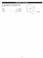
usos
•
Limpieza de patios, garajes, entrada de autos, p6rticos,
terrazas, aceras, derredores de muros, cercas y otros
Tapa del
filtro de aire
Palanca del
obturador
Agarre de la
cuerda de arranque
HERRAMIENTAS NECESARIAS PARA
EL ENSAMBLAJE:
Destornillador
Destornillador
piano
Torx® -I--20
Tapa del tanque
de combustible
Tirantes
Hebillas
del tirante
Soporte para
la cintura
Interruptor
de
Encendido / Apagado
Bujia de
encendido
Empuhadura
del regulador
Silenciador
Control
Clip del soporte
para la cintura
de crucero
Tubo flexible
Control
Boquilla
ancha
del
regulador
Tubo superior
de la sopladora
Tubo inferior de
la sopladora
Tapbn de Ilenado
de
BoquiUa
Puerto Speed Start
Tipo de motor .............................................................................
Cilindrada ....................................................................................
Volumen de aire de la sopladora ............................................................................
Velocidad de aire de la sopladora ..........................................................................
Holgura de las v_.lvulas ............................................................
Abertura de la bujia ............................................................................
Bujia de encendido ..................................................................
Lubricaci6n ............................................................................................
Tubo acodado
TM
Enfriado pot aire, de 4 tiempos
32 cc (1.95 pulg. cQbicas)
hasta 500 cfm
hasta 150 mph
0.003 - 0,006 pulgadas (0.076 - 0.152 mm)
0.025 pulgadas (0.635 mm)
Bujia Champion® RDZ4H o equivalente
Aceite SAE 30
Capacidad de aceite del carter .........................................................................
Capacidad del tanque de combustible ....................................................................
Peso aproximado de la unidad (sin combustible) .............................................................
3.04 onzas (90 ml)
26 onzas (769 ml)
15 libras (6.8 kg)
* Todas las especificaciones se basan en la informaci6n del producto ma.s reciente disponible en el momento de la impresi6n. Nos reservamos
el derecho de hacer cambios en cualquier momento, sin previo aviso.
28
ENSAMBLAJE
DEL TUBO DE LA SOPLADORA
Tubo acodado
graves y daho a la unidad, apaguela antes de retirar o
ADVERTENClA:
Para evitar
personales
instalar los tubos o boquillas
de lesiones
la sopladora.
j
Instalaci6n del tubo flexible
Abrazadera
la manguera
1.
Ponga una abrazadera de manguera alrededor de un extremo
del tubo flexible (Fig. 1).
2. Pase el tubo flexible y la abrazadera de la manguera pot encima
del tubo acodado (Fig. 1).
3. Apriete el tornillo situado en la abrazadera de la manguera con
un destornillador piano (Fig. 1).
Instalar el tubo superior
Tubo
flexible
Fig. 1
de la sopladora
1.
Ponga una abrazadera de manguera alrededor del otto extremo
del tubo flexible (Fig. 2).
2. Pase el tubo flexible y la abrazadera de la manguera pot encima
del extremo superior del tubo superior de la sopladora (Fig. 2).
3. Apriete el tornillo situado en la abrazadera de la manguera con
un destornillador piano (Fig. 2).
Zobo
II
Instalar el tubo inferior de la sopladora
1. Alinee el tope del tubo superior de la sopladora con la ranura del
tope en el tubo inferior de la sopladora (Fig. 3).
2. Inserte el tubo superior de la sopladora en el tubo inferior de la
misma (Fig. 3).
3. Mientras sostiene el tubo superior de la sopladora, gire su tubo
inferior hacia la derecha hasta que trabe en su sitio (Fig. 3).
Fig. 2
Instalaci6n de la boquilla
1. Alinee el tope del tubo inferior de la sopladora con la ranura en
la boquilla (Fig. 4).
2. Inserte el tubo inferior de la sopladora en la boquilla (Fig. 4).
3.
superior
__iTubo
Mientras sostiene el tubo inferior de la sopladora, gire la boquilla
hacia la derecha hasta que trabe en su sitio (Fig. 4).
de la sopladora
_
I
'
\
pe
°; CC
Fig. 3
la sopladora
__
Tubo inferior
__---_
_
Tope
Ranura de tope
Fig. 4
29
de
"_
===
Asegure
los cables
del regulador
Tubo acodado
1.
Envuelva un cincho plastico alrededor del tubo acodado y los
cables del regulador (Fig. 5).
2. Apriete el cincho plastico con cuidado. No engarce los cables
del regulador.
Ajuste de la empuSadura
del regulador
1.
Mueva la empu_adura del regulador a un lugar en el tubo
superior de la sopladora que le sea c6modo a usted (Fig. 6).
2. Utilizando un destornillador Torx® 7--20, apriete los dos tornillos
situados en la empu_adura del regulador hasta que este segura
(Fig. 6).
Cables del
regulador
Cincho
de pl_stico
Fig. 5
EmpuSadura
Tubo inferior de
la sopladora
Tubo superior de
la sopladora
TorniJlos
Fig. 6
3O
del regulador
USAR EL ACEITE CORRECTO
Use un aceite de alta calidad SAE 30 de API (American Petroleum
Institute) de la categoria de servicio SJ. NO use aceite sucio. Si no
usa aceite limpio del tipo correcto, puede ocasionar desgaste y
fallas prematuras del motor.
4-Cycle
A_IADIR ACEITE: USO INIClAL
Motor
Oil
Boquilla del "
embudo
ADVERTENCIA:
LLENAR DEMASIADO EL CARTER
PUEDE CAUSAR LESIONES PERSONALES GRAVES.
Compruebe el nivel de aceite antes de cada uso. No se
puede subestimar la importancia de mantener el nivel
adecuado de aceite. Cambie el aceite segOn el Plan de
Mantenimiento.
Fig. 7
Tapbn de Ilenado
de aceite
NOTA: Esta unidad se envi6 sin aceite en el carter. Se debe a5adir
aceite antes de arrancar la unidad.
NOTA: Esta unidad incluye una botella de aceite de 3.04 onzas
fluidas (90 ml).
1. Desenrosque la tapa de la botella de aceite. Quite el sello de
papel. Reinstale el tope de la botella de aceite.
2. Quite la tapa de la botella de aceite. Corte la punta de la
boquilla del embudo (Fig. 7).
3. Coloque la unidad en una superficie plana.
4. Desenrosque el tap6n de Ilenado de aceite (Fig. 8).
Sello anular
Orificio de
llenado de aceite
Fig. 8
5. Incline la unidad 30 ° hacia el lado (Fig. 9).
6. Vierta el contenido de la botella completa en el orificio de
Ilenado de aceite (Fig. 8). NO rebose el tanque. Consulte la
secci6n Cdmo comprobar el nivel de aceite.
NOTA: Nunca armadael aceite directamente al tanque de combustible.
Esta unidad tiene un motor de cuatro tiempos. NO mezcle aceite
con gasolina.
7. Limpie todo el aceite que pueda haberse derramado.
8. Reinstale el tap6n de Ilenado de aceite.
NOTA: AsegOrese de que el sello anular este colocado en el tap6n
de Ilenado de aceite (Fig. 8).
NOTA: Guarde la botella de aceite vacia. Use la botella para medir la
cantidad correcta de aceite durante futuros cambios de aceite.
\
Fig. 9
31
USAR EL COMBUSTIBLE
CORRECTO
El uso de un combustible viejo es la causa mas comQn de
problemas de funcionamiento. Usa solo gasoline fresca y limpia o
usa TruFuel® 4-Cycle Fuel (PN 4727238).
Definici6n de combustibles
mezclados
Los combustibles actuales son con frecuencia una mezcla de
gasolina e hidrocarburos oxigenados como el etanol, metanol o
MTBE (eter). El combustible mezclado con alcohol absorbe agua.
Un 1% de agua es suficiente para separar la mezcla de aceite y
alcohol o formar acidos al estar guardado. Utilice SIEMPRE
combustible fresco (con menos de 30 dias).
NOTA: Deseche el aceite viejo, de conformidad con las regulaciones
federales, estatales y locales.
Uso de combustibles
Si utiliza un combustible
•
mezclados
mezclado:
Use siempre gasolina sin plomo fresca
Use el aditivo STA-BIL® o un equivalente
Vacie el tanque y eche a andar el motor en seco antes de
guardar la unidad
ADVERTENCIA:
NO USE COMBUSTIBLE E85 EN
ESTA UNIDAD. Se ha comprobado que es probable que el
combustible con mas de 10% de etanol da5e este motor, Io
que anulara la garantia.
Uso de aditivos
para combustible
Use un aditivo, como el estabilizador de gasolina STA-BIL o un
equivalente, para evitar la corrosi6n y minimizar los dep6sitos de
goma. Eche 0.8 onzas (23 ml) de aditivo por gal6n de combustible
segQn las instrucciones del recipiente. No eche NUNCA los aditivos
directamente en el tanque de combustible de la unidad.
ABASTECER
DE COMBUSTIBLE
LA UNIDAD
ADVERTENClA:
La gasolina es sumamente inflamable.
De prenderse, los vapores pueden hacer explosi6n. Pare
siempre el motor y deje que se enfrie antes de Ilenar el tanque
de combustible. No fume mientras Ilena el tanque. Alejese de
los lugares donde haya chispas y llamas expuestas.
ADVERTENClA:
Quite lentamente la tapa de
combustible a fin de evitar lesiones pot salpicaduras. No
opere nunca la unidad si la tapa del combustible no esta
bien asegurada en su lugar.
I'1
ADVERTENClA:
Eche el combustible en un Area
exterior bien ventilada y limpia. Limpie de inmediato todo el
combustible derramado. Evite el peligro de incendio debido
a combustible derramado. No arranque el motor hasta que
no se hayan disipado los vapores de combustible.
1.
Coloque la unidad con la tapa del tanque de combustible
mirando hacia arriba.
Quitele la tapa al tanque.
Coloque la boquilla del dep6sito de gasolina en el orificio de
Ilenado del tanque de combustible y Ilenelo.
NOTA" No rebose el tanque.
4. Limpie todo el combustible que pueda haberse derramado.
2.
3.
5. Vuelva a ponerle la tapa al tanque de gasolina.
6. Antes de arrancar el motor, aleje la unidad a una distancia de 30
pies (9.1 m) como minimo del lugar de abasto de combustible.
32
Encendido ( I ) / Arranque
a,rea exterior bien ventilada. El mon6xido de carbono de
ADVERTENClA:
unidad
solamente
en un
los gases de escape Opere
puede esta
ser letal
en un
Area confinada.
__
LENTO
Apagado
(OI/ Parada
accidente. A fin de evitar lesiones graves, el operador y la
unidad deben estar en una posici6n estable al tirar de la
I ADVERTENOIA:
Evite arrancar la unidad por
cuerda de arranque (Fig. 12).
INSTRUCClONES
DE ARRANQUE
1. Verifique el nivel de aceite. Consulte la secci6n Cdmo
comprobar el nivel de aceite.
2. Llene el tanque de combustible. Consulte Abastecer de
combustible la unidad.
Fig. 10
NOTA: No hay necesidad de encender la unidad. El interruptor de
Encendido/Apagado debe estar en la posici6n ENCENDIDO (I)
en todo momento (Fig. 10).
3. Oprima y suelte despacio la pera del cebador 10 veces (Fig. 11).
Si no se ve combustible en la pera del cebador, oprima y suelte
la pera hasta que se vea el combustible.
4. Mueva la palanca del obturador a la Posici6n 1 (Fig. 11).
NOTA: NO apriete el control del regulador hasta el paso 9 (Fig. 10).
5. Ag_,chese en la posici6n de arranque (Fig. 12).
6.
/
Control
docrocoro
Palanca del
obturador
Pera del
cebador
Posicibn 1
Posicibn 2
Posicibn 3
NO apriete el control del regulador. Tire de la cuerda de arranque
unas 5 veces con movimiento regulado y firme (Fig. 12).
NOTA: Esta unidad utiliza el sistema de arranque INCREDI-PULL TM,
que reduce notablemente el esfuerzo necesario para arrancar el
motor.
Fig. 11
7.
NO apriete el control del regulador. Mueva la palanca del
obturador a la Posici6n 2 (Fig. 11).
8. NO apriete el control del regulador. Tire de la cuerda de
arranque unas 3 a 5 veces con movimiento regulado y firme
para arrancar el motor.
9. Oprima el control del regulador y mantengalo presionado. Deje
que el motor se caliente de 30 a 60 segundos.
10. Siga apretando el control del regulador. Mueva la palanca del
obturador a la Posici6n 3 (Fig. 11) y siga calentando el motor
otros 60 segundos. La unidad se puede usar en este momento.
Posici6n de
Agarre de la cuerda
de arran{
arranque
NOTA: Cuando el motor acelera sin fallar, la unidad ya se calent6
como es debido.
NOTA: Una vez que el motor se haya calentado debidamente, el
control de crucero puede ajustarse y el control del regulador
puede usarse normalmente.
Si... el motor no arranca, comience el procedimiento de arranque
por el paso 3.
SL. el motor no arranca despues de unos cuantos intentos, ponga
la palanca del obturador en la Posici6n 3 y apriete el control del
regulador. Tire de la cuerda de arranque unas 3 a 8 veces con
movimiento regulado y firme. El motor debera, arrancar. Si no Io
hace, repita estas instrucciones.
Si... el motor ya esta. tibio, comience el procedimiento de arranque
por el paso 7.
INSTRUCCIONES
Fig. 12
DE APAGADO
1. Suelte el control del regulador o mueva el control de crucero a la
posici6n de LENTO (SLOW), y permita que el motor marche en
vacio.
2. Oprima y no suelte el interruptor de control de Encendido y
Apagado en la posici6n APAGADO (O) hasta que el motor se
detenga por completo (Fig. 10).
33
NOTA:
Enesta
unidad se puede usar un accesorio Speed StartTM.
Para utilizar correctamente este dispositivo, consulte el manual
del operador del accesorio Speed Start TM. (iLos accesorios se
venden por separado! Para informarse mas sobre los accesorios
Speed Start TM, vaya a la secci6n Accesorio Speed Start TM de
este manual.)
INSTRUCCIONES
DE ARRANQUE
1. Verifique el nivel de aceite. Consulte la secci6n Cdmo
comprobar el nivel de aceite.
2.
Llene el tanque de combustible.
combustible la unidad.
Consulte Abastecer de
NOTA: No hay necesidad de encender la unidad. El interruptor de
Encendido/Apagado debe estar en la posici6n ENCENDIDO (I)
en todo momento (Fig. 10).
3. Oprima y suelte despacio la pera del cebador 10 veces (Fig. 11).
Si no se ve combustible en la pera del cebador, oprima y suelte
la pera hasta que se vea el combustible.
4. Mueva la palanca del obturador a la Posici6n 1 (Fig. 11).
NOTA: NO apriete el control del regulador hasta el paso 11 (Fig. 10).
5. Agachese en la posici6n de arranque (Fig. 12).
6. Coloque el accesorio Speed Start TM en el puerto Speed Start TM
(Fig. 26). Consulte la secci6n Operacidn del manual del
operador del accesorio Speed Start TM.
7. NO apriete el control del regulador. Eche a andar el accesono
Speed Start TM durante 2 segundos.
8. NO apriete el control del regulador. Mueva la palanca del
obturador a la Posici6n 2 (Fig. 11).
9. NO apriete el control del regulador. Eche a andar el accesorio
Speed Start TM por intervalos no mayores de 2 segundos cada vez
hasta que la unidad arranque.
10. Saque el accesorio Speed Start TM de la unidad.
11. Oprima el control del regulador y mantengalo presionado. Deje
que el motor se caliente de 30 a 60 segundos.
12. Siga apretando el control del regulador. Mueva la palanca del
obturador a la Posici6n 3 (Fig. 11) y siga calentando el motor
otros 60 segundos. La unidad se puede usar en este momento.
NOTA: Cuando el motor acelera sin fallar, la unidad ya se calent6
como es debido.
NOTA: Una vez que el motor se haya calentado debidamente, el
control de crucero puede ajustarse y el control del regulador
puede usarse normalmente.
Si... el motor no arranca, comience el procedimiento de arranque
por el paso 3.
Sl... el motor no arranca despues de unos cuantos intentos, ponga
la palanca del obturador en la Posici6n 3 y apriete el control del
regulador. Eche a andar el accesorio Speed Start TM pot
intervalos no mayores de 2 segundos cada vez hasta que la
unidad arranque. El motor debera arrancar. Si no Io hace, repita
estas instrucciones.
Si... el motor ya esta tibio, comience el procedimiento
por el paso 8.
INSTRUCCIONES
de arranque
DE APAGADO
1.
Suelte el control del regulador o mueva el control de crucero a la
posici6n de LENTO (SLOW), y permita que el motor marche en
vacio.
2.
Oprima y no suelte el interruptor de control de Encendido y
Apagado en la posici6n APAGADO (O) hasta que el motor se
detenga por completo (Fig. 10).
34
__
graves, nunca opere la unidad sin los tubos de la
j ADVERTENClA:
evitar lesiones personales
sopladora firmemente Para
instalados.
j_
puesta protecci6n para los ojos, oidos, pies y cuerpo a fin
de reducir el riesgo de lesiones. Si la operaci6n levanta
j ADVERTENCIA:
AI operar
unidad,
Ileveelsiempre
polvo, Ileve puesta una
mascaraesta
facial
o contra
polvo.
Correas
de{
tirante
Soporte
Correa del
,porte para
la cintura
para
PONERSE Y QUITARSE LA UNIDAD
Ponerse la unidad
Fig. 13
1.
P6ngase los tirantes sobre ambos hombros. El motor debe
descansar firmemente sobre la espalda del operador.
2. Coloque un extremo del clip para la cintura en el otro extremo
hasta que quede sujeto en su sitio (Fig. 13).
3. Hale las correas del tirante hacia abajo para apretarlo (Fig. 13).
Hale las correas del soporte para la cintura hacia la izquierda
para apretarlo (Fig. 13).
NOTA: Arranque la unidad antes de ponersela. Consulte la secci6n
Arranque y Parada.
Quitarse la unidad
Hebillas del tirante
1.
Hale las lengQetas de la parte inferior de las hebillas de los
tirantes para soltarlos (Fig. 14). Tire de la lengQeta en el clip para
la cintura, para aflojar el soporte.
2. Apriete la parte superior e inferior del clip para la cintura de
modo que este se suelte (Fig. 14).
3. Quitese la unidad.
SUJETAR
•
Fig. 14
LA UNIDAD
Parese en la posici6n de operaci6n (Fig. 15).
Sostenga la empudadura del regulador con la mano derecha.
Mantenga el brazo derecho ligeramente flexionado.
AsegOrese de que la unidad este segura y c6moda sobre la
espalda del operador.
RECOMENDACIONES
PARA MEJORES RESULTADOS
Conserve el agua usando la sopladora en vez de una manguera
para hacer varias actividades de limpieza en exteriores.
Utilice la unidad solamente en horarios razonables, o sea, ni
temprano en la manana ni tarde en la noche cuando molestaria
alas personas. Atengase a los horarios indicados por los
reglamentos de la Iocalidad. Usualmente se recomienda el
horatio entre 9:00 a.m. a 5:00 p.m., de lunes a sabado.
Para reducir los niveles de ruido, haga funcionar la unidad a la
velocidad mas baja posible en que se pueda realizar el trabajo.
Limite la cantidad de equipos de potencia funcionando a la vez.
Fig. 15
Utilice rastrillos o escobas para aflojar la suciedad antes de
comenzar a soplar.
En condiciones polvorientas, humedezca ligeramente las
su perficies.
Vigile que no haya ni_os, animales domesticos, ventanas
abiertas o autos recien lavados. Sople lejos la suciedad, de
forma segura. No dirija nunca la unidad hacia ninguna persona
mientras este funcionando.
Use la boquilla para concentrar
del suelo.
la corriente de aire mas cerca
Utilice el control de crucero para facilitar el funcionamiento
continuo (Fig. 10).
Limpie bien despues del funcionamiento. Elimine los residuos
adecuadamente.
35
ADVERTENClA:
Para evitar lesiones graves, no haga
nunca ningQn mantenimiento ni reparaci6n con la unidad
funcionando. Siempre deje que la unidad se enfrie antes de
darle mantenimiento o repararla. Desconecte el cable de la
bujia para evitar que la unidad arranque por accidente.
PLAN DE MANTENIMIENTO
Lleve a cabo los procedimientos necesarios de mantenimiento con
la frecuencia indicada en la tabla. Estos procedimientos deberan
tambien formar parte de cualquier ajuste de temporada.
NOTA: Es posible que algunos procedimientos de mantenimiento
requieran herramientas o habilidades especiales. Si no esta
seguro de poder Ilevar a cabo estos procedimientos, Ileve la
unidad a Sears u otro distribuidor de servicio calificado. Para
m_.s informaci6n, Ilame al 1-800-4-MY=HOME.
NOTA: Es conveniente que el mantenimiento, reemplazo o
reparaci6n de los dispositivos y sistemas de control de emisiones
se Ileven a cabo en Sears u otto distribuidor de servicio
calificado. Para m_,s informaci6n, Ilame al 1-800=4-MY-HOME.
NOTA: Para vet la lista completa de terminos y la cobertura de los
dispositivos de control de emisiones como parachispas,
silenciador, carburador, etc., lea la declaraci6n de California/
EPA que viene junto con la unidad.
FRECUENClA
MANTENIMIENTO
NECESARIO
Cada 10 horas
=
Limpiar y volver a engrasar el filtro de aire.
Consulte Mantenimiento del filtro de aire.
Despues de las
primeras 10
horas y cada
25 horas
•
Cambie el aceite. Consulte la secci6n
Cdmo cambiar el aceite.
Compruebe la holgura del balancin.
Consulta la secci6n Cdmo comprobar la
holgura del balancfn.
Comprobar el estado y abertura de la bujia.
Consulte Mantenimiento de la bujfa.
36
COMO COMPROBAR
EL NIVEL DE ACEITE
Orificio de llenado de aceite
Nivel m_xJrno
de aceite
ADVERTENClA:
LLENAR DEMASIADO EL CARTER
PUEDE CAUSAR LESIONES PERSONALES GRAVES.
Compruebe el nivel de aceite antes de cada uso. No se
puede subestimar la importancia de mantener el nivel
adecuado de aceite.
1. Detenga el motor y dejelo enfriar.
2. Coloque la unidad en una superficie
de trabajo o una mesa.
plan& como un banco
Rosca inferior
NOTA: No mantener el motor nivelado puede causar que el aceite
se derrame.
Fig. 16
3.
Limpie el Area alrededor del tap6n de Ilenado de aceite (Fig. 8)
para evitar que entren desechos al orificio de Ilenado de aceite.
4. Desenrosque el tap6n de Ilenado de aceite.
5. Inspeccione el orificio de Ilenado de aceite, use una linterna si
es necesario. El nivel de aceite debe tocar justarnente la
rosca inferior del tap6n de Ilenado de aceite (Fig. 16). Si el
nivel de aceite estA muy bajo, armadaaceite al orificio de Ilenado
hasta que el aceite toque la rosca inferior del orificio.
NOTA: NO rebose el carter.
6.
Limpie todo el aceite que pueda haberse derramado.
7. Reinstale el tap6n de Ilenado de aceite.
NOTA: AsegOrese de que el sello anular este colocado en el tap6n
de Ilenado de aceite (Fig. 8).
Fig. 17
COMO CAMBIAR EL ACEITE
Cambie el aceite con el motor todavia caliente. El aceite fluirA
libremente y arrastrara mas impurezas.
1. Limpie el Area alrededor del tap6n de Ilenado de aceite (Fig. 8)
para evitar que entren desechos al orificio de Ilenado de aceite.
2. Desenrosque el tap6n de Ilenado de aceite.
3.
Linea de
IJenado
Incline la unidad hacia un lado para verter el aceite del orificio
de Ilenado en un recipiente (Fig. 17). Dele suficiente tiempo para
que drene completamente.
NOTA: Deseche el aceite viejo, de conformidad con las regulaciones
federales, estatales y locales.
4. Limpie todo el aceite que pueda haberse derramado.
5. Incline la unidad 30 ° hacia el lado (Fig. 9).
6. Vierta 3.04 onzas fluidas (90 ml) de aceite SAE 30 SJ en el orificio
de Ilenado de aceite.
Fig. 18
NOTA: NO rebose el tanque. Consulte la secci6n C6mo comprobar el
nivel de aceite.
NOTA: Use la botella vacia que guard6 del uso inicial para medir la
cantidad correcta de aceite. Llene la botella hasta la parte
superior de la etiqueta, aproximadamente hasta 3.04 onzas
fluidas (90 ml) de aceite (Fig. 18).
7. Limpie todo el aceite que pueda haberse derramado.
8. Reinstale el tap6n de Ilenado de aceite.
NOTA: AsegOrese de que el sello anular este colocado en el tap6n
de Ilenado de aceite (Fig. 8).
37
MANTENIMIENTO
DELFILTRO
_
DE AIRE
Tapa del
filtro de aire --
apague siempre el motor y deje que se enfrie antes de
DVERTENCIA:
Para evitar
limpiar
o dar mantenimiento
a la lesiones
unidad. personales graves, j
Rsnurss
No dar mantenimiento al filtro de aire correctamente puede hacer que
el motor funcione mal o daSarlo para siempre. La falla del motor
debida al mantenimiento inadecuado del filtro no esta. cubierta pot la
garantia del producto.
LengQetas
Placa posterior
Filtro de aire
LengQeta detraba
Limpiar el filtro de aire
Fig. 19
1.
Retire la tapa del filtro de aire: presione la lengQeta de traba
hacia adentro y gire la tapa del filtro de aire hacia arriba (Fig. 19).
2. Quite el filtro de aire (Fig. 19).
3. Lave el filtro de aire con agua y detergente. Enjuague bien el
filtro y dejelo secar.
4. RecQbralo con una ligera capa de aceite SAE 30 limpio.
5. Exprima el filtro para esparcir y eliminar el exceso de aceite.
6. Reinstale el filtro de aire (Fig. 19
NOTA: Operar la unidad sin el filtro de aire, ANULARA la garantia.
7. Vuelva a instalar la tapa del filtro de aire: coloque las ranuras de
la tapa del filtro de aire en las lengQetas de la placa posterior.
Gire la tapa del filtro de aire hacia abajo y presi6nela hasta que
la lengQeta de traba encaje en su lugar (Fig. 19).
AJUSTAR LA VELOCIDAD
_
DE MARCHA EN VACiO
todas las instrucciones de seguridad para evitar lesiones
DVERTENClA:
personales
graves. Use ropa de protecci6n y observe
1
TorniUode rnarcha
eft
NOTA: Los ajustes negligentes pueden daSar seriamente la unidad.
Los ajustes del carburador debe hacerlos un distribuidor de Sears
u otto distribuidor de servicio calificado.
Si despues de comprobar el combustible y limpiar el filtro de aire, el
motor aOn no trabaja en vacio, ajuste el tornillo de marcha en vacio
de la siguiente manera:
1. Arranque el motor. Consulte la secci6n Arranque y Parada.
2. Mueva el control de crucero a la posici6n LENTO (SLOW) y deje
que el motor funcione en marcha en vacio. Si el motor se apaga,
use un destornillador pequer_o Phillips para girar el tornillo de
marcha en vacio en el sentido de las agujas del reloj, dandole
1/8 de vuelta cada vez (segOn sea necesario), hasta que el
motor funcione en marcha en vacio sin inconvenientes (Fig. 20).
Fig. 20
3.
Si el motor entra en marcha en vacio muy rapidamente, gire el
tornillo de marcha en vacio en sentido contrario alas agujas del
reloj 1/8 de vuelta cada vez (segOn sea necesario) para reducir la
marcha en vacio (Fig. 20).
Comprobar el combustible, limpiar el filtro de aire y ajustar la
marcha en vacio, deberian resolver la mayoria de los problemas del
motor. En caso contrario y de no cumplirse ninguna de las
siguientes condiciones, Ileve la unidad a Sears o a otto distribuidor
de servicio calificado:
•
el motor no funciona en marcha en vacio
el motor falla o se cala al acelerar
hay una perdida de potencia del motor
38
vaclo
COMO COMPROBAR
LA HOLGURA DEL BALANCiN
Para hacer este ajuste es necesario desarmar el motor. Si usted no
esta seguro o no se considera calificado para realizar esto, Ileve la
unidad a Sears o a otto centro de servicio calificado.
TorniUos
El motor tiene que estar frio cuando verifique o ajuste la holgura del
balancin. Esta tarea debe realizarse en interiores, en un Area limpia
y libre de polvo.
1. Quite los 7 tornillos de la tapa del motor con un destornillador piano
o un destornillador Torx T-25 (Fig. 21). Quite la cubierta del motor.
2. Desconecte el cable de la bujia.
3. Limpie el Area alrededor de la bujia.
4. Saque la bujia del cilindro girandola en sentido contrario alas
agujas del reloj con una Ilave de bujia de 5/8.
5. Limpie la tapa del balancin.
6. Quite el tornillo de la tapa del balancin con un destornillador
piano o un destornillador Torx T-25 (Fig. 22). Quite la tapa del
balancin y la junta.(Fig. 23).
7.
TorniUos
/
/
Fig. 21
TorniUo
Tapa del
balancin
Inspecciona el orificio de la bujia (Fig. 22) y hala la cuerda de
arranque lentamente para mover el piston. AsegQrese de que:
• El pist6n este en la posici6n de maximo recorrido (punto
muerto superior)
Agujero de la bujfa
de encendido
Ambos balancines se mueven libremente y ambas valvulas
estan cerradas
De no ser asi, repita este paso.
Use un calibrador de hoja para medir la holgura entre uno de los
vastagos de las valvulas y su balancin correspondiente (Fig. 24).
Repite este proceso para el otto vastago de la valvula y el
balancin. La holgura recomendada es de 0.003 pulgadas a
0.006 pulgadas (de 0.076 mm a 0.152 ram). Use un calibrador
de hoja automotriz estandar de 0.005 pulgadas (0.127 ram}. El
calibrador de hoja debe deslizarse entre el balancin y el vastago
de la valvula con una ligera resistencia, sin doblarse (Fig. 24).
9. Si la holgura no esta entre las recomendaciones:
a. Gire la tuerca de ajuste utilizando una Ilave de 5/16 de
pulgada (8 mm) o un impulsor de tuercas (Fig. 24).
Para aumentar la holgura, gire la tuerca de ajuste en sentido
contrario alas agujas del reloj.
8.
Fig. 22
Tuercas de ajuste
ADMISION
ESCAPE
Junta
Para disminuir la holgura, gire la tuerca de ajuste en el sentido
de las agujas del reloj.
b. Vuelva a comprobar y ajustar ambas holguras, segQn sea
necesario.
Balancfnes
10. Instale una junta nueva y reinstale la tapa del balancin. Apriete el
tornillo a: 20-30 pulgada_libra (2.2-3.4 N_m).
11. Compruebe la bujia y vuelva a instalarla. Consulte el tema
Mantenimiento de/a bujfa.
12. Vuelva a conectar el cable de la bujia.
Fig. 23
13. Vuelva a instalar la cubierta del motor. Antes de apretar los tornillos,
revise la alineaci6n de la cubierta del motor. Apriete los tornillos.
Tuerca
de ajuste
Calibrador
0.003 - 0,006 pulgadas
(0.076 - 0.152 ram)
i
_
LS
Fig. 24
39
de hoja
MANTENIMIENTO
DE LA BUJiA
1.
2.
Detenga el motor y dejelo enfriar.
Quite los 7 tornillos de la tapa del motor con un destornillador piano
o un destornillador Torx -I--25 (Fig. 21). Quite la cubierta del motor.
3. Agarre firmemente la pipa (capucha) y saquela de la bujia.
4.
\
Limpie alrededor de la bujia. Saque la bujia de la culata
girandola en sentido contrario a la agujas del reloj con una Ilave
de bujia de 5/8 de pulgada.
oso e,as
oseectrodos
!e
0.025 pulgadas
(0.635 mm)
con arena. La arenisca en el motor podria dafiar el cilindro.
5.
Inspeccione la bujia. Si la bujia de encendido esta rajada,
corroida o sucia, reemplacela con una pieza de repuesto #75305784, Champion RDZ4H o una bujia equivalente.
6. Use un calibrador de hoja para ajustar abertura de la bujia a
0.025 pulgadas (0.635 ram} (Fig. 25).
7. Instale la bujia en la culata del motor. Apriete la bujia en el
sentido de las agujas del reloj con una Ilave de bujia de 5/8
hasta ajustarla.
NOTA: Si usa una Ilave dinamometrica, use un par de torsi6n de:
110-120 pulgada=libra (12.3=13.5 N,m). No apriete demasiado.
8. Vuelva a ponerle la pipa (capucha).
9. Vuelva a instalar la cubierta del motor. Antes de apretar los tornillos,
revise la alineaciOn de la cubierta del motor. Apriete los tornillos.
4O
Fig. 25
LIMPIEZA
ALMACENAiVllENTO
•
graves, apague siempre el motor y deje que se enfrie antes
ADVERTENClA:
Para evitar alesiones
personales
de limpiar o dar mantenimiento
la unidad.
j
•
Use un cepillo pequefio para limpiar la unidad pot fuera. No utilice
detergentes fuertes. Los limpiadores caseros que contienen aceites
esenciales, por ejemplo, de pino y lim6n, y los solventes como el
queroseno, pueden dafiar el pla.stico. Seque la humedad con un
patio suave.
No guarde nunca la unidad con combustible en el tanque en un
lugar en el que los gases puedan ponerse en contacto con una
llama expuesta o chispas.
Espere a que el motor se enfrie para guardar la unidad.
Guarde la unidad bajo Ilave para evitar su uso no autorizado o dafio.
Guarde la unidad en un lugar seco y bien ventilado.
Guarde la unidad fuera del alcance de los nifios.
Almacenamiento
a largo plazo
1. Quitele la tapa al tanque de combustible, incline la unidad y
vacie el combustible en un contenedor aprobado. Vuelva a
ponerle la tapa al tanque de gasolina.
2. Arranque el motor y dejelo funcionar hasta que se cale. Con
esto se asegura vaciar todo el combustible del carburador.
3. Espere a que el motor se enfrie. Quitele la bujia y eche 5 gotas de
cualquier aceite de motor de alta calidad en el cilindro. Tire
despacio de la cuerda de arranque para distribuir el aceite. Vuelva
a poner la bujia.
4. Limpie bien la unidad y compruebe que no haya piezas sueltas
o dafiadas. Repare o reemplace las piezas dafiadas y apriete los
tornillos, tuercas o pernos flojos.
Preparar la unidad para usarla despu_s
prolongado
de un almacenamiento
1. Saque la bujia y vacie todo el aceite que esta en el cilindro.
2. Cambie el aceite. Consulte la secci6n CSmo cambiar el aceite.
NOTA: No use un combustible que haya estado almacenado por
mas de 30 dias. Deseche el aceite y el combustible viejos de
conformidad con las regulaciones federales, estatales y locales.
41
Estaunidad
sepuedearrancar
conunaccesorio
opcional
Speed
Start (los accesorios se venden por separado). Para mas
TM
informaci6n, comuniquese con su distribuidor local Craftsman
Ilamando al 1-800-4-MY-HOME®
o visite www.craftsman.com.
N_mero del art{culo
316.85951 ....................
316.85952 .................
316.85953 ....................
Descripci6n
Arrancador de potencia electrico
Arrancador de potencia para taladro
Arrancador Electrico Inalambrico
Puerto
Speed Start
Fig. 26
42
TM
PROBLEMA
SOLUCION
La pera del cebador no se oprimi6 Io suficiente
Optima la pera del cebador 10 veces o hasta que se vea el combustible
La bujia esta corroida
Reemplace la bujia
El combustible
Vacie el tanque de gasolina y a_ada combustible
fresco
esta viejo (tiene mas de 30 dias)
N
,,ilil
=i
I_
El combustible
esta viejo (tiene mas de 30 dias)
Vacie el tanque de gasolina y a_ada combustible
fresco
El combustible
esta viejo (tiene mas de 30 dias)
Vacie el tanque de gasolina y a_ada combustible
fresco
La bujia esta corroida
Reemplace la bujia
43
Felicitaciones por haber hecho una compra inteligente. Su nuevo producto Craftsman@ fue dise_ado y fabricado con vistas a una operaci6n
confiable por a_os. Pero como todos los productos, es posible que sea necesario repararlo alguna vez. Ahi es cuando tener un Convenio de
Protecci6n de Reparacidn puede ahorrarle dinero y problemas.
Esto es Io que incluye el Convenio de Protecci6n
de Reparaci6n*:
[]
Servicio
[]
[]
[]
Servicio ilimitado y sin costo alguno en piezas y mano de obra para todas las reparaciones cubiertas
Reemplazo del producto por otro que cueste hasta $1500 si el producto cubierto no tiene reparaci6n
Descuento del 25% del precio normal por el servicio y las piezas instaladas que no cubra el convenio; asi como tambien el 25% de
descuento por el mantenimiento preventivo
Ayuda rApida por tel6fono - la Ilamamos Soluci6n Rapida - asistencia tecnica por telefono de un representante de Sears.
Considerenos un "manual de usuario que habla".
[]
de experto por nuestros 10,000 profesionales,
especialistas
en reparaciones
Una vez que adquiera el Convenio de Protecci6n de Reparaci6n, todo Io que necesita es hacer una simple Ilamada para programar el
servicio. Puede Ilamar a cualquier hora del dia o de la noche o programar el servicio por Internet.
El Convenio de Protecci6n de Reparaci6n es una compra libre de riesgo. Si usted Io cancela por cualquier motivo mientras dure la garantia
del producto, le haremos un reembolso completo. Si Io hace en cualquier momento despues de vencida la garantia, le haremos un
reembolso prorrateado, iAdquiera hoy mismo su Convenio de Proteccidn de Reparacidn!
Se aplJcan algunas limitaciones y exclusiones. Para precios e informaci6n adicionaJ en Estados Unidos, Ilame al 1=800=827=6655.
*La cobertura en Canada varia en algunos articulos. Para todos los detalles, Ilame a Sears de Canada al 1=800=361=6665.
Servicio
de Instalaci6n
Sears
Para la instalacidn de electrodomesticos,
abrepuertas de garajes, calentadores
de Sears, en Estados Unidos o CanadA, Ilame al 1=800=4=MY=HOME.
44
de agua, y otros productos para el hogar por profesionales
45
REPLACEMENT
PARTS - MODEL 316.794011
ELECTRIC START CAPABLE 4-CYCLE BACKPACK
item
item
BLOWER
Part No.
Description
Part No.
Description
1
2
3
4
753-05669
791-182361
753-05670
791-181025
Muffler Assembly (includes 2 & 3)
Muffler Screw
Muffler Gasket
Screw
15
16
17
18
753-05253
753-05852
753-05677
753-05970
Screw
Air Cleaner Assembly (includes 16)
Air Filter
Throttle Cable
5
6
7
8
9
753-05671
753-05672
753-05784
753-05673
753-05248
Rocker Cover
Rocker Cover O-Ring
Spark Plug
Insulator Gasket
Nut
19
20
21
22
23
753-05681
753-06091
753-05400
753-05682
753-05687
Cylinder Gasket
Pawl Assembly
Oil Plug
Oil Fill Tube (includes 3)
Nut
10
753-05674
Insulator
24
753-05688
Flywheel Asssembly
11
12
791-181003
753-05675
Screw
Carburetor Gasket
25
26
753-05907
753-05690
Module Assembly
Lead Wire
13
14
753-08025
791-181751
Carburetor
Carburetor O-Ring
27
753-08026
28
791-181020
Short Block Assembly (includes 4-7, 11, 19,
21 & 22)
Screw
46
ELECTRIC
item
REPLACEMENT
PARTS - MODEL 316.794011
START CAPABLE 4-CYCLE BACKPACK BLOWER
Part No.
Description
Part No.
Description
1
2
3
4
5
753-06001
753-05971
Flared Nozzle
Lower Blower Tube
item
15
16
753-05658
791-180050
Impeller Housing Assembly
Nut
753-05975
753-05991
753-05640
Throttle Grip Assembly
Upper Blower Tube
Clamp
17
18
19
791-181003
753-07100
791-182409
Housing Screw
Impeller (includes 19 & 25)
Washer
6
7
8
9
10
11
12
753-05641
753-05990
753-06340
753-06141
753-05647
791-182678
753-05648
Flex Tube
Elbow Tube
Hip Belt
Support System
Nut
Washer
Isolator Mount
20
21
22
23
24
25
26
753-05661
753-05289
753-05715
753-05663
753-06368
791-182348
753-05771
Throttle Retaining Clip
Fuel Cap
Fuel Tank Assembly (includes 21)
Stand
Engine Cover Assembly
Impeller Screw
Handle
13
14
753-05649
Intake Cover
27
753-06000
Concentrator
753-04595
Screw
28
753-06104
Electric Starter Adapter
47
Nozzle
Your Home
product manuals and expert advice:
For troubleshooting,
managemylife
www.managernylife.com
For repair - in your home - of all major brand appliances,
lawn and garden equipment, or heating and cooling systems,
no matter who made it, no matter who sold it!
For the replacement parts, accessories and
owner's manuals that you need to do-it-yourself.
For Sears professional installation of home appliances
and items like garage door openers and water heaters.
1-800-4-MY-HOME
Call anytime,
®
day or night (U.S.A. and Canada)
www.sears.oorn
www.sears.ca
Our
For repair of carry-in
items
and electronics,
call anytime
Sears
Parts
1-800-488-1222
Home
like vacuums,
lawn equipment,
for the location
of your nearest
& Repair
(U.S.A.)
www.sears.corn
To purchase
a protection
1-800-827-6655
agreement
(U.S.A.)
Para pedir servicio de reparaci6n
a domicilio, y para ordenar piezas:
1-888-SU-HOGAR
(1-888-784-6427)
www.sears.com
®
(1-8oo-469-460s)
Service
Center
1-800-469-4663
(Canada)
www.sears.ca
on a product serviced
by Sears:
1-800-361-6665
(Canada)
Au Canada pour service
en fran(_ais:
I=800=LE=FOYER
(1-800-533-6937
www.sears.ca
S@SFS
® Registered Trademark / TMTrademark of KCD IP, LLC in the United States, or Sears Brands, LLC in other countries
® Marca Registrada / TMMarca de F&brica de KCD IP, LLC en Estados Unidos, o Sears Brands, LLC in otros paises
MCMarque de commerce / MDMarque d6pos6e de Sears Brands, LLC
No