1
,_
DIGITAL
MITSUBISHI
ELECTRIC
TELEVIBION5
-
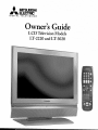
Owner's
Guide
LCD Television Models
LT-2220 and LT-3020
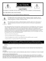
ImSKOF ELECTI>-.IC_GHOCK DO NOT OFEN
I
CAUTION:
TO REDUCE THE RISK OF ELECTRIC
NO USER SERVICEABLE
REFER
SERVICING
PARTS
INSIDE.
TO QUALIFIED
The lightning
SHOCK, DO NOT REMOVE COVER OR BACK.
SERVICE
flash with arrowhead
user of the presence of uninsulated
sufficient magnitude to constitute
PERSONNEL.
symbol within
an equilateral
triangle
is intended
"dangerous voltage" within the product's
a risk of electric shock.
to alert the
enclosure
that may be
The exclamation point within an equilateral triangle is intended to alert the user to the presence of
important operating and maintenance
(servicing) instructions in the literature accompanying
the
appliance.
Note: This equipment has been tested and found to comply with the limits for a Class B digital device, pursuant to part 15
of the FCC Rules. These limits are designed to provide reasonable protection against harmful interference in a residential
installation. This equipment generates, uses and can radiate radio frequency energy and, if not installed and used in
accordance with the instructions, may cause harmful interference to radio communications. However, there is no guarantee
that interference will not occur in a particular installation. If this equipment does cause harmful interference to radio or
television reception, which can be determined by turning the equipment off and on, the user is encouraged to try to correct
the interference by one or more of the following measures:
• Reorient
or relocate
• Increase
the separation
• Connect
the equipment
• Consult
the receiving
between
antenna.
the equipment
into an outlet on a circuit different
the dealer or an experienced
modifications
and the receiver.
radio/TV
not expressly
technician
approved
from that to which
the receiver
is connected.
for help.
by Mitsubishi
could void the user's authority
to operate this
equipment.
WARNING:
TO REDUCE
THE RISK OF FIRE
RAIN OR MOISTURE.
OR ELECTRIC
SHOCK,
DO NOT
EXPOSE
THIS
TELEVISION
TO
CAUTION:
TO PREVENT
ELECTRIC
SHOCK,
MATCH
WIDE
BLADE
OF PLUG
TO WIDE
SLOT,
FULLY
INSERT.
NOTE TO CATV SYSTEM INSTALLER:
THIS REMINDER
IS PROVIDED TO CALL THE CATV SYSTEM INSTALLER'S ATTENTION
TO ARTICLE
820-40 OF THE NEC THAT PROVIDES GUIDELINES
FOR THE PROPER GROUNDING
AND, IN PARTICULAR,
SPECIFIES THAT THE CABLE GROUND SHALL BE CONNECTED
TO THE GROUNDING
SYSTEM OF THE
BUILDING, AS CLOSE TO THE POINT OF CABLE ENTRY AS PRACTICAL.
Contents
Important
Chapter
Chapter
Chapter
Chapter
Chapter
1
Safeguards
.........................................................................
Television
4
Overview
Thank You ...................................................................................................................................
8
Unpacking Your New TV. .................................................................................................
Special Features ...............................................................................................................
Front Control Panel ..........................................................................
9
9
10
Side Pand Input/Output
......................................................................
11
Connecting an Antenna or Wall Outlet Cable .............................................................................
Connecting an Antenna to a Cable Box or VCR ...................................................................
Connecting an Antenna to a Cable Box and VCR .............................................
Connecting Audio Components to a Cable Box or VCR .......................................
Connecting an Audio Receiver ................................................................
Connecting a DVD Hayer or Other S-Video Device ...........................................
Connecting a DTV Receiver ..............................................................................................
Connecting MonitorLink _ or PC Image ......................................................
How Connections Affect the PiP and POP ....................................................
14
15
16
16
17
18
19
21
22
2
3
Connections
Remote
Control Functions
Overview of the TV Layer Buttons ..............................................................................................
Care and Operation ...........................................................................
Channel Selection ............................................................................................................
24
25
26
Sleep Timer .....................................................................................................................
Use With Other A/V Products .................................................................
26
27
Special Functions ..............................................................................................................
Operation of liP and POP ...............................................................................................
29
29
4
Menu
Screen Operations
The ViewPoint _ Menu System ......................................................................................................
MAIN Menu ................................................................................
SETUP Menu ..................................................................................................................
CAPTIONS
Menu ...........................................................................
CHANNEL
EDIT Menu .....................................................................
V-CHIP LOCK Menu ........................................................................
ADVANCED
FEATURES Menu .............................................................
32
33
35
39
41
43
46
AUDIO/VIDEO
50
5
SETTINGS
PIP/POP
Available On-Screen
Menu ...........................................................................................
Operations
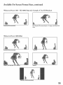
Format Sizes ........................................................................................................
.54
Operation of PiP and POP ...............................................................................................
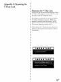
Appendix A: Bypassing the V-Chip Lock.. .....................................................
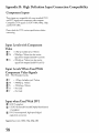
Appendix B: HD Input Connection Compatibility ............................................
Appendix C: Remote Control Programming Codes .....................................................................
Appendix D: Cleaning and Service .....................................................................................
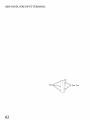
Side Pand for Input Terminal .................................................................
Index ..........................................................................................
56
57
58
59
61
62
63
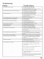
Troubleshooting ...............................................................................
Warranty.. ........................................................................................................................
65
67
3
IMPORTANT
Please
SAFEGUARDS
read the following
Always follow all warnings
1.
Read,
Retain
safeguards
for your TV
and instructions
and Follow
and retain
marked
for future
reference.
on the television.
All Instructions
Read all safety and operating instructions before operating
future reference. Follow all operating and use instructions.
the TV.
Retain
2.
Heed Warnings
Adhere to all warnings on the TV and in the operating instructions.
3.
Cleaning
the safety and operating
instructions
Unplug the TV from the wall outlet before cleaning. Do not use liquid, abrasive, or aerosol cleaners.
permanently damage the cabinet and screen. Use a lightly dampened cloth for cleaning.
4.
Attachments
and Equipment
Never add any attachments
and/or equipment without
the risk of fire, electric shock or other personal injury.
5.
Water
;.
Cleaners
as such additions
can
may result in
and Moisture
Do not use the TV where contact with or immersion
kitchen
approval of the manufacturer
for
sinks, laundry
tubs, swimming
in water is possible.
Do not use near bath tubs, wash bowls,
pools, etc.
Accessories
Do not place the TV on an unstable cart, stand, tripod, or table. The TV may fall, causing serious
injury to a child or adult and serious damage to the TV. Use only with a cart, stand, tripod, bracket,
or table recommended
by the manufacturer,
or sold with the TV. Any mounting of the TV should
follow the manufacturer's
instructions,
and should use mounting accessories recommended
by the
manufacturer.
An appliance
uneven
7.
and cart combination
surfaces may cause the appliance
should be moved with care.
and cart combination
O_ick stops, excessive force, and
to overturn.
Ventilation
Slots and openings
in the cabinet
are provided
for ventilation
and to ensure reliable operation
of the TV and to
protect it from overheating.
Do not block these openings or allow them to be obstructed by placing the TV on a bed,
sofa, rug, or other similar surface. Nor should it be placed over a radiator or heat register. If the TV is to be placed
in a rack or bookcase, ensure that there is adequate ventilation and that the manufacturer's
instructions have been
adhered to.
o
Power Source
This TV should be operated
only from the type of power source indicated
on the marking
label.
If you are not sure
of the type of power supplied to your home, consult your appliance dealer or local power company.
outlet shall be installed near the equipment and shall be easily accessible.
°
Grounding
or Polarization
This TV is equipped with a polarized
alternating
current
The socket-
line plug having one blade wider than the other.
This plug
will fit into the power outlet only one way. If you are unable to insert the plug fully into the outlet, try reversing the
plug. If the plug should still fail to fit, contact your electrician to replace your obsolete outlet. Do not defeat the
safety purpose of the polarized plug.
10. Power-Cord
Protection
Power-supply cords should be routed so that they are not likely to be walked on or pinched by items placed upon or
against them, paying particular attention to cords at plugs, convenience receptacles, and the point where they exit
from the TV.
11. Lightning
For added protection
for this TV during
a lightning
of time, unplug it from the wall outlet and disconnect
TV due to lightning
and power-line
surges.
storm, or when it is left unattended
the antenna
or cable system.
and unused
for long periods
This will prevent damage
to the
IMPORTANT
12. Power
SAFEGUARDS,
continued
Lines
An outside antenna
system should not be located in the vicinity of overhead
power circuits, or where it can fall into such power lines or circuits.
extreme
care should be taken to keep from touching
When
power lines or other electric light or
installing
an outside antenna
such power lines or circuits as contact with them
system,
might be fatal.
13. Overloading
Do not overload wall outlets and extension cords as this can result in a risk of fire or electric shock.
14. Object
and Liquid
Entry
Never push objects of any kind into this TV through openings as they may touch dangerous voltage points or shortout parts that could result in fire or electric shock. Never spill liquid of any kind on or into the TV.
15.
Outdoor
Antenna
Grounding
If an outside antenna or cable system is connected
provide
some protection
Section
810 of the National
to the TV, be sure the antenna
against voltage surges and built-up
Electric
Code, ANSI/NFPA
or cable system is grounded
No. 70-1984
provides
information
with respect to proper
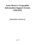
EXAMPLE OF ANTENNA
grounding of the mast and supporting structure, grounding
to an antenna discharge unit, size of grounding conductors,
so as to
static charges.
G ROL,'N D NG
of the lead in wire
location of antenna
LEAD _NWIRE
discharge
unit, connection
to grounding
electrodes,
and requirements
for the
GROUND CLAMp
grounding
16.
ANTENN A
electrode.
DISCHARGE UNIT
{NEC SECTION 810
2O)
GROUNDING
NTENNA
CONI?UCTOI?S
Servicing
Do not attempt
to service this TV yourself as opening
expose you to dangerous
voltage or other hazards.
or removing
{NEC SECTION
covers may
Refer all servicing
to qualified
service personnel.
810 21)
UND CLAM£8
NEC
NATIONAL ELECTRICAL CODE
_,POWER
$E_VtCE GRO{_NDING
ELECTRODE SYSTEM
(NEC ART 25O, PART H)
17. Damage Requiring Service
Unplug the TV from the wall outlet and refer servicing to qualified service personnel under the following conditions:
(a) When
the power-supply
cord or plug is damaged.
(b) If liquid has been spilled, or objects have fallen into the TV.
(c) If the TV has been exposed to rain or water.
(d) If the TV does not operate normally
by following
the operating
instructions,
adjust only those controls
covered by the operating instructions as an improper adjustment of other controls may result in damage
often require extensive work by a qualified technician to restore the TV to its normal operation.
(e) If the TV has been dropped
(f) When
and will
or the cabinet has been damaged.
the TV exhibits a distinct
18. Replacement
that are
change in performance
- this indicates
a need for service.
Parts
When replacement parts are required, be sure the service technician has used replacement parts specified by the
manufacturer
or have the same characteristics
as the original part. Unauthorized
substitutions may result in fire,
electric shock or other hazards.
19. Safety Check
Upon completion of any service or repair to the TV, ask the service technician to perform safety checks to determine
that the TV is in safe operating condition.
20.
Heat
The product
should be situated
away from heat sources such as radiators,
heat registers,
stoves, or other products
(including amplifiers) that produce heat. Do not place this product in an enclosed place (bookcase
proper ventilation.
Do not block the vents or openings on this product.
or wall) without
5
IMPORTANT
21. Transport
(a) Be sure to use another
SAFEGUARDS,
person to lift or carry this display.
display be used to transport
22.
LCD
the unit.
Be sure that items such as belt buckles,
watches,
shirt buttons,
and
Monitor
all panels.
Your picture
performance
of over 2.9 million thin film transistors.
It is common to find a few
Do not be alarmed. This is a result of the manufacturing
process found in
will not be affected.
Mounting
VVhen mounting this display to a wall, a UL 1678 Listed wall mounting
surface must be used.
6
that one hand on each side of the
do not scratch or rub the screen or cabinet.
This monitor uses a technology composed
colored (non-active) "dots" on the screen.
23.
It is recommended
the display.
(b) Use caution when transporting
zippers
continued
bracket suitable
for the weight and mounting
1
Side Panel Input/Output
...........................................................................................
ll
Thank
You for Your Purchase
Welcome to the wonderful and exciting world of digital television! We are honored that you chose Mitsubishi
as your premier home entertainment
partner. The development team at Mitsubishi Digital Electronics America
(MDEA) understands that our customers demand and expect the very best. MDEA was founded on the
core beliefs and philosophies that drive us to deliver products that implement the latest in advanced television
technology.
While some televisions are destined for obsolescence in the near future, MDEA's televisions are all HDupgradeable.
This cornerstone of your home entertainment
system will continue to provide unparalleled
enjoyment for years to come!
Whether this is your first Mitsubishi consumer electronics product or another addition to your growing
Mitsubishi system, we hope that this television will bring you many hours of enjoyment.
OUR
PROMISE
We will engineer and manufacture the upgrades necessary so the HD-upgradeable
television you purchased
today can be made compatible with near-future advances in digital television and digital interconnectivity.
Specifically, we promise that you will be able to have your television upgraded, at a reasonable cost, to include
an off-air HDTV tuner, a cable TV tuner (for unscrambled programming),
an IEEE 1394 (FireWire ®)
connection, HAVi system control, and 5C copy protection.
8
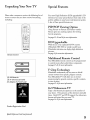
Unpacking
Your New TV
Please take a moment to review the following list of
items to ensure that you have received everything
including:
Special Features
Your new High Definition (HD) upgradeable LCD
television has many special features that make it the
perfect addition to your home entertainment
system.
A few of these special features are:
PIP/POP
Viewing Option
Using Picture-in-Picture
and Picture-outsidePicture gives you exciting options for viewing
favorite programs.
Seepages 22, 29 and 56for more information.
HD Upgradeable
With the use of an optional HDTV receiver
(Mitsubishi HD-5000 or similar model) your
Mitsubishi television can display high definition
pictures.
Remote
Seepage 21for connection information.
Control
Multibrand
Remote Control
Your Mitsubishi remote control can be programmed
to control many other audio/video components.
Seepages 27-28 for more information.
V-Chip
r2) AA
Batteries
(1) 75-ohm
ACAdapter
Coaxial
(LT-2220
Cable
only)
Technology
Mitsubishi understands you may want to shield
certain viewers from specific program content.
Your Mitsubishi TV will allow you to restrict
programming by general contents, specific contents,
or even by time.
Seepages 43-45for more information.
16:9 Widescreen
TV
Enjoy a full theatrical experience in the comfort of
your home. View pictures as film directors intended
them. Both DTV and DVD support the widescreen
format well-suited for your new TV.
See pages 54-55 for more information.
Product
Registration
Quick Reference
Card
Card (notpictured)
9
Front Control
Many
remote
panel
shown
control
below.
Panel
buttons
Please
are duplicated
see Remote
V ADJUST•
Functions,
_ J_DJUST
)*
(P0_r Indi_00
The ADJUST,
on the front control
Control
EN]I_
panel.
page
Duplicate
buttons
24, for an explanation
are shaded
of their
in the
usage.
MENU
{IRSens0r)
ENTER,
MENU,
and CANCEL
buttons may be used to access or navigate
through the screen menus
Timer
F
D
During
normal
operation,
the timer
light glows
green
when the TV is on. It does not glow when the TV is
off. When the timer is used to turn the TV on at a
TIMER
specific time, the green timer light blinks while the
TV is off. When
the PC Power Save function
is set
to On, the timer
and PC Power
light
blinks
light glows
amber.
Save are set to On,
amber.
See Timer
If both
the timer
the amber
Menu,
page
timer
47 for
timer setup instructions.
A/V Reset
AN RESET
Press
this button
the factory
Menu,
default
to reset
all A/V
settings.
memory
inputs
to
See Audio/Video
Settings
the size and shape
of the
page 50 for instructions.
CANCEL
Format
FORMAT
ENTER
10
Press
this button
main
TV
picture.
to change
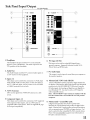
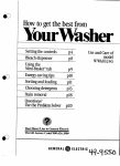
Side Panel Input/Output
TV Side Panels
_ _jmlo
MM _
_
..................
{ 2 ......................................
5
8
4
1. Headphone
PC Input
,
The Headphone Output sends the TV's connected audio
signals to a pair of headphones. The audio output from the
TV's speakers will be unavailable.
2. Audio
Out
The Audio Output sends the TV's connected
an A/V receiver or other equipment.
audio signals to
This input can be used for analog RGB signals from a
personal computer. Supported resolutions include VGA,
SVGA, XGA, and WXGA only.
7. PC Audio
,
MonitorLinkWDVI
(with HDCP)
This is a Mitsubishi-exclusive
proprietary digital interface for
the display of high quality digital video signals from Mitsubishi
products such as the HD-5000 HDTV Receiver/Controller.
All video signals, both analog and digital are sent digitally to
your Mitsubushi TV. Can also be used as a DV1 input for
other compatible sources.
Note: The DVI-HDTV
input terminal is compliant with the
EIA-861 standard and is not intended for use with personal
computers.
antennas or a cable
5. Component
Inputs 1-2
These inputs can be used for the connection of A/V equipment
with component video outputs, such as a DVD player or
compatible Video Game System. Please see Appendix B, page
58, for signal compatibility.
Input
This output is used to input the sound from your computer to
the monitor's speakers.
3. Inputs
1-2
These inputs can be used for the connection ofa VCR, Super
VHS (S-VHS) VCR, laser disc player, or other A/V device to
the TV. With each input, you may connect to the S-VIDEO
or VIDEO terminal but not to both.
4. ANT (Antenna)
ANT receives signals from VHF/UHF
system.
(60 Hz)
,
MonitorLink
"_ Control/RS-232C
A digital control interface that works in parallel with
MonitorLink.
While MonitorLink
provides the digital video
signal, MonitorLink
Control provides enhanced functioning
such as automatic power ON/OFF
also be used with other compatible
Please visit www.mitsubishi-tv.com
RS-232C command structure.
and input selection. Can
RS-232C external devices.
for more information or
11
This page intentionally left blank
12
2
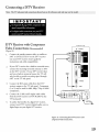
Connecting
a DTV
Connecting
MonitorLink
How
Connections
Receiver
Affect
TM
.........................................................................................
or PC Image
......................................................................
the PIP and POP
.......................................................................
19
21
22
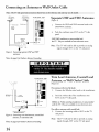
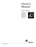
Connecting
VHF Antenna
an Antenna or Wall Outlet Cable
UHF Antenna
(Channels
2q3)
{Channels
] 4_69)
_/
_
TV side panel - right
MH*'----
FlatTwinLead
F_atTwinLead
Separate
Connect the UHF and VHF antenna leads to the
UHF/VHF combiner.
2.
Push the combiner onto ANT on the TV side
panel.
UHF/VHF combiners are not provided with
the TV. They are available at most electronic stores.
to
75 Ohm
__
Combiner
__
Note:
Back
and VHF Antennas
1.
Externa_
Antenna
or Cable
300 Ohm
UHF
(Figure 1)
This TV will only be able to provide an analog
signal through ANT on the TV side panel.
Side
[]
Figure l. Connecting separate UHF and VHF
antennas.
Note: Seepage 5for Outdoor Antenna
Grounding
TV side panel - right
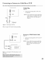
Twin Lead Antenna, Coaxial Lead
Antenna, or Wall Outlet Cable
(Figure 2)
For antenna
3OOOhm Flat
Twin Lead
75 Ohm
Coaxial Cable
with twin flat leads:
1.
Connect
the 300ohm
twin leads to the transformer.
2.
Push the 75ohm side of the transformer
onto
ANT on the TV side panel.
300ohm
°optional
300 Ohm to 75 Ohm
Matching Transformer
Figure2.
with the TV.
3.
14
Grounding
are notprovided
Connect
with coaxial lead:
the incoming
cable to ANT
on the TV
side panel.
Connecting twin lead antenna, coaxial lead
antenna, or wall outlet cable.
Seepage 5for Outdoor Antenna
transformers
They are available at most electronic stores.
For cable or antenna
Note:
Note:
to 75ohm matching
This TV will only be able to provide an analog
signal through ANT on the TV side panel.
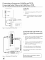
Connecting
N6_
an Antenna to a Cable Box or VCR
gB_ _neland co_ti6_
TV side panel
(section
_how_h_re al'efo_g_fe_
_ay vary
Cable Box
detail)
(Figure 3)
1.
Connect the incoming cable to ANT on the
TV side panel.
NOTE:
If your cable box has separate audio!video
outputs, please see Composite Video with
Audio or S-Video with Audio, page 16
(Figure 6).
Cable Box back panel
(section detail)
Figure 3.
Note:
Connecting
the cable box.
See page 5 for Outdoor Antenna
TV side panel (section
grounding.
detail)
Antenna
(Figure
1.
}_
--
or Wall Outlet
Cable
4)
Connect the incoming cable to ANT on the TV
side panel.
nWi11ENNA
NOTE:
VCR back panel (section
detail)
If your cable box has separate audio!video
outputs, please see Composite Video with
Audio or S-Video with Audio, page 16
(Figure 6).
Figure 4. Connecting the VCR with antennas or wall
outlet cable.
15
Connecting
an Antenna to a Cable Box and VCR,
Connecting Audio/Video to the Cable Box or VCR
_
panel and
TV side panel
(section
h h_!_
fo refere_
vary by _del
Cable Box
detail)
(Figure
1.
Connect the incoming cable to ANT on the TV
side panel.
NOTE:
Cable
Figure 5. Connecting
5)
For best performance, please see Composite
Video with Audio or S-Video with Audio,
below.
Box RearTerminals
the VCR with cable box.
Composite Video with Audio or S-
TV side panel - left
Video with Audio (Recommended)
w
(Figure 6)
.
Connect a video or an S-Video cable from VIDEO
OUT on the VCR back panel to VIDEO or
S-VIDEO, INPUT-1 or INPUT-2 on the TV side
panel.
2.
Connect a set of audio cables from AUDIO
on the VCR back panel to AUDIO
INPUT-2 on the TV side panel.
Attad
If your VCRhas avideo
channel or RFON/OFF
VCRbackpanel
{
switch,
settoOFE
INPUT-1
One
cable
type
If your VCR is mono (non-stereo), connect only the
white (left) cable.
s
16
or
• The red cable connects to the R (right) channel
• The white cable connects to the L (left) channel
v_file
Figure 6. Connecting the VCR Audio/Video.
OUT
You may connect to the S-VIDEO
terminal
but not to both.
or VIDEO
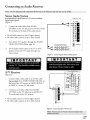
Connecting
an Audio
Receiver
Stereo Audio System
(recommended
for shelf units or A/V receivers
without
TV side pane[
digital audio inputs)
(Figure 7)
1.
Connect
R_d
[]
the audio cables from AUDIO
OUTPUT
- left
WhFte
on the TV side panel to TV IN or AUX
IN terminals
on the back of the audio
system.
• The red cable connects to the R (right) channel
• The white cable connects to the L (left) channel
2.
Turn offthe
VIDEO
3.
TV's speakers
SETTINGS
Menu,
through
the AUDIO/
page 50.
Set the audio system's input to the TV or AUX
position to hear the TV's audio through your
stereo system.
Figure Z Connectingthe
StereoAudio
A/V Receiver
(Figure
.
System.
AV Rece_wr/back
pand
_ect_o_)
[]
f
8)
Re_ Awhile
Connect either a video cable or an S-Video cable
(but not both) from VIDEO MONITOR OUT on
the back of the A!V receiver to VIDEO INPUT-1
11' _111
9@
TV _e
or INPUT- 2 on the TV side panel.
panel
_elt
9@
_ft_
H
2.
Connect a set of audio cables from AUDIO
OUTPUT on the TV side panel to AUDIO
IN on the back of the A/V receiver.
A_tad_
TV
cab_
type
• The red cable connects to the R (right) channel
• The white cable connects to the L (left) channel
Figure&
ConnectingtheA/VReceiver.
17
Connecting
a DVD Player or Other S-Video Device
DVD Player/Video
[]
Component
f
(Figure
.
1V _de pand.
fight
DVD back
Figure 9. Connecting
panel
a DVD Player with Component
iMPORTANT
2.
Video.
Game with
Video
9)
Connect the Component Video cables from
(YCbCr or YPbPr) VIDEO OUT on the back of
the DVD player to COMPONENT
(1 or 2) on
the TV side panel. The correct connections are:
A. YtoY
B. Cb or Pb to Pb
C. Cr or Pr to Pr
Connect a set of audio cables from AUDIO OUT
on the back of the DVD player to COMPONENT
AUDIO Input (1 or 2) on the TV side panel.
• The red cable connects to the R (right)channel
• The white cable connects to the L (left) channel
NOTE:
Some video game systems support component
connections. Please refer to your video game
console Owner's Guide.
NOTE:
If your DVD player supports progressive
scan playback, be sure to set your player
accordingly. Please refer to your DVD player's
Owner's Guide.
Other S-Video Device
(Figure
[]
1.
10)
Connect
an S-Video
cable from VIDEO
on the device back panel to VIDEO
INPUT-2
2.
Connect
Amy S-Video
•
Device
i
wh_t,,
J
Figure lO. Connecting an S-Video Device.
18
INPUT-1
or
on the TV side panel.
a set of audio
cables from AUDIO
on the device back panel to AUDIO
INPUT-2
OUT
OUT
INPUT-1
or
on the TV side panel.
• The red cable connects to the R (right) channel
• The white cable connects to the L (left) channel
If your S-Video Device is mono (non-stereo), connect
only the white (left) cable.
Connecting
_!
h_ _
!d _!
a DTV Receiver
and _n_
!_wn
_!_ fo! re fere_
_
_
_
ar
b_ _d_
DTV Receiver with Component
Video Connections (Recommended)
TV Side Panel - right
(Figure 11)
Connect the outside antenna cable, or satellite to
ANT or SATELLITE IN on the DTV receiver
.
(see your DTV receiver owner's guide for
instructions and cable compatibility).
.
If your DTV receiver has a built-in terrestrial tuner,
connect the incoming terrestrial antenna to ANT
on the DTV receiver. If your DTV receiver does
not have a built-in terrestrial tuner, this TV will
Encom_n9
A_t_nna_
only be able to provide an analog signal through
ANT on the TV side panel.
3.
4.
Connect the RCA-type cables from the DTV
receiver outputs to the TV side panel. Component
(1 or 2) may be used for 480i, 480p, 720p or 1080i
components.
DTV Receiver (with con
_onent
video
connections)
Connect the L (left) and R (right) audio cables
from the DTV receiver to DTVAUDIO
on the
TV ba& panel.
5.
U_ ..........
To utilize the benefits of a digital A!V receiver,
connect your DTV receiver's digital audio out to a
digital input on your digital A/V receiver.
Figure ll.
component
Connecting the DTVreceiver
Video Connections.
with
19
This page intentionally left blank
20
MonitorLink
TV side panel - right
(Figure 14)
1. Connect
a MonitorLink/DV1
panel to the Mitsubishi
panel.
Connect
2.
the MonitorLink
cable from the TV side
HD Receiver/Controller
Control/RS-232
the TV side panel to the Mitsubishi
Controller back panel.
iI
back
cable from
HD Receiver/
r0
o.
.
Connect the L (left) and R (right) audio cables from
the HDTV receiver to AUDIO LEFT and AUDIO
RIGHT on the MonitorLink section of the TV side
[]
arl
panel.
NOTE:
The 29-pin MonitorLink/DVI
and 9-pin
RS-232 cables can be found at your local electronics
store. Please refer to www.mitsubishi-tv.com
for more
information
on RS-232C
CAUTION:
the user must
with bonded
control.
To assure continued
use a shidded video
ferrite
MonitorLink/DVI
FCC compliance,
interface
cable
cores at each end, when
input.
using the
Figure 15. Connecting Computer
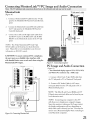
PC Image and Audio Connection
(Figure 15)
• Your Mitsubishi
display supports VGA, SVGA, XGA,
and WXGA
PC resolutions only.
(60Hz
only)
1. Connect
a Mini D-sub 15-pin (RGB) cable from
the TV side panel to PC or Macintosh * back panel.
[]
2. Connect
a PC Audio Cable (or 1/8" stereo
mini jack cable) from the TV side panel to PC or
Macintosh
MRsubishtHDS000recelver/controllerbackpa_el
NOTE:
back panel.
The Mini D-sub
15-pin (RGB) and 1/8"
(3.Smm) stereo mini jack cables can be found at your
local electronics store.
NOTE:
Connecting
your computer
to this TV
will allow you to display your computer's
Since this monitor
is widescreen
images.
(16:9 aspect ratio),
the display configuration
will vary depending on
which video card or driver(s) you use. You may also
need to use a Macintosh
Figure l4. Connecting MonitorLink
some Macintosh
adapter when connecting
to
computers.
21
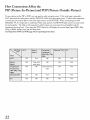
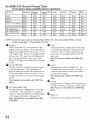
How Connections
Affect the
PIP (Picture-In-Picture)
and POP (Picture-Outside-Picture)
To see a picture in the PIP or POP, you may need to select an input source. If the only input connected is
ANT, then both the main picture and the PIP/POP will be from that input source. If other video equipment
is connected, you may be able to view these input sources as the PIP/POP.
When connecting your new
Mitsubishi TV, it is important to understand which main picture and PIP/POP
input sources can and cannot
be used together. The table on this page shows which inputs can and cannot be used together and the
limitations they may have. If you press the INFO button it will display the current Input signal (480i, 480p,
720p, or 1080i), format, time, day and sleep time.
See Operation of PIP and POP, page 56, for operating instructions.
OK
N/A
OK
OK
N/A
OK
Only with
OK
OK
N/A
OK
same input
OK
Only with same
OK
N/A
input
22
OK
OK
N/A
OK
N/A
OK
OK
OK
OK
N/A
Remote Control
Functions:
Overview of the TV Layer Buttons
Overview
(Figure
1, following
page)
Slide Switch: Select A/V product to be controlled by
the remote control.
POWER:
connected
Turns power on and off for TV and other
A/V products.
Numbers: Individually
information into TV.
select channels
or input
GUIDE:
When
VIDEO:
Select the individual video settings.
PIP/POP:
choices.
the slide switch is set to CABLE/
program guide
receivers).
DEVICE:
Select the input to view; ANT,
Component-i,
Component-2,
Input-l, Input-2,
MonLink, or PC.
CH (channel): Scroll up or down through memorized
channels. Skips DVD chapters in DVD layer.
VOL (volume): Change
sound level.
audio settings.
Cycle through
PIP and POP display
Display _E
EXCH:
picture.
Exchange
SLEEP:
Set the TV to turn offwithin
Sleep Timer,
®on-screen
menu
FORMAT:
TV picture.
2 hours.
See
Select the PIP or POP input source.
Change
CONNECT:
the shape and size of the main
No current function.
Manually
REW/REV:
VCR,
system.
PIP or POP with the main TV
page 26, for setup instructions.
PIP DEVICE:
REC:
DVD.
Turn sound on or off.
TV MENU:
Select the individual
ViewTM): Switch to last channel viewed.
DBS/DTV,
display the on-screen
(some cable boxes and DBS/DTV
MUTE:
AUDIO:
PIP CH: Scroll up or down through memorized
channels in PIP or POP.
SQV (Super O_ick ViewTM): Scan through a
memorized list of favorite channels.
O_V(O_ick
INFO: Display on-screen summary of the current
input used and any broadcast information available
(including current V-Chip information, Signal Source
and Format). Additionally, if you press the INFO key,
it will display time, day and sleep time.
record
Rewind
with your VCR
or reverse search
reverse scan with your DVD,
or recordable
with your
or skip reverse
with your CD.
DEVICE MENU:
A/V device.
Display menu for a connected
PLAY: Play your VCR, DVD, or CD.
ADJUST: Navigate menus, change settings,
the PIP on-screen location.
ENT (enter): Select a channel number
HOME:
Exit on-screen
and move
or menu item.
menus and return to TV
viewing.
CANCEL:
Clear SQV and some menu entries. Used
as a subchannel button in Cable/DBS/DTV
layer.
V-CHIP: Displays V-Chip Passcode screen, use to
enable or disable the V-Chip Lock.
24
STOP: Stop your VCR, DVD, or CD.
FF/FWD:
Fast forward
your VCR,
forward
or forward
fast play with your DVD,
with
search
with
or skip
your CD.
PAUSE: Pause your VCR, DVD, AV Disc, or freeze
the PIP or POP image.
Remote
Control
Functions:
Care and Operation
"1
Operation
Installing
(Figure
"-7-x
C¢_tSJDBSa_W
the Batteries:
VCR DVD
2)
1. Remove
the remote
control's
pressing
the ridged
tab in the direction
and sliding
q) q) _0 O
q) q) q)
q0 q) _) oo,=
back cover by gently
of the arrow
off the cover.
jj j
2. Load the batteries, making sure the polarities (+)
and (-) are correct.
For ease of installation,
install
the negative
For Best Results
Be within
(-) side first.
from
the Remote
v<Z2
Control:
c..a
..... _
20 feet of the equipment.
g
Do not press two or more buttons at the same time
unless instructed to.
c._a
.....
o
_pD:v_c
FOq_a_T
_
c...-J O
CO_C_
PAUS_ (_
Do not allow to get wet or become heated.
Avoid dropping on hard surfaces.
_
MITSiJBISHI
Do not use harsh chemicals to clean. Use only a
soft, lightly moistened cloth.
Figure 1. Remote Control Functions.
Do not mix new and old batteries.
Do not heat, take apart, or throw batteries into fire.
sizeAA
batteries
Use only AA batteries.
Operating
the Remote
Control:
You can use the remote to control the TV, CABLE/
DBS/DTV,
VCR, DVD, and AUDIO products.
Select the product you want to control by moving the
dide switch to the appropriate position. The remote
control has been preset to operate the TV and other
Mitsubishi products. To program the remote control
to operate other products, see Use of the Remote
Control with Other A/V Products, page 27.
v
!
Figure 2. Installing
@@
the batteries.
25
Remote
Control
Functions:
Channel
Selection,
Channel
Sleep Timer
Selection
Enter three numbers ( ex. for channel 2, press 002).
or
_. Press the channel number and ENT (ex. for
channel 2, press 2, then ENT).
or
_. Enter the channel number and wait four seconds
(without pressing ENT). The TV will change
automatically.
Sleep Timer
PIP CH
PIP/POP
EXCH
SLEEP
(Figures 3 & 4)
Setting the Sleep Timer:
Press SLEEP on the remote control.
PiP DEVICE
FORMAT
CONNECT
C)
A message indicating the length of time the sleep
timer is to be set appears on the TV screen.
j
Figure 3. Sleep button on remote control
Sleep: 30 min.
Each press of SLEEP will increase the time
displayed by 30 minutes, until the maximum
of 120 minutes is reached.
value
_. After 5 seconds of inactivity, the message will
disappear.
Press SLEEP to view the remaining time before the
timer turns the TV off.
Canceling
the Sleep Timer:
Press the SLEEP button to display the on-screen
message.
Figure 4. On-screen display for sleep timer
26
Press SLEEP repeatedly until OFF is displayed.
After 5 seconds of inactivity, the message will
disappear.
Use of the Remote Control with Other A/V Products
CABLE/DBS/DT_
VCR DVD
TV-o
_ _, _ t-AUDIO
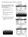
Programming the Remote Control
to Use with Other Brands of Audio
and Video Products:
1. (
Move the slide switch at the top of the remote to
the product you want to control.
2.
Press and hold the POWER
control.
3.
Enter the first three digit code listed for your
equipment, and then release the POWER button
on the remote control.
Cable box brand
General Instruments/
Jerrold
Motorola
Oak
Pioneer
Scientific Atlanta
I I
") )
Code_enten
119,120,121,122,123,
124
125,126,127
139,137,102
101,116
112,113
117,100
Zenith
button on the remote
4. Point the remote control to the equipment
press the POWER button.
II
m
1
(Figures 1-3 this page, figures 4-5 following page)
1.
I
(
Ifyour
cable box
code is not
listed here,
please see
page 59
for a
complete
listing.
To reset to default code, enter 000
Figure 1. Programming
cable
box.
the remote to control your
and
Note: If the equipment responds, the remote control is
properly programmed to operate the equipment. If
the equipment does not respond, repeat steps 2-4
with the next three digit code listed in step 3 for
your equipment.
CABLE/DBS/DT_
VCR DVD
TV,,,, "1 ,l, ,_ ,,-AUDIO
_
i
1._ (
mil
I
[u]
.
) )
1
Satellite brand
Codeto enter:,
006
175
173
174
176
177
Mitsubishi DTV - DBS
DishNetwork
Hughes - DBS
Panasonic - DBS
RCA - DBS
Sony - DBS
Toshiba-DBS
170, 173, 189, 190, 191
If your
satellite
receiver
code is not
listed here,
please see
page 60 for
a complete
listing.
To reset to default code, enter 000
Figure2.
Programming the remote to control your
satellite receiver.
CABLE/DBS/DTV_ VCR DVD
TV-o
_ J, _ _-AUDIO
1. (
c
I
IIII
m
))
1
VCR brand
Mitsubishi
Hitachi
JVC
Philips / Magnavox
Panasonic
RCA
Sony
Toshiba
Codetoente_
001,002
020,043,065
030,054
043,044,051
041,042,043
020,053,065
048,049,050
021
If your
VCR
code is not
listed here,
3Iease see
page 60
fora
complete
listing.
To reset to default code, enter 000
Figure 3. Programming
VCR.
the remote to control your
27
Use of the Remote Control with Other A/V Products
CABLE/DBS/DTV_ VCR DVD
TV-o
_ _ _ e-AUDIO
1.(
I
II
3.1
I I
ID1vj
ml_-
2.
_
DVD/LDP brand
MRsubishi
JVC
Panasonic
Codetoente_
OO3
257
250
Philips
Pioneer DVD
258,253,272
252
261
254
253
Samsung
Sony
Toshiba
/_
If your
DVD
code is not
listed here,
please see
page 59
fora
complete
listing.
After entering the correct codes in each position of the
remote control, use the dide switch to select which
product will respond when an operational button is
pressed. If you enter a code from the AUDIO chart
while the slide switch is set to TV, the volume and
mute functions change to match the A/V receiver.
This is useful when using an A/V receiver with the
TV all the time. In all other cases, only one of the
below devices is allowed for each slide switch position.
To reset to default code, enter 000
Figure 4. Programming the remote to control your
DVD or LDP.
TV position:
[] TV
[]
Cable/DBS/DTV
position:
[] Cable box
[] Satellite receiver
[] DTV receiver
CABLE/DBS!DTV_ VCR DVD
TV-o J, /* _ o-AUDIO
I
I I I I
1. (
(
A/V receiver (volume and mute only)
m
8
Audio brand
Codetoenter:
Mitsubishi AN receiver 010, 015, 011,012,
3rid/or CD player
013, 014
234,235,236,245,
Denon
246.359
Harman Kerdon
215, 223, 242
JVC
233,232
Kenwood
208.200
Marantz
224,350
9nkyo
209, 214, 240, 247
Pioneer
205,207
Sony
222,249
Technics
218,219,221
Yamaha
202.201.243.244
i_your
audio
code is not
listed here,
please see
page 59
for a
complete
listing.
To reset to default code, enter 000
Figure 5. Programming
A/V receiver.
the remote to control your
VCR position:
[] VCR
DVD position:
[] DVD
[] LD Player
Audio position:
[] A!V receiver
[]
Mitsubishi CD player
If you have a Mitsubishi A/V receiver, the audio position
may be used in conjunction with select Mitsubishi CD
players'. Your audio position must beprogrammed to
either 010 or OIL Plug the CD player power cord into a
switched outlet on the back of your A/V receiver. Pressing
the POWER button turns On the A/V receiver, along
with the CDplayer. In the audio position, for some
CD players, the transport controls (FF, Play, Rew, etc.)
operate the CD player.
|MP@RTANT
28
Remote
Control
Functions:
Special Functions
When your remote control has been Programmed to operate another manufacturer's
performed on each layer may vary. The most common functions are:
oMitsubishi
VCRs will be com
o POWER
oCHANNEL
up/down
• 0-9 Number
Buttons
• ENTER
•CANCEL
(on some models)
oPOWER
oDirect
with additional
Selection
Buttons
• 0-9 Number
Buttons
3n some
Remote Control
(on some models)
(on some models)
oADJUST
up/down/left/right
(on some models)
• GUIDE (on some models)
• MUTE
-use number
Functions:
the function
buttons
*VOLUME
Input
product,
buttons,
SQV, and QV (on some models)
(on some
Operation
Picture-In-Picture
(PIP) and Picture-OutsidePicture (POP) features allow you to view
Programming
in different ways. While watching
the main screen, you can display programs from
other channels and other inputs. To see which
inputs can and cannot be used together, see How
Connections Affect the PIP and POP, page 22. You
can display large and small PIPs, or one POR
of PIP and POP
Activating the PIP and POP
Press PIWPOP to choose a display format. Each
time the PIWPOP button is pressed on the TV
remote control (within 3 seconds of each other),
the PIP/POP
cycles through the following display
options.
1. POP:
one POP
2. PIP:
3. PIP:
large PIP
small PiP
To turn PIWPOP Off, wait at least 10 seconds,
and press PIWPOR
The next time you activate
PIWPOP, the last used PIWPOP format will be
displayed first.
29
This page intentionally
30
left blank
4
V-CHIP
LOCK
ADVANCED
AUDIO/VIDEO
Menu ...................................................................................................
FEATURES
SETTINGS
Menu
................................................................................
Menu
...........................................................................
43
46
50
wpoimMenu System
Your TV has Mitsubishi s exclusive _
The
information
on-screen
operating
system, which provides on-screen
for menu choices and changes.
A picture (icon) will be highlighted and
can be selected using the remote control's
ADJUST arrows. When selected, the
appropiate menu will appear or start an automatic
function. You may then make changes within the
menu or access available sub-menus.
A highlighted square button indicates that you
may make changes to the menu screen.
The _R
®system includes the following
special features:
[] The currently selected icon or button is
highlighted with a rectangular yellow outline and
the text color will be yellow.
[] On-screen instructions provide complete menu
choice information.
[] Some on-screen menu options must be set before
other options are available. For example, "Timer
Menu" will only be possible if "Clock Time" and
"Set Day"have been set.
The following remote control buttons will help you
move quickly through the _]_]1[" system (Figure 2):
Figure 1. MAINmenu:
The first screen that appears when you press the
MENU
button from your remote.
TV MENU
ADJUST A or • to select the menu item you want to
change.
ADJUST • to move to the setting field.
ADJUST A or • to change the settings.
ADJUST 4 to move back to the menu item.
ENT to enter into a menu, start an automatic
function, or select a checkbox.
CANCEL
function.
to clear a setting, or stop an automatic
MENU
to move back one menu screen at a time.
HOME
to exit all menus at once and return to TV
viewing.
32
Figure2.
Thesebuttonsonyourremote
control are used for navigation within
on-screen operating system.
the
Main Menu Screens: Overview
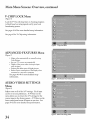
SETUP
(Figure
Menu
3)
Basic (initial) setup instructions and functions are
available through the SETUP submenu screens.
• Memorize channels,
• Assign Input Assignments
• Set the time and day
• Select English or Spanish for the menus
or screen display
• Set the Front Button Lock
Figure&
Use the setup menu when you relocate the TV,
experience a power loss or when devices are added
after initial setup. See pages 35-38 for more detailed
setup information.
SETUPMenu
CAPTIONS
(Figure
Menu
4)
Display broadcasted captions or text on the screen.
Select the closed caption setting by choosing to
display the background color as either black or
translucent gray. See pages 39-40 for more detailed
setup information.
Figure 4. CAPTIONS
Menu
CHANNEL
EDIT
Menu
(Figure 5)
• Customize the channel information
for ANT
• Manually add or delete channels from memory
• Name channels for ANT
• Add your favorite channels to a SQV (Super
Quick View "_) list.
See pages 41-42 for more detailed setup information.
Figure 5. CHANNEL
EDIT
Menu (Antenna)
33
Main Menu Screens: Overview,
V-CHIP
continued
LOCK Menu
(Figure 6)
Lock the TV by selecting times or choosing programs
to block based on rating signals sent by your local
broadcasting system.
See pages 43-45 for more detailed
See page 43 for V-Chip
ADVANCED
(Figure
setup information.
rating information.
FEATURES
Menu
7)
• Adjust colors automatically
Color Balance
or manually,
using
• Set your TV to turn on automatically
• Display a blue screen when viewing an input
with no signal
• Enhance the darker parts of bright pictures
• Reduce Power consumption of the display when
connected to a non-active computer
See pages 46-49
for more detailed
setup
information.
Figure 7. ADVANCED FEATURES Menu
AUDIO/VIDEO
SETTINGS
Menu
(Figure 8)
Adjust some or all of the A/V settings. Each input
can be set to your preferences. A/V Reset on the
menu allows you to return the A/V settings for the
current input to the factory presets. A/V Reset on the
front control panel resets all inputs at one time. See
pages 50-52 for more detailed setup information.
Figure8. Audio/Video SettingsMenu
34
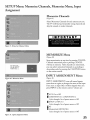
SETUP Menu: Memorize
Assignment
Channels,
Memorize
Memorize
(Figure
Menu, Input
Channels
9)
Select Memorize Channels for each antenna you use.
The TV will find and remember strong channels and
skip the unused or weaker channels.
_7_Y2
Figure 9. Memorize
Channels Menu
MEMORIZE
(Figure
Menu
10)
Stop memorization
Channels
N_
m_morizing
all
th_
stations
you
can
receive
on,_lTAir.
Please
stand
at any time by pressing
memorized
will stay in memory.
prior to pressing
After
you may select memorized
by.
descending
order by pressing
on the remote control.
INPUT
Figure 10. Memorize
(Figure
Menu
channels
channels
CANCEL.
CANCEL
are memorized,
in ascending
the CHANNEL
ASSIGNMENT
or
button
Menu
11)
INPUT ASSIGNMENT
turns offunused inputs,
turns them on again or changes the name of the input.
If you turn an input Off, it will be skipped when you
press INPUT on the remote control. Choices are:
ANT:
On or Off
COMPONENT-I,
Cycle through
INPUT-l,
COMPONENT-2
a list of preset names
or Off
INPUT-2
Cycle through
a list of preset names
or Off
Pc
MonitorLink
Cycle through
Figure 11. InDutAssignment
(MONLINK)
a list of preset names
or Off
Menu
35
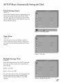
SETUP
Menu: Manually
Setting the Clock
Clock Setting
(Figure
(Manual)
12)
The Clock Setting menu default allows the clock time
to be set manually. To set the clock automatically,
please see page 37.
To set the clock manually,
including AM or PM.
first select the current time,
Press • or • to slowly adjust the time. Press and
hold • or • to quickly adjust the time.
Set Day
(Figure
13)
After manually
current day.
Figure l3. Set Day
36
selecting the current time, select the
SETUP
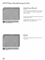
Menu: Automatically
Setting the Clock
Clock Setting (Auto)
(Figure
14)
Set the Clock Setting to Auto to automatically set the
day and time using Extended Data Service (XDS)
time data. This data is automatically retrieved when
tuned to a PBS channel or other channel in your area
that provides this service.
Time
Zone
(Figure
15)
Select
the correct
Central,
time zone
Mountain,
your area when
Auto
Pacific,
(Atlantic,
Alaska,
Eastern,
or Hawaii)
has been selected
for
as the Clock
Setting.
Figure 15. Time Zone
Daylight
(Figure
Select
Savings Time
16)
the Daylight
your state uses when
Clock
Time
(DST)
Auto
has been
option
selected
that
for the
Setting.
Applies
Ignore
The
Savings
= uses DST
= does not use DST
clock time and day will be set automatically
tuning
to a channel
Service
(XDS)
channel).
carrying
time data
the Extended
(usually
after
Data
your local PBS
Figure 16. Daylight
Savings Time
37
SETUP
Menu: Language,
Front Button Lock
Language
(Figure 17)
Display the on-screen menus in either English or
Spanish (Espafiol). The first time you powered On
your TV, you were requested to select an on-screen
menu language. If you choose to change the selection,
all menu text will immediately switch to the language
of your choice.
Figure 1Z Language /Idioma
Front
Button
Lock
(Figure 18)
Disable controls on the front panel to prevent anyone
from accidentally changing settings.
Select On to lock out the operations of the front panel
button and select Off to restore the operations of the
front panel buttons.
Figure l& Front Button Lock
38
If the front panel buttons have been locked and you
misplace the remote control, you can restore the
function of the front panel buttons by pressing and
holding the MENU button on the front panel for
more than 8 seconds. If the TV is already on, a
message will be displayed to confirm the release of the
Front Button Lock.
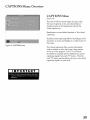
CAPTIONS
Menu: Overview
CAPTIONS
Menu
(Figure 19)
Turn On or Off the closed caption decoder, select
the type of captions or text, and choose black or
translucent gray as the background color for the
closed caption area.
Broadcasters
can send either Standard
or Text closed
captioning.
Standard closed captioning follows the dialogue of the
characters on-screen and displays in a small section of
the screen.
Figure 19. CAPTIONS
menu
Text closed captioning often contains information
such as weather or news and covers a large portion
of the on-screen program. Your TV can decode
four different standard and four different text closed
captioning signals from each TV station. However,
each TV station may broadcast only one or two closed
captioning signals, or none at all.
39
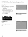
CAPTIONS
Menu: Closed Captions, Background
Closed Captions
(Figure 20)
Display one of the following
types of Closed Captions:
CC1, CC2, CC3, or CC4: Standard closed
captioning signals.
_. Textl, Text2, Text3, or Text4: Text dosed
captioning signals.
_. On if mute: Closed captions when mute. When
selected, the standard dosed captioning signal
(CC1) will turn on/offby pressing the MUTE
button on the TV remote control.
_. Off: No dosed captions.
Figure20.
ClosedCaptions
Figure21.
CCBackground
CC Background
(Figure 21)
Display the background color as either black or
translucent gray, to make the closed captions easier to
read.
40
Color
CHANNEL
EDIT
Menu: Channel,
Memory,
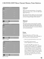
Name Selection
Channel
(Figure 22)
Select to edit the channel selections.
You can add or
delete from memory, name, or add to the SQ_V (Super
Qgick View TM) list.
After selecting Channel, editing can be done using the
Adjust buttons or entering the 3 digit channel number
you want to change (Example 002 for channel 2).
Memory
(Figure 23)
Figure22.
Cbannd
Add weaker channels
viewed with ANT
and delete
unwanted channels, after all available channels have
been memorized with Memorize Channels (page 35).
Use the CH (channel) button on the remote control to
view memorized channels.
Name
(Figure 24)
Name
channels
shown
on ANT
(up to four
characters).
After you enter a name, it will appear
the TV screen next to the channel number.
Figure 23. Memory
1. Select the memorized
on
channel you want to name.
2. Press ADJUST until you see the
underline highlighted in the Name field.
3. Use ADJUST • or • to select letters A-Z,
numbers 0-9, and!or symbols (!.&'!:*- and blank)
for each character of the name you would like for
the selected channel. Press ENT after choosing
each letter and after the name is complete. If you
want to change your selection while on the option
field, use CANCEL to delete the current character.
You will move one position back. If you press
CANCEL while at the first character, the entire
name will be deleted.
Figure24.
Name
41
CHANNEL
EDIT
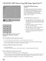
Menu: Using SQV (Super O ick
Using The Menu
(Figure
Screen
25)
Put together
ANT
View TM)
a list of your favorite
using
SQV
(Super
Quick
channels
View).
to 6 channels
in each of the 9 different
banks.
adding
After
a channel
memory, "SQV" will appear
number on the TV screen.
To change
SQV
choices
Store up
memory
to the SQV
under
using
from
the channel
the menu:
1. Press A or • when at Channel settings or use the
CHANNEL
button on the remote control to select
Figure2S.SQV(SuperQuickVm. '_')
the channel you wish to add or delete from a SQV
memory bank.
2. Press _ when at SQV in the menu to move the
selector to the On!Off setting.
3. Press • or • when at SQV setting to select the
SQV memory bank you wish to modify.
4. Dess ENT to add (On) or delete (Off) the current
channel from the SQV memory bank that you
have selected.
Figure 26. SQV (Super Quick Vieva rM) button on the remote control
Using The Remote
(Figure
Control
26)
View and add SQV channels
using the remote control:
1. Use the CH (channel) or number buttons to select the channel you want to add.
2. Press and hold the SQV button for about 3 seconds. When "SQV" and the memory bank number appear
under the channel number, the channel has successfully been added.
To change the SQV banks using the remote control:
1. Press the SQV button.
2. To change memory banks, press a number button within 5 seconds of pressing the SQV button.
Remove SQV channels
using the remote control:
1. Press the SQV button repeatedly until you see the desired channel.
2. While the channel number and SQV indicator am still displayed on the screen, press the CANCEL button.
the CANCEL button is not pressed before the SQV indicator disappears, the channel will not be removed.
3. When the SQV indicator disappears, the channel has successfully been removed.
42
If
V-CHIP
LOCK Menu: Overview
V-Chip Signal Information
When provided by the broadcaster,
When
V-Chip
ratings
the remote control.
when you change
the channel
blocking by content categvries.
Movie ratings use MPAA ratings
TV-MA
Content
Used in
FV
D
L
S
V
button
on
and movies developed _br TV and
for movies released in theaters.
EXCEPTIONS:
TV Ratings:
Used with TV programs arid Made-fb>TV movies.
TV2Y
Ybuth, fbr children ui_der the age of Z
TV_Y7
Youth, 7 years dd a_d older. _br childre_i 7 years old a_d older.
TV_G
Ge_eral Audience. t_br file entire l_mily to view.
TV-PG
Pa_ntal Guidance. Parental Guidarme is reeomme_ded, may not be
suitable for some dfildren.
TV-14
can be viewed or will be blocked.
or when you press the INFO
Both TV and Movie ratings will displ@'. TV ratings app b, to programs
m@" ha_e supplemental
V-CHIP
V-Chip ratings can be used to control which programs
are sent, you will see the ratings
Addeseent t4 years dd arid older. Not reeomme_ded lbr children
under the age of 14.
Mature Audie_me. i%r adults o_fly:
TgRating
FY
D
L
S
g
TF-PG
X
X
X
X
TF-14
X
X
X
X
X
X
X
TF-Y
TV-Y7
TV-MA
X
Categories:
associatiori with the TV ratings above.
F'a_itasyViole_me- applies m TVg.Y7 only;
Sexual Dia!og- applies i_i dil_bre_t degrees m TVaPG a_id TVq4.
Aduk Language-applies in dift_rent degrees to TVaPG, TV-14, and TV-MA.
Sexual Situatio_is- a_plies i_i dilt?re_t degrees m TV:-PG, TV-14, and TV-MA
Violence (graphic or r_alistic)- applies in differem dc_re_ to TV_PG, T_14, and TV_MA.
When you select a TV rating, you are selecting the least-restrleed program level tl_tt can be viewed, As an example, if you select
TV-PG, you are allowing programs rated TV-Y, T V-Y7, TV-G and T¥_PG to be seen and blocking programs rated TVq4 and
TV-MA, \_ghen you select a TV Content category, you will block allTV programs that t,ave the same content category listing° As
an example, if you select to block V (Violence) at the T¥_14 level, you will also block any progntm that has the V category listing at
the TV-PG nttlng level as well.
Mos4e Ratings:
Used with theater
released
movies and direct-m-video
movies.
G
PG
Oe_eral Audie_meParental Guidance-
PGq3
R
NCa17
Parental Guidance 13 years old and older- Not recomme_Med for children u_Mer the age of 13.
RestrictedRestricted in the theater to 17 years old a_d older u_fless accor_panied
by' an adult.
No ChildrenRestricted i_ the theater to t8 years old and alder.
X
Adult-
Designed
Designed fbr the e_tire f;amily to view.
Pa_ntal
G uida_me is reeomme_Med,
m%v _mt be suitable
lbr a_d restricted
i_ the theater
to adult
for some dfildren.
audie_mes o_fiy;
V_rhen you select a Movie rating, you are selecting the least restricted
progntm level that can be viewed, As an example, if you select
a movae.... nttmg of PG-13 you are allowing mo* .....
ies rated O PG and PG 13 to be seen and blocking mo* ies rated R NC 17, and X
Programs Not Rated: Used tbr programs that are not
rated like news, sports, weather, emergent T bulletins,
or movies such a_sthose prior m or without MPAA
Ratings. This does not include progra_r_s withouz VCt_p signals.
43
V-CHIP
Menu: Setting Up and Using V-Chip Lock Passcode
Setting Up the V-CHIP
Passcode
LOCK
(Figure 27)
Select V-CHIP
LOCK
from the MAIN
menu
for first time setup or at}er you have canceled your
passcode. You will see the screen shown in Figure
27. Use the number buttons on the remote control to
input a new ibur-digit
Figure 2Z First time entry to the V-CHIP
LOCK
p_sscode, then press ENT.
Before pressirg EN'I. you can delete a characxer aM
move back one character by pressing CANCEL,
or
Ieave the pKsscode screen by pressing MENU or
HOME.
Entering the Passcode
(Figure 28)
Input your passcode as shown in Figure 28 (Note:
Text changes from "a new" to "your" passcode) the
next time you select V-CHIP LOCK from the
MAIN menu, you will see this screen.
iMPORTANT
Figure 28. Re-enPry
44
to the V- CItlP
LOCK
V-CHIP Menu: Allowing or Blocking Ratings, Locking by
Hour or Time
Allowing or Blocking by Ratings
(t:'igure 29)
Block or Allow programs based upon rating signals
sent by the broadcasting station. The facto_ preset
for TV Ratings is TV-PG (Parental Guktance)
allowing only programs rated TV-PG or lower. The
t_cto_ preset for Movies is PG, allowing only movies
rated PG or lower. Please refer to page 43 for a
detailed ratings description.
V-CHIP
HOURS
/ LOCK BY TIME
Figure 29.
V-CItlPLOCK
Choices
(Figure 30)
V-CHIP HOURS /LOCK BY TIME will allow you
to activate the V-Chip or lock the entire TV durir N
spedilc hours.
V-CHIP
Time
(Figure
Start Time and V-CHIP
Stop
30)
Select the times you wouId like the V-Chip to be
Active. By settir g the V-Chip Start Time and VChip Stop Time to the same time, the V-Chip will be
acfive 24 hours a day.
Press A or • to slowIy adjust the time.
hold A or • to quickly adjust the time.
Press and
Figure 30. V-CHIP
HOURSiLOCK
BY TIIVIE
Lock by Time, Lock Time, and Unlock
Time
(Figure 30)
Lock by Time locks the entire TV when Lock by
Time is On and you have selected a Lock Time and
Unlock Time. Your TV continues to be locked until
you input your p_sscode, or when the locked time
expires.
45
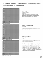
ADVANCED
FEATURES
Menu: Color Balance, Auto Color
Correction, ColorView TM,Reset Color
Color Balance Menu
(Figure 31)
Your Mitsubishi TV uses _x colors (Magenta, Red,
Yellow, Green, Cyan and Blue) to create Color
Balance. You may adjust these colors automatically or
manually or reset them to the defauIt settings.
Auto Color Correction
(Figure 32)
Figure 31, ADVANCED
FEATURES
MENU
Set the Auto Color Correction option to On
to optimize skin tone color aummatically and
confmuou@
Both Manual Color Adjustment and
Reset Color options are grayed out and unavailable
when On is selected tbr Auto Color Correction.
Reset Color
(Figure 32)
Select to reset the ColorView
settings.
• Each active input can be individually
reset.
ColorView
(Figure
Figure32,
COLOR
BALANCE
1_€lenu
33)
Press ENT to display the menu to manually adjust
the tint of each color. Individual diders for Magenta,
Red, Yellow, Green, Cyan and Blue will be displayed.
The sliders have a numeric value, where 63 is the
maximum. The defauIt setting for each color is 31
(center). Highlighted text will show which slider you
are adjusting.
• Each active input can be individually
adjusted.
Press Adjust • or • to navigate between colors and
Adjust _ or _ to change the color slider settings.
Figure 33. CMorView Menu
46
The ColorView option is only available when Auto
Color Correction b turned OtE
ADVANCED
Set Time
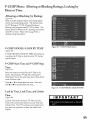
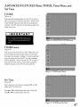
FEATURES Menu: TIMER, Timer Menu, and
TIMER
(Figure 34)
The timer will automatically turn the TV on (if it is
off) at the time you schedule and select. When ANT
is the selected input, you may select any memorized
channel
The TV will tune m this channel when the
timer turns it on.
5_.Zig
TIMER
7_/
menu
(Figure 35)
The timer can be turned On or Off When On, you
need to select the time and the dacyto turn On and
the input and channel to display. At your preselected
time, the timer will turn the TV on and a message
will be displayed, "Press a key for the TVm stay on."
A W button on the remote control must be pressed
within 5 minutes or the TV will turn itself oIE
Figure
35. TIMER
menu (TimeO
Set Time
(Figure
36)
Select the hour and minute, including
when the TVJs to turn on.
Press • or • to slowIy adjust the time.
hold • or • to quickly adjust the time.
AM or PM,
Press and
Figure 36, TIMER
menu (Set Time)
47
ADVANCED
Channel
FEATURES
Menu: Set Day, Input, and
Set Day
(Figure 37)
Select the da_ that the TV will turn on automatically.
You can select Eye.day, Mon-_¥i (Monday through
_¥iday), or the individual den of the week.
Fig_¢re 3Z TDI/IER
menu (Set Day)
NA_2N
tIINNU
Input
(Figure 38)
Select the input to use when the timer turr_s on the
TV. If the TV is alrea@ on, the timer will turn the
TV to this selected input.
Figure ,38. Thl/IER
menu (Input)
Channel
(Figure 39)
If the selected input ks tbr AWl;
the TV to the selected channel
TIMER
menu (Chunne 0
the timer will turn
ADVANCED
Enhancement,
FEATURES Menu:
PC Power Save
Video Mute, Black
Video Mute
(Figure
40)
Video Mute, when On Iets you disq?lay a blue
background when no signal ks beirg received on
Inputs 1-2, Component 1-2, and MonLink,
Fig_¢re 40, Video Mute
Black Enhancement
(Figure 41)
The contrast in dark scenes is enhanced
picture
quality,
tbr better
Brighter scenes will not be affected.
PC Power Save
(Figure 42)
Figure 41, Black Enhancement
Your Mitsubishi fbllmvs the VESA approved DPMS
Power Managernent guiddines.
This power management f_:ature is an energy saving
function that automati_lly reduces the power
consumption of the display-when your keyboard or
mouse is inactive fbr a flxed period of time. Your
display- will go into "standby" and the screen will go
to black. The timer light will display- amber while in
"standby". % activate PC input again, simply move the
mouse or prms a key on the keyboard.
Figure _
PC Power Save
49
AUDIO/VIDEO
AUDIO/VIDEO
SETTINGS
Menu: Overview
SETTINGS
Menu
(Figure 43)
Each input has its own A!V memory. You can adjust
each input's A!V memou in two wa_. You can use
the menu or the remote control
AiV Memory
Reset
A!V Memow Reset will return the currently selected
input's A!V memory to the thctory settings. To reset
an input's A!V memou, select A!V Memou Reset,
select the input you want to reset, and press EN'K
TV Speakers
Thks selection will turn on or offthe
TV_ internal
Figure 43. AUDIO/VIDEO
SETTINGS
speakers. You may select Offwhen sendir_ the sound
through a separate stereo s;_tem or surround sound
A!V receiver.
Audio Output
Select Fixed i£your audk) receiver or stereo s;_tem can
be controlled with a remote. This a11ows you m adjust
the volume with the sTstem's remote control or the TV
remote control, if compatible. This settir N is better
for surround sound receivers. Select Variable if your
audk) receiver or stereo sTstem cannot be controlled
with a remote. This allows the TV's internal circuit W
m adjust the volume.
AUDIO SNIW1NGS and
VIDEO SNIW1NGS
(Audio Settings, Figure 44)
After selecxing AUDIO SETTINGS
or VIDEO
SETTINGS,
you can adjust the settings by pressir N
A, V, I, or •. For descfiptior_s of the individual A!V
settir_s, see AUDIO!VIDEO
Setting Descfipfmns,
pages 50-52.
Using the AUDIO
and VIDEO
Figure 44, AUDIO
SETTINGS
Buttons on the Remote Control
i. Press AUDIO or VIDE() to cycle through the available settings.
2. Press _ or • to adjust the setting. After 5 seconds of inactivity, the setting display will disappear.
50
menu
AUDIO/VIDEO
Setting Descriptions:
signal is broadcast, the letters "SAP" will be
displayed when you tune m the channel.
Audio Settings
[]
Bass
Enhances
• Mono: Reduces background noise and should
be used when receiving a weak stereo audio
signal All audio will be played mono with
this settir N,
or reduces low f_equency sound.
[] Treble
[]
Enhances
Balance
or reduces tfigh t)equency
sound.
[]
Adjusts the level of sound between the leI_ and
right speakers.
[]
Surround
Creates simulated stereo and surround
Your choices are:
ef}[:cts.
• Off: No surround eft_c_s. Use this setting
when using an A!V receiver with Dolby ':'_
Pro Logic Surround, or Dolby ':'_ Digital
Surround.
• Simulated
simuIated surround
stereo program.
eI}_ct when watching
Listen to (fi)r INPUTs)
Is not available.
[]
Level Sound
Automatically equalizes the volume level
of programs containing significant level
differences from one segment m another
(Ibr example, regular programming m
commercials).
% receive the best fldelity with
music programs, you can turn this settirg m
OIE
[] Subwoofer
Stereo: Your TV will create a
simuIated stereo ef}_ct when watctfirg a nonstereo program.
• Surround Sound: Your TV will create a
[]
Audio
Your TVis equipped with two stereo speakers
and a subwoofer. This thnction spedilcally
adjusts the subwoofer's outpu_ (level of sound).
a
Listen to (fi)r ANT)
Determines
how your TV will receive a broadcast
audio signal and play back the sound you hear.
Your choices are:
Stereo: DefauIt setting. The TV will
play stereo broadca_ts in stereo and mono
broadcasts in mono. The word "Stereo" will
be di_splayed when you tune m a channel
broadca_sting stereo.
NOTE: A slider will display on-screen for each
setting. The slider has a numeric value, where 63 is
the maximum, the mid-range Ls31 and the minimum
setting is 0.
SAP (Second Audio Program): Additional
monaurM soundtrack that you cannot hear
during nounal TV viewing. The SAP signal
might be related to the program you are
watching, such as a soundtrack in a foreign
Ianguage, or unrelated m the program you are
watching such as a weather report. Ira SAP
51
AUDIO/VIDEO
Setting Descriptions:
Video
Video Settings
NOTE: A slider will display on-screen fbr each
setting. The slider has a numeric value, where 63
is the maximum, the mid-range is 31 and the
minimum
[]
setting is 0.
Film Mode (Au:tomatic)
Video media uses a video camera created at 30 frames
[]
per secot_d. Film media uses a l_Im camera created
at 24 li'ames per secot_d. Examples of video media
are live TV broadcast sucll as news, special events, or
Contrast
Provides a slider to adjust the white-to-black
level. Low contrast shows avariery of shades
in darker images, while high contrast shows
darker images more uniformly black and
makes colors appear more vibrant.
video taped programs. Examples offihn media are
motion pictures, madeqb>TV movies, and many
prime time programs. Filmed media is co=verted by
the broadcaster or home video compa W m 30 f}ames
per secot_d m match TV or video stat_dards. This
conversion can leave subtle '!picture artifacts" or
conversion errors.
[] Brightness
Provides a slider to adjust the overall
brighmess of the picture.
The setfit_gs are On and OFF If you select On, the
system automatically
detects if the signal s_urce is Fihn
and corrects fi_r conversion errors. If you select Of[f;
[] Sharpness
the system will never correct f))r conversion
Provides a slider to adjust the detail and dariw.
[] Color
This functkm
Provides a slider m adjust the TV's illumination.
A lower
setting preserves the life of'the backlight lamp.
[] Tint
[] PC Setting
Provides a slider to adjust the proportion
to green.
of red
[] Color Temp (Cdor Temperature)
Allows you m adjust howwhite
displayed, Your choices _e:
images _e
Low 6500K or Low (tbr LTFV): Wt_te
images w'dl have awarm cast to them. This
adjustment is an average and can vary due to
ambient room lighfmg, video scene brighmess
and the TV's age. The Low 6500K represents
the 6500K industry standaM for NTSC (nonDTV) pictures.
• Medium: White images will be balanced
between the Low (warm) and High (cool)
settings.
• High: White images w'dl have a cool cast to
them. Thi_ setting may provide the most
realistic picture under bright lighting.
This thnction
Reset
Resets PC settings
[] H Position
to facmt'y
default.
Provides a slider to center image by moving it to
the left oi: right (available fbr PC and MonlmrLink
inputs only),
[] V Position
Provides a slider to center image hy moving it
dmvn (available for PC and MonimrLink inputs only),
[] PC Video (.'lock
Provi&s a slider m adjust PC clock frequency,
[] PC Fine Detail
Provides a slider to adjust PC image flicker (clock
[]
phase).
PC H Resolution
Provides a slider m adjust PC horizontal size hy
increasing or decreasing the setting,
[] PC V Resolution
Provi&s a sli&r m adjust PC vertical size by
increasing o1:decreasing the setting.
NOTE: For optimal picture performance,
it iv
recommended
that you adjust your video settings
Noise
Reduces minor noise (graininess)
broadca.st or input signal
52
only in 480i mode.
[] Backlight
Provides a slider to adjust the color inter_sity.
Video
operates
errors.
in the
operates only in 480i mode.
(specifically contrast and brighmess) during initial
setup. Certain iCacmrs will affect your personal
preferences, including room lighting,
and viewing angles/distance.
glare reflections
!!!!!!!!!!!!!!!!!!!!!!!!!!!!!!!!!!!!!!!!!!!!!!_!!!!!!!!!!!!!!
Available On-Screen
Format (picture
INPUTS
Format Sizes
shape) availability
SvandaM
based on Input/Signal
Expand
Expand
480i!,1 _lOp
108011720p
HD
IZ0oI=
I Stretc!i
ANT
YES
YES
NO
YES
input-1
YES
YES
NO
YEs
YEs
input-2
YES
YES
NO
NO
YES
YES
YES
YES
YES
Courponeat
1or 2 (480i/480p)
YES
YES
Component
1 or 2 (i080i/720p)
YES
NO
YES
NO
NO
DVl(48oi/48op)
YES
YES
NO
YES
DVt (1080i/720p)
YES
NO
YES
PC
NO
NO
NO
Standard
]
Default
f'ormat tbr D'I_V and Component
displays
a lull-screen
displays
tbrmat.
Anamorphic
1,85:1
DVDs
aspect ratios,
that have the 2.35:1
aspect
bars at the top and bottom
Anamorphic
of the screen, while
from side
[]
the picture,
cropping
at the top and bottom,
to reduce
3 images
Format,
The
DVDs
some of the image
Expand
the letterbox
of non-Anamorphic
Note:
evenly
(480i/480p)
Enlarges
useful
DVDs
ratio still display black
narrow (4:3) images are stretched
to side.
[] Expand
tbrmat
that have the 1,78:1 or
tlowever,
is
top and bottom
bars
or to c*_rrect narrow
that have been stretched
Expand
lbrmat
is not available
with
4:
1080il720p
tID Expand (1080i/720p)
Enlarges the picture, cropping some of the image
on both sides. This Expand lbrmat is ttseFul to
remove or reduce black side bars on tlD broadcasts
of 4:3 images with bla& bars (See page 55).
Note: Expand HD is only available with 1080i/
720p signal.
54
NO
YES
YES
NO
NO
NO
YES
YES
NO
NO
NO
NO
yo
NO
NO
I
YES
YES
DVDs are usually
Zooln
Strut&
DeFault tbrmat f_r ANT and Inputs 1-2. qt',e
Stretched tbrmat stretches narrow 4:3 images
across the screen, howewer, there is less stretch in
the center than the sides.
]
Narrow
Displays
narrow
4:3 images
and ad& stationary
[]
NO
YES
Note: Stretch is not available with 1080il720p
signal.
in the Standard
signal.
NO
Enlarges the picture, cropping some of the image
at each side, top and bottom. The Zoom fbrmat
is useful to remove or reduce the black mp and
bottom bars on Anamorphic DVDs with 2.35:1
aspect ratio.
Note: Zoom is not available with 1080il720p
signal.
Input
The Standard
wkte
YES
NOTE: You can find aspect ratios on the back of mos* DVD covers. Also, Anamorphic
marked "Anamorphic" or "Enhanced fi_r 16.9
• TVs. "
[]
I Narrow
Note:
Narrow
in their original
gray side bars to fill the screen.
is not available
wkh
1080i/720p
signal.
[]
shape
Wide (PC)
This fbrmat is only available with PC signal.
Available
W]descreen
Standard
Zoom
Picture
Format
(16:9 - HD
1080i/720p
Sizes, continued
only)
(Recommended)
X_Tldescreen
_tandard
On-Screen
Picture
Example:
HD Expand
Bars)
A "IYue HD Broadcast
(Recommended_br
4:3 images with Black Side
(480i1480p)
(Recommended)
(_br &tterbox 2,35:l
Stretd_
DFDs)
Narrow
('Not Recommended)
55
Operation of PIP and POP
Picture Inside Picture (PIP) vs. Picture Outside Picture (POP)
You have the option to view two TV shows or inputs at the same time, For example, you can watch a game
show and a sports event on another channel, or a DVD movie and more, The PIP option allows you to view
another inpuz as a picture-inside-picture,
The POP option allows you to view a main picture and another inpuz
as a picture-outside-picture
at the side (only one moving POP),
Changing
PIP/POP
Inputs
Press PIP INtr_ IL.I,_I to browse, through
POP images,
available
t_It or
MAIN
PICTURE
Changing PIP/POP Channels
POP 1
Press PIP CH to scroll up or down through
memorized channels on the ANT,
Exchanging
Program
Images
t tess EN I ER!EXCH
to exchange the main
picture with the PIP / POP picture,
Moving PIP Images
14,,W 0:.'2
P!PA_I_
Press ADJUST A, V, ', or • to move the PIP dLsplay
anywhere on the main screen,
%_.DG OLg#/
8g'2J1
Automatic POP Switching
Press PAUSE to activate!pause automatic POP
s_vitching, When automatic POP switching is
activated, the TV cTdes through memorized channels,
or strobes pictures i_om other A/V components in the
POP display,
Selecting
Press ADJUST
POP "Live" Image
A, V, 'I, or • to select a
different POP "live" image,
Freeze the PIP Picture
A'J[ O_
48Di 8_z_Je;_
V-pG 3L8%
56
_lgA0i7
Press PAUSE in tile TV Iayer to f?eeze the PIP image,
Press Pause again to return to a "live" image,
Appendix A: Bypassing the
V-Chip Lock
Bypassing the V-Chip Lock
Aider you set the lock, you need your passcode to view
a V-Chip locked program, view the locked TV, cancel
the lock, or enter the V-Chip lock menus.
If you tbrget your passcode, you can view the locked
TV without entering your passcode. When your
p_ssword is requested, press the number 9 and Q V
buttons on the remote TV control at the same time.
This process temporarily
unlocks the TV.
When enterirN the V-Chip Lock menu, this process
deletes your old passcode and prompts you to enter a
new passcode.
[MPQRTANT
57
Appendix
B: High Definition
Component
These
inputs
and DTV
Inputs
are compatible
with most standard
signals with component
Compatible
and HDTV
Input Connection
DVD
video outputs.
DTV signals am SDTV
1080i.
480i, 480p,
Please check the DTV receiver specifications
connecting.
720p,
beti_re
Input Levels with Component
Video
Y
= 1.0Vp-p (includes sync) 75ohms
Pb
= 700mVp-p, 75__ms (can "alsor_ive
signals f?om outputs lat_']cxtB-Y and Cb)
Pr
-- 700mVp-p,
75ohms (can "alsor_ive
signals _?om outputs labdcxt R-Y and Cr)
Input Levels When Used With
Component Video Signals
EIA - 770.3 Standard
Levels
Y
= 1.0Vp-p (includes sync) 75ohms
Pb
= 700mVp-p, 75ohms
Pr
H
= 700mVp-p, 75ohms
= Not Used
V
= Not Used
Input when Used With DVI
HDCP
compliant
E-EDID (Embank-Extended
1.3 compliant
DVI-D una3mprmsed,
Display Identification)
high-speed,
digital
single-link connection
Suggestcxt scan rates: i080i, 720p, 480p, 480i
58
Compatibility
Appendix
C: Remote Control Programming
AiV Receivers
Mit_ubishi ......
010,011,012,013,
............
014,360
A&rfira!........
220
Aiwa..........
225, 226, 241
B&K ........
352
Bose ..........
351
Denon ........
234, 235,236, 245,
............
246, 359,361
Fisher ........
204
Cerrard ........
213
Harman Kardon . . 215,223, 242, 362
Jensen ........
223, 229
JVC ..........
232, 233
Ke_iwood ......
200, 208, 289
KLH
........
363
Koss ..........
357
Magmavox ......
Marantz ......
Mclntosh ......
Nakmrfichi ......
Onkyo ........
Optimus ......
Panasonic ......
Parasotlnd ......
227,228
224, 350, 360
216
206, 217
209, 214,240, 247
203, 227,231, 230
219,218, 221
356
PhiIips ........
Pioneer ........
Polk A_dio ......
O_lasar ........
RCA ..........
SansM ........
Sharp ........
Sherwood ......
Sony..........
SoundDesign ....
TEAC ........
Tedmics ......
Venturer ......
V_ctor ........
Yamaha ........
223, 248, 290
205, 207
353
219,218, 221
203, 205, 227,231,230
203, 211,239
234, 237
354, 355
222, 249, 364, 365
238
212, 213,210, 211
221, 218,219
358
232, 233
201, 202, 243, 244
Cable Box
Codes
DVD Players
ABC ..........
Archer ........
Cableview ......
Citizen ........
Color Vbice ....
Comtronics ....
Cuzfis ........
Diamond ......
Eagle ........
Eastern ........
GC Brand ......
GE ..........
Gemitfi ........
Geneml Instrument
/JerroId ........
............
Hamlin ........
Hitachi ........
Macom ........
Magnavox . .....
............
Memorex , .....
Misvietime ......
Oak ..........
Panasonic ......
124
125
105
122, 105
128, 129,130, 106,107
128, 129,130,106, 107
112,113
124,125
129
134
105
112,113
122, 143
Mitsubishi ......
003
Aiwa ..........
261, 274
Apex ..........
266, 283
Bose ..........
286
Denon ........
250, 273
Ferguson ......
251
GEiRCAiProscan
251, 256
Harman Kardon . .282, 288
Hi1:achi........
270
JVC ..........
Kenwood ......
Mintek ........
Nex*Base ......
Normande ......
257
27I, 289
285
284
251
119,120, 121,122, 123
124,125, 126, 127
112
103, 124
103, 104,105, 108
128, 129,130, 106,107,
133,138
130
105
102
114
On_'o ........
Oritron ........
Paite ..........
Panasonic ......
267, 280
263, 268
262
250
PhilipsiMagmavox
Pio_mer........
Saba ..........
258, Z53,272, 290
252
251
Paragon ........
Philips ........
............
Pioneer
........
Pulsar ........
RCA ..........
117
128, 129,130, 106,107,
133,138,131
101,
116
105
115
Sampo ........
Sams_ng ......
Sawo ........
Sharp ........
SMC ........
263
261
275
260
275
RegaI ........
Regent" ........
Rembrant ......
Samsung ......
Scientific Athmta..
Signat uze ......
............
SL Mark ......
Sprucer ........
Starcom........
............
Stargate........
Teleview ......
%corn ........
Toshiba ........
Unika ........
United Artists ....
United Cable ....
............
UniversaI ......
112
134
105,138
105
112,113,194
119,124,125,126,127,
120, 12I, 122
105,101
105,
119,124,125,126,127,
120, 12I, 122
105
101,105
135,136
104
125
102
119,124,125,126,127,
120, 12I, 122
122
S)'Ivatfia........
Sony ..........
Thompson ......
Toshiba ........
Venturer ......
_¢qalta ........
_%ve ........
XWave ........
_%mmha........
Zenith ........
264
254, 278, 279
251
253, 287
281
277
269
269
250, 272, 276, 287
259
_¢qdeoway ......
_¢qewstar ......
106
129, 130
Zenith/
Drake Satellite
. , 117,100
59
Appendix
C: Remote Control Programming
Satellite Receivers
iDBSiDTV
Mitsubishi
HDiSatellite Receiver
EdmstariDishnetwork
Express Vi_......
GE ..........
Gradient ......
Hitachi ........
Hughes ........
Maganavox......
Panasonic ......
006, 173
175,82, 183,188
175
176
186
1Z_,181,184
1<_
171,172
174
Philips ........
RCAiProscan ....
Samsung ......
SoW ..........
Star Choice ....
Toshiba ........
............
Uniden ........
WebTV. .......
171,172
176,179,180,I85
192
177
1Z_
170,189, 190,
19I, 173
171,172
187
60
Codes, continued
VCRs
Mitsubishi ......
001, 002, 060, 067,
068, 061, 062
Admiral ........
055
Aiwa ..........
047, 052
A!cd ..........
049, 034, 035, 036
A_dio Dynaraic . . 031
Bell &HowdI ....
025
Broksonic ......
040, 046
Carton ........
043, 045
Citizen ........
026
Craig ........
Curtis Mathes ....
Daewoo ........
DBX ..........
Dimensia ......
Emerson ......
............
Fisher ........
FunN ........
GE ..........
Go Video ......
Goldstar ......
Gradiente ......
Hitachi ........
Instant RepLy"....
Jensen ........
JVC ..........
Kenwood ......
LXI ..........
............
Magnavox ......
Marant'z ......
Marta ........
Memorex ......
MGA ........
............
Minolta ........
Multitech ......
NEC ........
Oh'topic ......
Optim_s ......
Orion ........
Panasonic ......
025, 049, 026
065, 044, 047
063, 021,044, 078
030, 031
065
023, 038, 039, 040, 045,
046, 062, 063
025, 028, 029, 027
047, 046, 040,054
065, 044, 079, 053
05_ 069, 070, 07I
026
054
043, 065, 020,047
044, 043
059
030, 031,054, 076, 077
0301026, 031"
047, 026, 020, 02_
028, 025, 029
05I, 043, 044
030, 031
026
044, 029
060, 067, 068, 061,
062
020, 065
06_ 047, 024
030, 031, 054
044, 043
048, 041,055, 026
046, 040
043, 044, 041, 042
VCRs
Penne_ ........
............
PenVax , .......
Philco ........
............
Philit_s ........
Pioneer ........
Pmscan ........
............
Quasar ........
Radio Shack ....
............
RCA ..........
............
Realistic ......
............
Samsung ......
Sansui ........
Sawt_ ........
Scott ..........
............
Sears..........
Shaintom ......
Sham ........
Signature 2000
Singer ........
Sony ..........
............
SV2000 ........
Svlva_ia........
Syraphoni¢......
'laashiro ........
044, 020, 065, 025,
03(;, 031
020, 031, 065
05I, 044, 047, 043,
046, 040, 063
05I, 043, [}44
043
06_. 020, {)43, 044, 051,
066, 021, 022, 053
041,042_ 043, 044
053, 044, 025, 056, 029,
06(., 047
053, 065, 020, 043, 044,
049, 05L 066.02L 022
044, 025, 056, 029, 06(
047
057, 022- 024, 053
046, 040, 072
025.029
021,022. 024, 029, 060,
067,068- 046, 040
025, 026, 027, 02K 020
037
055, 056
. . 047, 055
037
04K 049, 050, 0_, 014
075
04?
05I, 043, ¢)44,047
047
026
'laatung ........
03G, 031
TEAC ........
030, 047, 031
'I)chtfics ......
041,042, 043, 044
Teknika ........
044, 04Z 032
%shiba ........
021
Totevlsion ......
026
_ctor Research . . 031
Wards ........
055, 056, 029, 064, 026
'_atrmha........
025, 030, 03_
Zenith ........
004,026
Appendix D: Cleaning and Service
Cleaning
• DO NOT spray liquids or deaners directly on the
TV s surfaces.
Normally, light dusting with a dry, non-scratching
duster will keep your TV dean. If cleaning beyond
this is needed, please use the tblkrccing guidelines:
• DO NOT scrub or rub the TV harshly.
gently.
Wipe it
First, turn offthe TV and tmplug the power cord
f)om the power outlet.
"Fop and Sides of the TV:
•
Gently wipe down your TV with a soft, non+
abrasive cloth such as cotton flannd or a dean
cloth diaper, lightly moistened with water. Dry
with a second dry, soft, non-abrasive cloth.
For oily dirt, add a fray drops of mild liquid
detergent, such as dishwashing detergent to the
water used to moisten the cloth. Rinse with a
second cloth moistened only with water.
a third dry, soft, finn+abrasive cloth.
Dry with
General Cleaning Warnings:
• DO NOT allow liquid to enter the TV through the
ventilation slots or any crevice.
• DO NOT use a W strong or abrasive deaners as
these can scratch the sur{::aces.
• DO NOT use a W cleaners with ammonia, bleach,
alcohol, benzine, or thinners as these can dull the
surfi_ces.
61
SIDE PANEL FOR INPUT
TERMINAL
Tat_
62
Index
Anmnna ro a Cubic Box or VCR 15
Audio Receiver 17
Audio Components to the Cable Box or VCR 16
D'[V Recelver 19
DVD Player 18
Monitor Link-* 21
S-Video Device 18
Connections Aff_-cttile PIP and POP 22
A
A/V
Memory
Reset
50
Receiver, ()onnecting
17
Activating the PIP and POP 29
Advanced Features Menu 34, 4_49
D
DayIight Saving_ "Bme Menu
Antenna
Channd Edit Men_ 42
DTV Input Connection
t)TV Receiver with
{'onnccting 14, 15
Appandicvs
A: Bypassing the V-Chip Lock 57
B: High Definition
input Connection
Compatibili
Audio/Video Settings Menu .34, 50
AFV Memory Reset 50
Audio Output
50
TV Soeakcrs 50
Audio Settings Menu 50
Audio Settings Description
51
E
Entering the Passcodc fbr V-Chip 44
Exchanging Ptogram hnages PIP and POP 56
Frcc-ze the
PIP 56
Side-By-Side Picture 56
Front Button Lock 38
Fron= Control Panel 10
54
!
lnpu_ Menu 4,8
input Assignment Menu 35
input l_cvds when used with
RGB "video Sigrlals 65
Component V3deo 58
Componant Video Signals 58
Input when tlsed with t.)VI 58
Back Panel InpuffOt_tput
11
Nack Enhm,_cement Menu 450
57
C
Cable Box. Connecting 15. 16
( ;options Menu .3.3.39
Backagrotmd 40
Closed Captions 40
Changing PIP/POP
[2hannds 5;6
Inputs 56
Channel Menu 41. 48
(;hannd Edit Menu 33. 41
Channel Selection 26
Clock Setting
Attm 37
Manual 36
Coaxial I_ead Antenna, Connecting
(_lor Balance Menu 46
W 58
F
8
Bypassing the -VLChip Lock
58'
ComponantVideo Connections 19
DVD Player with Component Video 18
C: Remote Control Programming Co&s .59
D: Cleaning and Service 61
Automatic POP Swirchlng 56
Auto (_lor Correction Menu 46
Available On-Sca'een Format Sizes
37
Compatibility
L
Language Menu
Lack Time 45
38
M
14
Component Input_ Connection Compatibility 58
(_mpositc Video with Audio. Connecting 16
( ;ONNFCTING
Antenna or \Vdl OutIct (;able 14, 15
,_nrenna ro a (;able Box and V'CR 16
Main Menu Screens: Overview 32
Memorize Channels Menu 35
MemotiTx_Menu 35
Memoty Menu 41
Menus (also see individual topic)
Advanced Featt_es 46
Audlo/Video Setting. 50
Captions .39
Channel Edit 41
Main 33
Setup 35
"vtChip Ia_ck 43
MonimrLink. Connecting 21
Moving PIP Images 56
63
N
U
Name Menu 41
Unloek*l_me 45
Use of the Remote Control with Other AN Products 2Z 28
Using the AUDIO and VIDEO Buttons on the Remote Control
P
PIP and POP
Actlwating 29
Changing 56
Freezing 56
How Connections Affbct 22
V
Operation 56
POP "I.ive '_Image, Selecting 56
R
Remote Control Functions
(.;are 25
Channel Selection 26
Operation 25
PIP and POP 29
OvmMew of the _IW Layer Button 24
Sleep Timer 26
Spedal Functions 29
Use with Other Brands of Audlo and Video Doducts 27
Reset Color 46
Reset Facxory De_Saults50
S
&Video
Audio, Connecting 16
Device, Connecting 18
Safeguards 4
Separate UHF and VHF Antennas, Connecting
Setting Up the V-Chlp taack Pa_se_de 44
Setup Menu 35
Set Day Menu 3(£ 48
Set Time Menu 47
Side Panal for lnput%*:mlnal
Sleep Time*: 26
Spedal Features 9
SO.¥_* Using the
Menu Sea'een 42
Remote Control 42
62
Stereo Audio S):stem, Connecting
17
T
Timer Menu 47
Time Zone Setting 37
*ti'oubleshooting 65
_l_' Speakers Menu 50
Twin Lead Antenna, Connecting
64
14
14
VLChlp
Allowing o1:Blocking by Ratings 45
F_xceptlons: 43
Start Time and Stop *l_me 45
VX2hlp Lock Menu 34, 4345
Overview 43
Signal Information 43
_.iLChlpRating Menu, Selecting 43
Video Mute 49
Video Settings Desea'iption 52
Video Settings 50
Viewpoint Menu System 32
W
\gaI1 Outlet Cable, Connecting 14
• The TV remote coi_troi does not work.
• Check
"
" are installed
'
that the batteries
correctly,
Check that die _elected sw wb is set to TX.' .
• Be *toBartller than 20 Feett}om the q_V when uslng the remote control,
• Avoid *lslngunder or near strong fluorescent iighdng.
• The TV takes several seconds to respo*idm cha_ind commmids.
• Use the tkree dlgiI number, l.e 002 _r the*me 2
• Avoid mqng raider or 1+ear_trong fluorescent iiglNng.
• %u canuo_ access a diamieI,
• Use _mmberkeys instead of CHANNEL _p/dowm
• Be sure I)l_ cha_melym_ Wa_it Io v[gw is i_i _nen_ory.
(.,beck that the _1V £s turned to the correct input so_ce fbr _lat cbamml.
by press ng the ]NPI T bauo *,
Make sure die %'-Chipsetting is Off pane 44),
• On-screen displays appear each time yon cha_igea fhncdon.
• Tiffs is part of_iornmI TV operatiom
• You ca*mo_program the TV to mrn on automatically.
• The TV mV be locked.
• The clock may _iotbe set
• There is no sotmd even when the _'ohmieis turned up.
• Check
to see l_the
•
..... MUTE banmil_ o_i,
• The TV's "Linen to:" seul_tg may be set to SAP,
• C,beck that _TV Speakers" se**i_igis On.
• ?o_*have fbrgotteT*Dur lock passcode,
• See Appe_*dlxA, Bypassing the VCbip Lock (page 57),
• Power is s*ldde_*ty
turned off:
Check TIMER and PC Power Save settings.
• Make sure *he %<Chipsett
ng is Off(pane 44),
• Not all inputs ca*ibe dlsplwed as a PIP (page 22),
• The smmd does not match the screen pier,are,
• If uslng aereo or A/V reveiverstreakers, cl eck hip_t 5dectlo*i o i il*e
s_ereo or AiV recdver.
• If using aereo or A/V recei_'er,check thai AUDIO is PromMONITOR
OUT oti TV%back panel,
• There is a large Neck or gr_ rectangle on the screem
Ie.d mlonnatlon being broadcast Turn OKra the CAI ]'IONS menu
(page 39).
•Plcmre i_out oPibcas or colors are m)r allgnem
(.lie& tile S}l_pues_. ColoFview. a_tdlI_pllt
skglial
settln=g_(page 52),
• You canno_ see .qpitt _re when }xmplay a VCR _ape.
• Ifyou cmmec_eo Four VCR w_thA V canes. _se tim INPWr batm_i
ut _elect the hipm source {INPUqM or INP'UT-2) that the VCR is
connected lo.
• Check _our VCRs mvneFs gtfide i_>r
Pusther tmable_hoofing.
• V-Chl_ Lockis _o_ working.
• Make a_re lliat V-Chip is On (page 43),
If V-Clrm I{oursiLod_ by I'mIe _s curremly set to &sable the V-Cb+p
lock- tile _vcCllipMII _or block programnnng.
• Cannot set adlustments to f,_ctor_setfin_
• bltlow the steps below to reset system defaults to factor}' settings,
1.Press Ihe MENU button fbllowed by number hmto_m1,2.and 3 ou
the remote control,
Restdt The above steps actbate d_e Reset Sys*eml)ei_flts mere screen
2. Press the ENT bauon o_td_e remote control
Restdt :The setting_ reset to l;actorydel;allts.
i, Pres_ the HOME or MENU buiton on tile remote control to return to
die HOME or MENU screeem
IMPORTANT: Tbb Palictlo*iis _ot recommended miless it is man,dainty
to re_et system defiult._m fictory setti_igs, This c_eraIion CANNOT be
undone and al_cuaoms settlnm will be ended
65
NOTES
66
MITSUBISHI LCD TV LIMITED WARRANTY
MITSUSISHI DIGITAL ELECTRONICS AMERICA INC ["MDEA"} warrants to _e anginal purchaser of this LCD TV that if 3urohased from an authorized
MITSUSISHI AudiofVideo Dealer, should it crave defective by "eason of imorceer werKmansnJo anotor materlan
{:. Part{: Al {:{:rts are warranted for a ceried of one year from the d{:te of the original purchase at retail We win reo{:_ror rea_ace, at our {:ption, any defective part
w_tneut cn{:rge for the part Parts used for reolecement may oe repl{:ced with those of hke kind aandqu{:lity {and may be new or remanufactuted Parts used for
•ec_{:cement are warranted for the remainder of the otig_na=w{:rramy pen{:c
b Labor Wewiilorovidethelaberfer{:w{:rrantyrep{:lroy{:n{:uth{:fizedMITSUSISHI
{:t ret{:H.
servicecentarwithoutch{:tgefor{:n{:ye{:rfromtheoriginald{:feofpurehase
c. Notice. To {:brain warr{:cty sarc_ce,you must nafif_, an {:uthodzed MITSUSISHI service center of any defect within the app_Jcao_ew{:rramy sme per}co.
1 TO OBTAIN WARRANTY SERVICE
{:. Contactyour nearestauthorizedMITSUSISHIservice center_whose nameand {:ddre{:scan be obtainedfrom ,our MITSUBISHIdealeror bywriting or ceiling
MDEA at the addressand teleanenenumcercrowcesbelow.
b Warranty service will be orevided at an authorized MITSUBISHt service center otOVli'J
8d that your te_ev_s_en_sioceteo within the geegrapmc territory cusrom{:rtly
cevere{: ay an authorized MITSUSISH{ service cecter. You must either deliver ot cetry4n your television to an authorized Service Iocafi{:n at y{:ur own expense, ano
pay for any traveJ an{:ror transoottati{:n costs to and from y{:ur none
c. Proof of 3otch{:se date from an {:uthofized MITSUSISHI dealer ts reauaes when requesting warramy service Present y{:ur S{:tes rece_af{:r ofhe_ d{:cument which
est{:gtisMesareofanddateotDurehase.
THERETURNOFTNEOWNERREGISTRATIONCARDISNOTACONDITIONOFWARRANTYCOVERAGE
However
ple{:se return the Owner Rag_strattsn Card so that we can cect{:ct you snou_o {: q Jestion of sate_:_{:rise which coctd affect you.
2 This LCD TV uses a revolutionary technology that includes film tr{:nsister to create the screen image. This techn{:legy creates the image using sm{:N {:ot& or
31ctotaelementa(p_xels] YourLCDTVism{:nutecturedt{:ahightsvelofperfectier
infect 99.Bg%L_erfectinthenumberofpreperlyfunctioningpixels
Asintube
telev_sl{:n S{:metlmes a oixel is continuously {:ctive ot inactive. Our stand{:rd ts clear _{:ur 3i×els must be 9999% cerfect in the number of properly functioning
3JY_IS
3 THIS WARRANTY DOES NOT COVER:
{:........... Up to .gl % pi×af outages (sm{:ll dot picture elements th{:t are dark or incorrectly illuminated)
b......... Cosmetic damage or cem{:ge to this LCD TV or to any emer pre{:ucts where such cem{:ge _scause{: oy unauthorized m{:dificettsr a_terot_er reoa_ret{: Or
service of the prceuct ay anyone other than an anthbezed MITSUSISHI service center; physical abuse to or mi{:use of the product (_nclud_ngany failure t{: carry out
any m{:intenance as described in the Owner's Guide or any prosuct cemaged by excessive physical or electrical stress}; any product{: that have h{:d a seri{:tnumber
or any part thereof altered, defaced or removed: oro{:uct use in any manner contrary to the Owners Guide 0nclad_ng, but not iimceo tc 'mpr_me{: im{:ges on the
viewing screen); freight damage ot damage due to improper shipping matrices: {:{:mace causes ay use of third p{:rty m{:unsng crackers {:r st{an{:sor any {:{:mace
causeo ay acts of God or other factors beyond the reasonable centroJ of MDEA such as 3ower surue {:{:mace cause{: ayemectnce_system or _gmmng. This warranty
{:lse excludes service where no defect in the orceuct coyotes un{:er tms warranty is found, service calls related to unsafisfactor_ {:uo_oor wsua_ reception or s_gn{:
unless causes aya defect in the oroouct that is coyotes unser m_s warranty {:_ costs, expenses or any other cem{:ges adsing from product installafion, or set-ul)s
any adiuafments of user controls _including contrast, cr_ghtne{:s, color, tint, fine tuning, sharpness), {:thor {{:dju{:tmemnecessary to prepare the unit for display ot use
connection w_tean:_externa_ TV tuner computer System {:urJ_oreceiver. {:rearms caole or satellite systems or service Oforceucts ourehased or serviced outaide
the US.A Please censu]t the operating instructions contained in the Owner's Guide furnished with the oroduct for inferm{afion reg{:roleg user controls
4 ANY EXPRESS WARRANTY NOT PROVIDED HEREIN, AND ANY REMEDY WN C_" BUT FOR THIS PROVISION MIGHT ARISE BY IMPL CATION
OR OPERATION OF LAW IS HERESY EXCLUDED AND DISCLAIMED. THE IMPLIED WARRANTIES OF MERCHANTABILITY AND FITNESS FOR ANY
PARTICULAR PURPOSE ARE EXPRESSLY LIMITED TO ATERM OF ONE YEAR
5 UNDER NO CIRCUMSTANCES SHALL MDEA 3E LfABLE TO PURCHASER OR ANY OTHER PERSON FOR ANY INCIDENTAL
CONSEOL ENTIAL DAMAGES WHETHER AR SING OUT OF BREACH OF WARRANTY BREACH OF CONTRACT OR OTHERWISE
SPECIAL OR
6. Some states de not allow limitations on how _ongan _mpliodwarract_ sat& or the exclusion or limitation of incidenta scec_a_or censeeuensa_ {:amage& s{: the
above limitati{:ns or e×ciu{:ions may not apply _oy{:u
7. This warranty gives you specific leg{:l rights, and you may {:_sonave ctner t g_ts wn_cn vat/from
state to state
8 BEFORE REQUESTING SERVICE ole{:se rewew the instruct}on oce_et to msute proper _nsra_lat{onano correct cust{:mer contre] {:¢.ustmect. if the oreblem
persists, contact y{:ur nearest MITSU BISHI Dealer for the name(s; of {:uthbezed MITSU BISHI Service Canter(s}. If y{:u are unao_et{: obtain this information, ole{:se
call 800-332-2'H9 or write u{: at the address below
MITSUBISHI
MITSUSISH, DIGITAL ELECTRONICS AMERIC,_ INC
935I Jeronimo Road
#vine. 0A 82_16-'1804
IRETAIN THIS
PORTION
FOR
YOUR
RECORDS
I SERIAL
MODEL
NO,
NO.
DEALER NAME
STRE ET ADDR ESS
CITY
PHONE(
STATE
)
PURCHASE
ZIP.
DATE
DIGITAL
TE
LEVISI
If you have questions
advisors
ON-q
regarding
at (800) 332-2119
_
your television,
please call our Consumer
Relations
or send an email to:
[email protected]
To order replacement
remote
Department
553-7278
at (800)
www.Mitsubishi-tv,
controls
or an Ownaer's Guide,
or contact
us through
plea_se call our Parts
our web site at:
corn
.....
_
"
"
Q2003 Mltsub_st_"Digital
E1ectromcs
America,
Inc
.
Printed
in the U.S.A,