1
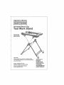
Universal
Bench Top
TooU Work Stand
Model No.
320,19730
CAUTION:
Read, understand and follow all Safety Rules
and Operating Instructions in this Manual before
using this product..
Sears, Roebuck and Co.
Hoffman Estates, IL 61)179 U.S.Ao
Visit our Craftsman® website:
www.craftsman.com
= WARRANTY
• SAFETY
° UNPACKING
° DESCRIPTION
• ASSEMBLY
° ADJUSTMENTS
° MAINTENANCE
Warranty
Page
...........................................................
Safety Symbols
2
Page
3
Salety Instructions
........................................................................
Unpacking ..............................................................................
Pages
Page
4 -9
9
Assembly ...............................................................................
Pages
9 - 16
Maintenance .........................................................................................................
Sears Repair Parts Phone Numbers ............................................................
Page 17
Beck Cover
ONEYEAR
..........................................................
FULLWARRANTY
ON CRAFTSMAN
_ PRODUCT
If this Craftsman product lails due to a defect in material or workmanship
within one year
from lhe date of purchase, RETURN ITTO THE NEAREST SEARS STORE OR PARTS
AND REPAIR CENTER OR OTHER CRAFTSMAN
OUTLET INTHE UNITED STATES
FOR FREE REPLACEMENT,
If this Crafleman product is used for commercial
lot only 90 days from the date of purchase
or rentaf purposes
this warranty applies
This warranty gives you specific legal rights, and you may also have olher rights, which
vary from stale te state
Sears. Roebuck and Co, Hoflman Estates_ IL 60179
SAVE THESE INSTRUCTIONSf
READ ALL INSTRUCTIONSt
1
1
]
t
The purpose of safety symbols is to attract your altention Io possible dangers
The safety symbols, and tile explanalions
with them, deserve your careful
eliminate any danger. The instructions
and warnings lhey give are no substitutes
altention
understanding,
symbol warnings DO NOT by lhemsetves
for proper and
accident
prevention The
measures
t
t
Z_ WARNING: BE SURE to read and understand all safety instructions in
this manual, Including
all safety alert symbols
such as "DANGER",
"WARNING"
and "CAUTION",
BEFORE using this tool stand. Failure to follow all instructions
tisted below may result in electric shock, fire and/or serious personal injury_
SYMBOL
J
,_1
MEANING
SAFETY
ALERT SYMBOL: IndicatesDANGER,WARNING,
OR
CAUTION_ May be used in conjunction wl|h oliver symbols or plctographs.
Fatlure to obey this safety warning WILL result in death or
sedous injury to yourself or to others° Always follow the
safety precautions to reduce the risk of ffre, electric shock
and personal Injury.
t
_WARNtNG
[Z_
J
i
CAUTION
DAMAGE
Failure to
obey tothis
safety or
warning
CANAlways
result follow
in death
tf serious
injury
yourself
to others.
theor
safety precautions to reduce the risk of fire, electric shock
and personal tnlury.
I|
PREVENTION
1
t
1
1
AND INFORMATION
MESSAGES
These _nform user at important Information
andtor instructions
that couid 10ad to
equipment or other property damage _f not _al_ewed, Each message is preceded by the
word "NOTE:" as tn lhe example below:
NOTE: Equipment
are not followed.
I
Failure totoyourself
obey thisor safety
MAY damager
result In Always
personal
injury
others warning
or property
follow the safety precautions
to reduce the risk of fire,
electric shock and personal injury.
WEAR
YOUR
and/or
property
damage
may result If these
instructions
z_WARNING:
The operation of any bench top tool can
result In foreign objects being thrown Into your eyes,
whtch can result in severe eye damage. Before beginning
power tool operation,
ALWAYS wear safety goggles or
safety glasses with side shield and a full-face shield
when needed, We recommend
a Wide Vision Safety Mask
for use over eyeglasses or standard safety glasses with
side shield, available at Sears Stores or other craftsman
Outlets_
Z_ WARNING: BE SURE to read, understand and follow all safety rules and
operating
Instructions in this manual and the operator's
manual of any bench top
power tool you use with this Universal Bench Top Toot Work Stand. Failure to do
so may result in electrlc shock, fire and / or sertous personal injury,,
WORK AREA
SAFETY
1 Keep your work area cTeaa and well lit., Cluttered workbenches
and dark areas
Invite accidents,
2, DO NOT operate power tools in explosive
atmospheres,
such as In the presence
of flammable liquids, gases, or dust. Power tools create sparks which may ignile
the dust or fumes.
3
4
5
Keep bystanders,
children and visitors away while operating
a power tool_
Distractions can cause you 1o lose control
Make your workshop
cht|dproof
with padlocks and master switches Lock tools
away when no_ in use
MAKE SURE the work area has ample lighting so you can see the work and that
there are no obstruclions that wilt interiors with safe operation BEFORE using your
bench top power too] and your Universal Bench Top Tool Work Stand.
PERSONAL
SAFETY
1., KNOW your UniversalToo!
Work Stand and the bench top power tool you are
using with It, Learn the applications and limllations, as wet] as the specilic potenlta{
hazards related to this 1ool work stand and lhe bench lop power tools yell use with it
2o STAY ALERT, watch what you are doir_g and use common sense when operating
a power tool lhet is mounled to this work sland
3., DO NOT use tools white tired or under the influence af drugs, alcohol or medication
A momenl et inattention while operating power toots may result in serious personal
injury
4°
DRESS prepare.
DO NOT wear ;ease ctothing or jewelry Put! back long hair. Keep
your hair, clothing, and gloves away from moving pads, Loose clothing, or tong hair
can be caught in moving parts Air vents often cover moving parts and should
also be avoided
Z_ WARNING: MAKE SURE this universal bench top tool work stand is
properly set up and the bench top power too] you are using with It is properly
attached to the tabletop assembly,. Failure to follow eli Instructions listed on pages
9 through 12 may result _n electric shock, tire end/or serious personal injury°
5
AVOID accidental star',ing of tools. Be sure switch is in "OFF- position before plugging
in. DO NOT carry tools with your finger on the switch, Carrying tools with your linger
on the swilch or ptugging in teo_s that have the switch in the "ON" pesilion invites
accidents.
6_
REMOVE adjustir_g keys or blade wrenches before luming the toot "ON" Awrencll
that is left attached to a rotating pad o( the tool may result in parsonat Injury
7
Do not overreach°
Keep proper footfng and balance at all times, Proper loafing
and balance enables belier centre! of the tool in unexpecled situations
|
PERSONAL SAFETY conL
8o ALWAYS SECUREYOUR
WORK= Use clamps or a vise to hold work when praclicaI.
it is safer than _Jsing your hand and frees both hands to operate tool
9_,USE SAFETY EQUIPMENT. Always wear eye protection
Dust mask. non-skid
shoos, hard hat, or hearing protection must be used for appropriate conditions,
safety
I0, ALWAYS be sure the tool work stand is sat up on a flat solid surface.
This enables better control of lhe power tool that Is attached to the wo_k stand in
unexpected situations
TOOL USE AND CARE SAFETY
operating Instructions
in thls manusl and the operator's manual of any bench top
power
tool you use with
this Universal
Bench Top Tool
Work Sland,
Failure
do
Z_ WARNING:
BE SURE
to read, understand
and follow
all safety
rutes toand
so may result in e|ectric shock, fire and I or serious personal injury.
1, ALWAYS use clamps or other practical ways to secure and support the workpioee
to a stable platform_ Holding the work by hand or against your body is unstabte and
may lead 1o less of conlrol,
2
DO NOT force the tool. Use the correct tool and bit for your application.
The correcl
tool and bit will do lho job bettor and safer at the rate for which it is designed,,
3
DO NOT use the tool tf switch does not turn It '+On" or"Off".
controlled with the sw_lch ts dangerous and must be repaired
4
DISCONNECT
the plug from the power source before making any adjustments,
changing accessories
or storing the tool. Such preventive safety measures reduce
the risk of starting the tool accidentally,
5
NEVER leave the toot running.
ALWAYS turn it off,, DO NOT leave the tool until it
comes to a complete stop,
STORE Idle tools out of the reach of children and other untrained persons,, Toots
are dangerous in the hands of untrained users,
6
Any tool that cannot
7
MAINTAIN tools with oare. Keep cutting tools sharp and cloam Properly maintained
loots with sharp cutting edges are less I_kely to bind and are easier to oontrol
8
CHECK for mfsalignment
or binding
of moving parts, breakage of parts, and any
other condition Ihat may affect the roof's operation I! damaged, have the Iool serviced
before using Many accidents are caused by poorty mainlained lools.
g
USE ONLY accessories
that are recommended
for the tool being used. Accessories
that may be suitable {m' one loof may become hazardous when used on another Joel.
ELECTRICAL
bo
SAFETY
Z_ WARNING: When connecting your bench top power tool to e power supply, ]
do not permit fingers to touch the terminals of plug when installing
or removing
|
the plug from the outlet.
ELECTRICAL
SAFETY cent°
1
Double Insulated tools are equipped with a polarized
plug (one binds is wider
than the other).Thts plug wH! fit in a polarized
outlet only one way, If the plug
does not tit futiy in the outlet, reverse the plug. If it still does nol lit+ contact a qualified
etectrfcian
to inslalI a polarized culler. De net change the plug in any way
2
Doubts insuIation D eliminates the need for the three-wire grounded power
cord and grounded powet suppty system AppIicable only to Class II (double+Insulated)
lools.
'
_ WARNING:
DOES NOT take the place
precautions
when Double
operatinginsulation
this tool..
of normal safety
3+ BEFORE plugging in the tool, BE SURE that the culler voilage suppfied }s within the
voltage marked on the tool's data plate. DO NOT use "AC onty'+ rated 1eels with a DC
power supply
4. AVOID body contact with grounded surfaces,
such as pipes, radiators, ranges and
refrigerators
There is an increased risk of etectric shock it your body is grounded
5
DO NOT expose power tools to rain or wet conditions or use power tools in wet
or damp iocations_ Water entering a power loci will increase the risk of electric shock
6
INSPECT tool cords for damage. Have damaged tool cords repaired at a Sear
Service Canter_ BE SURE to stay constanlly aware o! the cord location and keep
It welf away from the moving router.
7
DO NOT abuse the cord_ NEVER use the cord to carry the toot by eric pull the
plug from the outlet., Keep cord away from heat, oil, sharp edges or moving pads..
Replace damaged cords immediately Damaged cords increase the risk of electdc sl_eck.,
EXTENSION
CORDS
Use a proper extension cord° ONLY use cords listed by Underwrilers
Laboratories {UL}
Other extension cords can cause a drop in line voltage, resulting in a toss of power and
overheating o! tool For this toot an AWG (American Wire Gauge) size of at least 14-(jauge
is recommended
[er an extension cord of 25-1t+ or less in length. Use 12-gauge [or an
extension cord o! 50-It. Extension cords 100-ft+ or longer are not recommended_
Remember+ a smaller wire gauge size has greater capacity than a larger number
(14_auge
wire has more capacity than t6<Jauge wire; 12_jauge wtre has more capacity
than t 4-(:jauge). When tn doubt use 1he smaIlar number. When operating a power tool
outdoors, use an outdoor extension cord marked "W+A" or "W'L These cords are rated
lor outdoor usa and reduce the risk of electric shock.
_CAUTtON:
Keep the extension cord clear of the working area., Position the
cord so that tt will not get caught on lumber, tools or other obstructions
while you
are working with a power tool
EXTENSION
CORDS
conL
z_WARNING:
Check extension cords before each use. ifdamaged reptace
immediately. Never use toot with a damaged cord since touching the damaged area
could cause electrical shock, resulting In serious injury.
SAFETY SYMBOLS FOR YOUR TOOL
The label on your too! may Include the following symbols.
V...................................................................................
Volts
A ...................................................................
Amps
Hz ................................................................
Hertz
W..............................................................
Walls
mln .........................................................................
Minutes
,-_.,..................................................
Allemeling cunenl
................................
................
Direct current
n. .................................................................... No.bad speed
i_ ...........................................................................
.Class II conslruclion, Double Insulated
Jmin ....................................................................Revolullons or Slrokes per minute
Z_" ..............................................
Indicates danger, warning or eaulion..
It means atlentIon! Your salary is involved
SAFETY
OFTHE
RULES FORTHE
USE AND OPERATION
UNIVERSAL
BENCHTOP
TOOLWORK
STAND
1.. ALWAYS set up the Universal
flat stable surface
SenchTopToolWork
Stand
on s hard. dry.
2
BE SURE lheI lhe tool work stand is fully opened and locked into lhe proper "set-up"
position BEFORE mounting your bench lop power tool to the table top assembly
FOLLOW ALL set-up instructions on pages 9 through 13 in this operator's manual
3
ALWAYS properly attach the bench top power tool DO NOT atlempt to usa your toot
work stand with a power tool until the tool ts belted securely to the tabIe lop assembly
according to the instructions on page 14 in this operator's manual.
4
When using lhis tool work stand wilh a bench top power tool that has mounling holes
that DO NOT Ilne up with the p_'e--slotted holes in the tool work slend's table top
assembly, mount your power tool to a plywood mounting board (sold separately).
then mount plywood board and power tool to the table top assembly. See instructions
on page I5 of Ihis manual
5_ When operating a power loaf that is mounted to lhis 1ool work sland_ ALWAYS FOLLOW
ALL safety rules and Instructions
in the operator's
manual of the power toot.
6. When selling up your universal bench lop tool work stand and the power tool, ALWAYS
be sure you have the proper space around the work sland to safely operate the power
tool
7
-4
ALWAYS check the work stand and potter tool for damaged parts, Before turther use
of the work stand or the tool if any pad is damaged it should be carefully checked
to determine if il will operate properly end perform its intended function,
SAFETY RULES FOR THE USE AND OPERATION
OF THE UNIVERSAL BENCH TOP TOOL WORK STAND cont.
Z_ WARNING:
IFYOU I_OUNT BENCHTOP
POWERTOOLS
SUCH AS A
TABLE SAW OR pLANER TO THE TOOL WORK STAND, the feed direction ts
perpendicular
to the axis of the best stability on this tool work stand°
Aggressive
feeding of large, heavy sheet materials into these tools could
cause the tool work stand to move or tip over, causing personal Injury,
property damage, fire and electric shock. ALWAYS have another person
help you feed larger workpfeees tote tools such as table saws, end NEVER
feed pieces that are too large for the safe operation
of any tool you have
mounted to the toot work stand,.
8
KEEPYOUR
9
ALWAYS use clamps or a vise to hold workpiece when practical Using clamps or a
vise lo hold workpiece is safer than using your hand It also [fees up both hands
to operate the bench top tool
HANDS
AWAY trom the culling
drilling or sanding area,
10
AVOID awkward operations and hand positions where a sudden slip could cause
your hand to move tnto the cutting, dd]ltng or sanding area of the tool
11
NEVER reach
12
NEVER sit, stand or climb on this work stand, It is not designed or constructed to
accommodate
this lypa of use it could lip over, causing serious }n)u_ DO NOT stere
any Items above or near the toot work stand, especially
when it ls set-up with a
power tool attached, or allow anyone to sit, climb or stand on the tool work sland
to reach items
NEVER use thts work stand as a ladder or scaffold,
ADDITIONAL
into lhe cutting, ddlling
or sanding area of a tool,
RULES FOR SAFE OPERATION
Z_ WARNING'.
BE SURE to read and understand
all instructions
In this
Manual end the Bench TapTool's
Operating
Manual before using the tool on
this UntversatTool
Stand. Failure to follow all Instructions
listed below may
result tn electric shock, fire anger serious personal Injury.
1. Know your Universal BenchTopToolWork
Stand and the power toot you are using
wtth it. Read both operator's
manuals carefully° Learn the applications and [imitalions.
as well as the specific potential hazards related to the tooi mounted on the work stand
Following this rule will reduce the risk of electric shock, fire or sedous injury
2.. ALWAYS wear safety glasses or eye shields when using power tools., Everyday
eyeglasses have only impact-resistant
lenses; they are NOT satety glasses,
3. PROTECT
4
your
lungs,
Wear a face mask or dusl mask if the operation
is dusty
PROTECT your hearing,, Wear appropriate personal hearing protection during _se
Under some conditions noise Irom power tools may conlribute to heating Iosso
5 ALL VISTORS AND BYSTANDERS
operator of the tool wears,
MUST wear the same safety equipment
thai the
G INSPECT the tool cords periodically
and if damaged have them repaired
nearest Sears Service Center, BE AWARE of the cord location.
at your
ADDITIONAL
7
RULES FOR SAFE OPERATION
cont.
ALWAYS check the tool work stand and the power took you are using with it for
damaged parts_ Before further usa of the tool a guard or other part that is damaged
should be carefully checked to delermlne if it will operate properly and perform its
intended funclion, Check for mtsalignment
or binding of moving parts, breakage
of parts, and any olher condition that may affect the leers operation A guard or other
pad that Is damaged should be propedy repaired or replaced aL a Sears Service Center.
8, INSPECT
and remove
all nails from
lumber
before
using
a power tool
9, SAVETHESE
INSTRUCTIONS.
Refer to them frequently and use them to instruct
others who may use this tool stand. If someone borrows this tool stand, make sure they
have these instructions also
Alter taking the Work Stand out at the box, check !or misalignment
or binding of moving
parts, bending or breakage of parts, and any other condition that may affect the Toot Work
Slend'e operation, If any part is damaged, return the Too] Work Stand to your nearest Sears
slore or Craftsman outlet to have the Work Stand rep}aced,
Z_ WARNING: If any parts are bent or broken, DO NOT attempt to set up
ToolWork
Stand, DO NOT attempt to mount and use any power tool on e
defective TooI Work Stand. Failure to do so could result in possible serious
tnJury_
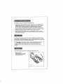
UNFOLDING
t
AND SETTING
UP THE TOOL WORK
STAND (Flgso 1-15)
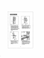
Afteryou
take the
ToolWork Stand out of carton,
place it fiat on floor in front
of your feet as shown.
Ftg_ 1
Fig_2
2o Take hold of red
Locking/Carrying
Handle (A)
and rlght side of the Tab|e
Assembly (B) then unlock ted
LockingJCarr¥tng
Handle (A)
by pulling handle towards you,
Fig,, 3
3 Take hold ofredTableTop
Assembly Handle (C) and lift
Table Top Assembly up as shown°
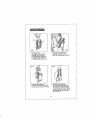
Fig,, 5
4
Continue liftlngTableTop
Assembly up while Base remains
tn place on floor as shown tn photo°
"_
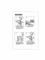
5. Continue ItfftngTableTop
Assembly up until the Table Top
Assembly is completely Vertical,
Spread the legs of the Tool Stand
and apply pressure to Base Bar (D)
with your foot so that tool stand
does not move,
10
Flgo 7
Fig,, 6
6,
7, With your foot still on the Base
Bar, take hold of the Support Bar (F)
and pull up until its Chrome
Extenslon Bars are also fully
extended and lock in place Pull the
legs further apart to form an "X",
Hold down the Base Bar Legs
(as shown) by placing your foot
on the Base Bar. Pull theTable
Top Assembly straight up until
the Chrome Extension Bars (E),
attached to the Table Top Assembly,
are fully extended° Be sure the
Chrome Extension Bars lock
fn place°
9
B, With your foot still on the Base
Bar, lower the Table Top
Assembly onto Support Bar (F)
while making sure that the
Support Bar is placed Into the
Notch (G)_
11
Pull the Spring Loaded
Locking Pin (H) back so that the
Support Bar and Table Top groove
lit together securely, then release
the Spring Loaded Locking Pin
so that the Table Top is locked
into position.
Ftgo 11
_-_!'!:
_"
_'I
I
10. To change the width of the Table
Top Assembly
working area,
turn the TableTop
Assemb/y's
two Clamp Knobs (I) clockwise
to unlock them ss shown
Close up view of Table Top
Assembly's
clamp knob.,
Fig 13
:;=_iii_
I
12
After loosening
the Table Top
Assembly's Clamp Knobs,
adjust the Table Top Assembly
to the desired position to mount
your power tool
13
12
Be sure that after adjusting the
wldth of the Tabfe Top Assembly,
you lock the two Clamping Knobs.
Th_s is done by turning them
until securely tightened.
I
I
I
I
Fig- 15
Fig,, 14
14., Unlock 3-Inch CasterWheels
by Lilting Locking Lever on
each wheel to the "UP" position.
15
Lock Caster wheels in place by
pushing the Locking Lever to tile
"DOWN" position.
PARTS LIST t CALLOUTS (Fig. 1B) :
Fig,, 16
_
Q
Q
Spring Loaded
Locking
PTable Top Handle
Table Top
AssemSly
Notch
TableTop
Assembly's
Clamping
Knobs
able AssembI
Support Bar
Chrome
Extension
Bars
®
Base
Support
Rubber
13
Bar
Foot Pads
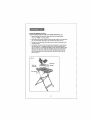
MOUNTNG
BENCH TOP TOOL
SUCH AS MITER SAW TO THE
TOOL
WORK
STAND
(Fig,
17)
1
Before mounling your bench top tool, make sure Ihe Casler Wheels
are in the "DOWN" or locked position
2,
Check bench top tool |or number of holes and their location for mounting
tool This information should be in the manual for the bench top tool
3,
Choose the corresponding
Tool Work Stand
4.
Change tile width el the Table Top Assembly it necessary to accommodate
the bench top looL To change the widlh o! the Table Top Assembly, sea
Figs. t0 th_'ough 13 in Untoldtng and Selling Up lhe Tool Work Sfand., Place
the Bench Top tool on lhe Table Top Assembly, align the mounting holes in
tile bench lop tool with 1he holes on the table lop assembly, and use the
bolts recommended
in your bench top tool's manual to connecl them as
shown in Fig. 17
hole locations
on tile Table Tap Assembly
Table Top
14
the
ol the
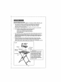
MOUNTNG
BENC H TOP TOOL
SUCH AS ATABLE
SAW OR PLANER
!
TOTHETOOLWORK
STAND
(Fig.
18)
This method of mounting is used for tools that do not fit the pre-slamped tool
mounting slots in the Table Top Assembly el the Tool Work Sland, Examples
would be Scoot[or Saw, Drilt Press, Disc/Belt Sander, Planer, Bench Grinder.
Band Saw, and Rle Culling Wet Saw.
2. For lhts method,
a sheet of plywood
16114X 29VB X _/4-inch tl_ick ts recommended
3. This method of mounting requires two sets of mounting holes;
One set for mounting the tool to the plywood, and
Another set for mounting the plywood and toot to
tile pre'-stamped slols in the Table top Assembly of
the Tool Work Sland
4
5
Place the plywood onto the Table Top Assembty of the Too[ Work Stand and mark four
holes wilhin tl_e pro-stamped slotted areas on lhe Table Top Assembly, Use bolls,
washers and nuts as shown in Fig.. !8 to attach the plywood to the table lop assembly,.
NOTE: BE SURE the Bolls are long enough to go through plywood, table top
assembly and nut.
Mount the bench top tool to the plywood using the holes tn the base of the too!,
or lollow the template in the tool's operator's manual., Use the boils recommended
in your bench top leers manual to connect the bench lop tool to lhe plywood.,
NOTE: Bolts should be long enough to go through base of tool, plywood, and nut.
Fig_ 18plywood
;
•
'
.
'
.,/,Boat head
_ '-"
'
,_ WARNING:For somebench
top tools (such as a saw). a hoZe
must be provided in the plywood
table top under the saw to allow
sawdust to fail through to redtfce
the possibility o_ fire or damage to
the saw, ALWAYS BE SURE to
read and follow the instructions
provided in the beech power 1eel's
operator's manual.
15
FOLDINGTOOLWORK
STAND
DOWN
(Refer
to Illustration
Figso 1 to 15 on pages
Once Bench Top Power Tool is removed
'_ Keep Caster Wheels in locked position
2, Loosen
Tool Stand's
Clamping
FOR STORAGE
9-13)
from Tool Stand;
by pushing Locktng Lever"Down%
Knobs,,
3
Open up Tabfe Top Assembly
to its fully extended
4
Pull back Spring Loaded Locking
size. Ih_n re-lighten
Pin and remove Supporl
Ciamping
Knobs
Bar lrom Table Top groove.
5 With your foot on the Base Bar, raise Table Top Assembly 1o upright, vedicaf position.
Close up legs of Tool Stand and push down on Chrome Extension Bars unltl fully lowered
6
Lower Table Top Assembly,
7
Use red Locking/Carrytng
Handle to join Table Top Assembly
8, To roll Work Stand, unlock Caster
to the "UP" position
Manual
Wheels by lifting Locking
and the Bench Top Tool's Operating
and Leg_, together.
Lever on each wheel
Manual before using the tool on this
listed below may result In
sit Instructions
In this
UnlversatTool Stand. Failure to follow a_l fnstruotlons
J electric
_ WARNING:
BE SURE to read and understand
shock, f)re and/or serious personal Injury.
This UntversalTool
Stand wlth new "X-member"
lightweight,
compact design quickly
folds up and locks into piece for convenient
storage.The
heavy*duty design can
hold up to 300 Lbs. Steel support brackets
add rigidity to the stand,
This UntversalTool
Stand has the following
features;
1
Lightweight, compact, ergonomlc
design, unfolds
working height of 34-inches off of the floor.
2
"X" frame design has positive locking, telescoping,
and cross supports for durability and added strength
3
3-inch locking caster wheels and 3 X 2Va-inch skid resistant
provide maximum stability with a 18 X 29-inch wide lootpdnl
4
3_way locking
5
Sliding steel table top has pro-stamped
mounting
slots and adjusts and Iocks lrom
t3 V4 to 16 V,_inches to accommodate
and secure most brands and sizes of miter
saws..
system
provides
maximum
16
for easy set-up to a comfodabte
1-Inch tubular steel legs
foot pads help
stability during use.
This Universal Toot Stand has the foliowfng
features
(conto) :
6
Can be used with plywoodmountingboards io accommodate most b_ands of bench
lop power tools (plywood mounting boards and all mounting hardware sold
separately)
7
Large carrying
8.
Ideal for use in limited space applications,
Folds down to 25 V2 X 36 ,Is X 61/2-Inches for convenient
handle
locks table in lotd-down
Weight
Working
Maximum
position for compacl
storage.
sto_age tn lig!_t places.
30-1bs.
Height
34 Inches
Load Capacity
30O-lbs,
Thts Tool Work Stand has been destgned
to be low-maintenance,
to maintatn Its performance,
follow these steps_
However,
1. Handle the Tool Stand wtth eare_ Do not drop, throw, or otherwise
stand, Use only for its intended purpose.
2, Do not allow to get and stay wet,
3.. In order to keep stand working
from table top and telescoping
worklng order°
In order
mistreat
Keep stored in a dry place.
properly, keep clean,Wipe
dust and debris
legs with a damp cloth to Insure proper
17
tool
UNIVERSAL
-MODEL
BENCH TOP TOOL WORK STAND
NUMBER
320.'19730
']2
.
t:"
't s:,
'".:,gr
e
....
,: ,0'_/ ,o
;{,.',"
_::i: ¢
rm,
k4
-
.,9
•.
_
q
:'! _
,7
t
18
.e.
",Zt
.,=r.
/;
!
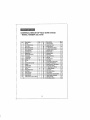
UNIVERSAL BENCH TOP TOOL WORK STAND
- MODEL
NUMBER
320.19730
No.
t
Description
M8 Nut
2
3
M8 X 38rnm Screw
inner Tube
8
4
27
2.8
Upper Inner Tube
Nut End Cover .....
MBX 32ram Se_'e,,v
M5 X 14mm Screw
4
6
29
30
"×" Steel Brackel (Rear}
Protection Jacket el Nu[
1
2
3I
32
Stopping Tube 1
Plastic Clamp
1
I
4
5
_
6
7 .....
................
Qty.
.....................6
Gemel Bracket
Connection rod
.......
..... Slidfng Bush
9
Moving Sleel Board
10
FixfngBush
..........
11
Loskin_ Block........
i2
Lockln_Nut
13
M8 Nut
14
Pin
......................
15
Puli Handle Assembiy
16
Washer
1
1
E .
No,
26
,
Description
Moving Handle
.....
..1.......
2..
2
33
Slopping lube 2
....
! .........
1
34
End Cover
2
2 .......,. 35....,. Tube of Pull Rod
1
2
36
Pulf Red
1
;
i
, 2 ........................
37
, Pee_HenCever.
4 .....
t2
38 ...........
Short Pillar
4
t
39 ..............
pre§s Board of Shod Pillar
4
!
t
40
Spring of Press Board ................ 4.
8
4t
Spring Cover or Press Board
4
17
H_nd_e
Spr_ng,"iii..................
t
18
19
20
21
22
23
24
Stel_ Brac.k_.!.....
M5 Nut
t ........... 43
!,1 ..............
44
"×" Steaf Bracket (Front1
"X _'Pfastic Bracket
FixingStoat Board
End Cover
t .......................
45
2
46
Outer Tube
M5 X 12ram Screw
25
Oty.
! 1
._2
M4X _Sn_rn
Scow
LB
1
,4.
4
{ 5
OuZel' Putl Rod............................ 1
47
.... Fop_Cush!qn ............................
Nylon Bracket .............
_nner Pull rod
Liltla B_ackel at Gemel Board
,18
49
50
Upper Support Leg Assembly
Lower Support Assembiy
RallerAssembl!/
1
2
2 ....
51
M5 X 42ram Screw
g
4
1
1
19
...........
2
Get it fixed, at your home or ours!
Your Home
For repair - in your I_ome -of all major brand appliances,
lawn and garden equipment, or heabng and cooli_ systems
no matter who made Jr, no matter who sold it!
For the replacement pa|ts, accessories and
owne_ s rnanv_Js that you need to do-i[-youfself
For Sears professional installation of home appliances
and items hke garage door openers and water heaters
1,-800_4-1_-HOME
_'' _ytifne,
(l*BO0, 46£-46!}31
(U £A
d_y or nigi_l
and Can_d_
Qur Home
For repair of carry-in p_uducts like vacuums, fawn equipment.
and electronics cal! or go onqine [or thenearest
Sears Parts and Repair Center.
t--,900-488.,1222
Anylime
day or P,igh| (tJS
A rally)
To purchase a p_ete,_ion ag[eeme,',, (U S.A )
or main,enance agreemen, (C_.nada) on a pr_tcL serviced by Sears:
1-80_827-6655
{u,sA)
Para p-_f_rser_4abde reparacbn
a domic_io, y F_ ordenar Fezas.
1..888--SU-HOGAR:';'
(1_8B-78-I-6427)
1.800-3$!4G65
[Can_)
Au Car_da Fourser,4ce en rran,_a_s:
1.SOO.LE4=OYER:,','
(1.800-532_693T1