1
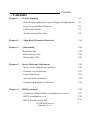
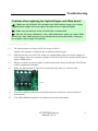
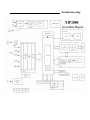
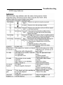
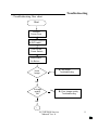
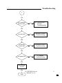
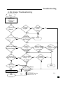
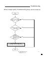
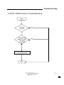
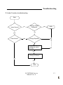
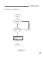
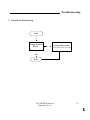
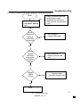
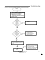
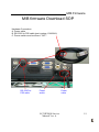
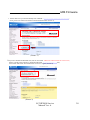
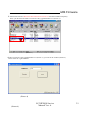
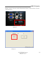
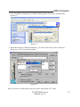
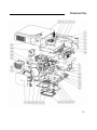
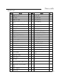
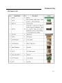
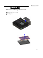
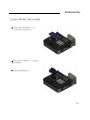
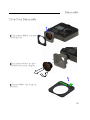
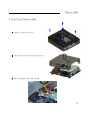
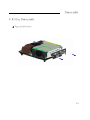
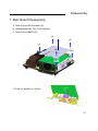
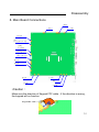
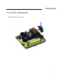
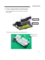
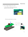
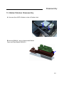
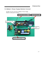
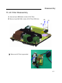
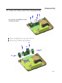
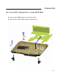
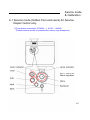
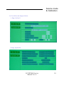
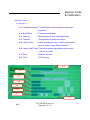
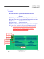
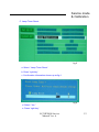
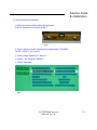
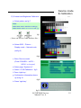
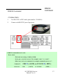
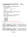
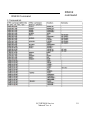
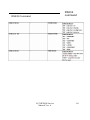
LC-XIP2000
LCD projector
Service Manual
Version A
Feb. 14, 2007
LC-XIP2000 Service
Manual Ver. A
1
Revision History
Project
Approval
date
Leader
Description
LC-XIP2000 Service
Manual Ver. A
Device
changed
Comment
2
Contents
- Contents
Chapter 1 :
Trouble Shooting
P4
- Caution when replacing the Optical Engine and Main Board
P5
- Projector system Block Diagram
P6
- LED Lamp Indicator
P7
- Trouble shooting flow chart
P8
Chapter 2 :
- Main Board Firmware Download
P18
Chapter 3 :
- Disassembly
P24
-Exploded Chart
-Mechanical part lists
P25
P26
- Disassembly SOP
P28
Service Mode and Adjustment
P48
- Service mode (hidden from end users)
P49
- Firmware version checking
P51
- Lamp Timer Reset
P53
- Auto Keystone Calibration
P54
- Contrast and Brightness Calibration
P55
RS232 command
P56
- Connection (What if RS232 command doesn’t work?)
- RS232 command list ver.5
P57
P58
P61
Chapter 4 :
Chapter 4 :
- RS232 Remote_control Pad
LC-XIP2000 Service
Manual Ver. A
3
Chapter 1
Trouble shooting
LC-XIP2000 Service
Manual Ver. A
4
Troubleshooting
Cautions when replacing the Optical Engine and Main board :
◎ 1. Make sure the IC# 24LC256 on main board U619 location always goes with its
original optical engine when you replace the main board or Optical Engine.
◎ 2. Make sure the direction of the IC# 24LC256 on main board.
◎ 3. Execute “Keystone calibration ” and “C&B calibration” when you replace Main
board every time. Otherwise the screen will become keystone distortion or miss gray
level. (please refer to page P45 and P46 )
-----------------------------1.1
The color parameter is kept in 24LC256( locate at U619),
and the color parameter is different due to different optical engine.
1.2
EDI will provide a new 24LC256 with a new optical engine when you need to change an
optical engine. The color parameter settings of the 24LC256 have to match with the optical
engine in EDI factory.
1.3
When you replace an optical engine or main board, please always confirm the 24LC256 go
with its original optical engine.
2.1
Make sure the direction of 24LC256 on main board, the mark (*) at the left side.
U619
3.1
Keystone calibration function is to help the projector execute the keystone function
automatically.
3.2
The C&B calibration function is to optimize the picture performance.
LC-XIP2000 Service
Manual Ver. A
5
Troubleshooting
Troubleshooting
- LED Lamp Indicator
LC-XIP2000 Service
Manual Ver. A
7
Troubleshooting
- Troubleshooting flow chart
Start
Connect
Power Core
Connect computer
& DVD cable
Turn On the
Power Switch
Press Lamp
On Button
Have
Image
No
A. No Image
Troubleshooting
Yes
Is Image
quality
OK
No
B. Poor Image quality
Troubleshooting
Yes
1
LC-XIP2000 Service
Manual Ver. A
8
Troubleshooting
1
Yes
Is the OSD&DVD
function OK?
No
C. OSD & DVD
function
Troubleshooting
Yes
Is Audio OK?
No
D.Audio Function
Troubleshooting
No
E.Remote Control
Troubleshooting
No
F. Keypad
Troubleshooting
Yes
Is Remote
Control OK?
Yes
Is Keypad OK?
Yes
No Trouble
Found
Yes
END
LC-XIP2000 Service
Manual Ver. A
9
Troubleshooting
A.No Image Troubleshooting
Start
Check LED
indicator on
keypad
Green off
Red off
Change
keypad
yes
Change
power
supply
no
no
yes
yes
Check /
change lamp
door switch
Green fast flashing
yes
Red on
no
Check /
no
change
thermal sensor
connector
yes
yes
no
Green on
Red fast flashing
END
no
Green fast flashing
Red fast flashing
yes
Check fan pin2
voltage - 5V
yes
Check / change
no
thermal switch
connector
yes
no.
(J1,J4,J5,
J6,J15)
no
Check /
no
change Lamp
/ Ballast
Change
failed fan
yes
yes
no
no
Green on
Red off
no
yes
END
Change Main Board,
no
No trouble found
END
Yes
but keep the same
24LC256
LC-XIP2000 Service
Manual Ver. A
10
Troubleshooting
B.Poor Image quality Troubleshooting (flicker, discolor, streak..etc)
Start
Press " Auto" key &
" reset all " on OSD
yes
no
Change computer /
DVD cable
yes
no
Change
Main board, but
keep the same
24LC256
yes
no
Change Optical Engine and
24LC256 (that of the new Optical Engine)
END
LC-XIP2000 Service
Manual Ver. A
11
Troubleshooting
C.DVD / OSD Function Troubleshooting
Start
Re-flash
firmware
yes
no
Change Main
board, but keep
the same
24LC256
yes
no
No trouble found
END
LC-XIP2000 Service
Manual Ver. A
12
Troubleshooting
D. Audio Function troubleshooting
Start
Have Sound?
Change Cable/
Connector
no
END
no
yes
Have Noise?
yes
yes
Change Speaker
yes
no
Change Main Board,
but keep the same
24LC256
yes
no
Change IO Board
no
yes
END
LC-XIP2000 Service
Manual Ver. A
13
Troubleshooting
E. Remote Control troubleshooting
Start
Replace the
Battery
yes
no
Change New
Remote Control
yes
END
no
Change Main board,
but keep the same
24LC256
END
LC-XIP2000 Service
Manual Ver. A
14
Troubleshooting
F. Keypad troubleshooting
Start
Change Keypad
Board
no
Change Main board,
but keep the same 24LC256
yes
END
LC-XIP2000 Service
Manual Ver. A
15
H. Built-in interactive smart function troubleshooting-1
Start
No
When “LightPen
not found” shows
up?
Troubleshooting
Refer to Owner’s Manual
and properly install
Software and Hardware.
And systems requirements
met?
Yes
Check
projector’s
external
USB cable
connection
No
Re-connect or
replace USB cable
Yes
Check
internal
M/B USB
connection
to CMOS
module
No
Re-connect or
replace internal USB
wire
Yes
Replace
CMOS
module
No
Replace/repair
projector’s main board
Yes
END
LC-XIP2000 Service
Manual Ver. A
16
I. Built-in interactive smart function troubleshooting-2
Troubleshooting
Start
* Can’t make the green cross
target turn into black in
calibration procedure?
* Light pen or Baton (Pointer)
doesn’t work.
Check if
CMOS
sensor
window
clean or
not
Clean it
No
Yes
Check if
battery
contact OK
or battery
low
Clean battery’s
contact terminal or
replace battery
No
Yes
Replace Light Pen or Baton
unit and see if it works or
not
Yes
No
Refer to Owner’s Manual
for Software and
Hardware installation tips
and systems required
END
LC-XIP2000 Service
Manual Ver. A
17
Chapter 2
M/B Firmware
Download
LC-XIP2000 Service
Manual Ver. A
18
M/B Firmware
M/B firmware Download SOP
Hardware Connection:
A. Power cable
B. RS-232C-to-PS2 cable (part number: 13660016)
C. Power switch must be turned " OFF".
RS-232C-toPS2 cable
Power
switch
LC-XIP2000 Service
Manual Ver. A
Power
cable
19
M/B Firmware
1. Please make sure your PC had already been installed ” Microsoft .NET Framework Version 2.0 “.
If not, please visit Microsoft website to download and install. (Picture 1).
(Picture 1)
2. If you are WinXP and Win2000 user, but can not install ”Microsoft .NET Framework Version 2.0”,
Please visit Microsoft website to download and install ”Windows Installer 3.1”first,
then install “Microsoft .NET Framework Version 2.0 ”again. (Picture 2)
(Picture 2)
LC-XIP2000 Service
Manual Ver. A
20
M/B Firmware
3. Please make sure the ”Microsoft .NET Framework Version 2.0” had been installed completely.
Then, open the firmware folder. Execute the “ED_UpgradeFlasher.exe “(Picture 3).
(Picture 3)
4. After execute the “ED_UpgradeFlasher.exe “(Picture 3), you will see the window (Picture 4).
Please select the right COM Port.
(Picture 4)
(Picture 4)
LC-XIP2000 Service
Manual Ver. A
21
M/B Firmware
5. Please “ turn on” the power switch of the projector (Picture 5), and execute the “Execute”
button (Picture 6).
(Picture 5)
(Picture 6)
LC-XIP2000 Service
Manual Ver. A
22
M/B Firmware
6. The PixelWorks ImageProcessor SDK FlasherUpgrader will process automatically
(Picture 7).
(Picture 7)
7. When the firmware is flashed completely, you will see the below picture (Picture 8).
Please press “OK” to quit this program.
(Picture 8)
8. If you need to re-flash another projector, please repeat Item 4 to 7 steps.
LC-XIP2000 Service
Manual Ver. A
23
Chapter 3
Disassembly
24
Disassembly
25
Disassembly
- Parts List
No.
Name
Q't
No.
Name
y
1
26 Cover SW
Q'
ty
1
1
Mylar AC PF
2
AC filter
1
27
Lens adaptor
1
3
Plate AC Filter
1
28
Case BTM A
1
4
Optical engine assy. with LCD
panel
1
29
Lens Housing
1
5
Cover bottom MB EMI
1
30
Conversion lens
1
6
MB plate
1
31
Lens Cover
1
7
IO case
1
32
Adjust foot A
1
8
Ballast
1
33
CMOS Front Panel
1
9
Ballast case
1
34
Case Inlet Cover MO2
1
10 Plate ballast EMI MO1
1
35
Case Inlet Press A
1
11 FRPP
1
36
Cover lamp
1
12 Power supply
1
37
Card holder
1
13 Power case
1
38
Rubber foot back
1
14 IR B assy.
1
39
Case BTM EMI
1
15 Main Board
1
40
Case flow in
1
16 Cover top MB EMI
1
41
Pronpet Flow Base
1
17 Keypad board
1
42
Case Air Panel
1
18 Case keypad
1
43
Blower fan 1 toto TYF450
LJ05
1
19 Plate MB GND
1
44
20 Case top A
1
45
21 IR Filter
1
46
22 Inlet fan AD0612 HB-A72GL
1
47
Blower fan 2 toto TYF400
LJ09
1
48
24 Assy. Exhaust
1
49
25 IR receiver
1
50
23
26
Disassembly
- Screws List
27
Disassembly
Disassembly SOP
1.Bottom Cover Sponge Disassembly
A. Push Case Inlet Cover out of slot
B.Take Sponge off
28
Disassembly
2.Lamp Module Disassembly
A. .Take off Screw BM3x8 1 pcs
and remove Lamp Cover
B.Take off Screw BM3x12 2 pcs from
Lamp Module
C.Pull Lamp Module out
29
Disassembly
3.Top Cover Disassembly
A.Take off Screw BM3x8 2 pcs from
Conversion cover
B.Take off Screw M3x8 4 pcs from
Conversion cover reverse clockwise
C. Unscrew BM3x8 1 pcs to take off
IR receiver
30
Disassembly
4.Top Cover Disassembly
A. Unscrew 5 pcs M3*8 screws
B. Turn projector around and take top case off
C. Pull out Keypad FPC cable carefully
31
Disassembly
5. Key Pad Disassembly
A. Take off 4 M3*5 screws
32
Disassembly
6. IO Case Disassembly
A. Take off 2 M3*8 screws
33
Disassembly
7. Main Board Disassembly
A. Take off 4 pcs M3*6+washer (A)
B. Unassembled EMI_Top_Cover carefully.
C. Take off 2 pcs BM3*8 (B)
(A)
(A)
(A)
(A)
(B)
(B)
C.Take out speaker (no screw)
34
Disassembly
8. Main Board Connections
Power
Lamp
IR1
Fan EP
SW
(Lamp door switch)
Battery
(Optional)
KPD( keypad)
THA (Thermal)
Fan EY
Fan EW
Fan FX
Fan EV
CMOS
IR2
Speaker
•Caution :
KP
Keypad FPC cable
D
Make sure the direction of Keypad FPC cable , if the direction is wrong ,
the keypad will no function
35
Disassembly
9. M/B Plate, IR Assy Disassembly
A. Unscrew 1pcs M3*8(A)
B. Unscrew 1pcs BM3*8(B)
C. Unscrew 6pcs HEX Head M2.8*7(C) to take of M/B plate
D. Carefully take apart EMI_Bottom_Cover to avoid dropping it down.
E. Unscrew 1pcs M3*6+Washer to take off IR assy.
(A)
(C)
(B)
36
Disassembly
10. Inlet Fan Disassembly
A. Take off Fan (no screws).
37
Disassembly
11. Power Supply Module Disassembly
A.Unscrew BM3x8 6 pcs to take off Power and Ballast
Module holder
Ballast module
Power module
B. Remove cover protection sheet as below picture
AC Filter (COM1)
38
Disassembly
12. Power Supply Module Disassembly
C. Take off COM1 and COM2 Jack by pressing and
pulling out the hook as picture below
D.Take Power Module holder out of 4 hooks
39
Disassembly
13. Ballast Module Disassembly
A. Unscrew 2pcs M3*5+Washer to take off ballast Jack
B.Unscrew BM3x8 1 pcs to disassembe Ballast
Case and Plate Ballast EMI MO1
40
Disassembly
14. Ballast / Power Supply Module Connect
A. Make sure the connection of Ballast / Power Supply
Module to other parts is correct
To Lamp connector of PCBA
To Jack of Lamp Holder
Power Module to Ballast
Module(COM2)
AC Filter to Power
Module(COM1)
To Power connector of PCBA
41
Disassembly
15. AC Filter Disassembly
A. Unscrew 2pcs BM3x8(A) to take off AC Filter.
B. Remove 1pcs M4*6(B) to take off AC Filter GND wire.
(B)
(A)
(A)
B. Make sure AC filter is grounded
42
Disassembly
16.Take out Exhaust Duct
A.Unscrew BM3x8 2 pcs to take off Exhaust Duct module
as below picture
43
Disassembly
17.Take out Optical Engine Module
A. Unscrew M3x6 4 pcs to take off Optical Engine module
as below picture
44
Disassembly
18.Take out Plate_MB_GND
A. Unscrew BM3x8 to disassemble Plate_MB_GND part.
45
Disassembly
19. Case Air Panel and Flow Disassembly
A. Unscrew 5 pcs BM3*8 to take
off Case Air Panel
B. Unscrew 3pcs BM3*8(A) to take off Case Flow IN
C. Unscrew 4pcs Z3*30(B) to take off Blowers
(A)
(A)
(A)
(B)
(B)
46
Disassembly
20. Cover SW, Adjust foot A, Case BTM EMI
A. Unscrew 2pcs BM2*10(A) to take off Cover SW
B. Unscrew 2pcs M2.6*18(B) to take off Adjust foot A
(A)
(B)
(B)
47
Chapter 4
Service mode
and
Calibration
LC-XIP2000 Service
Manual Ver. A
48
Service mode
& Calibration
4-1 Service mode (hidden from end users) for Service
Repair Center only
I) Press button sequentially: POWER → AUTO →MENU
(Please press as quickly as possible after start-up logo disappears.)
1
fig 1
3
2
LC-XIP2000 Service
Manual Ver. A
49
Service mode
& Calibration
2) You will see the image as below:
a. Page: Set Up 01
b. Page: System Inf
LC-XIP2000 Service
Manual Ver. A
50
Service mode
& Calibration
II) Service mode :
A. Set Up 01
A-1: Firmware Version: The firmware version which used at the
projector.
A-2: Build Date
: Firmware build date
A-3: Temp01
: Temperature of inlet ventilation area
A-4: Temp02
: Temperature of projector lamp
A-5: Lamp Timer
: Lamp operation hours. It will be reset after
execute Lamp Timer Reset function.
A-6: Lamp Total Timer: The total system operation hours which
can not be reset.
A-7: GVer
: Gamma Version
A-8: PVer
: PIC Version
A-1
A-2
A-3
A-4
A-5
A-6
A-7
A-8
fig 2
LC-XIP2000 Service
Manual Ver. A
51
Service mode
& Calibration
II) Service mode :
B. System Inf
B-1: C&B Calibration: Contrast and Brightness calibration
adjustment.
projector.
B-2: A V Keystone Default: Auto Vertical Keystone function reset
B-3: Lamp Timer reset: To reset lamp timer when replace new lamp.
B-4: Gamma
: For EDI internal used only
B-5: Panel Select
: Panel manufacturer
B-6: DriverBn Gamma : The current input signal source at projector
B-7: Lamp Timer Testing: For EDI internal testing purpose only.
PS: If you execute the” Lamp Timer Testing” function, the lamp
timer will show “1999” operation hours and the alarm
system will remind you to replace lamp.
B-1
B-2
B-3
B-4
B-5
B-6
B-7
fig 2
LC-XIP2000 Service
Manual Ver. A
52
Service mode
& Calibration
C. Lamp Timer Reset:
fig 3
a. Select “Lamp Timer Reset “
b. Press “right key “
c. Confirmation information shows up as fig 4
fig 4
d. Select “Yes ”
e. Press “right key “
LC-XIP2000 Service
Manual Ver. A
53
Service mode
& Calibration
D) Auto Keystone Calibration
a. Make sure the surface where the projector
is put is horizontal (no slope) as fig 5
fig 5
b. Enter “Service mode” (Press button sequentially “POWER→
AUTO→MENU “ on keypad)
c. Select page “System Inf “ as fig 6
d. Select “ AV Keystone Default “
e. Press “right key “
fig 6
LC-XIP2000 Service
Manual Ver. A
54
Service mode
& Calibration
E) Contrast and Brightness Calibration
a. Select pattern as fig 7
Note :
Model XGA: select “XGA EX17 C&B”.jpg
Model SVGA: select “SVGA EX17C&B”.jpg
fig 7
( Please ask Service Center for these files. )
b. Select OSD→ Picture→
Display mode→ Natural mode
(as fig 8)
fig 8
c. Enter “Service mode“
(Press “POWER→ AUTO→
MENU“ on keypad)
d. Select page “System Inf “
e. Select “C & B Calibration “ fig 9
f. Press “right key “
g. Confirmation information shows
up as fig 10
fig 9
h. Press “right key “
fig 10
LC-XIP2000 Service
Manual Ver. A
55
Chapter 5
RS232
Command
LC-XIP2000 Service
Manual Ver. A
56
RS232
command
RS232 Command
- Connection :
1.
Use RS-232C-to-PS2 cable (part number: 13660016)
2.
Connect with RS232C port of projector
- If RS232 command doesn’t work:
Please check
- The baud rate setting is 9600 or 19200
- Is the port you select correct? For example “com 1” or “com 2”
- Make sure you key in command, for example command “power on ”:
Correct
incorrect :
:
C00CR ( ASCII) or 43 30 30 0D ( HEX )
C00
( ASCII)
or 43 30 30
LC-XIP2000 Service
Manual Ver. A
( HEX )
57
RS232
command
RS232 Command
LC-XIP2000 Service
Manual Ver. A
58
RS232
command
RS232 Command
LC-XIP2000 Service
Manual Ver. A
59
RS232
command
RS232 Command
LC-XIP2000 Service
Manual Ver. A
60
RS232
command
- RS232 Remote_control Pad
(software part number: 51760001 )
- What if RS232 Remote_control Pad doesn’t work?
Please check
I - Make sure the version is 5.1 or greater than 5.1.
II - Make sure the code type is Type_1
III - The baud rate setting is 9600 or 19200
IV - Is the connect port you select correct? For example “com 1” or “com 2 ”
LC-XIP2000 Service
Manual Ver. A
61