1
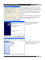
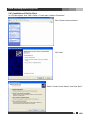
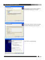
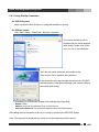
VDS Net (Integration) Installation and User’s Guide Ver 11.06.x Digital Video Security System Digital Video Recorder www.videodigitalsecurity.com VDS, INC. *All contents of this document may change without prior notice. www.videodigitalsecurity.com INDEX 1. Forward 2 2. Introduction 3 3. Installation 4 4. Using Net software 5 5 4.1.1. Site Setup 6 4.1.2. Setup Connection Mode 8 4.1.3. MISC. Configuration 9 4.1.4. IP Server Setup 9 4.1.5. Change Login Password 10 4.2. Accessing VDS Net 11 4.3. Remote Search 15 4.4. Remote Setup 18 4.5. Event Viewer 18 19 5.1. Changing Position 19 5.2. Movie Clip & Snapshot 19 5.3. Event Notification 20 5.4. Dial-Up Connection 21 4.1. DiViS Login Setup 5. Appendix 5.4.1. Installation of Dial-Up Server 21 5.4.2. Installation of Dial-Up Client 26 5.4.3. Using Dial-Up Connection 29 1 VDS www.videodigitalsecurity.com 1. Forward Previously, camera manipulation and data storing/searching were possible only on the DVR installed computer. This meant that a person must physically present in front of the specific computer for even minor administration such as checking the current status of the system. This has become a big hassle for those who must overlook many DVR systems. To overcome these difficulties, VDS Net has been introduced. With VDS Net, you can now enjoy all the functions of a VDS system anytime, any remote location by connecting to the main server computer over modem, LAN, or Internet. The functions include checking the system status, searching the stored data, and even changing the user settings and the recording schedule. The ability to be able to perform total control from any place any time is what DiViS Net makes by introducing Network Security Program for the next generation. For any question you have, please contact to the following address. When you are sending your concerned matter, please include your country and phone number. www.videodigitalsecurity.com 2 VDS www.videodigitalsecurity.com 2. Introduction • Support TCP/IP. Support communication protocol to log in VDS DVR. • Real-time Monitoring of DiViS motion pictures Log in VDS Net and monitor all VDS DVR system images in real time. • Flexible relocation of displayed channels Displayed channel can be moved to desired location of the screen by simple drag and drop. • Searching and Recording DiViS data Various feature for Search and Recording, and even bring data to save it on the local computer. • Audio Search Recorded audio data can be retrieved VDS Net software. • Two-way Voice Communications VDS Net provides voice communication capabilities with the VDS DVR system. • PAN/TILT/ZOOM/FOCUS remote control PTZ Controls can be attained by manipulating DiViS Net program. • Manipulate DiViS DVR Settings Ability to change settings of VDS DVR system from VDS Net, such as enable / disable of cameras, change recording schedule, and change setting of sensors. • Remote Notify function (Automatically message alert sent from DiViS DVR) When VDS DVR System detects motion or sensor trigger, it notifies its event and automatically turns on VDS Net (while VDS Net is minimized). Also can be verified from event viewer • Analyzing Event Log VDS Net can receive and record events notified from VDS DVR System, and the event viewer will directly connect to the VDS DVR System to retrieve data. - VDS CAP, VDS MPG, VDS LIVCAP, and VDS ACAP are all supported. 3 VDS - www.videodigitalsecurity.com 3. Installation Click 'Setup.exe' and follow the procedure. After installation, following folder will be created in the Start menu. DiViS Net: VDS Net program AVI Viewer: Program to view video clips recorded at the local storage. Event Viewer: Program to view event log. Uninstall: VDS Net remove program 4 VDS www.videodigitalsecurity.com 4. Using Net Software 4.1. DiViS Login Setup Run VDS Net. Then following dialogue box appears, which asks for ID of VDS Net. • Login: ID / password are for the authorized manager who controls the local network system. Note that login name and password here is for VDS Net program. It is different login and password than that of DVR–main. • New: Create a new user (management) who wants to have the new network system. • Edit: Change the existing information of registered user. • Cancel: Exit without change. • Minimized screen: Make the tray icon of this network program. Used for Remote Notify. For the first time, or to add a new user, click “New” and type the information of user as follows. • Login name: ID for a VDS Net program user. • Password: Password for Login. • Confirm P/W: Reconfirm the password Note: The user created here is for local manager, which is not related the user(s) registered at VDS DVR System. After you input the above information, click “OK”. Then, “Add, Delete and Edit site information” screen will be appeared. 5 VDS www.videodigitalsecurity.com 4.1.1. Site Setup • New: Add new site information. • Delete: Delete the registered site. • Save: Record any changes made. • : allows users to sort the list of sites. Select a site and press either one of the arrow buttons to move an entry up/down. • Apply: Apply any changed setting and close the Config / Settings. • Close: Close Config / Settings without applying changes Note: Any changes will be effective once the Save button is clicked. Close or Apply without Save will loose all changed information. The same site name can not be registered twice. Click “New” to add a new site information. • Site name: Assign system’s name or site name. In the use of IP Server, put the Code No. , The code for Server side can be set at “system->Use IP Server” in the VDS DVR Setting. Note: This code is also necessary for Remote notify. • Method: Select “TCP/IP” when you are using LAN, cable modem, ADSL. In case of IP Server, select “SERVER”. • Address: Assign IP address of system or IP address in use of IP Server. • User name: Enter ID, registered in VDS DVR System. 6 VDS www.videodigitalsecurity.com • Password: Enter password, registered in VDS DVR System 7 VDS www.videodigitalsecurity.com • Port (Properties): Set the port No, which was stored in accordance with “ Appendix > DVR Management > Detail setting” in DVR main/ User’s Guide. It is recommended to use the default data stored in DVR program unless it is necessary to use others. Click “OK” to finish a new site setting, then the added site will be listed as following. In order to edit the site information already stored, double click on the site name to change the data. “Save” must be clicked to take effect. 8 VDS www.videodigitalsecurity.com 4.1.2. Setup Connection Mode •Single: Check and select one of registered sites to access one site of DVR main. •Multiple: Check to access multi-sites upon log in. Connection must be defined as following. • Site name: select a site to connect. • Camera number(s): Choose a camera number, all, or partial -All: Choose to display all available cameras sequentially from the selected site. -Partial: Choose to display multiple cameras from the site. Number of cameras must be assigned. For example, the position 8 will display camera 1, 3, 6, 9, and 14 sequentially from site name Office. “Save” must be clicked to take effect. 9 VDS www.videodigitalsecurity.com 4.1.3. MISC. Configuration •AVI Path: Assigns the path to store video clips recorded while monitoring. •Log Path: Assigns the path to store the log file. •Max Size: Assigns the maximum size of the log file. “Save” must be clicked to take effect. 4.1.4. IP Server Setup •Use IP Server: Enables to use IP Server if checked. •Server: IP address of the IP Server. •Code: Assigns unique code name to be registered at the IP Server. Code must be named less than 10 digits, using case sensitive alpha-numeric characters. •Interval: Selects the time interval to notify current IP address to the IP Server. “Save” must be clicked to take effect. 10 VDS www.videodigitalsecurity.com 4.1.5. Change Login Password •Old Password: Enter current password •New Password: Enter new password •Confirm Password: Confirm new password. “Save” must be clicked to take effect. 11 VDS www.videodigitalsecurity.com 4.2. Accessing VDS Net Type login and password and click “LOGIN”. : Minimize VDS Net software in the system tray. Click at right bottom corner will bring the full window. • Date/Time: indicates the time and date of the location of DVR Net • Login name: User ID currently logged in with. • Event Information: It is the place to indicate any of event notification from connected site(s). To receive notification, “Remote notification of events” must be checked on DVR main. • Transfer Status: This is indicating the connecting speed as bench mark only. : Refresh the connection. 12 VDS www.videodigitalsecurity.com Press “CAMERA” to control the PTZ. : PTZ cameras connected to DiViS DVR System can be controlled from DiViS Net. The arrow buttons will move the camera in the direction of the arrow, and the ZOOM, FOCUS buttons will manipulate the camera accordingly. However, only user with permission can control the PTZ setting. The number in the middle circle indicates the camera number being controlled, and the push of top or bottom arrow button makes the selection of the camera. : When the PTZ camera supports preset function and tour, this control is available at DiViS Net. However, settings of preset and tour must be made at VDS DVR System. And No. of available preset points are depending on the camera’s feature. Press “IMAGE” to show image control. : Adjusts the image quality such as Brightness, Contrast, Saturation and Hue by pushing the arrow buttons. Press “RATE” to adjust resolution and compression rate . : Compression Rate can be adjusted between 10 ~ 90 to enhance the transmission speed (* for default compression rate). Lower value will provide faster transmission. Resolution can be selected among 1/2, 1/4, or 1/8 (* for default resolution), and lower resolution provides faster transmission speed. Compression rate and resolution adjusted here are not changing actual resolution and compression rate recorded on the server. Note: this section cannot be applied to MPG series products. 13 VDS www.videodigitalsecurity.com Press “MISC” to contol following functions. • Switching (SLOW / FAST): Adjust switching interval slower or faster when the channel is displaying multiple cameras by switching (Applicable for multi connection only). • Position Number: Displays the position number on the image. • Site Name: Displays the site information on the image. • Camera Number: Displays the camera number on the image. • Camera Name: Displays the camera name assigned at the server. • Date / Time: Displays date and time from the server. • POS Data: Displays POS data if available. • Event Mute: Mutes the beep sound by the event notification. It also disables the popup by event notification while minimized. : Displays the position number, which is currently selected. All adjustments and/or contols are applied to the camera on this position. : Shows the event list, which contains log of events notified from server(s). Double clicking on the event will popup the search window to retreive data immediately. : Open the “Config / Settings” Window (Refer to 4.1. VDS Login Setup for detail). : Records all displayed channels. Each channel will be recorded in MP4 format at the AVI Path assigned from “Config / Settings” => “MISC Configuration”. The position with enabled switching camera will not be recorded. Switching camera must be disabled when the desired camera is on, before start recording. : Search recorded data from server. Multiple search windows can be initiated simultaneously to search multiple servers at the same time. : Adjusts setting of VDS DVR System from DiViS Net. 14 VDS www.videodigitalsecurity.com : Changes display mode to 1, 4, 6, 9, 10, 16, or 36 split screen. : Displays next set of view. : Enlarges the image size from single channel display mode. : Reduces the image size from single channel display mode. : Enlarges the VDS Net screen with minimal control buttons. : Enables on-screen PTZ Control. If enabled on the PTZ camera connected, Using mouse, left click and drag on the screen to pan and tilt the camera, and scroll to zoom in and out : Displays status of current screen mode. Pink color indicates positions currently on-screen. : To control voice communications between VDS Net and VDS DVR System. For this function, "Sound Recording" of Settings in VDS DVR System must be checked. The functions of four taps are “Send Voice” / “Receive sound” / “Send and receive voice” / “cancel”, from the left. : Displays status of Relay on VDS DVR System. Relay can be activated / deactivated by clicking on the buttons. : Click this to exit from DiViS Net. 15 VDS www.videodigitalsecurity.com 4.3. Remote Search Search data of VDS DVR System from remote location using DiViS Net. : Click the remote search button to start. The window on the left will show up with list of registered sites Select the site to search, and click “OK” to start search. 16 VDS www.videodigitalsecurity.com : The calendar allows the user to choose the specific date in which to search through. Days with stored recorded data will be highlighted red. 17 VDS www.videodigitalsecurity.com : Change between search tools and image control tools. : Buttons in upper line works for fast rewind (left directional arrow) and fast forward (right directional arrow). Buttons in middle line activate the normal playing back in forward and reverse but the speed can be adjusted by controlling ( - ),( + ) tap on the top. The buttons in lower line give playback frame by frame, forward or reverse. : Image Tools allow the user to adjust image properties to enhance the image quality. Adjustments are not effecting to the original image recorded. Click on Cancel to go back to the original image. Zoom Search: It is possible to zoom in, up to x3, to the desired area using right click of the mouse while, or before searching (Available only at single channel search) : hides the time information. : Select one of the split image profiles for viewing the images. : These taps give the enlarged screen by (+) or return to small screen by (-). : The camera number is shown vertically on the right and hour on bottom horizontally, and minute on top horizontally. The searching point can be selected by clicking the camera number, hour, and minute (shown in red). : In above picture, selection of camera can be done by clicking these buttons, scrolling camera group as 4 camera in a group, namely 1~4, 5~8, 9~12, 13~16 18 VDS www.videodigitalsecurity.com : The camera icon indicates camera mode. Clicking the icon will toggle to sound search mode to retrieve recorded sound with image. While searching multiple channel, selected camera for audio playback will be indicated with yellow caption as shown below/ : Click "Save As" to save the current image, jpg format. : Print the image currently on display. : Save images as a movie clip, MP4 format. : Initiate “Smart Search” feature shown below. Note: Please refer to the VDS DVR manual for detail information about this feature. Motion Sensitivity may be different than running this feature from DiViS DVR (server) and the result might differ even if the search is performed under the same condition. : Exit Search. 19 VDS www.videodigitalsecurity.com 20 VDS www.videodigitalsecurity.com 4.4. Remote Setup : Allow user to change the configuration of VDS DVR System from DiViS Net. The following screen will allow the user to select the site. Select the site and click “OK” Changes will be applied to the selected VDS DVR System. Some of setting are not accessible from the DiViS Net. Note: For further setting guide, please refer to 5.Configuration of “Installation and User’s Guide” for DiViS DVR System. 4.5. Event Viewer Event Viewer allows user to review the event log of Net software. It also contains all event record notified by VDS DVR System. Please refer to the “5.3. System - Allow remote connections” on Installation and User’s Guide to set remote notification. : opens the following Event Viewer window. Events can be reviewed and/or searched by categories. Double clicking on a recorded event under Motion and Sensor will load a search popup window, which enables to playback instantly, as shown below. : Popup search initiated from Event Viewer. 21 VDS www.videodigitalsecurity.com 5. Appendix 5.1. Changing Position At the connection of Net software, connected cameras will be positioned in order of camera numbers. It is possible to relocate the camera position to the desired location by left click on the image that needs to be relocated, drag it to the new position, and release the mouse button. 5.2. Movie Clip & Snapshot Either movie clip or snapshot can be created while monitoring. Right click on the desired position and select “Save as Movie Clip” or “Save as Snapshot. Save as Movie Clip: check to create mp4 format movie clip until unchecked. Recording will be automatically finished when Net software is minimized. Recorded file will be stored at the location assigned from MISC. Configuration, AVI Path. Save as Snapshot: select to capture the image. It will bring up a snapshot window with a captured image, and the image can be saved as a jpg format file by double clicking on the snapshot window. 22 VDS www.videodigitalsecurity.com 5.3. Event Notification Event notification allows VDS Net users to receive notification from DiViS DVR System when any event occurs, such as motion and/or sensor detection. In order to activate, following settings are required at the DVR Main. Open System Setting from the VDS DVR System to configure settings. Check “Allow remote connections” and open properties. Check “Remote Notification of events”, and select the method. In IP/Code column, enter IP address or Code depending on the method selected. Note: The code shall be same as the one entered in “Code” at 4.1.3. IP Server Setup From “Color & motion” of “Camera Setup”, check “Detective motion – Notification”. Click on “Properties”, and check “Remote Notify” to send notifications when an event occurs. Check “Use Notify Schedule” to utilize the schedule to notify the VDS Net. If selected, notification schesule on the folloing page must be configured. 23 VDS www.videodigitalsecurity.com Set up “Notify scheduling” in “Scheduling” of “Camera Setup”. When event notification is completely set, Net software will display and store the event information into the log file, which can be retreived and searched by the Event Viewer. Also it will allow to restore the Net software, if any event occurred and notified while Net software is minimized. The VDS Net may be minimized, but must be running in order to receive the notification. The icon will be placed on the system tray when it is minimized. 5.4. Dial-Up Connection In order to connect to the VDS DVR System through regular phone connection, both VDS DVR System and Net system need to be equipped with modem, and Dial-Up Server / Client must be configured. The following instruction is based on the Windows XP environment. 5.4.1. Installation of Dial-Up Server On VDS DVR System, click “Start > Control panel > Network Connections.” Click “Create a new connection.” 24 VDS www.videodigitalsecurity.com Click ‘Next’. Select “Set up an advanced connection”, and Click “Next”. Check “Accept incoming connection” and Click “Next”. 25 VDS www.videodigitalsecurity.com Select a proper modem from device list, and click “Next” Select “Do not allow virtual private connections”, and click “Next”. Click “Add” to add a new user. The user must be created to allow connection to the VDS DVR System. 26 VDS www.videodigitalsecurity.com Fill out the user information and click “OK”. This user information must be used at the Dial-Up Client, which will be discussed on the next chapter. Note: The “Allowed User” means “RAS User” who can access the Dial-Up server from Dial-Up Client. After a user created, make sure to check the user created, and click “Next”. Select “Internet Protocol TCP/IP” and click ‘Properties’. 27 VDS www.videodigitalsecurity.com Check “Allow callers to access my local area network”. In TCP/IP address assignment, check “Specify TCP/IP addresses”, and fill out from and to IP address as shown in picture. It is strongly recommended to use as it is shown. Click “OK”, and click “Next” at the Networking Components. When the connection established successfully, ‘From’ IP will be the virtual IP of the server, VDS DVR System, and ‘To’ IP will be assigned to the client. Specify the connection name and click “Finish”. Any name may be used for connection name. Upon completion of Network Connection Wizard, the new connection icon will be located in Network Connection. 28 VDS www.videodigitalsecurity.com 5.4.2. Installation of Dial-Up Client On VDS Net system, click “Start > Setup > Control pad > Network Connection.” Click “Create a new connection.” Click ‘Next’. Select “Connect to the Internet”, and Click “Next”. 29 VDS www.videodigitalsecurity.com Select “Set up my connection manually”, and Click “Next”. Select “Connect using a dial-up modem”, and Click “Next”. Set ISP Name as you want, and Click “Next”. 30 VDS www.videodigitalsecurity.com Enter the phone number which is assigned to the VDS DVR System, and Click “Next”. Enter the user information, which was created on the VDS DVR System, and Click “Next”. Click “Finish” to complete setting. 31 VDS www.videodigitalsecurity.com 5.4.3. Using Dial-Up Connection • On VDS DVR system Make sure that the Dial-Up Server is configured and Main is running. • On VDS Net system, Click “Start > Setup > Control pad > Network Connection.” The icon for the Dial-up will be displayed with the name assigned while setting. Double click on the icon. It is ‘dvr’ on the left picture. Verify the user name, password, and number to dial. Then click on ‘Dial’ to establish the connection. If the connection fails, check modem drivers on both VDS DVR and Net systems, under Device Manager, and check the Dial-up server and client setting. If connected, run VDS Net and register a site with following information. Method: TCP/IP Address: the virtual IP registered at ‘From’ in Dial-up server. Username & Password: user information registered at the DiViS DVR System. After setting the site information as above, it is ready to connect to the VDS DVR System. Note: The image will be displayed very slowly due to the limited transmission speed. 32 VDS