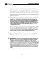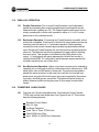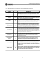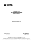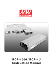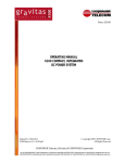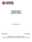
1
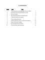
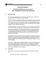
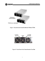
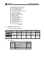
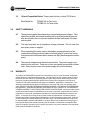
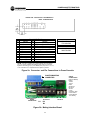
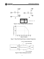
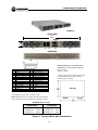
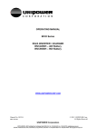
PRICE: $25.00
OPERATING MANUAL
PCM/TPCM SERIES PowerCassette®
FRONT-END SWITCHERS
www.unipowercorp.com
© 2003 UNIPOWER Corp.
All Rights Reserved
Manual No. TPCM-Man-602-4
PCM-TPCM-Man 06/11/03
UNIPOWER Corporation
NORTH AMERICA • 3900 Coral Ridge Drive, Coral Springs, Florida 33065, USA • Tel: +1 954-346-2442 • Fax: +1 954-340-7901 • [email protected]
EUROPE • Parkland Business Centre, Chartwell Road, Lancing BN15 8UE, ENGLAND • Tel: +44(0)1903 768200 • Fax: +44(0)1903 764540 • [email protected]
CONTENTS
SECTION
TOPIC
PAGE
1.0
Introduction
1
2.0
PowerCassette Features
1
3.0
Summary of Product Line
3
4.0
Safety Warnings
4
5.0
Warranty
4
6.0
Unpacking and Inspection
5
7.0
Front Panel Description
5
8.0
PowerCassette Specifications
5
9.0
Description of Features and Options
8
10.0
Mechanical Specifications
9
11.0
Safety and Industry Standards
9
12.0
Operating Information
10
13.0
Parallel Operation
14
14.0
Compatible 19-Inch Racks
14
15.0
Description of Control & Supervisory Signals
19
16.0
Installation
20
17.0
Maintenance
20
18.0
PowerCassette Setup and Testing
20
19.0
Troubleshooting Guide
23
Appendix: I2C Serial Bus Operation
24
ILLUSTRATIONS
FIGURE
TITLE
PAGE
1
PowerCassette Front End Models PCM and TPCM
2
2
Front Panel of the PowerCassette Front End
2
3
IEC Input Version
6
4
Mechanical Dimensions of PowerCassette
6
5
Connectors and Pin Connections
11
6
Output Voltage Adjustment
12
7
Rated Total Output Power vs. Ambient Temperature
12
8
Remote Sensing Connection
12
9
Two-Unit Rack with Connections
15
Three-Unit Rack with Connections
16
10
POWERCASSETTE FRONT-END
OPERATING MANUAL
OPERATING MANUAL
PCM/TPCM SERIES PowerCassette®
NEXT GENERATION FRONT-END SWITCHER
1.0
INTRODUCTION
This operating manual should be read through carefully before installing and
operating the PCM/TPCM Series PowerCassette®.
The PowerCassette is an advanced-design, front-end switching power supply that
employs a unique, new architecture which permits quick factory programming of its
output. There is a high current output and a 5VDC ¼ ampere independent standby
output. Maximum continuous output power is 650, 700 or 800 watts, with available
voltages of 12, 24 or 48VDC, respectively.
The PowerCassette front-end is ultra-compact, only 1.6 inches high, 5 inches wide
and 10 inches deep, producing up to 10 watts per cubic inch power density. The
unit comes in two versions: the PCM model which is the standard, non-hot-swap
version; and the TPCM model, which is the hot-swap version with a handle and
mounting bracket with jackscrews. See Figure 1. There is also an IEC AC input
connector with switch option and a reverse air flow option. Both of these have
reduced output capability.
PowerCassette incorporates control and monitoring features including enable and
inhibit inputs, AC power fail and DC power good signals, overtemperature warning
and remote sensing. The front panel has two LED status indicators: one for AC
Power Fail and the other for DC Power Good. The output has a single-wire, current
sharing capability.
Two 19-inch, 1U-high racks are available to hold two or three PowerCassette units
connected in parallel to give up to 800 watts with 1+1 redundancy or 1600 watts
with non-redundant operation for the two-unit rack or up to 1600 watts with 2+1
redundancy or 2400 watts with non-redundant operation for the three-unit rack. The
racks feature IEC60320 AC input connections.
2.0
FEATURES
The following is a summary of the important features of the PowerCassette frontend:
u Includes Isolated 5V, ¼ A Standby Output
1
POWERCASSETTE FRONT-END
OPERATING MANUAL
PCM Series
(Chassis Mount)
TPCM Series (Hot-Swap)
Figure 1. PowerCassette Front-End Models PCM and TPCM
AC POWER
FAIL LED
DC POWER
GOOD LED
HANDLE
4
4
4
Figure 2. Front Panel of the PowerCassette Front End
2
POWERCASSETTE FRONT-END
OPERATING MANUAL
u
u
u
u
u
u
u
u
u
u
u
u
u
u
u
u
u
Hot-Swap or Chassis Mount Versions
IEC 60320 Input Option with Switch
12, 24, or 48 VDC Outputs
Integral LED Status Indicators
Up to 10 Watts/Cubic Inch Power Density
Power Factor Corrected
Low Profile: 1.6 Inches High
Single Hot-Swappable Connector
Staged Pin Lengths
ORing Diode on Output
1U, 19” Racks Hold 2 or 3 Units*
Active Current Sharing
Universal 85 to 264VAC Input
Class B EMI Input Filter
Optimized Thermal Management
No Minimum Load
Control & Monitoring Features
*TPCM Models
3.0
SUMMARY OF PRODUCT LINE
3.1
Standard & Optional Models
Delete “T” prefix to model no. for chassis mount version.
CONFIGURATION
MAX. OUTPUT
POWER
650W
700W
800W
480W
525W
600W
Standard
Rear Input/Output
Optional
Front IEC Input
OUTPUT
VOLTAGE
12VDC
24VDC
48VDC
12VDC
24VDC
48VDC
OUTPUT
CURRENT
54.2A
29.2A
16.7A
40.0A
21.9A
12.5A
INPUT
VOLTAGE
PFC
85-264VAC
85-264VAC
85-264VAC
85-264VAC
85-264VAC
85-264VAC
YES
YES
YES
YES
YES
YES
NOTE: The table does not show the independent 5V, ¼A standby output which is standard on all models.
3.2
Options
SUFFIX
CODE
R
R
Z
OPTION
OUTPUT
DERATING
Reverse Air Flow (Back to Front)
on Standard Models
Reverse Air Flow on “E” Suffix
Models
I2C Serial Data Bus
20%
3
16.6%
N/A
MODEL
NUMBER
TPCM3000
TPCM5000
TPCM7000
TPCM3000E
TPCM5000E
TPCM7000E
POWERCASSETTE FRONT-END
OPERATING MANUAL
3.3
19-Inch Compatible Racks. These racks hold two or three TPCM units.
Rack Model No.:
4.0
5.0
TPCMR1U2 for Two Units
TPCMR1U3 for Three Units
SAFETY WARNINGS
4.1
These power supplies have hazardous external and internal voltages. They
should be handled, tested and installed only by qualified technical persons
who are trained in the use of power systems and are well aware of the hazards involved.
4.2
The input terminals are at hazardous voltage potentials. Do not touch this
area when power is applied.
4.3
When operating this power supply, the chassis ground terminal must be
connected to safety ground by means of a three-wire AC power line to minimize electrical shock hazard and to ensure low EMI (electromagnetic interference).
4.4
The internal voltages are at hazardous potentials. The power supply cover
should not be removed. There are no user-serviceable components in these
units. Removing the cover of the power supply will void the warranty.
WARRANTY
All products of UNIPOWER Corporation are warranted for two (2) years from date of shipment
against defects in material and workmanship. This warranty does not extend to products which
have been opened, altered or repaired by persons other than persons authorized by the manufacturer or to products which become defective due to acts of God, negligence or the failure of
customer to fully follow instructions with respect to installation, application or maintenance. This
warranty is extended directly by the manufacturer to the buyer and is the sole warranty applicable. EXCEPT FOR THE FOREGOING EXPRESS WARRANTY, THE MANUFACTURER MAKES
NO WARRANTY, EXPRESS OR IMPLIED, INCLUDING, BUT NOT LIMITED TO, THE WARRANTY
OF MERCHANTABILITY OR FITNESS FOR A PARTICULAR PURPOSE. As the sole and exclusive
remedy under this warranty, the manufacturer, at its option, may repair or replace the non-conforming product or issue credit, provided the manufacturer’s inspection establishes the existence of a
defect. To exercise this remedy, the buyer must contact the manufacturer’s Customer Service
Department to obtain a Return Material Authorization number and shipping instructions. Products
returned without prior authorization will be returned to buyer. All products returned for repair must
be shipped freight prepaid to UNIPOWER. If the buyer fails to fully comply with the foregoing, the
buyer agrees that no other remedy (including, but not limited to, incidental or consequential damages for lost profits, lost sales, injury to person or property or any other incidental or consequential
losses) shall be available to the buyer.
4
POWERCASSETTE FRONT-END
OPERATING MANUAL
6.0
7.0
UNPACKING AND INSPECTION
6.1
This PowerCassette was carefully tested, inspected and packaged for
shipment from our factory. Upon receipt of the unit it should be carefully
unpacked and inspected for any damage in shipment.
6.2
If there is evidence of damage, do not attempt to test the unit. The freight
carrier should be notified immediately and a claim for the cost of the power
supply should be filed with the carrier for direct reimbursement. Be sure to
include the model and serial number of the damaged unit in all correspondence with the freight carrier. Also save the shipping carton and packing
material as evidence of damage for the freight carrier’s inspection.
6.3
UNIPOWER Corporation will cooperate fully in case of any shipping
damage investigation.
6.4
Always save the packing materials for later use in shipping the unit.
Never ship the power supply without proper packing.
FRONT PANEL DESCRIPTION
The front panel of the PowerCassette is shown in Figure 2. On the left top of the
panel is the AC Power Fail LED (green) and on the right top is the DC Power Good
LED (green). For the TPCM model there is a handle between the two LEDs. Also
for this model there is a mounting bracket on the right side of the front panel. This
has a jackscrew (Allen bolt) for securing the unit. Figure 3 shows the front of the IEC
input version (Option E).
8.0
POWERCASSETTE SPECIFICATIONS
Typical at 120/230VAC Line, Full Load and 25oC Unless Otherwise Noted.
OUTPUT SPECIFICATIONS
Total Output Power, Continuous, Max. .......................... 480-800 Watts
Voltage Adjustment Range, Min. .................................................... ±5%
Total Regulation1, .......................................................................... 2.0%
1
Total Regulation , Standby Supply, ............................................... 5.0%
2
Ripple & Noise, Pk-Pk ) ................................................................... 1%
Holdup Time ................................................................................. 20mS
3
Dynamic Response ) ................................................................. 300µS
Temperature Coefficient ....................................................... ±0.02%/°C
Minimum Load, Any Output ............................................................... 0A
Overload Protection ...................................................... Auto Recovery
Overvoltage Protection ............................................ Latched Shutdown
Remote Sense .................................................... Up to 0.25V Per Wire
Current Share .................................................... ±10% Full Load Rating
5
POWERCASSETTE FRONT-END
OPERATING MANUAL
Figure 3. IEC Input Version (Option E)
NOTE: The TPCM Model is shown. The PCM version does not have
handle or mounting bracket with bolt. Maximum torque on
the threaded inserts is 6 inch-pounds.
Figure 4. Mechanical Dimensions of PowerCassette
6
POWERCASSETTE FRONT-END
OPERATING MANUAL
Standby Output ................................................................ +5V, 250mA
DC Power Good Signal ........................................................ Logic Low
AC Power Fail Signal .......................................................... Logic High
Inhibit .................................................................................... Logic Low
Enable .................................................................................. Logic Low
Thermal Warning ................................................................. Logic High
INPUT SPECIFICATIONS
Input Voltage Range ............................................................ 85-264VAC
Power Factor ............................................................................. 0.99
Input Frequency .......................................................................47-63Hz
Inrush Current Limiting ...........................................................30A Peak
Input EMI Filter ....................................................... EN55022 Curve B
FCC20780 pt. 15J Curve B
Harmonic Distortion ......................................................... EN61000-3-2
Input Immunity, Conducted
Fast Transients, Line-Line ................... ±2kV (EN61000-4-4 Level 3)
Surges, Line-Line ................................ ±2kV (EN61000-4-5 Level 3)
Surges, Line-Ground ........................... ±4kV (EN61000-4-5 Level 4)
Input Protection ....................................................... Internal Fuse, 20A
GENERAL SPECIFICATIONS
4
Efficiency ) ............................................................. 75-85% at Full Load
Switching Frequency, PFC Converter ................................. 48-110kHz
Output Converter ..................... 275kHz Nominal
5
Isolation, Class I, min.
Input-Output ..................................................................... 3000VAC
Input-Ground ..................................................................... 1500VAC
Output-Ground ...................................................................... 50VDC
MTBF (Bellcore) ............................................................. 200,000 Hours
Safety Standards ........................ EN60950, UL1950, CSA22.2 No.950
ENVIRONMENTAL SPECIFICATIONS
o
Operating Temperature ........................................ 0°C to 70 C Ambient
o
o
o
Derating ............................................................ 2.5% / C, 50 C to 70 C
o
Storage Temperature .................................................... -40 C to +85oC
Cooling ......................................................... Integral Ball Bearing Fans
PHYSICAL SPECIFICATIONS
Case Material ......................................................................... Aluminum
Dimensions, Inches(mm) .................................. 1.6 H x 5.0 W x 10.0 D
(40.6 x 127 x 254)
Weight ...................................................................... 3.15 lbs. (1.43 kg.)
NOTES:
1. No load to full load, including line regulation and load regulation.
2. Whichever is greater. 20MHz bandwidth. Measure with 0.1µF ceramic and
10µF tantalum capacitors in parallel across the output.
3. <4% deviation recovering to within 1% for 25% load change.
4. Typical efficiency is at low end of range for 12V output and at high end of range
of 48V output.
5. Input-output isolation figure is for isolation components only.
100% production Hipot tested.
7
POWERCASSETTE FRONT-END
OPERATING MANUAL
9.0
DESCRIPTION OF FEATURES & OPTIONS
DESCRIPTION
FEATURE / OPTION
Power Factor Correction
Wide Range AC Input
The input current is a sine wave in-phase with the input voltage to
give a power factor of 0.99. Input current total harmonic distortion
meets EN61000-3-2.
The AC input range is continuous from 85 to 265VAC, 47-63Hz,
for worldwide operation.
EMI Input Filter
This filter suppresses conducted noise from the supply back onto
the AC line. The filter meets FCC20780 part 15J Curve B and
EN55022 Curve B.
Inrush Current Limiting
When the unit is turned on, the initial input current is limited to a
peak value of 30 amperes AC. This is accomplished by an active
current limiting circuit (not a thermistor).
Thermal Protection
If the PowerCassette overheats internally, it will automatically shut
down. The DC Power Good LED turns off. The Overtemperature
Warning goes HI and the DC Power Good signal goes HI. After a
few minutes the unit will cool down and automatically start up
again.
Current Sharing
The PowerCassette front end will automatically current share with
another identical unit. A single-wire connection provides this. The
output actively current shares with an accuracy of 10% of full load
output current for a total load of 50% to 100%.
ORing Diodes
A diode in series with the output protects the output of parallelconnected PowerCassettes. If one output fails to a short or to a
lower than normal output voltage, the other output is not affected.
Also when hot-swapping units in the rack, the diode prevents a
glitch in the output voltage while the output is still rising on the
inserted supply. The 5V, ¼A standby output also has an ORing
diode.
5V, ¼A Standby Output
This is an independent output which is not controlled by the
Enable or Inhibit inputs. This output also has an ORing diode and
can be paralled with another PowerCassette Standby Output.
Overvoltage Protection
The output is protected from overvoltage due to fault conditions in
the supply. Overvoltage protection is set at approximately 10%
above the nominal output voltage level. The result is a latched
shutdown of the supply. It is reset by cycling the AC input off and
then back on.
No Load Operation
The PowerCassette output can be operated down to zero load
while maintaining output regulation.
8
POWERCASSETTE FRONT-END
OPERATING MANUAL
DESCRIPTION
FEATURE / OPTION
Hot-Swap Connectors
The hot-swap connectors used in both the PowerCassette and
rack are specifically designed for hot-swap applications. They
have staged pin engagement for safety and optimum operation.
The ground (common) and AC pins make first contact and the
enable pin makes last contact, turning the unit on (provided it is
not “inhibited”).
Hot-Swap Operation
Hot-swap operation means that a PowerCassette can be
removed and replaced while the rack is powering the load. If the
rack is operated in a redundant mode, hot-swap replacement
will not affect the output voltage.
Output Protection
Output current limiting protects the output of the PowerCassette
from damage due to an overload or short circuit condition. This
protection is continuous, without damage, and recovery is
automatic when the overload is removed. Current limiting
begins at about 105% of rated output current.
LED Indicators
The AC Power Fail indicator is a green LED, showing that input
power is present. The DC Power Good indicator is a green LED
showing that the output voltage is present and within operating
range.
Control and Monitoring
Signals
For detailed descriptions of Enable/Inhibit, Current Share,
Remote Sense, Input Power Fail and Output Power Good
signals, see Section 15, Description of Control and Supervisory
Signals.
IEC AC Input
(Option E)
The Option E version of the PowerCassette front end has an
IEC60320 AC front input connector with a switch, and two fans.
See Figure 3. Output power is reduced as shown in the model
table.
10.0
MECHANICAL SPECIFICATIONS
The mechanical dimensions of the PowerCassette are shown in Figure 4. Please
note the maximum torque on the threaded inserts.
11.0
SAFETY AND INDUSTRY STANDARDS
11.1
The PowerCassette meets the following safety certifications:
STANDARD
AGENCY
UL1950
CSA22.2 No.950
EN60950
UL
CUL
DEMKO
9
POWERCASSETTE FRONT-END
OPERATING MANUAL
12.0
11.2
The PowerCassette is CE marked to indicate conformance to the
European Union’s Low Voltage Directive.
11.3
Input conducted EMI meets FCC20780 part 15J Curve B and EN55022
Curve B.
11.4
The input immunity, conducted, meets the following. Input fast transients, lineto-line, meet EN61000-4-4 Level 3; input surges, line-to-line, meet EN610004-5 Level 3; and input surges, line-to-ground, meet EN61000-4-5 Level 4.
OPERATING INFORMATION
12.1
Input Voltage and Connection. The PowerCassette operates off worldwide AC input voltages in the range of 85 to 264 VAC at 47 to 63 Hz. The
three-wire AC connection is made to pins 22-24 on the Positronics connector. See the connector diagram and Pin Connections table in Figure 5a.
12.2
Output Connections. The output voltage is provided on pins 1 to 6 of the
Positronics connector. Three pins (1 to 3) are connected together internally
for the +V Out; three other pins (4 to 6) are connected together internally for
the V Return.
12.3
Mating Interface Board. Figure 5b shows a mating interface board which
is available for simplifying the testing of a PCM/TPCM PowerCassette. As
shown in the photograph, provision is made for input and output connections,
and also for the control and monitoring signals.
12.4
Output Voltage. The output voltage is factory set to its nominal value to an
accuracy of ±1%. The voltage can be more accurately adjusted to a value
within a ±5% range by means of external components as shown in Figure 6.
12.5
Output Power. The maximum continuous output power is 650 watts for the
12V output, 700 watts for the 24V output, and 800 watts for the 48V output.
For the front IEC input versions (Option E) the output power is 480, 525 and
600 watts, respectively. The 5V standby output produces 1.25 watts.
The maximum output power of a PowerCassette may be drawn up to 500C
ambient temperature. Above 500C the total output power must be derated by
2.5%/0C. See Figure 7. The maximum operating ambient temperature is
700C, at which the total output power must be derated by 50%.
12.6
Output Overload Protection. The PowerCassette output is protected from
10
POWERCASSETTE FRONT-END
OPERATING MANUAL
CONNECTOR: POSITRONICS PCIB24W9M400A1
MATE: PCIB24W9F400A1
PIN CONNECTIONS
PIN
1
2
3
4
5
6
7
8
9
10
11
12
FUNCTION
+V Out
+V Out
+V Out
V Return
V Return
V Return
Enable*
+ Sense
- Sense
Inhibit
Spare/ SDA*
Spare/ SCL*
MATING CONNECTOR KIT
PIN
FUNCTION
13
14
15
16
17
18
19
20
21
22
23
24
Spare
DC Power Good/ ADD GA1*
AC Power Fail
V Trim
Overtemp. Warning/ ADD GA0*
Current Share
Current Monitor/ ADD GA2*
+5V Standby
Standby Return
Chassis Ground
AC Line
AC Neutral
Order Kit No.
775-1449-0000
MATING INTERFACE BOARD
Order Kit No.
009-3736-0000
*NOTE: For unit to operate, pin 7 must be at logic LO or shorted to
pin 9. For proper operation the following pins must be connected
together: All V Out pins (1-3); all V Return pins (4-6). Pins 11, 12, 14,
17 & 19 function as I2C outputs when that option is present.
Figure 5a. Connector and Pin Connections to PowerCassette
4
+
SIGNAL
CONNECTIONS
PCM/TPCM MATING
CONNECTOR
+
NC
-
DC OUTPUT
R1
-
G
SIGNAL
CONNECTIONS
(LEFT TO RIGHT)
Enable
+Sense
-Sense
Inhibit
Signal Com
DC Good
AC Fail
V Trim
Overtemp. Warn.
Current Share
Current Monitor
+5V Standby
N
AC INPUT
R2
R3
Figure 5b. Mating Interface Board
11
L
POWERCASSETTE FRONT-END
OPERATING MANUAL
(b)
(a)
OUTPUT
12V
24V
48V
R1*
12K
33K
75K
* Resistors are 5%, 1/8W.
% of Rated Total Output Power
Figure 6. Output Voltage Adjustment Methods
Figure 7. Rated Total Output Power vs. Ambient Temperature
Figure 8. Remote Sensing Connection
12
POWERCASSETTE FRONT-END
OPERATING MANUAL
damage due to an overload or short circuit condition. This protection is
continuous and without damage; recovery is automatic when the overload or
short circuit condition is removed. PowerCassette incorporates a “straight
line” method of current limiting. When the output current reaches an overload
threshold, the voltage begins to drop sharply so that the current, with a given
overload impedance, forces the voltage to a level which maintains the current
at an equilibrium point.
12.7
Remote Sensing. Remote sensing connections are made to pins 8 and 9
on the Positronics connector. Remote sensing is not available on the
Standby +5V, ¼ ampere output. Remote sensing is used to regulate the
output voltage at the point of load by compensating for the voltage drop in
the wires to the load. The +Sense lead (Pin 8)must be connected to the
+ side of the load and the -Sense lead (Pin 9) to the -side of the load. The
sense leads should be a color-coded, twisted pair of AWG no. 22 or 24
copper wire. See Figure 8.
Remote sensing can compensate for a total voltage drop of 0.5V, or 0.25V
per load wire. The sense leads should not exceed 10 feet (3 meters) in
length. If remote sensing is not required, the sense leads may be left
open for local sensing at the output terminals. Be careful not to reverse
the sense lead connections, as this could damage the output.
12.8
Control & Supervisory Signals. All control and supervisory signals are
accessible at the Positronics connector on the back of the unit. See Figure
5. See Section 15 for a complete description of these input and output
signals.
12.9
Alarm Signals. Among the control and supervisory signals are three logic
alarms: AC Power Fail, DC Power Good and Overtemperature Warning.
These are logic signals referenced to -Sense, Pin 9 on the Positronics
connector. AC Power Fail is a logic LO when AC input power is present. This
signal goes to a HI 4 milliseconds before the outputs go out of regulation and
stays HI for typically 15 msec. DC Power Good is a logic LO when the output
is present and in regulation and goes to a HI when there is output failure.
Overtemperature Warning is normally a logic LO but goes to a HI when the
internal air temperature reaches a critical level just prior to the unit shutting
down.
13
POWERCASSETTE FRONT-END
OPERATING MANUAL
13.0
14.0
PARALLEL OPERATION
13.1
Parallel Connection. Two or more PowerCassettes can be operated in
parallel by connecting their outputs in parallel and connecting their current
share terminals, together (pin 18). The PowerCassette racks permit conveniently operating two or three units in parallel in either a 1+1 or 2+1 redundant mode or non-redundant mode.
13.2
Redundant Operation. Connecting two PowerCassettes in parallel, with or
without the compatible 19-inch rack, so that the full output load current can be
carried by one unit results in 1+1 redundant operation. While operating
normally, the load current is shared approximately equally between the two
units. Should one PowerCasssette fail, the full load is then maintained by the
other unit. The failed unit can then be replaced (hot-swap) without affecting
the load current. This operation is facilitated by the ORing diode on the
output. 1+1 redundancy with quick replacement of a failed unit results in
virtually infinite MTBF. 2+1 redundancy works the same way except that the
full load is carried by two out of three units.
13.3
Non-Redundant Operation. Higher output load currents can be realized by
operating two or three units in the non-redundant mode to achieve up to 1600
watts for two units or 2400 watts for three units. The units are connected in
parallel the same as before. In this case if one unit fails, the load will lose
power since only part of the load current can now be supplied by the remaining unit(s), which will go into current limit. The failed unit can be quickly replaced, however, without turning the power off (hot-swap) to restore load
current.
COMPATIBLE 19-INCH RACKS
14.1
There are two 19-inch compatible racks. One holds two PowerCassette
TPCM units and the other holds three. See Figures 9 and 10. These racks
have the following features:
Standard 19-Inch Racks
Only 1U High
Hot-Swap Operation
Holds Two or Three TPCM Units
Class B EMI Input Filter
Up to 1600W or 2400W Non-Redundant
14
POWERCASSETTE FRONT-END
OPERATING MANUAL
TPCMR1U2
FRONT VIEW
t
t
17.19
(437)
OUTPUT
- +
t
1.72
(43.7)
t
A
J1
J2
J3
B
BACK VIEW
J3
PIN
1
2
3
4
5
6
7
8
9
10
11
12
13
OUTPUT: ANDERSON-TYPE CONNECTORS
ANDERSON No. 5916 WITH 5952 CONTACTS
RED = + Output
BLACK = - Output
J3 PIN CONNECTIONS
FUNCTION
PIN
FUNCTION
Inhibit
14
AC Power Fail - A
Overtemp. Warning - A*
15
DC Power Good - A*
Current Monitor - A*
16
AC Power Fail - B
Overtemp. Warning -B*
17
DC Power Good - B*
Current Monitor - B*
18
NC
NC
19
NC
NC
20
Module Present -A
+5V Standby
21
Module Present - B
SDA
22
NC
Current Share
23
- Sense
+Sense
24
V Adj. - A
V Adj. - B
25
NC
SCLK
A mating connector kit is supplied with the rack,
providing mating connectors to J3 and the
Anderson type connectors.
NC = No Connection
* These signals are open when I2C option is used.
NOTE: Standby return is connected to -Sense lead. Current rating
of +5V standby is 250mA. All signals are referenced to -Sense.
MAXIMUM RATED OUTPUT
NON-REDUNDANT
12VDC@ 75A
24VDC@ 58.3A
48VDC@ 33.3A
900W
1400W
1600W
1+1 REDUNDANT
12VDC@ 50A
24VDC@ 29.2A
48VDC@ 16.7A
600W
700W
800W
Figure 9. Two-Unit Rack with Connections
15
POWERCASSETTE FRONT-END
OPERATING MANUAL
TPCMR1U3
t
t
17.19
(437)
t
FRONT
VIEW
1.72
(43.7)
t
B
A
C
BACK
VIEW
J4
+V
-V
OPTION E
J3
J2 J1
FRONT
VIEW
BACK
VIEW
J4
+V
-V
OUTPUT: Copper bus bars with no. 1/4-20 studs with nuts.
J4
PIN
1
2
3
4
5
6
7
8
9
10
11
12
13
J4 PIN CONNECTIONS
FUNCTION
PIN
FUNCTION
Inhibit
14
AC Power Fail - A
Overtemp. Warning - A*
15
DC Power Good - A*
Current Monitor - A*
16
AC Power Fail - B
Overtemp. Warning -B*
17
DC Power Good - B*
Current Monitor - B*
18
AC Power Fail - C
Overtemp. Warning - C*
19
DC Power Good - C*
Current Monitor - C*
20
Module Present -A
+5V Standby
21
Module Present - B
SDA
22
Module Present - C
Current Share
23
- Sense
+Sense
24
V Adj. - A
V Adj. - B
25
V Adj. -C
SCLK
MAXIMUM RATED OUTPUT
NON-REDUNDANT
2+1 REDUNDANT
12VDC@ 150A
24VDC@ 87.5A
48VDC@ 50.0A
1800W
2100W
2400W
12VDC@ 120A
24VDC@ 70A
48VDC@ 40A
1440W
1680W
1920W
12VDC@ 100A
24VDC@ 58.3A
48VDC@ 33.3A
1200W
1400W
1600W
OPTION E*
* These signals are open when I2C option is used.
NOTE: Standby return is connected to -Sense lead. Current
rating of +5V standby is 250mA. All signals are referenced
to -Sense lead.
12VDC@ 80.0A
24VDC@ 46.6A
48VDC@ 26.6A
* Output currents reduced.
Figure 10. Three-Unit Rack with Connections
16
960W
1120W
1600W
POWERCASSETTE FRONT-END
OPERATING MANUAL
Up to 800W or 1600W N+1 Redundant
Current-Shared Outputs
IEC60320 AC Inputs
Front or Rear Access
I2C Serial Data Bus Option
Optional 23-Inch Mounting (with brackets)
Module Present Signal
14.2
Ordering Guide
RACK
MODEL NO.
MAX. NO.
MODULES
TPCMR1U2
TPCMR1U3
TPCMR1U3-E
2
3
3
CONNECTIONS
All Front Entry
All Rear Entry
AC Front Entry
DC Rear Entry
Signals Rear Entry
MAX.
POWER
1600W
2400W
1920W
NOTE: The E Suffix rack is for Option E PowerCassette front ends (front IEC inputs)
14.3
Two-Unit Rack. The two-unit 19-inch rack is shown in Figure 9 together with
connectors and pin designations. AC inputs are to two IEC60320 connectors, one for each PowerCassette module. The DC output is at two Anderson
connectors. Monitoring and control signals are brought out at a 25-pin subminiature D-connector, J3. The maximum rated output figures for two modules in this rack must be observed as shown in the table. Note that the 12V
output current is limited by the rack to 75 amperes, less than the total of two
modules.
14.3.1
Input voltage range is 85-264VAC for maximum power in either
redundant or non-redundant operation. The Class B EMI input
specifications are met.
14.3.2
The outputs of the two PowerCassette modules are connected in
parallel in the rack.
14.3.3
The rack depth is 11.56 inches (294mm).
14.3.4
Module A is on the left and module B on the right as seen from the
front of the rack. AC input connector J1 goes to module A and J2
to module B.
17
POWERCASSETTE FRONT-END
OPERATING MANUAL
14.4
14.3.5
For details on I2C data (J3 pins 9 and 13) see Appendix.
14.3.6
The Module Present outputs (J3 pins 20 and 21) are grounded
(to -Sense) when the module is plugged in and open when the
module is out.
Three-Unit Rack. The three-unit 19-inch rack is shown in Figure 10 together with connectors and pin designations. The AC input connectors are
IEC60320. All connections are at the rear of the rack for the standard model.
For option E the AC IEC60320 connectors are on the front of each module.
The DC output is at two copper bus bars with no. ¼-20 studs and nuts.
Monitoring and control signals are brought out at a 25-pin subminiature D
connector, J4. The maximum rated output figures for three modules are
shown in the table. Note that the maximum output of a three-module, 12V unit
is 150A, or 1800 watts, less than the total capability for the three 650 watt
units.
14.4.1
All electrical connections are made to the rear of the standard
rack. For Option E, the AC inputs are made to the IEC60320
connectors on the front of each Option E module. There is one AC
connector for each module. Connector J1 goes to module A,
connector J2 to module B and connector J3 to module C.
14.4.2
Module A is on the left, module B in the center and module C
on the right, as seen from the front of the rack.
14.4.3
The outputs of all PowerCassette modules are connected in
parallel in the rack.
14.4.4
The rack depth is 11.56 inches (294mm).
14.4.5
Input voltage range is 85-264VAC for maximum power in either
redundant or non-redundant operation.
14.4.6
The Module Present outputs (J4 pins 20, 21 and 22) are grounded
(to -Sense) when the module is plugged in and open the
module is out.
14.4.7
For details on I2C data (J4 pins 9 and 13) see the Appendix.
18
POWERCASSETTE FRONT-END
OPERATING MANUAL
15.0 DESCRIPTION OF CONTROL AND SUPERVISORY SIGNALS
SIGNAL
PINS
Enable
7
± Sense
8&9
Inhibit
10
DESCRIPTION
A logic LO or short to Pin 9 enables (turns on) the unit. A logic HI or
open inhibits (turns off) the unit. This input is referenced to - Sense,
Pin 9. This pin must be activated to a logic LO or short for the
PowerCassette to operate.
These remote sense leads should be connected as a twisted pair to
the respective + and - load points to provide regulation at the point of
load. The correct polarities must be maintained.
A logic LO or short to Pin 9 turns off the output; a logic HI or open at
this pin turns on the output. This input is referenced to -Sense,
Pin 9.
14
A logic LO indicates that the unit is operating properly with output
voltage in its controllable range. A logic HI indicates output failure.
The equivalent circuit is an NPN transistor collector with a 10K ohm
resistor to +5V. This signal is referenced to - Sense, Pin 9.
AC Power Fail
15
A logic LO indicates the AC power is present; a logic HI indicates
AC power failure. The signal goes HI 4 msec. before the output goes
out of regulation and stays HI typically for 15 msec. The equivalent
circuit is an NPN transistor collector with a 10K ohm resistor to +5V.
This signal is referenced to - Sense, Pin 9.
External Trim
16
This is the connection for the output external trim. The voltage can
be adjusted over a ±5% range from nominal using the external
circuits shown in Figure 6.
Overtemperature
Warning
17
A logic HI at this output indicates an overtemperature condition
inside the unit. The HI occurs a few milliseconds before the unit
shuts down. This output is referenced to -Sense, Pin 9.
Current Share
18
This analog signal is used to connect to the same pin of another
identical PowerCassette to share output currents. Output currents
between units are shared within an accuracy of 10% of full load
current over a 50% to 100% load range. This signal is referenced to
- Sense, Pin 9.
Standby Supply
20
This is a +5VDC, ¼A auxiliary output for powering external control or
other circuits. The return is the Standby Return, Pin 21. This output
is not controlled by the Enable or Inhibit inputs.
DC Power Good
19
POWERCASSETTE FRONT-END
OPERATING MANUAL
16.0
17.0
INSTALLATION
16.1
Mounting. The PowerCassette can either be mounted in the 19-inch rack
(model TPCM) and secured by means of the jack screw or it can be
mounted (model PCM) on another metal chassis by means of no. 4-40
screws into the four threaded inserts on the bottom of the PowerCassette. It
can also be mounted by the two no. 8-32 inserts on either side of the case.
Maximum penetration for each is 3/16-inch. Maximum torque on each insert
is 6 inch-pounds. See Figure 4.
16.2
Input Power Connections. AC input power connections are made to pins
22, 23 and 24 of the Positronics connector. A three-wire AC line cord should
be used with the safety ground connected to pin 22. See Figure 5.
16.3
DC Output Connections. The DC output connections for the
PowerCassette are shown in Figure 5. The output uses multiple, paralleled
pins on the Positronics connector, namely pins 1 to 6. Pins 1 to 3 are +V Out
and pins 4 to 6 are V Return.
16.4
Control and Supervisory Signal Connections. These connections are
made to various pins from 7 to 21 on the Positronic connector on the
PowerCassette. See Figure 5. Details for these functions are given in Section 15.
16.5
Cooling. The PowerCassette is cooled by three 40mm DC ball bearing
fans. For proper cooling, the area in front of the fans and the back of the unit
should be kept clear for unimpeded air flow. Option E of the PowerCassette
has two fans and a reduction in rated output power as shown in the table of
paragraph 3.1. See Figure 3. Reverse air flow models are also available.
MAINTENANCE
No routine maintenance is required on the PowerCassette Series except for periodic cleaning of dust and dirt around the fans. A small vacuum nozzle should be
used for this.
18.0
POWERCASSETTE SETUP AND TESTING
18.1
The PowerCassette can be initially tested mounted in a rack or on a test
bench. If two units are to be tested in a rack, they should first be individually
20
POWERCASSETTE FRONT-END
OPERATING MANUAL
tested in Position A (left side) of the rack.
18.2
With the input power source turned off, connect input power wires to the
PowerCassette mating connector or in case of the rack to the input connector on the A side of the rack. Make sure that the safety ground wire is connected. Do not touch the output terminals when AC input power is present.
18.3
Connect a resistive power load across the proper output pins. The load
should be 20% to 50% of full load value and can be either a power resistor or
electronic load set to the resistive mode. Make sure that the power resistor
has adequate heat sinking and cooling.
18.4
Connect a color-coded, twisted pair (no. 22 or 24 AWG) from the remote
sense pins on the mating connector to the load. The +Sense pin must go
to the positive side of the load and the -Sense pin to the negative side
of the load. Also connect the Enable pin, pin 27 of the Positronics
mating connector of the PowerCassette, to the - Sense, pin 9. This
must be done for the unit to operate. When using the rack, the Enable pin
is automatically connected to - Sense in the rack. The units are then controlled by the Inhibit inputs.
18.5
Checking Front Panel LEDs. With the PowerCassette on the bench or in
Position A of the rack, turn on (or plug in) the power source. The AC Power
Fail (bottom left) green LED should be on and the DC Power Good (bottom
right) green LED should also be on.
18.6
Checking the Output Voltage. Measure the output voltage at its load with a
digital voltmeter. The voltage should be within ±1% of its nominal value.
18.7
Checking the Inhibit Input. Unplug the input power source. Connect a wire
from the Inhibit input (pin 10 on the PowerCassette Positronics connector ) to
- Sense, pin 9.
Turn the input power source back on. The AC Power Fail green LED should
turn on but the DC Power Good green LED should remain off. Check the
output voltage with a digital voltmeter. It should read zero volts.
18.8
Checking the AC Power Fail and DC Power Good Signals. Next check
the voltage on the AC Power Fail pin (pin 15 on the PowerCassette
Positronics connector) with respect to - Sense (pin 9 ). The voltage should be
a logic LO, +0.5V or less. Finally, check the voltage on the DC Power Good
pin (pin 14) with respect to - Sense (pin 9 ). The voltage should be a logic HI,
21
POWERCASSETTE FRONT-END
OPERATING MANUAL
approximately +5V.
Disconnect the wire from the Inhibit to - Sense. The DC Power Good green
LED should turn on. Check the output voltage on the DC Power Good pin as
described above. The voltage should be a logic LO, +0.5V or less.
18.9
Testing the Other Power Cassettes. For a rack with two or three
PowerCassettes, the other PowerCassettes should be plugged into Position
A in the rack and tested in the same manner as above in Sections 18.2 to
18.8.
18.10 Testing the Complete Power Cassette Rack. With the input power source
off or disconnected, insert all PowerCassettes into the rack. Connect a
resistive power load of approximately 80% of full load value for a single
PowerCassette across the output. Connect a color-coded, twisted pair of
remote sense leads to the load, being careful to connect the correct
polarity.
Turn on or plug in the input power source. Check the voltage across the load
with a digital voltmeter. The voltage should be within about ± 1% of its
nominal value. The AC Power Fail and DC Power Good green LEDs
should be on for both units.
While the rack is operating, disengage PowerCassette A (left one) and
check the output voltage. It should be very close to the previous value and the
DC Power Good green LED should remain on for PowerCassette B (and C)
which are now carrying the full power load. Re-insert PowerCassette A and
repeat the procedure by disengaging PowerCassette B (then C). The complete rack has now been shown to operate properly in the redundant mode
with hot swapping. Disconnect the input power source.
22
POWERCASSETTE FRONT-END
OPERATING MANUAL
19.0
TROUBLESHOOTING GUIDE
19.1
If you encounter difficulties in getting the PowerCassettes or the complete
rack to operate properly, go through the following troubleshooting guide.
19.2
Table 19-1. PowerCassette and Rack Troubleshooting
SYMPTOM
19.3
POSSIBLE CAUSE
ACTION TO TAKE
No output, AC Fail
and DC Good LEDs
off.
No AC power.
Check connection to AC power source.
Check source circuit breakers.
No output, DC Good
LED off, AC Fail LED
on.
Remote Enable
in OFF mode.
Make sure Pin 7 (Enable) is at logic LO or
connected to - Sense, Pin 9, of the
Positronics connector.
No output, DC Good
LED off, AC Fail LED
on.
Shorted output.
Check for short and remove.
No output, DC Good
LED off, AC Fail LED
on.
Overvoltage
Reset output by cycling the input power
protection (OVP) OFF for 10 seconds and then back ON.
has latched.
No output, DC Good
LED off, AC Fail LED
on.
Overtemperature
protection is
activated.
No output, DC Good
LED off, AC Fail LED
on.
Total output load
is too large for
thePowerCassette Reduce loads to proper levels.
capacity.
Allow PowerCassette to cool down for about
10 minutes. It will then start up automatically. Check to see if the cooling fans are
operating.
If none of the above actions solves the problem, call UNIPOWER Corporation at 954-346-2442 Ext. 400 for help and try to resolve the problem over the
telephone.
23
C O R P O R A T I O N
North America: 954-346-2442 • [email protected]
Europe: +44(0)1903 768200 • [email protected]
PowerCassette®: I2C SERIAL BUS INTERFACE FOR PCM/TPCM
Status Indication of system critical power supply parameters
FEATURES
Industry Standard Communication Interface
Inventory Control Information
Status Indication
PCM Series
(Chassis Mount)
Management of System Load
Imminent Failure Warning
TPCM Series
Fully Integrated with Standard PSU Package
(Hot-Swap)
1U HIGH
1.6” x 5” x 10”
(41 x 127 x 254 mm)
www.unipowercorp.com
DESCRIPTION
The I2C interface that is incorporated into the PowerCassette includes facilities to monitor various operating
parameters within the unit and transmit these to a host computer on demand over an industry standard I2C
Serial bus.
Three forms of data are available. These allow the user to monitor the actual status of an individual unit,
manage system loading through measurement of the actual load on the output and also control inventory
through an inbuilt EEPROM containing specific data about each individual unit.
The implementation of I2C that has been utilized in PowerCassette is a subset of more complete implementations such as IPMI. This data-sheet is intended as a supplement to the data sheet for the PowerCassette
family itself and should provide enough information for the system designer to make decisions on how to
utilize the available information within his overall system philosophy.
I2C DEVICES EMPLOYED
PCF8574
This device is an 8-bit digital register manufactured by Philips.
PCF8591
This device is a Quad A/D converter manufactured by Philips.
24C02
This device is a 256 byte EEPROM manufactured by ST
MAX6633
This is a 12-bit temperature measurement device manufactured
by Maxim.
For detailed information about the operation of these devices please consult the original manufacturers’ data-sheets.
© 2002 UNIPOWER Corporation
pcmi2c.p65 - rev b - 12/3/02
North America: 954-346-2442 • [email protected]
Europe: +44(0)1903 768200 • [email protected]
C O R P O R A T I O N
SPECIFICATIONS, PowerCassette®: I2C SERIAL BUS INTERFACE FOR PCM/TPCM
ELECTRICAL INTERFACE
Addressing (GA0, GA1 and GA2)
Three external address lines are employed allowing up to eight PowerCassette
modules to be addressed on a single I2C bus.
Module addressing is achieved through hard-wiring the address lines to
-Sense or the +5V auxiliary supply via a 100-ohm resistor on the system backplane. In this way it is the location or position of the module rather than any
particular module that is identified by an individual address.
Serial Data (SDA)
This line is a bidirectional data line. It should be tied to +5V via a pull-up
resistor in the range 3k to 10k.
Serial Clock (SCLK)
This line is clocked by the processor which controls the I2C serial bus. It
should be tied to +5V via a pull-up resistor in the range 3k to 10k.
BUS speed
The I2C interface as used in PowerCassette is designed to run with a serial
clock speed 100kHz.
Interrupt
This line provides an interrupt to the processor in the event of a change of
status of the digital register.
OPERATION AND FUNCTIONS
Analogue Functions
Digital Functions
Digital status functions are provided by a PCF8574 8-bit I/O port device.
When this device is read by the serial bus controller a single 8-bit word
provides the following information:
BIT
GOOD
MEANING
STATE
FUNCTION
Device: U1
0
Input Power Fail
0
Provides 10ms warning of input supply failure.
1
Output Power Good
0
V is are within specified limits.
2
Temperature Warning
1
Internal temperature exceeds 60C.
1
3
Fan #1 Good
1
Fan running at >80% nominal speed.
4
Fan #2 Good
1
Fan running at >80% nominal speed.
5
Fan #3 Good
1
Fan running at >80% nominal speed.
6
-
-
-
7
Temperature Alarm
1
Internal temperature exceeds 70C, unit switched off.
Also indicates OVP and Inhibit activated.
Note 1: AC input versions only.
PCF8574 slave address
BIT
7
6
5
4
3
2
1
0
VALUE
0
1
0
0
A2
A1
A0
R/W
Note: If a zero is written to bit 7 in a data byte, the unit will be inhibited. The default state is
enabled.
EEPROM Functions
The EEPROM is a 2048 bit (256 byte) device which is preprogrammed at the
factory with the following data:
ADDRESS RANGE
A/D
FUNCTION
A/D
FUNCTION
1
V voltage
3
not used
2
V current
4
not used
Slave addresses
BIT
7
6
5
4
3
2
1
0
Device
VALUE
1
0
0
1
A2
A1
A0
R/W
U1
The PCF8591 devices initially require a control byte (04 Hex) to be written
to the configuration register. This control byte sets the device so that on
each successive read the data from the next A/D is read. Note that on each
read a conversion is started for a particular channel and the result will be
read from the previous channel, thus the first result from a sequence of reads
should always be discarded.
A/D converter scaling
To obtain a correct voltage or current measurement it is necessary to employ
both scaling and offset factors in the controlling software. Note that all
voltage measurements are made inside the PSU module, before the ‘ORing’
diodes, and are typically 0.5V higher than the actual module output voltage.
The following calculation should be employed:
Value = (byte read x scaling factor) + offset
DATA
0-15
Model Number
16-31
Manufacturing Part Number
Output Voltage Scaling Tolerance
32-47
Serial Number
48-63
Modification Level
12V
Note:
64-79
Manufacturer
Data is organized such that each
80-95
Country of Manufacture
field of data can be accessed by a
96-255
Analogue status functions are provided by two PCF8591 4-channel 8-bit A/
D converter devices. When these devices are read by the serial bus
controller a single 8-bit word provides the following information:
EEPROM slave address
Offset
±2%
0
24V
±2%
0
48V
±2%
0
12V
page read (16 bytes).
Not used
0.0619
±10%*
0
24V
0.262
±10%*
0
48V
±5%*
0
V Voltage (U1 A/D 1)
V Current (U1 A/D 2)
* of full scale
BIT
7
6
5
4
3
2
1
0
VALUE
1
0
1
0
A2
A1
A0
R/W
Note: Customers may specify to special order other data which they may require.
Temperature Measurement Functions
The internal temperature of the unit is measured using a MAX6633. This
device provides a 12-bit measurement at a resolution of 0.0625°C.
MAX6633 slave address
BIT
7
6
5
4
3
2
1
0
VALUE
1
0
0
0
A2
A1
A0
0
Note: The MAX6633 must only be used in the READ mode.
© 2002 UNIPOWER Corporation
pcmi2c.p65 - rev b - 12/03/02