1
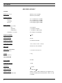
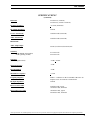
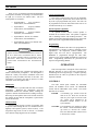
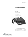
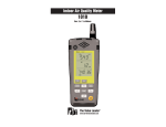
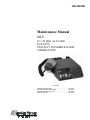
LBI-38435B Maintenance Manual MLS 29.7-42 MHz, 42-50 MHz 60 WATTS TWO-WAY FM MOBILE RADIO COMBINATION INCLUDES TRANSMITTER/RECEIVER ..................................................LBI-38436 SYSTEM CONTROL/SYNTHESIZER....................................LBI-38437 FRONT PANEL/CONTROL UNIT ..........................................LBI-38424 SERVICE SECTION ..............................................................LBI-38438 LBI-38435B NOTICE! The software contained in this device is copyrighted by Com-Net Ericsson Critical Radio Systems, Inc. Unpublished rights are reserved under the copyright laws of the United States. This manual is published by Com-Net Ericsson Critical Radio Systems, Inc., without any warranty. Improvements and changes to this manual necessitated by typographical errors, inaccuracies of current information, or improvements to programs and/or equipment, may be made by Com-Net Ericsson Critical Radio Systems, Inc., at any time and without notice. Such changes will be incorporated into new editions of this manual. No part of this manual may be reproduced or transmitted in any form or by any means, electronic or mechanical, including photocopying and recording, for any purpose, without the express written permission of Com-Net Ericsson Critical Radio Systems, Inc. Copyright 1994-2000, Com-Net Ericsson Critical Radio Systems, Inc. All rights reserved. 2 LBI-38435B TABLE OF CONTENTS SPECIFICATIONS..................................................................................................................................................4 DESCRIPTION........................................................................................................................................................6 OPERATION ...........................................................................................................................................................8 CONTROLS .......................................................................................................................................................8 INDICATORS ....................................................................................................................................................9 USING THE RADIO (2 CHANNEL) ..............................................................................................................11 USING THE OPTIONAL EIGHT (8) OR SIXTEEN (16) CHANNEL RADIO (WITHOUT SCAN) ...........11 SCAN OPERATION ........................................................................................................................................11 TO PROGRAM SCAN CHANNELS AND SELECT PRIORITY ..................................................................12 USING THE OPTIONAL EIGHT (8) OR SIXTEEN (16) CHANNEL RADIO (WITH SCAN) ...................13 MAINTENANCE ...................................................................................................................................................13 DTMF MICROPHONE MODIFICATION......................................................................................................11 INTERCONNECTION DIAGRAM.....................................................................................................................15 ILLUSTRATED MECHANICAL PARTS BREAKDOWN ..............................................................................16 INTERCONNECTION KIT (JHM-156S) ...........................................................................................................17 LIST OF FIGURES Figure Title Page Figure 1 – MLS Mobile Two-Way FM Radio........................................................................................................7 Figure 2 – Two Channel Radio ...............................................................................................................................9 Figure 3 – Eight Channel Radio Without Scan/With Scan ................................................................................10 Figure 4 – Sixteen Channel Radio Without Scan/With Scan .............................................................................10 Figure 5 – DTMF Microphone Modification.......................................................................................................14 CAUTION Although the highest voltage in this mobile equipment is supplied by the vehicle battery, high currents may be drawn under short circuit conditions. These currents can possibly heat objects such as tools, rings, watchbands, etc., enough to cause burns. Be careful when working near energized circuits! High level RF energy in the Transmitter Power Amplifier assembly can cause burns upon contact. Keep away from these circuits when the transmitter is energized! NOTE This equipment has been tested and found to comply with the technical specifications in Part 15, subpart J of the FCC rules for a Class A and Class B computing device. 3 LBI-38435B SPECIFICATIONS* SYSTEM Radio Type FCC# MLSL161 (29.7-42 MHz) MLSL261 (42-50 MHz) Frequency Range: Transmitter Receiver Transmitter Receiver 29.7 to 42 MHz, 42 to 50 MHz 29.7 to 42 MHz, 42 to 50 MHz Two Frequency Spread 1 MHz Two Frequency Spread 1 MHz Battery Drain: Receiver (13.8 VDC) Off Squelched Unsquelched 0.03 Amperes 0.70 Amperes nominal 1.15 Amperes (4 Watt audio) Transmitter (13.6 VDC) 20.0 Amperes (60 Watts RF) Frequency Stability +5 ppm Channel Spacing 20 kHz Frequency Capacity 16 Channels maximum Temperature Range -30°C (-22°F) to +60°C (+140°F) Duty Cycle 80% Receive, 20% Transmit Dimensions (H X W X D) (Less Accessories) 5.5 cm X 18.5 cm X 24 cm Weight (Less Accessories) 2.3 kg TRANSMITTER Power Output Conducted Spurious Modulation 60 Watts -62 dB + 5.0 kHz Audio Sensitivity 85 millivolts +3dB Audio Frequency Characteristics (Per RS-152B) Within +1 dB to –3 dB of 6 dB/octave pre-emphasis from 300 Hz to 2500 Hz per EIA standard and +1 dB to –4.5 dB at 3000Hz 4 LBI-38435B SPECIFICATIONS* (Continued) Distortion Less than 3% (1000 Hz) Less than 5% (300 Hz to 3000 Hz) Deviation Symmetry + 0.5 kHz (maximum) RF Output Impedance 50 ohms Carrier Attack Time 30 milliseconds (maximum) Audio Attack Time 50 milliseconds (maximum) RECEIVER Audio Ampl Output (4-ohm speaker) 4 Watts (less than 5% distortion) EIA Sensitivity 12 dB SINAD (EIA method) 20 dB (Quieting method) 0.35 microvolts 0.40 microvolts Selectivity (EIA two-signal method) -70 dB + 20 kHz Spurious Response -70 dB Intermodulation -70 dB Modulation Acceptance + 7 kHz Frequency Response Within + 2.0 dB and –8 dB of a standard 6 dB/octave deemphasis curve from 300 Hz to 3000 Hz EIA RF Input Impedance 50 ohms Receiver Attack Time 90 milliseconds, typical 150 milliseconds, maximum Receiver Recovery Time 100 milliseconds, typical 250 milliseconds, maximum *These specifications are intended primarily for the use of service personnel. Refer to the appropriate Specification Sheet for the complete specifications. 5 LBI-38435B DESCRIPTION The Com-Net Ericsson MLS series mobile radio is a synthesized, wide-band radio, utilizing microcomputer technology to provide high reliability, high quality, and high performance in two-way, FM, mobile communication. The MLSL161 and MLSL261 radios operate in the 29.7 to 42 MHz and the 42 to 50 MHz frequency ranges respectively and provide an RF power output of 60 watts with an allowable channel separation of 1 MHz transmit and 1 MHz receive. The small size of the MLS makes it ideal for front mounting in conventional vehicles, with all operating controls and indicators located on the Control Panel. The standard radio with Control Panel is equipped with the following: The Transmitter circuit consists of a broadband, fixed-tuned driver module and a power amplifier. The RF power output level is internally adjustable for rated power output. Once the level is set, a sensing control circuit holds the power constant over the temperature and/or voltage variations within specified limits. Receiver • Microcomputer control The dual conversion receive circuit consists of a 29.7–42/42-50 MHz front end section and two mixer/IF sections operating at 20.8 MHz and 455 kHz. The receive circuit also contains a squelch and audio section. The audio section provides a 4-Watt audio output into a 4-ohm load (internal speaker or external speaker). • RF channel synthesizer Frequency Synthesizer • Up to 16 RF channels • LED channel display • Channel Guard (CTCSS or DCG) • Carrier Control Timer (CCT) The synthesizer drives the transmit circuit exciter and the receive circuit first mixer and consists of a synthesizer chip, a prescaler, a reference oscillator, and the voltagecontrolled oscillators (VCOs). The synthesized frequency is controlled by the personality EEPROM and applied to the Transmitter/Receiver board. • + 0.0005% (5 PPM) frequency stability The radio circuitry consists of a System Control Frequency Synthesizer Board (A801), a Transmitter/Receiver Board (A802) and a Front Panel/Control Unit (A803 and A804). The circuitry also consists of Control Indicator Panel (A804), an internal speaker, an antenna jack, a connector for the microphone, and a power supply cable (refer to Figure 1 – Mobile Layout Diagram). No power supply is used since the highest supply voltage required for the operation of the radio is provided by the vehicle battery. The radio is designed for operation in a 12-volt, negative ground, vehicular system or as an AC-powered mobile. Access to each circuit board is easily achieved by loosening four (4) screws in the rear of the top and bottom covers, then removing each cover. All tuning controls are also accessible with the covers removed. Access to the Control and Indicator circuitry can be achieved by removing the four (4) screws securing the front panel to the chassis. 6 Transmitter An Electrically Erasable PROM (EEPROM), on the System Control and Frequency Synthesizer Board (A801) stores the binary data for the transmit and receive frequencies, Channel Guard tones, digital codes, and CCT timing periods. The EEPROM is field programmable and each channel can be individually programmed or reprogrammed for the desired transmit and receive frequencies, CG tones, and digital codes or CCT timing. Control Panel The Control Panel consists of the front panel housing an internal speaker and a plug-in module (A804) which determines the number of channels (2 to 16) and mode of operation (with or without scan). Refer to Maintenance Manual LBI-38424, listed in the Table of Contents of this publication. The panel is made of highly durable plastic with rounded corners and recessed controls, and indicators for passenger safety requirements (refer to the OPERATION section for a description of the Control and Indicator functions). LBI-38435B Figure 1 – MLS Mobile Two-Way FM Radio 7 LBI-38435B There are five (5) different optional interchangeable control panels available for selecting a two channel radio, an eight (8) or sixteen (16) channel radio. The five control panels are as follows: • Optional MK1J: Two (2) Channel without Scan (19A705800P100) • Option MK1L: Eight (8) Channel without Scan (19A705800P101) • Option MK1N: Eight (8) Channel with Scan (19A705800P102) • Option MK1P: Sixteen (16) Channel without Scan (19A705800P103) • Option MK1R: Sixteen (16) Channel with Scan (19A705800P104) CAUTION Optional Control Panels 19A705800P100 thru P104 are for use in MLS radios 19A705800P1 thru P7 ONLY. They are NOT compatible with the 19A704991() series MLS radios. MLS radios 19A704991P1 thru P7 use Control Panels 19A704991P101 thru 19A704991P104 ONLY. Carrier Control Timer The Carrier Control Timer turns off the transmitter after the microphone push-to-talk (PTT) switch has been keyed for a pre-programmed time period. The timer can be programmed to time out and sound an alert tone in 30 second increments up to 7.5 minutes. External Speaker (Optional) An optional 4-Watt, 4-ohm external speaker is available for use with the radio. The speaker is supplied with a mounting bracket and mounting hardware. The speaker leads connect through connector J701 on the back of the radio (refer to applicable Installation Manual). Programming The EEPROM allows the radio to be programmed or reprogrammed, as needed, to adapt to changing system requirements. RF frequencies, Channel Guard tones, digital codes, and CCT can be reprogrammed. The EEPROM is programmed through the radio MIC connector J701, using an IBM compatible PC and special cable. Programming instructions are provided in the respective Programming Manual. OPERATION Microphone The mobile radio uses a dynamic microphone with a built-in transistorized pre-amplifier. The microphone is housed in a sturdy case and the extendable coiled cord plugs into a jack provided at the back of the radio. The microphone is secured to the radio by means of a strain relief hook on the microphone cable. Hookswitch A hookswitch is provided with the radio to hold the microphone. Removing the microphone from the hookswitch disables the Channel Guard, enabling the operator to monitor the channel before sending a message. Removing the microphone while in the SCAN mode will also disable SCAN until the microphone is placed back into the hookswitch. Channel Guard Channel Guard provides a means of restricting calls to specific radios through the use of a continuous tone or digitally coded squelch system (CTCSS or DCG). Tone frequencies range from 67.0 Hz to 210 Hz. 33 standard tones and 104 unique digital codes are available. . 8 This section provides a description of the Control and Indicator functions as well as the basic procedures for transmitting and receiving messages. Complete operating instructions for the radio are provided in the respective Operator’s Manual. CONTROLS The radio control panel contains the VOLUME control, the POWER on/off switch, the MONITOR switch, and the CHANNEL select switch. The switch functions are as follows: POWER A momentary type switch to turn the radio on or off. Press once to turn the radio on; press again to turn the radio off. Power ON is indicated by an illuminated channel number on the system module. VOLUME Two momentary type switches to adjust the volume. Press and hold the MAX (up arrow) to increase the volume. Press and hold the MIN (down arrow) to decrease the volume. LBI-38435B MONITOR CHANNEL A momentary type switch to allow you to monitor the selected channel before transmitting a message. It disables Channel Guard and squelch and will allow you to hear noise if the channel is not busy. This may be convenient when setting the volume to the desired listening level. Two momentary type switches. Press CHAN 1 (up arrow) to select channel 1; press CHAN 2 (down arrow) to select channel 2. The selected channel number will be illuminated on the control module. With an eight or sixteen channel radio, two momentary type switches select channels electronically. Press and hold the ADD switch to increase the channel number; press and hold the DELETE switch to decrease the channel number. The selected channel is displayed by a 7-segment display. ADD DELETE SCAN When used in conjunction with the SCAN switch, adds channels to the scan list. conjunction with the CHANNEL switch, it enables the ADD/DELETE function to allow the scan list to be modified. When turned on, the scan indicator is illuminated. INDICATORS XMIT (Transmit) Lights when your message is being transmitted. BUSY Lights when the channel is in use. CHANNEL Lights to indicate which channel has been selected. 1 2 P1 When lit, indicates that the channel displayed is a Priority 1 scan channel. P2 When lit, indicates that the channel displayed is a Priority 2 scan channel. S When lit, indicates that the channel displayed is a non-priority scan channel. SCAN When lit, indicates that the radio is operating in the scan mode. When used in conjunction with the SCAN switch, deletes channels from the scan list. The channel indicator displays the following conditions: A momentary type switch to turn the scan function on or off. When used in Figure 2 – Two Channel Radio 9 LBI-38435B • When scan is off, the selected channel is shown. • When scan is on, the last pre-scan selected • channel is shown when no signal is being received. When a scan channel is being received and audio is present in the speaker, the received channel is shown. Figure 3 – Eight Channel Radio Without Scan/With Scan Figure 4 – Sixteen Channel Radio Without Scan/With Scan 10 LBI-38435B USING THE RADIO (2 CHANNEL) 2. Select the desired channel by pressing either the ADD or DELETE switch. To Receive a Message: 3. Press and hold MONITOR switch and then adjust the VOLUME controls for the desired listening level. Release MONITOR switch. 4. Radio is now ready to receive a message. 1. Turn the radio on (channel indicator lit). If not, press POWER switch. 2. Select the desired channel by pressing either the 1 or 2 switch. 3. Press and hold MONITOR switch and then adjust VOLUME controls for the desired listening level. Release MONITOR switch. 4. Radio is now ready to receive a message. To Transmit a Message: 1. Confirm that the radio is turned on (channel indicator lit). If not, press POWER switch. 2. Select the desired channel by pressing either the 1 or 2 switch. 3. Press and hold MONITOR switch and then adjust VOLUME controls for the desired listening level. Release MONITOR switch. 4. 5. 6. 7. Decide what you want to say. If you intend a lengthy message (or several messages) the vehicle engine should be running to maintain the battery charge. Observe the BUSY indicator and press the MONITOR switch to assure that the channel is not in use. Remove microphone from hookswitch, press the PTT switch and identify yourself. The XMIT indicator will light each time the PTT switch is pressed. Release the PTT switch and wait for an answer to your call. Then, complete your message. NOTE Always speak in a normal voice. Hold the microphone cupped in your hand and touching your cheek lightly. Speak across the face of your microphone, not directly into it. Shouting will actually reduce your radio range, so do not speak any louder than normal. USING THE OPTIONAL EIGHT (8) OR SIXTEEN (16) CHANNEL RADIO (WITHOUT SCAN) To Receive a Message: 1. Turn the radio on (channel indicator lit). If not, press POWER switch. To Transmit a Message: 1. Confirm that the radio is turned on (channel indicator lit). If not, press POWER switch. 2. Select the desired channel by depressing either the ADD or DELETE switch. 3. Press and hold MONITOR switch and then adjust the VOLUME controls for the desired listening level. Release MONITOR switch. 4. Decide what you want to say. If you intend a lengthy message (or several messages) the vehicle engine should be running to maintain the battery charge. 5. Observe the BUSY indicator and press the MONITOR switch to assure that the channel is not in use. 6. Remove the microphone from the hookswitch, press the PTT switch and identify yourself. The XMIT indicator will light each time the PTT switch is pressed. 7. Release the PTT switch and wait for an answer to your call. Then, complete your message. SCAN OPERATION The SCAN function allows monitoring of up to eight or sixteen receive channels (depending upon which control module is being used). The scanned channels may be any frequency within the frequency band limits of the radio and may be Channel Guard protected. The radio message will then be received only if the correct Channel Guard signal is present. Any channel may be scanned with or without priority level. One channel may be programmed for Priority 1 (P1) and another for Priority 2 (P2) with any or all remaining programmed channels being scanned as nonpriority (S). Receive Scan Rate The scan rate for the radio will vary depending upon the number of channels programmed into the scan memory and whether or not Channel Guard is programmed. For a sixteen channel radio, the scan rate will vary from 1.1 to 4.4 seconds for non-priority channels, and 0.3 to 1.2 seconds for Priority 1 and 2 11 LBI-38435B channels. The scan rate will be faster when fewer channels are programmed into scan memory. • Radio is in scan mode but there is no carrier activity to top the scan on any channel. Removing the microphone from its hookswitch will stop the scanning activity and the radio will revert to the pre-scan selected channel. Replacing the microphone will enable the scan mode after a few seconds delay. • Radio is in scan mode and carrier activity on a channel has caused scan to stop. Removing the microphone from its hookswitch will keep that channel selected. When push-to-talk (PTT) is pressed on the microphone, the transmit channel will be the displayed channel. The channel can be changed during this time as needed, but will be forgotten when scanning resumes. Placing the microphone back on the hookswitch will cause scan to resume, after a few seconds delay. • The Channel Guard decode is disabled whenever the microphone is removed from its hookswitch. • During the scan mode, the MONITOR and CHANNEL selection functions are disabled if scan is not stopped on a channel. Scan operation will be determined by the following conditions: • Priority 1, Priority Programmed* 2, and Non-Priority The Priority 1, Priority 2, and up to six (6) remaining channels in an eight (8) channel radio or fourteen (14) channels in a sixteen (16) channel radio will be scanned. Once a carrier is detected (or correct Channel Guard tone is decoded), the digital display will indicate the channel. Sampling of the Priority 1 and Priority 2 channels continues while receiving a message on a non-priority channel. Should a Priority 1 or Priority 2 channel carrier (and correct Channel Guard) be detected while a non-priority channel is being received, the applicable indicator (P1 or P2) lights and the channel is switched to the Priority 1 or 2 channel, regardless of what is being received on the non-priority channel. If a Priority 2 channel is detected, sampling of the Priority 1 channel continues. Once a carrier (and correct Channel Guard) is detected on the Priority 1 channel, the channel is switched to the Priority 1 channel regardless of what is being received on another channel (Non-priority or Priority 2). No sampling occurs during transmit or if a Priority 1 channel is receiving. • Non-Priority Programmed: Up to eight/sixteen (8/16) non-priority channels may be scanned. Once a carrier is detected (or correct Channel Guard tone is decoded), the digital display will indicate the channel. Scan will stop and remain on the channel until the carrier disappears, after a few seconds scanning resumes. The channels will be scanned in descending order. TO PROGRAM SCAN CHANNELS AND SELECT PRIORITY The selection of scan channels and priority is frontpanel programmable using the SCAN switch in conjunction with the ADD and DELETE switch. Non-Priority 1. Confirm that radio is turned on (channel number is lit). If not, press the POWER switch. 2. If SCAN indicator is lit, press and release the SCAN switch to disable scan function. 3. Select desired channel using the ADD or DELETE switch. 4. Press and hold SCAN switch, then press the ADD switch once to add the channel to the scan list. The “S” indicator light will light to indicate that the channel is now in the scan program. 5. Release SCAN switch. 6. Repeat steps 2 through 5 for each channel (up to 8/16) to be added to the scan list. NOTE *The rate the P1 and P2 channels are sampled while listening to a non-priority channel depends upon whether an RF carrier is present or not. If no carrier is present on P1 or P2, the scan rate is fast. If a carrier is detected but incorrect Channel Guard is present, the rate slows considerably. This prevents the non-priority signal from being badly distorted by the larger mute times needed to detect Channel Guard. If Channel Guard is not programmed for P1 or P2, the scan sampling rate remains fast. Transmit In Scan Mode Several characteristics in the transmit mode occur if the radio has been placed in the scan mode of operation. 12 Priority 2 (P2)** 1. Perform steps 1 through 3 of the Non-Priority procedure. LBI-38435B 2. Press and hold SCAN switch then press the ADD switch twice. The selected channel will now become the Priority 2 channel and the “P2” indicator will light to indicate that the channel is now in the scan program as Priority 2. 3. Release SCAN switch. USING THE OPTIONAL EIGHT (8) OR SIXTEEN (16) CHANNEL RADIO (WITH SCAN) Perform the procedure listed in the paragraph “Using the Optional Eight (8) or Sixteen (16) Channel Radio (Without Scan).” Priority 1 (P1)** 1. 2. 3. Perform steps 1 through 3 of the Non-Priority procedure. Press and hold SCAN switch; then press the ADD switch three times. The selected channel will now become the Priority 1 channel and the “P1” indicator lights to indicate that the channel is now in the scan program as Priority 1. Release SCAN switch. Scan Mode Press and release SCAN switch to enable the scan function. The scan indicator should light and the following conditions apply: • Only programmed scan channels will received. • As long as no signal is being received, the digital display will indicate the pre-scan selected channel. If S, P1, or P2 indicator is not lit, no signal will be received on this channel since it has not been programmed for scan. • When a signal is received, the display indicates the channel received and the priority level. • Removing microphone from hookswitch locks the radio onto the received scan channel. Pressing the PTT switch on the microphone allows transmission on the received scan channel. • Scan resumes, after few seconds delay, when the microphone is returned to the hookswitch. Prescan channel will again be displayed and will be the transmit channel if user removes microphone from hookswitch before another channel is detected. • Channel changes and other normal operations are allowed while off-hook, but will be immediately forgotten when the microphone is placed onhook. NOTE **If a Priority 1 or 2 scan channel already exists when programming a new Priority 1 or 2 scan channel, the old Priority 1 or 2 channel becomes a Non-Priority scan channel. Delete Scan Channels (S, P1, P2) 1. Confirm that radio is turned on (digital display lit). If not, press POWER switch. 2. If SCAN indicator is lit, press and release SCAN switch to disable scan function. 3. Select the desired channel to be removed from the scan list using the ADD or DELETE switch. 4. Press and hold SCAN switch; then press the DELETE switch once. This removes the selected channel from the scan list. All scan indicators (S, P1, P2, and SCAN) will be off. 5. Release SCAN switch. 6. Repeat preceding steps 2 through 5 for each channel to be removed from the scan list. Review 1. Confirm that radio is turned on (channel indicator is lit). If not, press POWER switch. 2. If SCAN indicator is lit, press and release SCAN switch to disable scan function. 3. Select each channel (one at a time) using the ADD or DELETE switch and confirm channels included on the scan list. The scan indicator (S, P1, P2) will light for each channel programmed. be MAINTENANCE Maintenance Information for the Lowband MLS mobile radio is provided in Service Section Manual LBI38438, listed in the Table of Contents of this publication. The Service Section Manual includes information as follows: • Disassembly Procedures • Transmit Alignment Procedures • Receiver Alignment Procedures • Receiver Test Procedures • Troubleshooting Procedures • Test Point Voltage Readings 13 LBI-38435B • Receiver Voltage Readings • IC and Chip Component Replacement Procedures 6. Also provided in the Maintenance Manuals for each circuit board are IC DATA SHEETS with information about each IC package used on that particular circuit board. DTMF MICROPHONE MODIFICATION 1. Remove the top radio cover and locate the System Control/Synthesizer board (A801). 2. To isolate J701-1 from the printed board, carefully cut the zigzag run on the component side of the board near capacitors C613 and C615 (see Figure 5). 3. Solder a wire (#24 AWG) to J701-1 on the component side of the board. 4. Solder the other end of this wire to the output of the 9-Volt Regulator IC207, pin 3. Pin 3 of IC207 is the pin nearest the rear wall of the radio. 5. Locate the connector plug on the DTMF microphone and insert the blue wire in P701-1. If an external speaker is desired with the DTMF microphone, perform the following modifications: a) On the Transmitter/Receiver board (A802), connect jumper plug P502/P551 across pins 1 and 2 of J502/J551 (IN). b) Verify that the internal speaker plug P503/P552 is connected to speaker jack J503/J552. c) Locate the internal speaker in the front cap assembly and cut the two wires from the speaker terminals. d) Solder two extension wires to these cut wires and run the wires along the side wall near the System Control/Synthesizer board (A801) and through the opening around J701 at the rear of the radio. e) Add a connector to these wires and a mating connector to the leads of the external speaker. f) Strain relieve the wires inside the radio with a tie wrap at J701-8. Figure 5 – DTMF Microphone Modification 14 INTERCONNECTION DIAGRAM LBI-38435B 15 LBI-38435B 16 ILLUSTRATED MECHANICAL PARTS BREAKDOWN MECHANICAL PARTS LIST LBI-38435B 17 INTERCONNECTION KIT 18 LBI-38435B LBI-38435B This Page Intentionally Left Blank 19 Com-Net Ericsson Critical Radio Systems, Inc. P.O. Box 2000 Lynchburg, Virginia 24501 1-800-528-7711 (Outside U.S.A. 804-592-7711) Printed in U.S.A. ADDENDUM NO. 1 TO LBI-38435B (PCML) This addendum covers connection changes when using External Speaker Option LS1D with MLS Mobile Radios. It also covers a part number change for the radio Front Cabinet. EXTERNAL SPEAKER OPTION LS1D The MLS radio is normally configured for internal speaker operation. When an external speaker is used, J551 jumper connections on the Transmitter/Receiver board must be changed. SPEAKER J551 CONNECTION Internal J551-1 to J551-2 External J551-2 to J551-3 MECHANICAL PARTS LIST Change from: 42 Change to: 42 B19/MTV003860 Cabinet, front B19/MPBC09868 Cabinet, front