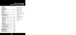
1
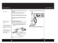
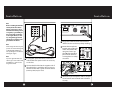
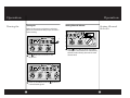
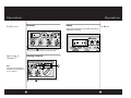
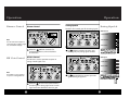
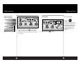
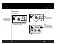
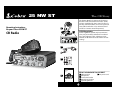
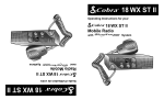
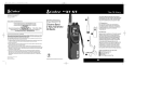
How to Use Your
Cobra 25 NW ST
Contents
Features...........................................................................................1
The CB Story
Controls & Indicators ................................................................A2
Our Thanks to You ......................................................................A3
Installation
Location.......................................................................................2
Mounting and Connection...................................................2
Antennas
CB Antenna ................................................................................6
Marine Installation...................................................................6
Ignition Noise Interference ...................................................7
Operating Your 25 NW ST
Turning On Your CB .................................................................8
Setting Channel Selector.......................................................9
To Receive ...................................................................................10
Selecting a Channel ................................................................10
S-Meter.........................................................................................11
SoundTracker™ System .........................................................12
Activating SoundTracker™ ..................................................13
Dimmer Control........................................................................14
RF Gain Control.........................................................................14
Setting Squelch.........................................................................15
To Transmit .................................................................................17
Setting Dynamike ....................................................................18
Transmit .......................................................................................19
RF Meter ......................................................................................19
External Speaker.......................................................................20
PA (Public Address)..................................................................21
ANL (Automatic Noise Limiter) Switch.............................23
NB, OFF (Noise Blanker) Switch...........................................23
Temporary Mobile Set-Up.....................................................24
Home And Office Set-Up.......................................................25
How Your CB Can Serve You...................................................27
A Few Rules You Should Know............................................27
Channel 9 Emergency Messages .......................................27
CB 10 Codes ...............................................................................29
Frequency Ranges......................................................................31
25 NW ST Specifications..........................................................32
Warranty Information ..............................................................33
Optional Accessories.................................................................34
Features of This Product
• 40 CB Radio Channels
• SoundTracker ™ System
• Heavy-Duty Dynamic
Microphone
• Full 4 Watts AM RF Power Output
• Instant Channel 19 and 9
• Front Panel 4-Pin Microphone
Connector
• Switchable Noise Blanker
• Switchable Automatic
Noise Limiter
• Adjustable Dynamike Boost
• Tactile Controls
• Illuminated Front Panel
• Dimmer Control
• RF Gain
• 9 ft. mic cord
CAUTION
RISK OF ELECTRIC SHOCK
DO NOT OPEN
!
CAUTION: TO REDUCE THE RISK OF ELECTRIC
SHOCK DO NOT REMOVE COVER (OR BACK)
NO USER SERVICEABLE PARTS INSIDE
REFER SERVICING TO QUALIFIED SERVICE
PERSONNEL
1
!
Installation
Installation
Location
Location
Plan location of transceiver and microphone
bracket before starting the installation.
DATE OF
MFG :JUNE 98
Select a location that is convenient for operation,
yet does not interfere with the driver or passenger.
FCC ID:BBO3K229LTD
COBRA
MADE IN CHINA
ANT
PA.SP. EXT.SP.
+ POWER –
SERIAL NO.:806135776
PRECISION ENGINEERED PRODUCT OF
COBRA ELECTRONICS CORP. CHICAGO, ILL.60707
The transceiver is usually mounted to the underside of the dash with the microphone bracket
beside it.
Mounting and
Connection
Mounting and Connection
1
Note
The transceiver is held in the
universal mounting bracket by
two thumbscrews which allow
for adjustment at a convenient
angle.
Hold the radio with the mounting bracket in
the exact desired location. If there is no interference, remove the bracket and use it as a
template to mark the location for the mounting screws.
3
Connect the antenna cable plug to the receptacle marked “ANT” on the back of the unit.
The bracket includes two selftapping screws and star washers. The mounting must be
mechanically strong, conveniently located.
2
Drill the holes and secure the bracket.
continued
2
3
Installation
Installation
Note
Before installing the CB radio,
visually check the vehicle’s
battery connection to determine which terminal, positive
or negative, is grounded (positive is the larger of the two)
to the engine block (or chassis). A negatively grounded
vehicle has its negative lead
grounded to the chassis.
OF
JUNE 98
FCC ID:BBO3K229LTD
COBRA
ANT
PA.SP. EXT.SP.
+ POWER –
MADE IN CHINA
06135776
NGINEERED PRODUCT OF
TRONICS CORP. CHICAGO, ILL.60707
6
Plug power cable into back of unit marked
“Power”. Be sure to observe polarity markings.
7
Mount the microphone
bracket on the right side
of the unit (driver’s left)
using two screws supplied. Bracket should be
placed under the dash
so microphone is readily
accessible.
Note
Connecting to an accessory fuse
prevents the unit from being left
on accidentally, and also permits operating the unit without
running the engine.
Note
4
In positive ground vehicles the
red wire goes to the chassis and
the black wire is connected to
the ignition switch.
In a negative grounded vehicle, connect the
red lead of the DC power cord to an accessory
12 volt fuse.
25 N
RF
SIG 1
5
Connect the black lead to the negative side of
the vehicle. This is usually the chassis. Any convenient location with a good electrical contact
(remove paint) may be used.
5 79
+30dB
OFF
8
4
3
MIN
Attach the 4-pin microphone cable to receptacle on front of unit and Install unit in bracket
securely.
5
Antennas
Ignition Noise Interference
CB Antenna
CB Antenna
Since the maximum allowable power output of
Note
the transmitter is limited by the IC/FCC, the
For optimum performance in
antenna is critical in affecting transmission dispassenger cars the ideal antentance. Only a properly matched antenna system
na location is on the center of
will allow maximum power output. Cobra loaded
the roof. Second choice is on the
type antenna models are highly recommended
center of the trunk.
for most installations. Consult your Cobra dealer
for further details.
Note
Because many newer trucks
feature fiberglass door skins, the
outside mirror must be grounded to the chassis via a ground
strap, if the antenna is mounted
on the mirror bracket.
DATE OF
MFG :JUNE 98
FCC ID:BBO3K229LTD
COBRA
MADE IN CHINA
ANT
PA.SP. EXT.SP.
+ POWER –
SERIAL NO.:806135776
PRECISION ENGINEERED PRODUCT OF
COBRA ELECTRONICS CORP. CHICAGO, ILL.60707
Note
3-way Combination Antennas
are also available which allow
operation of all three bands
(AM-FM & CB), using a single
antenna. However, this type of
antenna usually results in less
than normal transmit and
receive range when compared
to a standard-type “Single
Band” CB antenna.
1
A standard antenna connector is provided
on the transceiver for easy connection.
Use of a mobile receiver at low signal levels is
normally limited by the presence of electrical
noise. The primary source of noise in automobiles
is from the alternator and ignition system.
Typically, when signal level is adequate, the background noise does not present a serious problem.
Also, when extremely low level signals are being
received, the transceiver may be operated with
the vehicle’s engine turned off. The unit requires
very little current and therefore will not significantly discharge the vehicle’s battery.
Even though the Cobra 25 NW ST has an automatic noise limiter, in some installations ignition
interference may be high enough to make good
communications impossible. Many possibilities
exist and variations between vehicles require
different solutions. Consult your COBRA dealer or
a 2-way radio technician for help in locating the
source of a severe noise.
Marine Installation
The transceiver will not operate at maximum efficiency in a boat without a ground plate, (unless it
has a steel hull). Before attempting installation ,
consult your dealer for information regarding an
adequate grounding system and prevention of
electrolysis between fittings in the hull and water.
6
7
Operation
Operation
Turning On
Turning On
Setting Channel Selector
Make sure the power cord, antenna and microphone are connected to their proper connectors
before starting.
Setting Channel
Selector
25 NW ST
25 NW ST
MIN
1
1
The CB/PA button should be in the
CB position.
MAX
MIN
MAX
Select
one of forty channels and adjust
volume. The selected channel is indicated by
the LED readout directly above the channel
selector knob
25 NW ST
2
8
Rotate the On/Off Volume knob
a normal listening level.
clockwise to
9
Operation
To Receive
Operation
S-Meter
To Receive
S-Meter
Swings proportionately to strength of incoming
signal when receiving.
25 NW ST
25 N
1
Selecting A
Channel
Rotate the
On/Off Volume knob clockwise
the green RT/TX LED will be illiuminated.
Selecting A Channel
25 NW ST
Note
Switch to 9 (Emergency) or 19
(Information) for instant access
to these channels.
1
10
Switch to
NOR to select desired channel.
11
Operation
Operation
The SoundTracker TM System
Note
SoundTracker™ gives you
clearer, cleaner reception to
improve CB communications
while on the air.
While previous systems only “blanket out” or limit
noise in higher sound frequencies, the revolutionary new SoundTrackerTM System actually reduces
noise while leaving the signal intact in the reception mode. In the transmission mode, it actually
strengthens the signal, providing you with a
significant reduction in noise on reception
and transmission.
Sound clarity is measured by the ratio
of the signal level to the noise level.
The higher the signal-to-noise ratio,
the better the sound.
How SoundTracker TM Works
Activating
SoundTracker™
Activating SoundTracker™
NW ST
PUSH &
RELEASE
MAX
1
MIN
MAX
Push and release the
ST button. Red LED
is illuminated when SoundTracker™ is
turned on.
On Reception - “Cuts noise coming in”
With a normal CB, distant signals fall below
the squelch level and are unintelligible. With a
SoundTrackerTM CB, the noise level is cut up to
90%, which increases the signal-to-noise ratio
and dramatically improves signal clarity. This also
allows you to significantly reduce the squelch
level, which greatly expands your listening range.
On Transmission - “Strengthens signals going out”
A SoundTrackerTM CB strengthens the transmit
signal by more effectively using the available RF
power output of the CB. The result is improved
transmission signal clarity and an expanded
transmission range.
12
13
Operation
Operation
Setting Squelch
Dimmer Control
Dimmer Control
Setting Squelch
Squelch is the “control gate” for incoming signals.
Gate closed
25 NW ST
25 NW ST
STRONG SIGNALS
RF
SIG 1
3
5 79
+30dB
MEDIUM SIGNALS
The Dim controls the brightness
of the front panel, signal strength
meter and channel display.
MIN
1
MAX
MIN
MAX
OFF
Rotate the
DIM knob clockwise for
maximum brightness; counter-clockwise
for minimum.
1
MIN
MIN
MAX
Full
clockwise rotation closes the gate
allowing only very strong signals to enter.
RF Gain Control
RF Gain Control
MAX
NOISE
Gate open
25 NW ST
The RF Gain is used to optimize reception in
strong or weak signal areas.
WEAK SIGNALS
G AT E C L O S E D
SQL
Note
RF
SIG 1
3
5 79
+30dB
STRONG SIGNALS
MEDIUM SIGNALS
25 NW ST
RF
SIG 1
3
5 79
+30dB
OFF
MIN
MAX
MIN
MAX
WEAK SIGNALS
Note
The RF Gain is used to optimize
reception in weak signal areas.
2
1
14
MIN
MAX
MIN
NOISE
MAX
G AT E
OPEN
OFF
Full
counterclockwise rotation opens the
“gate” allowing all signals in.
Rotate the
RF Gain knob counterclockwise
to reduce gain in strong signal areas. In weak
signal areas turn clockwise to increase gain.
15
Operation
Operation
Gate set to Desired
Squelch Setting (DSS)
To Transmit
To Transmit
25 NW ST
RF
SIG 1
STRONG SIGNALS
3
5 79
+30dB
25 NW ST
Caution!
Be sure the antenna is properly
connected to the radio before
transmitting. Prolonged transmitting without an antenna, or
a poorly matched antenna,
could cause damage to the
transmitter.
MEDIUM SIGNALS
OFF
MIN
MAX
MIN
MAX
NOISE
G AT E
WEAK SIGNALS
3
16
To achieve the Desired Squelch Setting (DSS),
turn the Squelch control
counterclockwise
until you hear noise. Now turn the control
clockwise just until the noise stops. This is the
DSS setting.
MIN
1
MAX
Select desired
MIN
MAX
channel.
17
Operation
Setting
Dynamike
Operation
Setting Dynamike
Transmit
Transmit
This controls the microphone sensitivity
(outgoing audio level).
PUSH &
HOLD
25 NW ST
RF
SIG 1
3
5 79
+30dB
OFF
1
MIN
MAX
MIN
Initially, set fully
clockwise so that maximum voice volume is available. Dynamike
may have to be reduced in some conditions.
MAX
1
Push and hold mic button to transmit.
Transmitter is now activated. When transmitting, hold the microphone two inches from
your mouth and speak in a clear, normal voice.
Release to receive.
RF Meter
RF Meter
This meter swings proportionately to the RF
output (outgoing signal) while transmitting.
18
19
Operation
Operation
External Speaker External Speaker
PA (Public Address)
PA (Public
Address)
The external Speaker jack is used for remote
receiver monitoring.
Note
ANT
FCC ID:BBO3K229LTD
The external speaker should
have 8-ohm impedance and be
rated to handle at least 4.0
watts. When the external speaker is plugged in, the internal
speaker is automatically disconnected.
COBRA
PA.SP. EXT.SP.
+ POWER –
MADE IN CHINA
FCC ID:BBO3K229LTD
COBRA
MADE IN CHINA
ANT
PA.SP. EXT.SP.
+ POWER –
RODUCT OF
P. CHICAGO, ILL.60707
Note
Speaker should have 8-ohm
impedance and be rated to
handle at least 4.0 watts.
ODUCT OF
P. CHICAGO, ILL.60707
Note
Note
1
1
Cobra external speakers are
rated at 15 watts.
Connect an external PA speaker to the PA jack
on the rear panel.
Connect an external speaker to the external
speaker jack on the rear panel.
Note
25 NW ST
Activity on the CB channel
will be heard through the PA
speaker. Adjust Volume Control
for normal listening level.
RF
SIG 1
3
5 79
+30dB
OFF
2
20
The speaker should be directed
away from the microphone to
prevent acoustic feedback.
Set
MIN
MAX
M
CB PA switch to PA position.
21
Operation
Operation
ANL (Automatic
Noise Limiter)
Switch
ANL (Automatic Noise Limiter) Switch
PUSH &
HOLD
25 NW ST
RF
SIG 1
3
5 79
+30dB
OFF
1
3
Push and hold microphone button and speak
in a normal voice. Your voice will sound on the
PA speaker.
MIN
25 NW ST
RF
3
5 79
+30dB
SIG 1
3
5 79
OFF
MIN
MAX
Adjust PA speaker volume with the
Dynamike control.
MIN
MAX
Note
+30dB
VOL
22
NB, OFF
(Noise Blanker)
Switch
NB, OFF (Noise Blanker) Switch
RF
4
M
When switched to ANL the Automatic Noise
Limiter is activated. This helps reduce noise
created by the vehicle’s electronics.
25 NW ST
SIG 1
MAX
OFF
The RF noise blanker is very
effective in reducing repetitive
noises such as ignition interference.
SQL
MIN
MAX
When switched to NB position the RF Noise
Blanker is activated, providing increased noise
filtration.
When switched to OFF position Noise
Blanking Filtration will be turned off.
23
Temporary Mobile Set-Up
Temporary
Mobile Set-Up
Temporary Mobile Operation
For temporary mobile operation you may want to
purchase an optional cigarette lighter adapter
from your COBRA dealer. This adapter and a magnetic mount antenna allow you to quickly “install”
your transceiver for temporary use.
DATE OF
MFG :JUNE 98
FCC ID:BBO3K229LTD
COBRA
MADE IN CHINA
ANT
Home And Office Set-Up
Base Station Operation
(From 120V AC House Current)
To operate your transceiver from home or office
you will need a 13.8 volt DC Power Pack rated at a
minimum of 2 amps, and a properly installed base
station antenna.
+
PA.SP. EXT.SP.
+ POWER –
SERIAL NO.:806135776
PRECISION ENGINEERED PRODUCT OF
COBRA ELECTRONICS CORP. CHICAGO, ILL.60707
1
24
—
Base Station
Operation
(From 120V AC
House Current)
Warning!
Do not attempt to operate this
transceiver by connecting it
directly to 120 vac.
Simply connect the red (+) and black (-)
leads of the transceiver to the corresponding
terminals of the power pack.
25
Home And Office Set-Up
FCC ID:BBO3K229LTD
COBRA
MADE IN CHINA
ANT
How Your CB Can Serve You
PA.SP. EXT.SP.
+ POWER –
ODUCT OF
P. CHICAGO, ILL.60707
2
3
Plug power cable into back of unit marked
“Power”. Be sure to observe polarity markings.
Connect properly installed and matched base
station antenna.
•
•
•
•
•
•
•
•
•
Warn of traffic problems
Provide weather and road data
Provide help in event of an emergency
Provide direct contact with home or office
Assist police by reporting erratic drivers
Get “local information” to find destination
Communicate with family and friends
Suggest spots to eat and sleep
Keep you alert while traveling
A Few Rules You Should Know
A. Conversations cannot last more than 5 minutes
with another station. A one minute break is
required to let others use the channel.
B. You cannot blast others off the air by use of
illegally amplified transmitters or illegally
high antennas.
C. You cannot use CB to promote illegal activities.
D. Profanity is not allowed.
E. You may not transmit music with a CB.
F. Selling of merchandise and/or services is
prohibited.
1. Set to channel 9 for emergencies
Channel 9
Emergency
Messages
Be sure antenna is properly connected.
2. CB Distress Data
When transmitting an emergency, you should
request a “REACT BASE” and provide the CB
distress data (called CLIP):
C
L
I
P
all Sign
ocation
njuries
roblem
Identify yourself.
Be exact.
Number. Type. Trapped?
Give details and help needed.
Note
If no response on channel 9,
try channels 19 or 14.
Transmit CLIP repeatedly so any monitor can assist.
26
A Few Rules
You Should
Know
27
How Your CB Can Serve You
The IC/FCC gives these examples of permitted
and prohibited messages for channel 9. These are
only guidelines and not all-inclusive:
Permitted
Example Message
Yes
“Tornado sighted six miles north
of town.”
“Post number 10.
No tornado sighted.”
No
Yes
No
Yes
No
Yes
No
Yes
No
28
“Out of gas on Rte 15 at mile
marker 211.”
“Out of gas in my driveway.”
“Four car accident on 401 at
Exit 11. Send police and
ambulance.”
“Traffic moving smoothly on 401.”
“Weather Bureau has issued
thunderstorm warning.
Bring sailboat into port.”
“Attention motorists.
Weather Bureau advises snow
tomorrow will accumulate
4 to 6 cm.”
“Fire in building at 539 Main,
Winnipeg.”
“Halloween patrol number 3.
All quiet.”
How Your CB Can Serve You
CB 10-Codes
CB 10-Codes
Citizen Bands have adopted the “10-CODES” for
standard questions and answers. These codes
provide quick and easy communication, especially
in noisy areas. Following are some of the more
common codes and meanings:
Code
10-1
10-2
10-3
10-4
10-5
10-6
10-7
10-8
10-9
10-10
10-11
10-12
10-13
10-16
10-17
10-18
10-19
10-20
10-21
10-22
10-23
10-24
10-25
10-26
10-27
10-28
Meaning
Receiving poorly
Receiving well
Stop transmitting
OK, message received
Relay message
Busy, stand by
Out of service, leaving
In service, subject to call
Repeat message
Transmission completed standing by
Talking too rapidly
Visitors present
Advise weather/roads
Make pick up at
Urgent business
Anything for us?
Return to base
My location is
Call by phone
Report in person to
Stand by
Completed last assignment
Can you contact
Disregard last info
Moving to channel
Identify your station
29
How Your CB Can Serve You
Code
10-29
10-30
10-33
10-34
10-35
10-36
10-37
10-38
10-39
10-41
10-42
10-43
10-44
10-45
10-50
10-60
10-62
10-63
10-64
10-65
10-67
10-70
10-71
10-77
10-81
10-82
10-85
10-91
10-93
10-94
10-99
10-200
30
Meaning
Time is up for contact
Does not conform to IC/FCC rules
Emergency traffic
Trouble at this station
Confidential information
Correct time is
Wrecker needed at
Ambulance needed
Message delivered
Turn to channel
Traffic accident at
Traffic tie up at
Have a message for
All units within range please report
Break channel
What is next message number?
Unable to copy. Use phone
Net directed to
Net clear
Awaiting your next message/assignment
All units comply
Fire at
Proceed, transmission in sequence
Negative contact
Reserve hotel room for
Reserve room for
My address is
Talk closer to mic
Check my frequency on this channel
Give me a long count
Mission completed, all units secure
Police needed at
Frequency Ranges
The COBRA 25 NW ST transceiver represents one
of the most advanced AM two-way radios used as
a Class D station in the Citizens Radio Service. This
unit features advanced Phase Lock Loop (PLL)
circuitry providing complete coverage of all 40 CB
channels.
Channel
Channel
CB
Freq.
CB
Freq.
Channel In MHz Channel In MHz
1
2
3
4
5
26.965
26.975
26.985
27.005
27.015
21
22
23
24
25
27.215
27.225
27.255
27.235
27.245
6
7
8
9
10
27.025
27.035
27.055
27.065
27.075
26
27
28
29
30
27.265
27.275
27.285
27.295
27.305
11
12
13
14
15
27.085
27.105
27.115
27.125
27.135
31
32
33
34
35
27.315
27.325
27.335
27.345
27.355
16
17
18
19
20
27.155
27.165
27.175
27.185
27.205
36
37
38
39
40
27.365
27.375
27.385
27.395
27.405
31
25 NW ST Specifications
GENERAL
CHANNELS . . . . . . . . . . . . . . . . . . . . . . . CB - 40 CH
FREQUENCY RANGE . . . . . . . . . . . . . . . CB - 26.965 TO 27.405 MHZ
FREQUENCY TOLERANCE . . . . . . . . . . 0.005 %
FREQUENCY CONTROL . . . . . . . . . . . . PLL (PHASE LOCK LOOP) SYNTHESIZER
OPERATING TEMPERATURE
RANGE . . . . . . . . . . . . . . . . . . . . . . . . . . . -30° C TO + 50° C
MICROPHONE . . . . . . . . . . . . . . . . . . . . PLUG-IN DYNAMIC
INPUT VOLTAGE . . . . . . . . . . . . . . . . . . 13.8VDC nom. (positive or negative ground)
CURRENT DRAIN
TRANSMIT: AM FULL MOD., 1.5A (MAXIMUM)
RECEIVE: SQUELCHED, 0.3A;
FULL AUDIO OUTPUT, 1.2A (NOMINAL)
SIZE . . . . . . . . . . . . . . . . . . . . . . . . . . . . .8-5/8” D X 6-3/8”W X 2-13/64” H
WEIGHT . . . . . . . . . . . . . . . . . . . . . . . . . .4 LBS.
ANTENNA CONNECTOR . . . . . . . . . . . .UHF; SO-239
METER . . . . . . . . . . . . . . . . . . . . . . . . . . .ILLUMINATED; INDICATES RELATIVE
POWER OUTPUT AND RECEIVED
SIGNAL STRENGTH
Limited Two Year Warranty
COBRA ELECTRONICS CORPORATION warrants that its
COBRA CB Radios, and the component parts thereof, will
be free of defects in workmanship and materials for period
of two (2) years from the date of first consumer purchase.
TRANSMITTER
POWER OUTPUT . . . . . . . . . . . . . . . . . .4 WATTS
MODULATION . . . . . . . . . . . . . . . . . . . .AM (AMPLITUDE MODULATION)
FREQUENCY RESPONSE . . . . . . . . . . . .300 TO 3000 HZ
OUTPUT IMPEDANCE . . . . . . . . . . . . . .50 OHMS, UNBALANCED
RECEIVER
SENSITIVITY . . . . . . . . . . . . . . . . . . . . . . .LESS THAN 1 µV FOR 10dB (S+N) /N
SELECTIVITY . . . . . . . . . . . . . . . . . . . . . .6 dB @ 7 KHZ, 60 dB @ 10KHZ
IMAGE REJECTION . . . . . . . . . . . . . . . . .80 dB, TYPICAL
ADJACENT-CHANNEL REJECTION . . .60 dB, TYPICAL
IF FREQUENCIES . . . . . . . . . . . . . . . . . .DOUBLE CONVERSION: 1ST: 10.695 MHZ
2ND: 455 KHZ
AUTOMATIC GAIN CONTROL (AGC) .LESS THAN 10 dB CHANGE IN AUDIO
OUTPUT FOR INPUTS FROM 10 TO 50,000
MICROVOLTS
RF GAIN RANGE . . . . . . . . . . . . . . . . . . .40 dB
NOISE BLANKER . . . . . . . . . . . . . . . . . . .RF TYPE
SQUELCH . . . . . . . . . . . . . . . . . . . . . . . . .ADJUSTABLE;THRESHOLD LESS THAN 1µV
AUDIO OUTPUT POWER . . . . . . . . . . .4 WATTS
FREQUENCY RESPONSE . . . . . . . . . . . .300 TO 3000 HZ
DISTORTION . . . . . . . . . . . . . . . . . . . . . .LESS THAN 7% @3 WATTS @ 1000 HZ
BUILT-IN SPEAKER . . . . . . . . . . . . . . . . .8 OHMS, 5W
EXTERNAL SPEAKER (NOT SUPPLIED) 8 OHMS; DISABLES INTERNAL SPEAKER
WHEN CONNECTED
PA SYSTEM
POWER OUTPUT . . . . . . . . . . . . . . . . . .4 WATTS INTO EXTERNAL SPEAKER
EXTERNAL SPEAKER FOR PA . . . . . . . .8 OHMS, 4 W. MIN.
(NOT SUPPLIED) . . . . . . . . . . . . . . . . . .THE PA SPEAKER ALSO MONITORS THE
RECEIVER; SEPARATE JACK PROVIDED
(SPECIFICATIONS SUBJECT TO CHANGE WITHOUT NOTICE)
32
33
Optional Accessories
21” Base Loaded Magnet
Mount Antenna
HG A1000
$39.95
Optional Accessories
38” Base Loaded Magnet
Mount Antenna
HG A1500
$59.95
4 Pin Premium NoiseCancelling Microphone
Wood Grain
HG M84W
$89.95
4 Pin Replacement Dynamic
Microphone
HG M73
$24.95
Applicable taxes apply.
Shipping and handling: $6.00
Dynamic External Speaker
HG S100
$34.95
Noise Canceling External
Speaker
HG S300
$39.95
Power Microphone
HG M75
$34.95
4 Pin Noise Canceling
Microphone
HG M77
$39.95
You Can Find These Fine Accessories At Your Local
Cobra® CB Dealer
If you wish, you can order directly from Cobra®. Send order, your
name, address and method of payment.
Order by phone:
Call 514.683.1779 x 2264
Order by fax:
514.683.5307
Order by email:
Send to [email protected]
34
35
25 NW ST
Operating Instructions
for your Cobra 25 NW ST
The CB Story
The Citizens Band lies between the shortwave
broadcast and 10-meter Amateur radio bands,
and was established by law in 1949. The Class D
two-way communications service was opened in
1959. (CB also includes a Class A citizens band
and Class C remote control frequencies.)
2
IC/FCC Regulations
1
CB Radio
IC/FCC regulations permit only “transmissions”
(one party to another) rather than “broadcasts”
(to a wide audience). Thus, advertising is not
allowed on CB Channels because that is “broadcasting.”
25 NW ST
RF
SIG 1
3
5 79
+30dB
OFF
MIN
MAX
MIN
MAX
3
25 NW ST
4
RF GAIN
DYNA
DIM
25 NW ST
Operating Instructions
for your Cobra 25 NW ST
CB Radio
What’s Included with Your 25 NW ST
1.
2.
3.
4.
5.
5
CB
ANL
A1
CB transceiver
Microphone
Transceiver bracket
Microphone bracket
Operating Manual
6. DC power cord
1.
ndicators
Our Thanks to You
Thank you for purchasing the Cobra 25 NW ST CB
Radio. Properly used, this Cobra product will give
you many years of reliable service.
16
SoundTracker TM
“Cuts noise coming in...strengthens signals
going out.”
This Patent pending technology dramatically
improves transmission and reception of CB
signals.
14 13 12 11 9
25 NW ST
The revolutionary SoundTrackerTM System reconfigures the transmission signal which allows it to
be transferred more efficiently through cluttered
airwaves.
8
7
RF
SIG 1
3
5 79
+30dB
10
OFF
1
MIN
2
MAX
MIN
4
The end result is a cleaner, clearer sounding
reception of signals and a more powerful
transmission which dramatically improves
CB communications.
MAX
5
At the same time, it significantly reduces the
amount of static on all incoming CB signals.
6
3
17
DATE OF
MFG :JUNE 98
FCC ID:BBO3K229LTD
COBRA
ANT
18
PA.SP. EXT.SP.
+ POWER –
MADE IN CHINA
SERIAL NO.:806135776
PRECISION ENGINEERED PRODUCT OF
COBRA ELECTRONICS CORP. CHICAGO, ILL.60707
19
20
A3