1
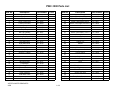
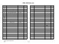
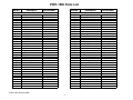
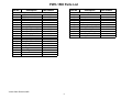
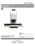
PWC – 500/1000/1010/1500
PureWaterCooler
SERVICE MANUAL
for
PureWaterCooler™
by Vertex
Model PWC-500/1000/1010/1500
P/N man-7008
Copyright 2006 Vertex Water Products
PWC – 500/1000/1010/1500
PureWaterCooler
Table of Contents
•
•
•
•
•
•
•
•
•
•
•
•
•
•
•
•
•
•
Introduction
Cooler Set-up
Remove Top Cover
Remove/Replace Float
Remove/Replace Hot Tank
Faucet Repair
Hot Tank Reset Button
Remove/Replace Hot Tank Thermal Sensors
Cold Temperature Adjustment
Drain Cooler Tanks
Remove/Replace Cold Temperature Switch and Sensor
Sanitization Procedure
Trouble Shooting
PWC-1010 Version
Specifications
Cooler Exploded View
Parts List
Schematics
Copyright 2006 Vertex Water Products
PWC – 500/1000/1010/1500
PureWaterCooler
PWC-1000 Cooler
1. Introduction
The PWC-1000 line of point of use coolers are designed to give years of reliable service
The cooler has 2 spigots that dispense filtered water at 2 different temperature levels – hot
and cold temperature water. The main (cold-temp) tank holds one gallon of water and is
constructed of stainless steel. The cold tank can be accessed for servicing the float
mechanism and for cleaning by removing the cooler main top cover (see section 4).
The hot tank is made of stainless steel and holds ½ gallon. It is important not to turn on the
hot tank when there is no water in it as this will damage the heating element.
The compressor is a sealed unit and is not serviceable in the field. The compressor can be
replaced by a qualified refrigeration technician with proper tools and equipment.
Please consult the factory if the compressor needs servicing.
CAUTION: If the compressor has been stopped by switching it off or unplugging power,
WAIT 10 MINUTES before turning the compressor on again. The compressor may stall
and burnout if powered back on without waiting.
The cooler makes clean water by filtration or by the reverse osmosis process. Water enters the
back of the cooler and then passes through the filtration system. A feed water ball valve is
Located near the filters and must be turned to the on position to allow the unit to make water.
Electrical power is not required for the cooler to make purified water. CAUTION: The carbon
filtration versions of the cooler (PWC-1000F) should not be used with water hardness over
7 grains because of lime scale build up on the heating element. If hardness is higher than
7 grains, softening of the feed water is recommended or another option is to install
a “phosphate” filter to the filter system.
Copyright 2006 Vertex Water Products
PWC – 500/1000/1010/1500
PureWaterCooler
2. Cooler Set-Up (for new cooler installation)
Feedwater/Drain Connections
-Feed Connection
2.1 Open hinged door to access filter
compartment
2.5 Remove feed water plug (orange) from back
of cooler.
2.6 Connect supplied orange feed water tubing to
feed connector on back of cooler.
Copyright 2006 Vertex Water Products
PWC – 500/1000/10101500
PureWaterCooler
2. Cooler Set-Up cont.
2.4 Make feed water connection to cold water line.
A self piercing saddle valve is provided.
Feedwater connection (RO & filtration coolers)
(For use on copper tubing)
Use supplied self piercing saddle valve.
Connect to water inlet on cooler using 1/4”
tubing. Clamp saddle valve over copper feed
water line (cold water line only). Tighten
needle valve until tube is pierced. Retract
needle 1 -2 turns to start water flow.
2.5 Flushing carbon fines from carbon filter.
Most carbon filters have fine particles of
carbon material in the filter that will be
swept into the water stream when the first
water flows through the filter. Although not
harmful, these carbon fines in the water are
unsightly. Flush the carbon fines out of the
filter before filling cooler tanks with the
following procedure.
2.6 Remove outlet line of carbon filter (bottom)
2.7 Attach 3 feet of ¼” tubing to the carbon filter
outlet port (flush tubing)
2.8 Place flush tubing in bucket to catch water
carbon fines.
Copyright 2006 Vertex Water Products
PWC – 500/1000/1010/1500
PureWaterCooler
2. Cooler Set-Up cont.
2.9 Turn on feed water at source and turn ball valve
at filter to “on” to let the water flush the filter.
2.10 Flush until water flows clear (1 – 2 gallons)
2.11 Remove flush line. Reconnect tank line to
outlet of carbon filter
2.12 WARNING: Do not turn on cooler hot power
until cooler tanks are full of water.
Figure 2.7
-Drain Connection
2.9 Drain Connection (for units equipped
with RO)
2.10 Remove drain plug (black) from back of
cooler
2.11 Connect supplied black water tubing to
drain connector on back of cooler
2.12 Attach supplied drain saddle to a
standard 1 ½” drain pipe see fig. 1 below
Drain saddle connection method
Drain connection required only for cooler with reverse osmosis filtration
Figure 1
RO filter set showing autovalve.
The autovalve automatically turns off the
water flow when the tanks are full
Copyright 2006 Vertex Water Products
PWC – 500/1000/1010/1500
PureWaterCooler
3. Top Cover Removal
3.1 Remove (2) screws on back of cooler top cover
3.2 Lift cover
3.3 Cold tank is now accessible for cleaning
and servicing other parts of the cooler.
3.4 Reinstall in reverse order
Copyright 2006 Vertex Water Products
PWC – 500/1000/1010/1500
PureWaterCooler
4. Remove/Replace Mechanical Float Valve Assembly
4.1 First, remove top cover. See Section 3
Float Valve/Level Control
4.2 Disconnect tubing from fitting
4.2 Remove elbow connector from float stem
Copyright 2006 Vertex Water Products
PWC – 500/1000/1010/1500
PureWaterCooler
4. Remove/Replace Mechanical Float Valve Assembly
continued
4.3 Remove nut holding float assembly to tank
4.5 Lift out float assembly
Fitting
Nut
washer
Float
Float Assembly Parts
Copyright 2006 Vertex Water Products
PWC – 500/1000/1010/1500
PureWaterCooler
5. Removing/Replacing Hot Tank
5.0 Unplug power from wall
5.1 Drain water from cooler using front
spigots and by removing rear drain plug
5.2 Remove top cover (section 3)
REMOVE FRONT PANEL
5.3 Remove 2 top screws from front of panel
5.4 Remove 2 screws from bottom of panel.
5.5 Remove 2 screws from back side of front
panel. Requires extra long Phillips-head
screwdriver.
5.6 Hold front panel
in hand.
Copyright 2006 Vertex Water Products
PWC – 500/1000/1010/1500
PureWaterCooler
•
Removing/Replacing Hot Tank
Cont.
5.7 Disconnect electrical connector at circuit board.
5.8 Hot tank is now accessible
5.9 Remove silicon tubing – 4 places
5.10 Disconnect 2 electrical connectors at bottom
of tank
5.11 Remove (1) hot tank screw from below
Copyright 2006 Vertex Water Products
PWC – 500/1000/1010/1500
PureWaterCooler
•
Removing/Replacing Hot Tank
Cont.
5.12 Remove (1) hot tank screw from above.
5.13 Pull hot tank down
5.14 Disconnect (4) electrical connectors
from hot tank temperature sensors.
5.15 Hot tank can now be removed.
5.16 To replace the hot tank, reverse the
above procedure.
Copyright 2006 Vertex Water Products
PWC – 500/1000/1010/1500
PureWaterCooler
•
Dispensing Faucet Repair
6.1 Remove top cover of cooler (section 3)
6.2 For most faucet problems, the working mechanism
of the faucet can be replaced without having to remove
the entire faucet from the cooler. The faucet body
is a one piece molded plastic part that usually does
not need replacing.
6.3 To remove the working mechanism of the faucet, reach
in from the top and unscrew the top nut of the faucet
mechanism.
6.4. Lift out the faucet mechanism from the faucet body.
Copyright 2006 Vertex Water Products
PWC – 500/1000/1010/1500
PureWaterCooler
•
Faucet Repair
Cont.
6.4 Lift out the lever assembly. Obtain a new
lever assembly and install in the faucet
base. Hand tighten the lever assembly
securely.
6.5 Fill the cooler with water and check for leaks
(shown with front panel removed)
Button
Seal
Note:
When removing and replacing the lever assembly,
make sure the rubber seal and the lever are
connected together. To connect the seal to the lever
assembly, firmly push the seal on to the
button on the lever assembly.
6.6 Reinstall the top panel.
Correctly connected seal/lever assembly
Copyright 2006 Vertex Water Products
PWC – 500/1000/1010/1500
PureWaterCooler
7. Hot Tank Reset Button
7.0 Observe that there are two circular sensors
attached to the hot tank. The lower one is the
main controller at 82 ºC and the upper senor
is the over-temp cut off.
The power switch for the hot tank (at the back
of the cooler) should not be turned on until
water can be dispensed from the hot spigot. If
the hot power is turned on without water in the
hot tank the heating element will over heat. To
prevent this, the upper thermal sensor on the
hot tank will cut power to the heating element
before any damage takes place. If this happens
the switch on the thermal sensor can be reset to
operational mode manually by the following
procedure.
7.1 Make sure the power cord is unplugged.
7.2 From the back of the cooler, find the hot tank
7.3 Find the upper thermal sensor on the hot tank
7.4 Using a long thin object such as a screw driver
or a pen, depress the small black button at the
center of the upper thermal switch. You should
feel a click when you depress the button. This
action resets the over-temp sensor.
Copyright 2006 Vertex Water Products
PWC – 500/1000/1010/1500
PureWaterCooler
8. Remove/Replace Thermal Sensor
8.0 The hot tank thermal sensors are located
on the outside of the hot tank. There are
two thermal sensors. The sensor located
lower on the hot tank controls the daily
operation of the heating element. The
upper thermal sensor is an overheat
safety switch and cuts power to the hot
tank should a malfunction occur and
the tank starts to overheat.
8.1 Unplug cooler from power source for
this operation.
8.2 Remove (2) screws holding the upper
part of the cooling grill to the cooler
cabinet. Keep the rubber grommets
for reassembly.
8.3 Carefully pull the cooling grill away
from the cooler. The grill is still attached
at the bottom. Do not move the grill
more than 30 degrees away from the
cooler frame or the cooling system may
be damaged.
30 degrees
Max
Copyright 2006 Vertex Water Products
PWC – 500/1000/1010/1500
PureWaterCooler
•
Remove/Replace Thermal Sensor
cont.
8.4 There are (2) thermal sensors attached with
screws to the hot tank. The lower sensor automatically turns the heating element on and off
to maintain the water at 180 ºF. The upper
sensor is the over temperature sensor. This
sensor activates if the temperature on the tank
goes over 212 ºF. If this sensor is activated due
to a overheat condition, it will cut the power to
the heating element. If this happens, it can be
reset by pressing the button at the center of
the sensor.
To check if either thermal sensor is good, use a
continuity tester (ohm meter) to check for
continuity across the thermal sensor. Make
sure the thermal sensor is at ambient temperature
for this test. If there is no continuity, replace
the sensor.
8.5 To change either sensor, disconnect (2)
electrical terminals from sensor.
8.6 Remove (2) screws holding sensor to tank.
8.7 Install new thermal sensor, replace screws,
reconnect electrical terminals to sensor.
8.8 Carefully relocate cooling grill to original
location and re-attach using rubber grommets
and screws.
Copyright 2006 Vertex Water Products
PWC – 500/1000/1010/1500
PureWaterCooler
9. Cold Tank Temperature Adjustment
9.0 The cold water temperature adjustment
is located on the back of the cooler on
the right side. An expansion tube senses
temperature in the cold tank and open
and closes the thermostat.
9.1 The cold adjustment is a shaft with a
screw driver slot on the end.
9.2 To make the water colder, using a
screw driver, rotate the shaft clockwise.
For warmer water rotate the shaft
counter clockwise. There are stops on
the adjustment shaft. DO NOT force
the control shaft over the stop. If this
happens, it will be necessary to replace
the temperature controller
270º Travel
STOP
WARMEST
COLDEST
STOP
Normal Travel is 270º
Copyright 2006 Vertex Water Products
PWC – 500/1000/1010/1500
PureWaterCooler
10. Draining Cooler Tanks
Completely draining the tanks is required when shipping the cooler
or when one the of the tanks needs replacing. This procedure will
allow you to remove all the water from the cooler.
9.0 Hot and Cold Tank Drain: Using a flat head
screw driver, pry the hot tank plug out until
you can grasp it with your fingers.
9.1 Remove the plug with fingers.
Water will pour from the port
9.2 Drain any remaining water in the
system by depressing the faucets.
Copyright 2006 Vertex Water Products
PWC – 500/1000/1010/1500
PureWaterCooler
11. Remove/Replace Cold Tank Sensor
11.0 The cold tank sensor is extremely reliable
and rarely needs replacing. Its function
is to control the cold water temperature by
turning the compressor on or off as needed.
11.1 Remove the top cover of the cooler (sec. 3)
11.2 Remove the float assembly )sec. 4)
11.3 Remove the silicon rubber sealing ring
11.4 Remove the silicon over flow tube
11.5 Carefully lift off the insulting foam
from the cold tank
Copyright 2006 Vertex Water Products
PWC – 500/1000/1010/1500
PureWaterCooler
•
Remove/Replace Cold Tank Sensor
cont.
11.6 Cold tank cooling coils and sensor probe
are now visible
11.7 Disconnect (2) wires from sensor switch
11.8 Remove (2) screws holding sensor switch
body to cooler cabinet.
Copyright 2006 Vertex Water Products
PWC – 500/1000/1010/1500
PureWaterCooler
•
Remove/Replace Cold Tank Sensor
cont.
11.9 Remove cold sensor switch and sensor tube
from cooler
11.10 To remove the sensor tube, carefully pull the
sensor out of the copper tube at the bottom
outside of the cold tank
11.11 With new cold sensor, carefully install sensor
tube into copper tube at bottom of cold tank.
11.12 Install the sensor switch using (2) screw to
cooler cabinet.
11.13 Adjust sensor tube so it is routed close to the
outside of the cold tank. This will allow the
insulating foam to fit properly over the tank.
11.14 Reinstall insulating foam.
11.15 Reinstall remaining parts in reverse order.
Copyright 2006 Vertex Water Products
PWC – 500/1000/1010/1500
PureWaterCooler
12. Sanitization Procedure
The sanitization procedure is performed to reduce/eliminate any bacteriological
growth in the cooler tanks and dispensing plumbing. Bacteriological growth
can be the cause of some taste and odor in the water.
The procedure is as follows:
•
•
•
•
•
•
•
•
•
•
Mix 1 teaspoon of common household bleach (5.25%) in 2 gallons of
clean water.
Unplug the cooler from the power source.
Drain all water from the cooler tanks.
Pour the sanitizing solution into the main (cold temperature) tank until full.
Open all spigots to allow sanitizing solution to fill the dispensing faucets.
Close the spigots.
Let the sanitizing solution stand in the cooler for 10 minutes.
CAUTION: Leaving the sanitizing solution in the cooler for more
than 10 minutes can cause taste problems in the water.
Completely drain the sanitizing solution from all the tanks per section 10
Fill the main (cold temp.) tank with clear tap water to rinse out the
sanitizing solution.
Completely empty the rinse water from the tanks.
The cooler is now sanitized and ready for filling with filtered water.
Copyright 2006 Vertex Water Products
PWC – 500/1000/1010/1500
PureWaterCooler
13. Trouble Shooting
Water not cold from cold tank
(Water dispenses from spigot but is not cold)
Solution
Possible causes
1. Cooler not plugged in
.
Make sure power cord is plugged
into wall socket
2. Power switch not on
Make sure cold power switch on
the back panel is on.
3. Adjust temperature control
The thermostat temperature control
adjustment is located on the back
of the cooler. (see section 9)
4. All cold water has been drained Cooler needs time to recover.
wait 10-15 minutes until water cools
Copyright 2006 Vertex Water Products
PWC – 500/1000/1010/1500
PureWaterCooler
13. Trouble Shooting
Cont.
No Hot Water from Hot Tank
Possible Causes
Solution
1. Cooler not plugged in
Make sure power cord is plugged
into wall socket
2. Power switch not on
Make sure Hot power switch on back
panel is on and hot power light on
front is illuminated
3. Electrical terminal
disconnected
Check to see that both wires are
connected to the heating element
terminals. These are located at the
bottom of the hot tank
4. Heating element failure
due to scaling
Check for continuity across hot tank
heater terminals. To do this, unplug
unit from wall power. Disconnect one
of the connector at the heating element
terminals (at bottom of tank). Using
an ohm meter, check for continuity
across the 2 terminals. If there is no
continuity (open), the tank must be
replaced.
Copyright 2006 Vertex Water Products
PWC – 500/1000/1010/1500
PureWaterCooler
13. Trouble Shooting Cont.
No Hot Water from Hot Tank
Possible causes
Solution
cont.
.
5. Thermal sensor failure
The thermal sensors are attached to the
hot tank. The upper sensor is a 96 ºC
sensor and functions as an over heat
safety. The lower sensor is a 82 ºC
sensor and controls the heating element
function. The lower sensor would be the
problem if there was no hot water. To
see if the sensor is functioning properly,
first unplug the cooler from the wall.
remove the terminal from the sensor.
Using an ohm meter, check for continuity
If there is no continuity (open), replace
sensor as per section 8.
6. Hot tank turned on without
water in tank
The hot power should never be turned on
without water in the tank. If this happens,
the upper thermal sensor on the hot tank
will switch, cutting power to the hot tank.
This is a safety device to prevent the heating
element from burning itself out due to dry
heating. Once the hot tank cools off the
switch can be reset to operating condition.
See section 7.
Copyright 2006 Vertex Water Products
Trouble Shooting Cont.
No Hot Water from Hot Tank
cont.
An indicator of a hot tank problem can also be the lights on the front
control panel. Below is a table of trouble shooting help.
If the Hot Tank is not heating and the front panel lights are:
Front Panel Lights
Cause
Check
Hot Power – on
Heating
- on
Heating element disconnected
or burned out
No Continuity across
heating element Replace Hot Tank
No lights at all
Upper thermal sensor Reset
button disengaged or sensor
burned out
Press reset button /
NO Continuity across
thermal sensor -replace
sensor
Hot Power – on
Heating
- off
Lower thermal sensor
disconnected or burned out
No Continuity across
thermal sensor - replace
sensor
PWC – 1000/1010
PureWaterCooler
14. Model PWC-1010
The model PWC-1010 has room and cold temperature water dispensed from the
two spigots. Nearly all functions and construction of the PWC-1010 cooler are
the identical to the PWC-1000 (hot and cold) cooler except as follows:
1. There is no heating element in the room temperature holding tank
2. There are no power switches on the back of the cooler
3. The cold power (compressor) turns on as soon as the cooler is plugged in.
4. The indicator lights on the front of the cooler show when there is power
to the compressor (cold power) and when the compressor is on (cooling).
All repair sections of this manual apply to the model PWC-1010 cooler. To
remove and replace the room temperature tank refer to the section covering the
hot tank in this manual (section 5).
Copyright 2006 Vertex Water Products
PWC – 1000/1010
PureWaterCooler
15. Specifications
PWC-1000
PWC-1010
Voltage/Frequency
120 VAC/ 60 Hz
120 VAC/ 60 Hz
Weight (dry)
48 lbs.
48 lbs.
Total Water Capacity
Hot tank
Cold tank
Room tank
1.5 gallons
.5 gallons
1.0 gallons
1.5 gallons
Power Consumption Total
Hot Tank
Cold Tank
Room Tank
Temperature
Hot
Cold (adjustable)
600 Watts
500 Watts
100 Watts
180 ºF average
38 ºF average
38 ºF average
Refrigerant
R134a 36 mg.
R134a 36 mg.
Copyright 2006 Vertex Water Products
1.0 gallons
.5 gallons
100 Watts
100 Watts
0 Watts
PWC-1000F/1010F Filtration Configuration
p/n ifa-4034
p/n ifa-4035
Sediment
Carbon
To Cooler
Tanks
Feed Water In
Flow restrictor
In line here
PWC-1000R/1010R RO Filtration Configuration
p/n mhsa-1103
(membrane housing)
p/n ma-4203
(membrane element)
Sediment
Carbon
Membrane
To Cooler
Tanks
Out
p/n avqc-1303
Autovalve
Feed Water In
In
p/n ifa-4034
p/n ifa-4035
Clean Water
Drain
Bulkhead Fitting
Cold switch
brown
blue
Fuse
Compressor
Cold thermostat adjustment
Hot switch
white
blue
red
white
Circuit board/
Indicator panel
Hot Tank
yellow
white
red
yellow
96 oC
82 oC
Thermal Sensors
red
yellow
yellow
yellow
VERTEX
Wiring Diagram
Water Products
For PWC-1000 Cooler
Montclair, California
None
Scale
CL1-10001
Dwg. No.
10/10/05
Date
Used on.
PWC-500-1500
PWC-1000 Parts List
Item No.
Description
1
2-1
3
4
5
6
7
8
9
10
11-1
12
13
14
15
16
17
18
19
20
21
22
23
24
25
26
27
28
29
Top Cover
Dust Cover
Upper Front Panel
Lower Front Door
Base
Drip Tray Base
Drip Tray
Hot Tap w/Safety
Cold Tap
Indicating Panel (sticker)
Main Water Tank Cover
Left Side Panel
Right Side Panel
Bracket
Insulating Sleeve
Spring Clip
Screw 4 x 8 black
Mounting Plate
Compressor
Mounting Plate
Faucet Bracket
Bottom Insulator
Upper Insulator
Cold Water Tank
Silicon Gasket
VERTEX WATER PRODUCTS
2005
Part Number
cl1cl1cl1cl1cl1cl1cl1cl1cl1cl1cl1cl1cl1cl1cl1cl1cl1-
cl1cl1cl1cl1cl1cl1cl1-
Price
9200
9201
9202
9203
9204
9205
9206
9207
9208
9209
9210
9211
9212
9213
9214
9215
9216
9217
9218
9219
9220
9221
9222
9223
cl1- 9224
1 of 2
Item No.
Description
Part Number
30
31
32
33
34
35
36
37
38
39
40
41
42
43
44
45
46
47
48
49
50
Silicon Vent "T"
Silicon Tube Straight 250 x 2
Silicon Tube Elbow 160 x 4
Silicon Tube Elbow 50 x 60 x 4
Hot Tank
cl1cl1cl1cl1cl1-
9225
9226
9227
9028
9029
Silicon Tube Elbow, 175 x 4
Screw, 3 x 8
Vertex Emblem
Mechanical Float Valve
Tubing, 1/4"
Handle
cl1cl1cl1cl1cl1cl1-
9230
9231
9232
9233
9234
9235
52
53
54
55
56
57
58
Cold Tank Outlet Connector
Tap Nut
Silicon Tube SL-04
Screw, Hot Tank
Rear Cover
Cold Temperature Switch
Power Switch
cl1- 9236
cl1- 9237
cl1- 9238
Condenser
Drain Fitting Nut
Dryer
cl1- 9239
cl1- 9240
cl1- 9241
Tank Drain Connector
Strain Relief
cl1cl1cl1cl1-
9242
9243
9244
9245
cl1- 9246
cl1- 9247
Price
PWC-1000 Parts List
Item No.
59
60
61
62
63
64
65
66
67
68
69-1
70
71
72
73
74
75
Description
Part Number
Drain Plug
Rubber Pad
cl1- 9248
cl1- 9249
96 C Temperature Sensor
82 C Temperature Sensor
Fuse Housing
cl1- 9250
cl1- 9251
cl1- 9252
PC Board
Screw, 4 x 12
Screw, 4 x 25
Screw, 4 x 7
Screw, 5 x 22
Screw, 3 x 4
VERTEX WATER PRODUCTS
2005
cl1cl1cl1cl1cl1cl1-
Price
9253
9254
9255
9256
9257
9258
6/5/2005
2 of 2
PWC-1500 Parts List
Item No.
Description
Part Number
P1
P2
P3
P4
P5
P6
P7
P8
P9
P10
P11
P12
P13
P14
P15
P16
P17
P18
Main Tank Cover, round
Top Cover, square
Upper Front Panel
Lower Front Panel
Faucet Cover
Base
Drip Tray Set
Handle
Faucet, Cold Water
Faucet, Hot Water
Strain Relief
cl1
cl5
cl5
cl5
cl5
cl5
cl5
cl1
cl5
cl5
9210
9600
9601
9602
9603
9604
9605
9235
9606
9607
Nut, Faucet
Rubber Pad
1/4" tubing
cl5
cl1
9607
9249
Dust Cover
Fitting, elbow, 1/4 x 1/4
cl1
cl5
9201
9608
E1
E2
E3
E4
E5
E6
E7
E8
PC Board
Cold Temperature Switch
Power Switch
Fuse Housing
Fuse
Screw, 4 x 6
Compressor
Power Cord
cl1
cl1
cl1
cl1
9253
9237
9238
9252
cl1
cl1
9256
9218
Item No.
M1
M2
M3
M4
M5
M6
M7
M8
M9
M10
M11
M12
M13
M14
M15
M16
M17
M18
M19
M20
O1
O2
O3
Vertex Water Products 2006
1
Description
Upper Plate
Mounting Plate
Left Side Panel
Right Side Panel
Rear cover
Part Number
cl5
cl1
cl5
cl5
cl1
9609
9217
9610
9611
9236
cl5
cl1
9612
9241
Spring Clip
cl1
9215
Screw, 5 x 22
Screw, 4 x 25
Screw
Screw, 3 x 8
Screw, 4 x 12
Pivot Pin
cl1
cl1
cl5
cl5
cl5
cl5
9257
9255
9613
9614
9615
9616
Indicating Panel, (sticker)
cl5
9622
Mechanical Float Valve
cl1
9233
Hotlock Safety tab
cl5
9623
Screw
Screw
Condensor
Dryer
Capillary Tube
PWC-1500 Parts List
Item No.
H1
H2
H3
H4
H5
H6
H7
H8
H9
H10
H11
H12
H13
H14
H15
H16
H17
H18
Description
Part Number
Hot Tank
96ºC Temperature Sensor
82ºC Temperature Sensor
Screw 5 x 22
cl5
cl1
cl1
cl1
9617
9250
9251
9257
Screw, Hot Tank
Silicon Tube Elbow, 175 x 4
Silicon Tube Elbow, 160 x 4
Silicon Tube St, 5 x 250
Silcon Vent "T" Tube
cl1
cl1
cl1
cl5
cl1
9245
9230
9227
9618
9225
Silicon Tube Elbow 50x60x4
Drain Fitting Nut
Tank Drain Connector
Drain Plug
Sillicon Plug
cl1
cl1
cl1
cl1
cl5
9028
9240
9246
9248
9619
Item No.
C1
C2
C3
C4
C5
C6
C7
C8
C9
C10
C11
Vertex Water Products 2006
2
Description
Part Number
Cold Water Tank
cl1
9223
Silicon Gasket
Cold Tank Outlet Connector
cl1
cl1
9224
9242
Nut, Faucet
Insulating Foam, Cold Tank
Bottom Insulating Foam
cl5
cl1
cl5
9620
9222
9621
Silicon Tube Elbow, 75 x 4
Insulating Sleeve
cl1
cl1
9244
9214
ÂÅ
ÂÅ
¶À
¶À
¶À
¬õ
¶À
¥Õ
¶À
¬õ
¥Õ
ÂÅ(*)
´Ä
ÂÅ(*)
ÂÅ
¥Õ
´Ä
ÂÅ
¥Õ