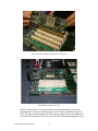
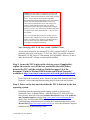
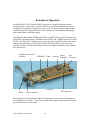
1
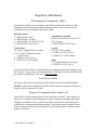
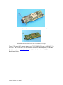
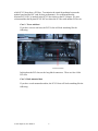
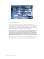
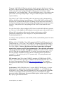
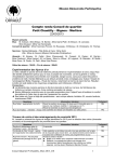
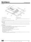
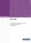
Guide to Myrinet/PCI-X Network Interface
Cards
Hardware & Software Installation
Principles of Operation
Myricom, Inc.
Date: 11 March 2005
The most recent version of this document can be downloaded from
http://www.myri.com/scs/doc/guide_to_pcix_nics.pdf
© 2005 Myricom, Inc. DRAFT
1
Regulatory Information
Electromagnetic Compatibility (EMC)
Myrinet-Fiber (M3F) network interface cards (NICs) and their fiber cables are fully
compliant with the following standards and specifications for the emission of and
susceptibility to electromagnetic interference (EMI):
European Union
® BS EN55024 (1998)
® BS EN61000-3-2 (2001)
® BS EN61000-3-3 (1995) W/A1:98
® BS EN55022 (1998) Class A
Australia/New Zealand
AS/NZS 3548 (1005 W/A1 & A2: 97)
Class A using:
® BS EN55022 (1998) Class A
Canada
ICES-003 Class A using:
® CISPR 22 (1997) Class A
® ANSI C63.4 (1992) method
United States
FCC Part 15 Subpart B Class A using:
® FCC Part 15 Subpart B Section
15.109 Class A
® CISPR 22 (1997) Class A
® ANSI C63.4 (1992) method
Japan
VCCI (April 2000) Class A using:
® CISPR 22 (1997) Class A
On the basis of these EMC certifications and other engineering data, these products carry
the CE mark. A copy of the current Declaration of Conformity can be found linked from
the product specifications on the web at www.myri.com.
Laser Device Safety
The optical-fiber transceivers used in the M3F family of products are Class I Laser
Products. Optical-fiber components with this classification pose no threat of biological
damage, and are considered to be safe.
Disposal of Components that Contain Lead
Myrinet NICs contain small quantities of lead in the tin-lead solder. Please dispose of
them safely. Disposal of lead-containing electronic components through regular trash
channels is prohibited in many countries and regions, because the lead leached out of
landfills may contaminate groundwater supplies. Myricom has proper channels for the
disposal of these materials, and will dispose of any Myrinet products returned for that
purpose to Myricom.
© 2005 Myricom, Inc. DRAFT
2
Introduction
Myricom currently produces three series of Myrinet/PCI-X Network Interface Cards
(NICs): the PCIXD series with 225MHz RISC and memory, and the PCIXE series and
PCIXF series with 333MHz RISC and memory. These series of NICs have the “low
profile PCI Short Card” form factor. The product codes follow this scheme:
Physical Port
M3F- (Myrinet-Fiber)
M3F2- (Myrinet-Fiber)
M3F- (Myrinet-Fiber)
Form factor
PCIX
PCIX
PCIX
NIC type
D
E
F
Memory
-2, -4
-2, -4
-2, -4
such that, for example, a M3F-PCIXD-2 NIC has one Myrinet-Fiber port, has the
Myricom Lanai XP processor operating at 225MHz, and has 2MB of local memory. A
M3F2-PCIXE-2 NIC has two Myrinet-Fiber ports, has the Myrinet Lanai 2XP processor
operating at 333MHz, and has 2MB of local memory. A M3F-PCIXF-2 NIC has one
Myrinet-Fiber port, has the Myricom Lanai 2XP processor operating at 333MHz, and has
2MB of local memory. Not all combinations are produced. The NICs that are in current
production are listed at:
http://www.myri.com/myrinet/full_product_list.html
This listing also includes prices and links to the detailed product specifications.
The low profile PCI short cards, as pictured below, are available with Myrinet ports for
Myrinet-Fiber (LC-connectorized 50/125 multimode fiber cables). (Note that PCIXD
NICs shipped between May 2003 and February 2005 are based on the Lanai-XP chip and
its memory operating at 225MHz. Later production of PCIXD NICs is based on a Lanai2XP chip and its memory operating at 225MHz. The two versions of PCIXD NICs are
form+fit+function equivalent.)
M3F-PCIXD-2 Myrinet-Fiber / PCI-X NIC with a standard PCI faceplate
© 2005 Myricom, Inc. DRAFT
3
M3F2-PCIXE-2 two-port Myrinet-Fiber / PCI-X NIC with a standard PCI faceplate
M3F-PCIXF-2 Myrinet-Fiber / PCI-X NIC with standard PCI faceplate
These PCIX-series NICs operate in hosts with 75-133MHz PCI-X slots or 66MHz (3.3V)
PCI slots. The PCIXD NICs are also available as host-card adaptors (HCA) for the IBM
BladeCenter. Contact [email protected] for additional information on the IBM
BladeCenter HCAs.
© 2005 Myricom, Inc. DRAFT
4
Identification on each Myrinet/PCI-X NIC
Product code
Serial number
Ethernet MAC
address
The label on a Myrinet/PCI-X NIC
A label similar to that above appears on the underside of every Myrinet/PCI-X NIC. This
label contains the product code, the serial number, and the Ethernet MAC address.
Please provide this information in any correspondence with Myricom support
([email protected]).
Installation
As a first step in using Myrinet technology, you must install the Myrinet/PCI-X NICs
into your hosts. Installation instructions vary depending on the characteristics of your
host: (1) tower unit host, or (2) rack-mounted host. If you have (1), you will need to use
the standard PCI faceplates, and if you have (2), you will need to use low-profile PCI
faceplates. Standard or low-profile faceplates must be specified at the time of order.
The NICs should be handled gently, preferably by the front panel or card edges. The
front panel of the NIC is the metal plate or molding (as can be seen on the photos above)
that contains two LEDs and the port connector(s). Directions for installation are as
follows:
Step 1: Power off the host to which you will be installing the NIC(s).
Remove the exterior covering of the machine, and locate the PCI-X
slot(s).
Note: Refer to the hardware specifications for the mother board to locate the PCI-X slots
(and distinguish a 64-bit PCI-X slot and a 64-bit PCI slot). If the mother board has more
than one PCI-X slot, identify which PCI-X slot(s) run at maximum speed (133MHz), and
© 2005 Myricom, Inc. DRAFT
5
which PCI-X slots share a PCI bus. To minimize the signal degradation between the
mother board and the NIC (and for best performance), we recommend that the
Myrinet/PCI-X NIC is inserted in the PCI-X slot closest to the PCI chipset. We also
recommend that the Myrinet/PCI-X NIC not share the PCI bus with another PCI device.
Case 1: Tower unit host
If you have a tower unit host, the PCI-X slots will look something like the
following:
PCI slot (64-bit)
In this photo the PCI slots are the long black connectors. There are four 64-bit
PCI slots.
Case 2: Rack-mounted host
If you have a rack-mounted machine, the PCI-X slots will look something like the
following:
© 2005 Myricom, Inc. DRAFT
6
PCI-X slots on a rack-mountable mother board
In this photo, there are 6 PCI-X slots. One of the PCI-X slots is green, and the
remaining five PCI-X slots are white connectors.
Step 2: Insert the Myrinet/PCI-X NIC into a PCI-X slot.
Case 1: Tower unit host
With a tower unit host, a low-profile PCI-short-card Myrinet/PCI-X NIC with a
standard PCI faceplate is installed in a PCI-X slot. If your host has more than one
PCI-X slot, we recommend that the Myrinet/PCI-X NIC is inserted into the PCI-X
slot closest to the PCI chipset. For best performance, the Myrinet/PCI-X NIC
should be inserted into a PCI-X slot that runs at maximum speed (133MHz) and
should not share the PCI bus with another PCI device. Inasmuch as some PCI
connectors are more close-fitting than others, you may need to push quite hard on
the front panel and the edge of the card to seat the card securely.
© 2005 Myricom, Inc. DRAFT
7
Installed NIC in a PCI-X slot
Case 2: Rack-mounted host
If the rack-mounted host is a 2U or larger, the low-profile PCI-short-card
Myrinet/PCI-X NIC with low-profile PCI faceplate may not require a riser card
for installation. If at all possible, avoid the use of a riser card. If you must use a
riser card and the riser card has multiple slots, insert the Myrinet/PCI-X NIC into
the riser card slot closest to the PCI-X slot on the mother board.
We recommend the PCI-X slot closest to the PCI chipset for the installation of the
Myrinet/PCI-X NIC. For best performance, the Myrinet/PCI-X NIC should be
inserted into a PCI-X slot that runs at maximum speed (133MHz) and should not
share the PCI bus with another PCI device. Note that some vendors ship their
mother boards with the speed of the PCI-X slots reduced, and you must manually
adjust the jumper next to the PCI-X slots to run at full speed. (In the following
pictures, the jumper is blue and located on the left side of the PCI slots.) Refer to
the hardware specifications of the mother board for details of the PCI slots.
© 2005 Myricom, Inc. DRAFT
8
Insertion of NIC (without riser card) into a PCI-X slot
Installed NIC (without riser card)
However, since space is very restricted in a 1U rack-mounted host, if the rackmounted host is a 1U host, the Myrinet/PCI-X NIC must be installed with a riser
card. The riser card is inserted on the PCI connector side of the card, and the riser
card is then inserted into a PCI slot (as shown in the following photograph). If you
© 2005 Myricom, Inc. DRAFT
9
must use a riser card and the riser card has multiple slots, insert the Myrinet/PCIX NIC into the riser card slot closest to the PCI-X slot on the mother board.
Inasmuch as some PCI connectors are more close-fitting than others, you may
need to push quite hard to get the card to seat securely.
Installed NIC (with attached riser card)
Installed NIC (with riser card)
© 2005 Myricom, Inc. DRAFT
10
Caution: If at all possible, avoid the user of a riser card.
Although PCI riser cards are commonly used, they will
generally violate PCI specifications for the length of signal
traces. A riser card may also introduce impedance
discontinuities and signal degradation between the mother
board, riser card, and network interface card. If you
observe PCI-communication errors when using a riser
card, see if the problem persists when you plug the
Myrinet/PCI-X NIC directly into the PCI slot. A higher
quality riser card -- one whose traces match the impedance
of signals on the mother board and NIC -- may also solve
the problem.
Also, it is important that a 64-bit riser card be used in a
64-bit PCI slot, and likewise a 32-bit riser card should be
used in a 32-bit PCI slot. Otherwise, the Myrinet/PCI-X
NIC will not be correctly detected and/or serious
performance irregularities will result.
Note: Inserting a PCI-X NIC into a 64-bit / 66MHz PCI slot
As previously mentioned, the Myrinet/PCI-X NICs support both PCI-X and PCI
protocols, and can be used in any 3.3V PCI slot. Thus, it is possible to insert a
Myrinet/PCI-X NIC into a PCI slot running at 64-bit/66MHz. However, if this is
done, the 64-bit NIC will run at reduced speed (66MHz).
Step 3: Secure the NIC in place with a locking screw (if applicable),
replace the exterior cover of the host, and attach the cable (Fiber)
between the NIC and the switch (as detailed on pages 3-4 of the
document “Guide to Myrinet-2000 Switches and Switch Networks,”
available at http://www.myri.com/myrinet/m3switch/guide/index.html).
Please follow the instructions in the “Guide to Myrinet-2000 Switches and Switch
Networks” when connecting/disconnecting cables to/from cards and switches.
Step 4: Power on the host and check that the NIC is detected by the host
operating system.
Depending upon the operating system running on the host, this detection
mechanism varies, as detailed below. After the Myrinet PCI-X/Host NIC has
been correctly detected, refer to the Software Download section of the Software
and Customer Support webpage (http://www.myri.com/scs/#downloads) for
details of the recommended software and installation instructions.
Troubleshooting information can be found in the Troubleshooting section of the
Myrinet FAQ (http://www.myri.com/scs/FAQ) as well as the document "Myrinet
Installation and Troubleshooting Guide".
© 2005 Myricom, Inc. DRAFT
11
Linux
If your host is running Linux, you can issue the command /sbin/lspci, which will
return all devices attached to the PCI bus.
Screen image of /sbin/lspci command.
If the output you receive is similar to that above, namely you see the “Network
controller: MYRICOM Inc” entry, the Myrinet/PCI-X NIC has been correctly
detected. The card ID for the Myrinet/PCI-X NIC is 8043, the (rev 04) denotes a
PCIXD NIC, and the (rev 05) denotes a PCIXE NIC. If you see (rev 06) in the
output, the host has detected a PCIXF NIC. You can now proceed to the software
installation.
© 2005 Myricom, Inc. DRAFT
12
Windows 2000 and Windows XP
For Windows 2000 and Windows XP, a “Found New Hardware” dialog box (as
shown below) will appear when the host detects a new PCI card. Once a
Myrinet/PCI-X NIC has been installed and the host powered on, the appearance
of this dialog box will signal that Windows has detected the network interface
card.
Photo of Dialog Box
© 2005 Myricom, Inc. DRAFT
13
Solaris
If your host is running Solaris, you can issue the command /usr/sbin/prtconf,
which will print the system configuration.
You will see the following text in the output of prtconf.
<…>
pci14c1,8043, instance #0
<…>
This output contains the card ID, 8043, for the Myrinet/PCI-X NIC, and the card
vendor ID for Myricom, 14C1 (as listed in the PCI Vendor registry). If the output
you receive is similar to that above, the Myrinet/PCI-X NIC has been correctly
detected, and you can now proceed to the software installation.
© 2005 Myricom, Inc. DRAFT
14
AIX
If your host is running AIX, issue the command lsdev -Ct gmpci, and you should
see output similar to the following.
<…>
ent2 Available 1V-08 Myrinet GM/Ethernet PCI Adapter
ent3 Defined 1D-08 Myrinet GM/Ethernet PCI Adapter
ent4 Available 1H-08 Myrinet GM/Ethernet PCI Adapter
<…>
Before the GM module is loaded on the host, the Myrinet NICs will be listed as
Defined. As soon as the GM software is loaded on the host, the entry will change
to Available. Be aware that AIX keeps a memory of NICs previously installed in
PCI slots. In this example, the Myrinet NIC previously installed in slot 1D-08 has
since been removed.
© 2005 Myricom, Inc. DRAFT
15
Mac OS X
If your host is running Mac OS X, you can issue the command ioreg, which will
return all devices attached to the PCI bus. An excerpt of the sample output is as
follows:
<…>
||
||
||
||
| +-o USBKeyLargo <class USBKeyLargo>
+-o pci14c1,8043@12 <class IOPCIDevice>
| +-o gm <class gm>
+-o usb@18 <class IOPCIDevice>
<…>
If the output you receive contains the “8043” device, the Myrinet/PCI-X NIC has
been correctly detected, and you can now proceed to the software installation.
© 2005 Myricom, Inc. DRAFT
16
FreeBSD
If your host is running FreeBSD, you can issue the command /usr/sbin/pciconf -l.
Screen dump of /sbin/pciconf –l command
The third column gives the contents of the subvendor id register. The field
consists of the card ID in the upper half of the value and the card vendor ID in the
lower half of the value. The card ID for the Myrinet/PCI-X NIC is 8043, and the
vendor ID for Myricom (as listed in the PCI Vendor registry) is 14c1. In this
example, the host contains one PCIXD NIC (rev=0x04) and one PCIXE NIC
(rev=0x05). If the output you receive is similar to that above, the Myrinet/PCI-X
NIC has been correctly detected, and you can now proceed to the software
installation.
© 2005 Myricom, Inc. DRAFT
17
Principles of Operation
All Myrinet/PCI-X NICs include a RISC processor to execute the Myrinet Control
Program (MCP), local memory, a packet interface to and from the Myrinet port, and a
versatile DMA controller to support zero-copy APIs. Each of these parts supports highavailability and data-integrity features, such as “heartbeat” link-continuity monitoring,
packet checksums, and memory parity.
The difference between the PCIXD and PCIXE or PCIXF NICs is the allowed clock rate
of the RISC and local memory: 225MHz for the PCIXD, and 333MHz for the PCIXE and
PCIXF. The Fiber NICs contain conversion circuitry between the SAN port of the Lanai
chip and the external port. For the Fiber (M3F) NIC pictured below, the conversion
circuitry consists of a SerDes-SAN chip, a SerDes (Serializer-Deserializer) chip, and the
Fiber transceiver.
Serializer-Deserializer
(SerDes)
EEPROM
Lanai
Memory
Power
Test
Regulator Connector
PCIXD NIC
LEDs
PCI connector
Fiber connector
The front panel of the PCI-Short-Card NIC pictured above is the vertical metal plate on
the left-hand side of the NIC. Two LEDs and the cable connector penetrate this PCI front
panel (also known as a face plate).
© 2005 Myricom, Inc. DRAFT
18
The green “link” LED will illuminate when the board is powered, the firmware (such as
the GM-2 or MX-2G Myrinet Control Program) is loaded, and the link is active. The link
will be active if the port is plugged through a cable to a powered switch, to another
initialized NIC or to a loopback plug. The green LED blinks at up to ~5Hz to show when
packet traffic is flowing through the port. The green LEDs on Myrinet-2000 switches
operate similarly.
The yellow “Lanai” LED is controlled by the Lanai processor, and its interpretation is
different for different Myrinet Control Programs. For the GM-2 MCP, the yellow LED
will pulse like a heartbeat while the MCP is running, and will pulse faster when there is
more packet-sending activity (including sending acknowledge packets in reply to packets
received.) If the yellow LED is not pulsing, the GM-2 MCP is not loaded or is not
running.
It is safe electrically to plug or unplug the NIC from the switch while the host is powered
on. However, if you unplug the cable and plug it into another port on the switch or into a
different NIC, the topology of the network changes, and the routes would be
automatically updated by the GM-2 mapper (see “Myrinet Installation and
Troubleshooting Guide”).
A summary of the specifications of the PCIXD, PCIXE, and PCIXF Myrinet/PCI-X NICs
is listed below:
PCI bus: 64-bit, 133/66MHz. These NICs support both PCI-X and PCI protocols, and
can be used in any 3.3V PCI slot. The PCIXD NIC is capable of peak PCI data rates at
the limits of the PCI-X or PCI buses (1067 MB/s for 64-bit, 133MHz PCI-X; 533 MB/s
for 64-bit, 66MHz). However, the data rate to/from system memory will depend
upon the host’s memory and PCI-bus implementation. The achievable performance
can vary greatly from one host PCI chipset to another. These NICs function correctly
in PCI-X slots that are compliant with PCI-X (version 1.0) specifications, and in 3.3V
PCI slots (includes all 66MHz PCI slots) that are compliant with PCI specifications
(version 2.2). The card is keyed for 3.3V operation only. PCI parity generation and
detection is provided.
NIC processor: Lanai XP or Lanai 2XP RISC operating at 225MHz for the PCIXD
NICs, or Lanai 2XP RISC operating at 333MHz for the PCIXE and PCIXF NICs. See
the Lanai-X documentation linked from http://www.myri.com/vlsi/ for a complete
description of the host-DMA, network-DMA, and copy/CRC engines that augment the
RISC.
Local memory: 2MB (256Kx8B) in the -2 version; 4MB (512Kx8B) in the -4 version.
The local memory operates from the same clock as the RISC, i.e., at 225MHz for the
PCIXD NICs, or at 333MHz for the PCIXE and PCIXF NICs, and provides 1,800 MB/s
(PCIXD) or 2,664 MB/s (PCIXE and PCIXF) of memory bandwidth for the RISC
processor, the host-DMA engine, the network-DMA engines, and the copy/CRC engine.
Byte parity is generated and checked.
© 2005 Myricom, Inc. DRAFT
19
EEPROM: 512KB, which includes the PCI-configuration-space data; Vital Product
Data (VPD), including the serial number, MAC address, product code, and other
information; initialization programs; and optional self-test and bootstrap programs. The
EEPROM can be re-programmed by the Lanai-XP/Lanai-2XP.
Myrinet-2000-Fiber port: 2.0+2.0 Gb/s data rate, 2.5+2.5 Gbaud signaling, 8b/10b
encoded Myrinet serial link. An “LC” optical connector attaches to a fiber pair up to
200m of 50/125 multi-mode fiber. This is a Class I Laser Product (no biological
hazard).
Myrinet-2000-Fiber port (2): Each port is 2.0+2.0 Gb/s data rate, 2.5+2.5 Gbaud
signaling, 8b/10b encoded Myrinet serial link. An “LC” optical connector attaches to a
fiber pair up to 200m of 50/125 multi-mode fiber. The standard firmware distributes
packets adaptively across the two ports, such that the two ports act as a single 4.0+4.0
Gb/s data-rate port. This is a Class I Laser Product (no biological hazard).
Physical dimensions: Low-profile PCI Short Card: height 6.4cm (exclusive of the PCI
faceplate), length 16.4cm, total thickness 2.2cm, weight 82g (including the standard PCI
faceplate). The NIC can be supplied with either a standard PCI faceplate or a low-profile
PCI faceplate.
Power: The PCIXD and PCIXF NICs are powered from 3.3V from the PCI bus, 1.8A
(6W) maximum, and the PCIXE NIC is powered from 3.3V from the PCI bus, 2.0A
(6.6W) maximum.
Environmental: Operating: Temperature OC to 50C up to 10,000 foot altitude.
Relative humidity 15% to 80% @ 50C, non-condensing. Storage: Temperature –40C to
70C. Relative humidity 90% @ 65C.
Test connector: The test connector is used for Myricom’s production testing, and should
not be used in normal service.
Regulatory Approvals: Please see page 2.
Myricom-supported software: Open source, distributed from the Myrinet Software and
Customer Support webpage (http://www.myri.com/scs/). These NICs require the use of
GM-2.x or later (PCIXD and PCIXF), or GM-2.1 or later (PCIXE), or MX-2G software.
For customers who write their own Myrinet control programs, programmer’s
documentation is included in the Lanai-X chip documentation, linked from
http://www.myri.com/vlsi/.
Performance differences between PCIXD, PCIXE, and PCIXF
© 2005 Myricom, Inc. DRAFT
20
Refer to http://www.myri.com/myrinet/performance/ for full details on the applicationlevel performance difference between the PCIXD, PCIXE, and PCIXF NICs.
© 2005 Myricom, Inc. DRAFT
21