1
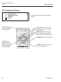
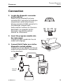
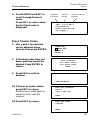
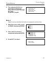
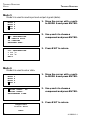
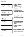
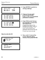
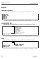
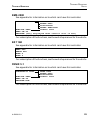
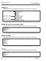
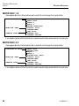
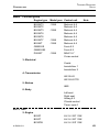
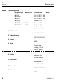
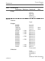
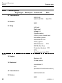
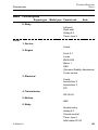
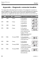
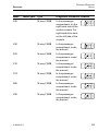
T
Trouble-Shooting - VOLVO
ROUBLE-SHOOTING
VOLVO
Foreword
The Multi-Tester pro software cassette is the component that gives the
diagnostic equipment its unique test characteristics: All data required to
make the test system operate are stored on the software cassette.
The software cassette can easily be replaced enabling the Multi-Tester pro
to be rapidly adapted to the trouble-shooting job at hand.
This Trouble-Shooting instruction describes the serial application for
Trouble-Shooting via the diagnostics socket on Volvo cars.
Copyright AUTODIAGNOS
The contents of this document can be changed without notice and should not therefore
be regarded as binding on AUTODIAGNOS.
AUTODIAGNOS is not responsible for any errors which may appear in this document.
In any event, AUTODIAGNOS accepts no liability for any loss or damage arising from
the use of this document nor of the hardware or software described herein.
Neither the whole nor any part of this document may be copied, reproduced or duplicated in any material form, except for personal use, without the prior written approval
of AUTODIAGNOS. Neither may the contents be passed on to third parties or used in
any other unauthorized manner.
A 0909012-1
1
TROUBLE-SHOOTING
VOLVO
CONTENTS
Contents
Foreword .......................................................................................................... 1
Introduction ....................................................................................................... 5
Presentation of the manual ........................................................................... 5
Presentation of the serial application ............................................................ 5
Cars with SRS (airbag)/SIPS-bag ............................................................. 7
The display and keys ................................................................................ 8
Connection ....................................................................................................... 9
Trouble-Shooting ............................................................................................. 10
Start ........................................................................................................... 10
Working procedure ..................................................................................... 11
Snapshot .................................................................................................... 13
Save values ............................................................................................ 13
Transfer readings to PC .......................................................................... 13
Erase snapshots ..................................................................................... 13
Common functions, Volvo Diagnos, first and second versions .................... 14
Read DTC:s ........................................................................................... 14
Erase Trouble Codes .............................................................................. 15
Checking function 2 ................................................................................ 16
Checking function 3 ................................................................................ 16
Checking function 4 ................................................................................ 17
Checking function 5 ................................................................................ 18
Checking function 6 ................................................................................ 18
Common functions, Volvo Diagnos, third version ........................................ 19
Read Trouble Codes ............................................................................... 19
Erase Trouble Codes .............................................................................. 20
Monitor test ............................................................................................. 21
Komponentaktivering .............................................................................. 21
Read controller ID .................................................................................. 22
Service ....................................................................................................... 23
Engine ........................................................................................................ 24
CRUISE CONTROL ............................................................................... 24
DIESEL MSA 15.7 .................................................................................. 24
DSA ........................................................................................................ 24
EMS 2000 ............................................................................................... 25
EZ 116K ................................................................................................. 25
FENIX 5.1 ............................................................................................... 25
FENIX 5.2 ............................................................................................... 25
FENIX 3B up to and including 1992 ........................................................ 26
2
A 0909012-1
CONTENTS
TROUBLE-SHOOTING
VOLVO
FENIX 3B 1993– .................................................................................... 26
LH 2.4 ..................................................................................................... 26
LH 3.1 ..................................................................................................... 26
LH 3.2 /EZ 129K ..................................................................................... 27
LUCAS ................................................................................................... 27
MELCO 1 ............................................................................................... 27
MOTRONIC 1.8 ...................................................................................... 27
MOTRONIC 4.3 ...................................................................................... 28
MOTRONIC 4.4 ...................................................................................... 28
REGINA ................................................................................................. 28
REX-I ...................................................................................................... 28
TURBO CONTROL ................................................................................ 29
Electrical ..................................................................................................... 30
CEM III ................................................................................................... 30
IMMOBILIZER 2 ..................................................................................... 30
IMMOBILIZER 2, S/V/40 ........................................................................ 30
IMMOBILIZER 3 ..................................................................................... 31
COMBI VDO/YASAKI ............................................................................. 31
COMBI, S/V/40 ....................................................................................... 31
COMBI 800 up to and including 1995 ..................................................... 32
TBH IMMO ............................................................................................. 32
RTI ......................................................................................................... 32
Transmission .............................................................................................. 33
AW 30-40 / 30-43, 900 up to and including 1995 .................................... 33
AW 30-40 / 30-43, 900 1996–, S/V/90 .................................................... 33
AW 50-42 / AW 50-42T, 800 up to and including 1995 ............................ 33
AW 50-42 / AW 50-42 TDI, 800 1996–, S/V/C/70, S/V/40 ....................... 33
Brakes ........................................................................................................ 34
ABS, 400, 700, 800 up to and including 1995, 900 ................................. 34
ABS, S/V/40 ........................................................................................... 34
ABS, 800 1996–, S/V/C/70, S/V/90, S/V/40 ............................................ 34
Body ........................................................................................................... 35
ADD HEATER 912-D .............................................................................. 35
AIRBAG 2.2/2.3, 800 up to and including 1995, 900 up to and including
1995 ....................................................................................................... 35
AIRBAG, 400 .......................................................................................... 35
AIRBAG 6.2 ............................................................................................ 35
CLIMATE CONTROL, 800 ...................................................................... 35
CLIMATE CONTROL, S/V/40 ................................................................. 36
CLIMATE CONTROL, S/V/C/70 .............................................................. 36
KEYLESS ENTRY, 400 ........................................................................... 36
A 0909012-1
3
TROUBLE-SHOOTING
VOLVO
CONTENTS
TIMER TYPE 4 ....................................................................................... 36
SRS CAB ............................................................................................... 36
ROPS ..................................................................................................... 37
CCU ....................................................................................................... 37
POWER SEAT, 800 up to and including 1995, 900 up to and including
1995 ....................................................................................................... 37
LEFT SEAT, RIGHT SEAT ...................................................................... 37
LEFT SEAT, RIGHT SEAT, C70 .............................................................. 38
KEYLESS ENTRY, S/V/40 ...................................................................... 38
VGLA ...................................................................................................... 38
Faultmessages ............................................................................................... 39
Wrong cabling connected ....................................................................... 39
Communication error .............................................................................. 39
SWITCH THE IGNITION OFF AND ON ................................................. 39
Appendix – Controllers in different car models ................................................ 40
Appendix – Diagnostic connector location ...................................................... 48
Scalingabbrevations ....................................................................................... 67
4
A 0909012-1
INTRODUCTION
TROUBLE-SHOOTING
VOLVO
Introduction
Presentation of the manual
This user manual describes how the Multi-Tester pro is used for testing
Volvo. The manual contains the following sections:
Presentation of the serial application
Brief presentation of the functions, displays and keys of the program.
Connection
Brief instruction for connecting the Multi-Tester pro hand unit to a vehicle.
Trouble shooting
Step-by-step instructions for using the Multi-Tester pro hand unit together
with the application.
Fault messages
Description of fault messages during faults in communication between the
Multi-Tester pro hand unit and the vehicle.
Presentation of the serial application
The Multi-Tester pro hand unit can communicate with all electronic ECU:s
(electronic control unit) in the vehicle via a diagnostic connector.
Diagnostic Trouble Codes (DTC)
The application can read diagnostic trouble codes DTC, present these in
plain language and delete the trouble codes.
Reading the ECU version
The application can read and display the identity of the ECU.
Component activation
The application can activate components connected to the ECU.
A 0909012-1
5
TROUBLE-SHOOTING
VOLVO
INTRODUCTION
Display Data Parameters (data stream)
The application can continually read out and display measurement values
from the ECU. The measurement values can be stored in the instrument
for later use.
The application can also read out single measurement values.
Alter adaption values
The application can change programmable values in the ECU. These
values could be service interval, idle speed etc.
The application can also reset the adaption values in the ECU.
Set service interval
The application can set a new service interval, and turn off the service
indications on the instrument panel.
Code ECU
The application can re-code a ECU. There is a code for each ECU. The code
configures the ECU for different variants of vehicles, such as transmission
type and the number of cylinders.
6
A 0909012-1
INTRODUCTION
TROUBLE-SHOOTING
VOLVO
Cars with SRS (airbag)/SIPS-bag
NOTE!
Cars fitted with SRS (Supplemental Restraint System)/SIPS-bag must
be treated with extra care during repair work. This is to avoid the
following:
1. Injury occurring during repair work.
2. Damage to or malfunction of the systems for SRS/SIPS bag.
If in doubt, read the SRS and SIPS bag-service manual.
Does the car have an SRS/SIPS bag?
The easiest way to identify cars with SRS is by the letters SRS on the central
boss of the steering wheel. If the car also has an airbag on the passenger side,
the letters SRS are embossed on the dash above the glovebox. From year
models 1993, SRS cars also have pyrotechnic belt tensioners in the B-posts.
A SIPS bag is only fitted to SRS cars from 1995 onwards. There is a SIPS
bag decal on the windscreen and on the seat bay.
Instrument panel or around the steering column cover
Take care that SRS wires do not get trapped, chafed or punctured by screws
when working on sound insulation bulkhead, knee protection, ignition lock,
steering column covers, glovebox, instrument panel, sills and B-post.
Tunnel console
The SRS collision sensor is located between the handbrake and the gear lever,
in the central console. Never mount accessories near the sensor. On the 1992
year model, the collision sensor connected must never be unplugged.
Work on steering and front suspension
When working with the steering wheel, steering column or steering gear,
certain operations must be carried out using methods in the SRS service
manual. Read the relevant sections! If the steering wheel is turned more
than three turns in either direction, the contact roller will be damaged.
Seats
The SIPS bag sensor unit is located in the front part of the seat bay. The
SIPS can be triggered by impacts or by pressure against the seat bay when
the door is closed. Before doing any work involving a seat, see the service
manual about SIPS bag.
A 0909012-1
7
TROUBLE-SHOOTING
VOLVO
INTRODUCTION
The display and keys
3.
4.
5.
8.
é
ELECTRICAL
TRANSMISSION
BRAKES
BODY
Press F3 to see a snapshot of the information
for transfer to PC
F1
F2
YES
List of menu choices, the selected alternative is
marked.
F3
Use é and ê to move the cursor
between menu choices, or to update
groups of figures.
NO
Use ç and è to move the cursor
between numbers when updating
figures, or to move through long texts.
Use ENTER to activate your selection.
HELP
Use HELP to get
diagnostic help, i.e. a
description of the faults
which the Multi-Tester
pro has discovered.
8
EXIT
ENTER
Use EXIT to leave a function and return to the previous menu.
A 0909012-1
TROUBLE-SHOOTING
VOLVO
CONNECTION
Connection
1. Locate the diagnostic connector
on the vehicle
Some cars are fitted with a 6-way
connector (DLC connector) in the engine
compartment, whilst others have a
16-way connector (CARB connector) in
the passenger compartment.
Some common locations for these are
described in an appendix to this
document. See also the vehicle
manual for information.
2. Insert the program cassette into
the instrument
Choose the right cassette for the cat
model and language.
3. Connect Multi-Tester pro via the
diagnostics socket adapter
Choose the correct adapter for the car
model and type of socket. See appendix
to this document.
16-way CARB
connector
F1
F2
6-way DLC
connector
A 0909012-1
F3
NO
YES
HELP
EXIT
ENTER
9
TROUBLE-SHOOTING
VOLVO
TROUBLE-SHOOTING
Trouble-Shooting
Start
The program is re-started each time the power supply is interrupted
and re-connected.
The Multi-Tester pro executes a self-diagnosis routine when it boots up,
then displays the current versions of hardware and software in use.
NOTE!
The ignition must be switched on to allow the instrument to contact
the ECU. Some ECU:s power down after a while when the engine is
not running.
NOTE!
If the instrument is used when driving, an assistant must operate
the instrument.
10
A 0909012-1
TROUBLE-SHOOTING
VOLVO
TROUBLE-SHOOTING
Working procedure
1. Choose language
Each cassette contains two
languages.
Use é and ê to move the cursor
between menu choices, then
press ENTER.
2. Choose car model
Depending on the cabling
connected, different menu
options appear.
Connected to 16-way CARB
connector: 800, 900, S/V/70,
S/V/90, C70.
Connected to 6-way connector
via adapter: 200, 400, 700, 800,
900.
Use é and ê to move the cursor
between menu choices, then
press ENTER.
3. Choose function group
Depending on the chosen car
model, Multi-Tester pro shows a
list of function groups.
Use é and ê to move the cursor
between menu choices, then
press ENTER.
A 0909012-1
SVENSKA
SUOMI
SNAPSHOTS
200 SERIES
400 SERIES
700 SERIES
1.
2.
3.
4.
SERVICE
ENGINE
ELECTRICAL
TRANSMISSION
↓
↓
11
TROUBLE-SHOOTING
VOLVO
LH 3.2 DI EZ 129K
FENIX 5.2
MOTRONIC 4.3
↓
MOTRONIC 4.4
TROUBLE-SHOOTING
4. Choose controller
Depending on the chosen car
model, Multi-Tester pro shows a
list of controllers.
Use é and ê to move the cursor
between menu choices, then
press ENTER.
The function groups are
described in separate sections
below.
5. Choose test
Depending on the chosen car
model, Multi-Tester pro shows a
list of tests and actions.
Use é and ê to move the cursor
between menu choices, then
press ENTER.
In some cases, Multi-Tester pro
states that an action must be
performed, eg “Start engine” or
“Wait”. Perform the action and
press ENTER.
12
A 0909012-1
TROUBLE-SHOOTING
TROUBLE-SHOOTING
VOLVO
Snapshot
Snapshot works in all menus when
a controller has been chosen.
Save values
Press F3 to save readings in
Multi-Tester pro.
Transfer readings to PC
1. Connect Multi-Tester pro to
a PC
See the manual for the PC
program for more information.
2. Use é and ê to move the
cursor between menu
choices, then press ENTER.
3. Transfer the information
See the manual for the PC
program for more information.
DOWNL. SNAPSHOTS
ERASE SNAPSHOTS
SNAPSHOTS: 2
é/ê/ENTER/EXIT
PC communication
mode
EXIT
Erase snapshots
1. Use é and ê to move the
cursor between menu
choices, then press ENTER.
DOWNL. SNAPSHOTS
ERASE SNAPSHOTS
SNAPSHOTS: 2
é/ê/ENTER/EXIT
2. Confirm by pressing ENTER
DU YOU WANT
TO ERASE ALL
SNAPSHOTS?
YES/NO
A 0909012-1
13
TROUBLE-SHOOTING
VOLVO
TROUBLE-SHOOTING
Common functions, Volvo Diagnos, first and second
versions
2.
3.
4.
5.
ENGINE
ELECTRICAL
TRANSMISSION
BRAKES
AW 50-42
CONNECT ADAPTER
TO DIAG CONN A,
THEN TURN IGN ON
ENTER/EXIT
Read DTC:s
READ DTC
ERASE DTC
MODE 2
MODE 3
Number of
DTCs:1
1. Move the cursor with é and
ê to the correct function
group and press ENTER.
2. Move the cursor with é and
ê to the correct system and
press ENTER.
3. The instrument tells you
which diagnostics socket to
use. Connect the instrument
and press ENTER
1. Use é and ê to move the
cursor between menu
choices, then press ENTER.
2. Press ENTER to see the fault
description.
ENTER/EXIT
14
A 0909012-1
TROUBLE-SHOOTING
VOLVO
TROUBLE-SHOOTING
3. Press ENTER and EXIT to
scroll through the fault
codes.
Press EXIT to return when
the first fault code is
displayed.
Diagnostics
socket used
Code from
controller
Fault in the order as
presented
(A1) 1-1-2 NR:1
Solenoid S1
short-circuited
to supply
Erase Trouble Codes
1. Use é and ê to move the
cursor between menu
choices, then press ENTER.
2. If the fault codes have not
been read they cannot be
deleted. Press ENTER to
return.
3. Press YES to confirm
deletion.
READ DTC
ERASE DTC
MODE 2
MODE 3
Not allowed
all DTCs have
not been read
EXIT
ERASE DTC?
YES/NO/EXIT
4.1 If the error codes remain,
press EXIT to return.
Read the error codes again to
see which error code still
remains.
4.2 Press EXIT to return.
DTC not erased!
Fault
still exists
EXIT
DTC has been
erased
EXIT
A 0909012-1
15
TROUBLE-SHOOTING
VOLVO
TROUBLE-SHOOTING
Mode 2
Mode 2 involves confirmation of the activation of components and
functions (input signals to controller).
READ DTC
ERASE DTC
MODE 2
MODE 3
1. Move the cursor with é and ê
to MODE 2 and press ENTER.
2. Activate the sensor and
press ENTER
ACTIVATE SENSOR
(A1) 2-4-2
Gear selector
in position P
OK
(A1)
x-x-x
3. The function is confirmed.
Press ENTER
4. If there is an error,
“INVALID CODE” appears.
Press ENTER
Invalid code
Mode 3
Mode 3 involves cyclic activation of components and functions.
READ DTC
ERASE DTC
MODE 2
MODE 3
16
1. Move the cursor with é and ê
to MODE 3 and press ENTER.
A 0909012-1
TROUBLE-SHOOTING
VOLVO
TROUBLE-SHOOTING
2. The components that are
activated are displayed.
Use é and ê to scroll through
the lines.
Press EXIT to quit.
Solenoid S1
operating
Solenoid S2
operating
Mode 4
Mode 4 involves individual activation of components and functions.
1. Move the cursor with é and ê
to MODE 4 and press ENTER.
2. Use é and ê to choose a
component and press ENTER.
MODE
MODE
MODE
MODE
3
4
5
6
SOLENOID
SOLENOID
SOLENOID
SOLENOID
S1
S1
SL
STH
3. Press EXIT to return.
Function
activated
A 0909012-1
17
TROUBLE-SHOOTING
VOLVO
TROUBLE-SHOOTING
Mode 5
Mode 5 is used to read input and output signals (data).
MODE
MODE
MODE
MODE
1. Move the cursor with é and ê
to MODE 5 and press ENTER.
3
4
5
6
OIL TEMPERATURE
TP SENSOR STAT.
TP OPENING
ENGAGEM.STAT.
2. Use é and ê to choose a
component and press ENTER.
3. Press EXIT to return.
OIL TEMPERATURE
= 29 °C
= 84 °F
EXIT
Mode 6
Mode 6 is used to enter data.
MODE
MODE
MODE
MODE
1. Move the cursor with é and ê
to MODE 6 and press ENTER.
3
4
5
6
*RESET ADAPT. TP
*RESET ADAPT.
ENGAGEMENT TIME
2. Use é and ê to choose a
component and press ENTER.
3. Press EXIT to return.
Requested
action done
EXIT
18
A 0909012-1
TROUBLE-SHOOTING
VOLVO
TROUBLE-SHOOTING
Common functions, Volvo Diagnos, third version
Read Trouble Codes
1. Use é and ê to move the
cursor between menu
choices, then press ENTER.
READ DTCs
ERASE DTCs
ACTIVATION
2. Press ENTER to reach the
fault code menu.
NUMBER OF DTCs
2
ENTER/EXIT
Fault in the order as
presented
Volvo diagnosis code
3. Press ENTER to see the next
fault code.
Press ê to see a status
message.
4. Press ê to see counters.
Press é to return to fault
code.
AT 121
NR:01
SHIFT SOLENOID
S1
ê/ENTER/EXIT
SHORT-CIRCUIT
TO GROUND
PO750
é/ê
OBDII-code
5. Press ê to see freeze frame.
Press é to return to status.
COUNTER 1=
8
é/ê
A 0909012-1
19
TROUBLE-SHOOTING
VOLVO
THROTT POS
OILTEMP
SPEED
ENG RPM
TROUBLE-SHOOTING
=35%
=64°C
=51km/h
=928rpm
SHIFT MODE 1
=N
GEL SIG A
=HIGH
GEL SIG B
=LOW
GEL SIG C
=HIGH
Erase Trouble Codes
6. Press ê to see rolling
readings.
Press EXIT to return to
counter.
Use é/ê to see next/previous
parameter.
7. Press EXIT to return to
freeze frame. Use é/ê to see
next/previous parameter.
1. Use é and ê to move the
cursor between menu
choices, then press ENTER.
READ DTCs
ERASE DTCS
ACTIVATION
ALL DTCs
NOT READ
ENTER
ERASE DTCs ?
2. If the fault codes have not
been read they cannot be
deleted. Press ENTER to
return.
3. Press YES to confirm
deletion.
YES/NO/EXIT
DTCs
NOT ERASED
ENTER
20
4.1 If error codes remain, press
ENTER to return.
Read the error codes again to see
which error code still remains.
A 0909012-1
TROUBLE-SHOOTING
VOLVO
TROUBLE-SHOOTING
4.2 If the error codes have been
deleted, press ENTER to
return.
DTCs
ERASED
ENTER
Component activation
1. Use é and ê to move the
cursor between menu
choices, then press ENTER.
READ DTCs
ERASE DTCs
ACTIVATION
2. Move the cursor to the
correct option with é and ê,
then press YES to activate
and NO to stop activation.
SOLENOID
SOLENOID
SOLENOID
SOLENOID
3. When activation has started,
press HELP to switch to
rolling reading.
This is only possible in certain
systems.
S1
S2
SL
STH
SHIFT MODE 1
=N
GEL SIG A
=HIGH
GEL SIG B
=LOW
GEL SIG C
=HIGH
4. Press EXIT to return.
Monitor test
1. Use é and ê to move the
cursor between menu
choices, then press ENTER.
2. Move the cursor with é and
ê to the correct sub-function
and press ENTER.
A 0909012-1
DIAGNOSTIC TEST
MONITOR TEST
READ CM ID
SCROLL LIST
21
TROUBLE-SHOOTING
VOLVO
SHIFT MODE 1
=N
GEL SIG A
=HIGH
GEL SIG B
=LOW
GEL SIG C
=HIGH
001
002
003
004
SHIFT MOD=P
GEL SIG=LOW
GEL SIG=LOW
GEL SIG=LOW
001
002
003
004
SHIFT MOD=P
GEL SIG=LOW
GEL SIG=LOW
GEL SIG=LOW
TROUBLE-SHOOTING
3. Press ENTER to switch to
rolling readings.
4. Press é/ê to see next/
previous parameter.
Press ç and è to show/hide
parameter numbers.
5. Press YES to lock the top
line and NO to unlock the
last locked line.
A locked line stays in the
window when other lines are
scrolled up and down. The
cursor at the equals sign
indicates that a line is locked.
Three lines can be locked.
Read controller ID
DIAGNOSTIC TEST
MONITOR TEST
READ CM ID
1. Use é and ê to move the
cursor between menu
choices, then press ENTER.
CONTACT WITH
AW50-42
P/N XXXXXXXXX
ENTER/EXIT
22
A 0909012-1
TROUBLE-SHOOTING
VOLVO
TROUBLE-SHOOTING
Service
This menu option is only
available on cars with combi
instruments and trip computer.
CLEAR SRL
Press ENTER to reset the service
indication.
A 0909012-1
23
TROUBLE-SHOOTING
VOLVO
TROUBLE-SHOOTING
Engine
CRUISE CONTROL
See appendix for information as to which cars have this controller.
READ DTC
ERASE DTC
MODE 2
MODE 4
MODE 5
For a description of the functions, see the workshop manual for the vehicle.
DIESEL MSA 15.7
See appendix for information as to which cars have this controller.
DIAGNOSTIC TEST
MONITOR TEST
READ CM ID
READ DTCs
ERASE DTCs
ACTIVATION
PROGRAM
PUMP TEST
EGR TEST
ADJUST LOW IDLE
SCROLL LIST
For a description of the functions, see the workshop manual for the vehicle.
DSA
See appendix for information as to which cars have this controller.
DIAGNOSTIC TEST
MONITOR TEST
READ CM ID
READ DTCs
ERASE DTCsR
AKTIVATION
RESET ADAPTION
SCROLL LIST
For a description of the functions, see the workshop manual for the vehicle.
24
A 0909012-1
TROUBLE-SHOOTING
VOLVO
TROUBLE-SHOOTING
EMS 2000
See appendix for information as to which cars have this controller.
DIAGNOSTIC TEST
READ DTCs
ERASE DTCs
ACTIVATION
RESET ADAPTION
SCROLL LIST
MONITOR TEST
READ CM ID
PROGRAM (Only displayed when control unit is new)
For a description of the functions, see the workshop manual for the vehicle.
EZ 116K
See appendix for information as to which cars have this controller.
READ DTC
ERASE DTC
MODE 2
MODE 3
For a description of the functions, see the workshop manual for the vehicle.
FENIX 5.1
See appendix for information as to which cars have this controller.
DIAGNOSTIC TEST
MONITOR TEST
READ CM ID
PROGRAM ECM
READ DTCs
ERASE DTCs
ACTIVATION
SCROLL LIST
For a description of the functions, see the workshop manual for the vehicle.
A 0909012-1
25
TROUBLE-SHOOTING
VOLVO
TROUBLE-SHOOTING
FENIX 5.2
See appendix for information as to which cars have this controller.
DIAGNOSTIC TEST
MONITOR TEST
FREEZE TEST
READ DTCs
ERASE DTCs
MODE 2
MODE 3
MODE 4
SCROLL LIST
PREDEFINED
OWN LIST
FREEZE DTC
FREEZE VALUES
For a description of the functions, see the workshop manual for the vehicle.
FENIX 3B up to and including 1992
See appendix for information as to which cars have this controller.
READ DTC
ERASE DTC
MODE 2
MODE 3
For a description of the functions, see the workshop manual for the vehicle.
FENIX 3B 1993–
See appendix for information as to which cars have this controller.
READ DTC
ERASE DTC
MODE 2
MODE 3
MODE 4
MODE 5
For a description of the functions, see the workshop manual for the vehicle.
LH 2.4
See appendix for information as to which cars have this controller.
READ DTC
ERASE DTC
MODE 2
MODE 3
For a description of the functions, see the workshop manual for the vehicle.
26
A 0909012-1
TROUBLE-SHOOTING
VOLVO
TROUBLE-SHOOTING
LH 3.1
See appendix for information as to which cars have this controller.
READ DTC
ERASE DTC
MODE 2
MODE 3
For a description of the functions, see the workshop manual for the vehicle.
LH 3.2 /EZ 129K
See appendix for information as to which cars have this controller.
DIAGNOSTIC TEST
MONITOR TEST
FREEZE TEST
READ DTCs
READ DTCs
MODE 2
MODE 3
SCROLL LIST
PREDEFINED
OWN LIST
FREEZE DTC
FREEZE VALUES
For a description of the functions, see the workshop manual for the vehicle.
LUCAS
See appendix for information as to which cars have this controller.
DIAGNOSTIC TEST
MONITOR TEST
READ CM ID
READ DTCs
READ DTCs
ACTIVATION
SCROLL LIST
For a description of the functions, see the workshop manual for the vehicle.
MELCO 1
See appendix for information as to which cars have this controller.
DIAGNOSTIC TEST
MONITOR TEST
READ CM ID
READ DTCs
READ DTCs
ACTIVATION
SCROLL LIST
For a description of the functions, see the workshop manual for the vehicle.
A 0909012-1
27
TROUBLE-SHOOTING
VOLVO
TROUBLE-SHOOTING
MOTRONIC 1.8
See appendix for information as to which cars have this controller.
DIAGNOSTIC TEST
MONITOR TEST
FREEZE TEST
READ DTCs
READ DTCs
MODE 2
MODE 3
RESET ADAPTION
SCROLL LIST
PREDEFINED
OWN LIST
FREEZE DTC
FREEZE VALUES
For a description of the functions, see the workshop manual for the vehicle.
MOTRONIC 4.3
See appendix for information as to which cars have this controller.
DIAGNOSTIC TEST
MONITOR TEST
FREEZE TEST
READ DTCs
ERASE DTCs
MODE 2
MODE 3
DIAGNOSTIC TEST
SCROLL LIST
PREDEFINED
OWN LIST
FREEZE DTC
FREEZE VALUES
For a description of the functions, see the workshop manual for the vehicle.
28
A 0909012-1
TROUBLE-SHOOTING
VOLVO
TROUBLE-SHOOTING
MOTRONIC 4.4
See appendix for information as to which cars have this controller.
DIAGNOSTIC TEST
READ DTCs
ERASE DTCs
ACTIVATION
RESET ADAPTION
MONITOR TEST
READ CM ID
ACTIVATE COMP.
ACTIVATE DIAG.
SAS DIAGNOSIS
LEAKAGEDIAGNOSIS
EVAP DIAGNOSIS
RESET ALL
RESET FLYWHEEL
RESET ALL EX F.W
DIAGNOSTIC TEST
SCROLL LIST
For a description of the functions, see the workshop manual for the vehicle.
REGINA
See appendix for information as to which cars have this controller.
READ DTC
ERASE DTC
MODE 2
MODE 3
REX-I
See appendix for information as to which cars have this controller.
READ DTC
READ DTC
MODE 2
For a description of the functions, see the workshop manual for the vehicle.
TURBO CONTROL
See appendix for information as to which cars have this controller.
READ DTC
ERASE DTC
MODE 3
For a description of the functions, see the workshop manual for the vehicle.
A 0909012-1
29
TROUBLE-SHOOTING
VOLVO
TROUBLE-SHOOTING
Electrical
CEM III
See appendix for information as to which cars have this controller.
READ DTC
ERASE DTC
MODE 2
MODE 3
MODE 4
For a description of the functions, see the workshop manual for the vehicle.
IMMOBILIZER 2
See appendix for information as to which cars have this controller.
DIAGNOSTIC TEST
MONITOR TEST
READ CM ID
PROGRAM IMMO
READ DTCs
ERASE DTCs
SCROLL LIST
ADD KEY
ERASE/NEW KEYS
BLANK VERL. CODE
PROGRAM NEW IMMO
For a description of the functions, see the workshop manual for the vehicle.
IMMOBILIZER 2, S/V/40
See appendix for information as to which cars have this controller.
DIAGNOSTIC TEST
MONITOR TEST
READ CM ID
PROGRAM IMMO
READ DTCs
ERASE DTCs
ACTIVATION
SCROLL LIST
ADD KEY
ERASE/NEW KEYS
BLANK VIN-CODE
PROGRAM NEW IMMO
For a description of the functions, see the workshop manual for the vehicle.
30
A 0909012-1
TROUBLE-SHOOTING
VOLVO
TROUBLE-SHOOTING
IMMOBILIZER 3
See appendix for information as to which cars have this controller.
DIAGNOSTIC TEST
MONITOR TEST
READ CM ID
PROGRAM IMMO
READ DTCs
ERASE DTCs
ACTIVATION
SCROLL LIST
ADD KEY
ERASE/NEW KEYS
BLANK VIN-KOD/BLANK VERL. CODE
PROGRAM NEW IMMO
For a description of the functions, see the workshop manual for the vehicle.
COMBI VDO/YASAKI
See appendix for information as to which cars have this controller.
DIAGNOSTIC TEST
READ DTCs
ERASE DTCs
ACTIVATION
MONITOR TEST
READ CM ID
CLEAR SRL
PROGRAM COMBI
SCROLL LIST
READ COMBI
PROGRAM COMBI
PROG. TRIP COMP.
FUEL IND. UPDATE
For a description of the functions, see the workshop manual for the vehicle.
COMBI, S/V/40
See appendix for information as to which cars have this controller.
DIAGNOSTIC TEST
MONITOR TEST
READ CM ID
PROGRAM COMBI
CLEAR SRL
READ DTCs
ERASE DTCs
ACTIVATION
CM TEST
SCROLL LIST
For a description of the functions, see the workshop manual for the vehicle.
A 0909012-1
31
TROUBLE-SHOOTING
VOLVO
TROUBLE-SHOOTING
COMBI 800 up to and including 1995
See appendix for information as to which cars have this controller.
READ DTC
ERASE DTC
MODE 3
MODE 4
MODE 5
MODE 6
For a description of the functions, see the workshop manual for the vehicle.
TBH IMMO
See appendix for information as to which cars have this controller.
READ DTC
ERASE DTC
For a description of the functions, see the workshop manual for the vehicle.
RTI
See appendix for information as to which cars have this controller.
DIAGNOSTIC TEST
MONITOR TEST
READ CM ID
READ DTCs
ERASE DTCs
ACTIVATION
SYSTEM TEST
SCROLL LIST
For a description of the functions, see the workshop manual for the vehicle.
32
A 0909012-1
TROUBLE-SHOOTING
VOLVO
TROUBLE-SHOOTING
Transmission
AW 30-40 / 30-43, 900 up to and including 1995
See appendix for information as to which cars have this controller.
READ DTC
ERASE DTC
MODE 2
MODE 3
MODE 4
MODE 5
MODE 6
For a description of the functions, see the workshop manual for the vehicle.
AW 30-40 / 30-43, 900 1996–, S/V/90
See appendix for information as to which cars have this controller.
DIAGNOSTIC TEST
MONITOR TEST
READ CM ID
READ DTCs
ERASE DTCs
ACTIVATION
SCROLL LIST
For a description of the functions, see the workshop manual for the vehicle.
AW 50-42 / AW 50-42T, 800 up to and including 1995
See appendix for information as to which cars have this controller.
READ DTC
ERASE DTC
MODE 2
MODE 3
MODE 4
MODE 5
MODE 6
For a description of the functions, see the workshop manual for the vehicle.
A 0909012-1
33
TROUBLE-SHOOTING
VOLVO
TROUBLE-SHOOTING
AW 50-42 / AW 50-42 TDI, 800 1996–, S/V/C/70, S/V/40
See appendix for information as to which cars have this controller.
DIAGNOSTIC TEST
MONITOR TEST
READ CM ID
READ DTC
ERASE DTC
ACTIVATION
SCROLL LIST
For a description of the functions, see the workshop manual for the vehicle.
34
A 0909012-1
TROUBLE-SHOOTING
VOLVO
TROUBLE-SHOOTING
Brakes
ABS, 400, 700, 800 up to and including 1995, 900
See appendix for information as to which cars have this controller.
READ DTC
ERASE DTC
MODE 4
For a description of the functions, see the workshop manual for the vehicle.
ABS, S/V/40
See appendix for information as to which cars have this controller.
DIAGNOSTIC TEST
MONITOR TEST
READ CM ID
READ DTCs
ERASE DTCs
ACTIVATION
SCROLL LIST
For a description of the functions, see the workshop manual for the vehicle.
ABS, 800 1996–, S/V/C/70, S/V/90, S/V/40
See appendix for information as to which cars have this controller.
DIAGNOSTIC TEST
MONITOR TEST
READ CM ID
READ DTCs
ERASE DTCs
ACTIVATION
SCROLL LIST
For a description of the functions, see the workshop manual for the vehicle.
A 0909012-1
35
TROUBLE-SHOOTING
VOLVO
TROUBLE-SHOOTING
Body
ADD HEATER 912-D
See appendix for information as to which cars have this controller.
DIAGNOSTIC TEST
MONITOR TEST
READ CM ID
PROGRAM
READ DTCs
ERASE DTCs
ACTIVATION
VOLTAGE PROT.
SCROLL LIST
For a description of the functions, see the workshop manual for the vehicle.
AIRBAG 2.2/2.3, 800 up to and including 1995, 900 up to and
including 1995
See appendix for information as to which cars have this controller.
READ DTC
ERASE DTC
MODE 4
For a description of the functions, see the workshop manual for the vehicle.
AIRBAG, 400
See appendix for information as to which cars have this controller.
READ DTC
ERASE DTC
MODE 4
For a description of the functions, see the workshop manual for the vehicle.
AIRBAG 6.2
See appendix for information as to which cars have this controller.
DIAGNOSTIC TEST
MONITOR TEST
READ CM ID
READ DTCs
ERASE DTCs
SCROLL LIST
For a description of the functions, see the workshop manual for the vehicle.
36
A 0909012-1
TROUBLE-SHOOTING
VOLVO
TROUBLE-SHOOTING
CLIMATE CONTROL, 800
See appendix for information as to which cars have this controller.
READ DTC
ERASE DTC
MODE 2
MODE 4
For a description of the functions, see the workshop manual for the vehicle.
CLIMATE CONTROL, S/V/40
See appendix for information as to which cars have this controller.
DIAGNOSTIC TEST
MONITOR TEST
READ CM ID
PROGRAM
ADJUST MOTORS
READ DTCs
ERASE DTCs
SCROLL LIST
For a description of the functions, see the workshop manual for the vehicle.
CLIMATE CONTROL, S/V/C/70
See appendix for information as to which cars have this controller.
DIAGNOSTIC TEST
MONITOR TEST
READ CM ID
PROGRAM
ADJUST MOTORS
READ DTCs
ERASE DTCs
SCROLL LIST
For a description of the functions, see the workshop manual for the vehicle.
KEYLESS ENTRY, 400
See appendix for information as to which cars have this controller.
READ DTC
ERASE DTC
MODE 2
MODE 4
MODE 5
MODE 6
For a description of the functions, see the workshop manual for the vehicle.
A 0909012-1
37
TROUBLE-SHOOTING
VOLVO
TROUBLE-SHOOTING
TIMER TYPE 4
See appendix for information as to which cars have this controller.
READ DTC
ERASE DTC
For a description of the functions, see the workshop manual for the vehicle.
SRS CAB
See appendix for information as to which cars have this controller.
DIAGNOSTIC TEST
MONITOR TEST
READ CM ID
READ DTCs
ERASE DTCs
ACTIVATION
SCROLL LIST
For a description of the functions, see the workshop manual for the vehicle.
ROPS
See appendix for information as to which cars have this controller.
DIAGNOSTIC TEST
MONITOR TEST
READ CM ID
READ DTCs
ERASE DTCs
ACTIVATION
SCROLL LIST
For a description of the functions, see the workshop manual for the vehicle.
CCU
See appendix for information as to which cars have this controller.
DIAGNOSTIC TEST
MONITOR TEST
READ CM ID
PROGRAM
READ CM ID
READ DTCs
ERASE DTCs
ACTIVATION
SCROLL LIST
For a description of the functions, see the workshop manual for the vehicle.
38
A 0909012-1
TROUBLE-SHOOTING
VOLVO
TROUBLE-SHOOTING
POWER SEAT, 800 up to and including 1995, 900 up to and
including 1995
See appendix for information as to which cars have this controller.
READ DTC
ERASE DTC
MODE 4
For a description of the functions, see the workshop manual for the vehicle.
LEFT SEAT, RIGHT SEAT
See appendix for information as to which cars have this controller.
DIAGNOSTIC TEST
MONITOR TEST
READ CM ID
READ DTCs
ERASE DTCs
ACTIVATION
SCROLL LIST
For a description of the functions, see the workshop manual for the vehicle.
LEFT SEAT, RIGHT SEAT, C70
See appendix for information as to which cars have this controller.
DIAGNOSTIC TEST
MONITOR TEST
READ CM ID
SEAT CALIBRATION
ENTRY POSITION
READ DTCs
ERASE DTCs
ACTIVATION
SCROLL LIST
For a description of the functions, see the workshop manual for the vehicle.
A 0909012-1
39
TROUBLE-SHOOTING
VOLVO
TROUBLE-SHOOTING
KEYLESS ENTRY, S/V/40
See appendix for information as to which cars have this controller.
DIAGNOSTIC TEST
MONITOR TEST
READ CM ID
PROGRAM
READ DTCs
ACTIVATION TOG.
ERASE DTCs
ACTIVATION
SENS./SIREN TEST
SCROLL LIST
PROGRAM ECU
PROGRAM KEYS
For a description of the functions, see the workshop manual for the vehicle.
VGLA
See appendix for information as to which cars have this controller.
DIAGNOSTIC TEST
MONITOR TEST
READ CM ID
PROGRAM
READ DTCs
ERASE DTcs
ACTIVATION
READ ALARM CAUSE
SCROLL LIST
READ PROG. STAT
PROGRAM MODULE
PROGRAM KEYS
For a description of the functions, see the workshop manual for the vehicle.
40
A 0909012-1
TROUBLE-SHOOTING
VOLVO
FAULTMESSAGES
Faultmessages
Wrong cabling connected
Press HELP for more
information.
Please use a
Volvo Interface
and Serial Cable
ENTER/HELP
Press ENTER to continue.
If a Volvo
Interface is
connected, send
the Inteface
for repair or
continue
é/ê/ENTER/EXIT
Communication error
Check that the cabling is
correctly connected and that the
ignition is on.
INITIALIZING
FAILURE !
ENTER/EXIT
Switch the ignition off and on
It is important to switch off the
ignition within three seconds of
the text being displayed and
that it remains switched off for
three seconds.
A 0909012-1
TURN IGNITION
OFF FOR 3 SEC.
THEN ON AGAIN
41
TROUBLE-SHOOTING
VOLVO
CONTROL UNIT
Appendix – Controllers in different car models
This appendix briefly describes the type of controller in different car models.
The list is an excerpt and is therefore incomplete. For detailed information
about the relevant car model and information about car models not listed, see
the relevant service manual.
Model
Function group
Engine type
Model year Control unit
Note
200
2: Engine
B200F
B230F
B230F US
B230FD
B230FX
1989198919901993
1992-
LH 2.4 / EZ 116K
LH 2.4 / EZ 116K
LH 3.1 / EZ 116K
LH 2.4 / EZ 116K
LH 2.4 / EZ 116K
3: El
Immobilizer 1
400
2: Engine
B16F
B18EP
B18FP
B18U
B20F
B20U
199019901990199219931993-
Fenix 3.B -92
Fenix 3.B -92
Fenix 3.B -92
Fenix 3.B -92
Fenix 3.B 93Fenix 3.B 93Cruise control
3: Electrical
CEM III
(Central Electronic Module)
Immobilizer 1
5: Brakes
ABS
42
A 0909012-1
TROUBLE-SHOOTING
VOLVO
CONTROL UNIT
Model
Function group
Engine type
Model year Control unit
Note
8: Body
Keyless entry
Airbag
Timer, type 4
700
2: Engine
B200F
B200FT
B200G
B204E
B204FT
B204GT
B230F
B230F
B230FB
B230FD
B230FT
B230G
B230GT
B234F
B234G
19891989199219891991199019891989- US
1991199319901992199019981991-
LH 2.4 / EZ 116K
LH 2.4 / EZ 116K
LH 2.4 / EZ 116K
LH 2.4 / EZ 116K
LH 2.4 / EZ 116K
LH 2.4 / EZ 116K
LH 2.4 / EZ 116K
Regina / Rex-I
LH 2.4 / EZ 116K
LH 2.4 / EZ 116K
LH 2.4 / EZ 116K
LH 2.4 / EZ 116K
LH 2.4 / EZ 116K
LH 2.4 / EZ 116K
LH 2.4 / EZ 116K
3: Electrical
Immobilizer 1
5: Brakes
ABS
8: Body
Timer, type 4
800 -> 1995
2: Engine
B5204S
B5254S
A 0909012-1
19921992-
LH 3.2 / EZ 129K
LH 3.2 / EZ 129K
43
TROUBLE-SHOOTING
VOLVO
Model
CONTROL UNIT
Function group
Engine type
B5252S
B5234T
B5202S
B5252S
D5252T
Model year Control unit
19931994-
-1998
Note
Fenix 5.2
Motronic 4.3
Fenix 5.2
Fenix 5.2
MSA 15.7
Cruise control
3: Electrical
Combi
Immobilizer 1
4: Transmission
AW 50-42
5: Brakes
ABS
8: Body
Power seat
Airbag 2.2/2.3
Climate control
Timer, type 4
800 1996->
1: Service
Combi
2: Engine
B5204S
B5254S
B5252S
B5234T
B5202S
B5252S
B5234S
B5254S
B5204T2
44
1992199219931994-
-1998
-1998
LH 3.2 / EZ 129K
LH 3.2 / EZ 129K
Fenix 5.2
Motronic 4.3
Fenix 5.2
Fenix 5.2
Motronic 4.4
Motronic 4.4
Motronic 4.4
A 0909012-1
TROUBLE-SHOOTING
VOLVO
CONTROL UNIT
Model
Function group
Engine type
B5204T3
B5234T2
B5234T3
B5234T4
B5234T6
B5234T7
B5254T
GB5252S
GB5252S2
D5252T
Model year Control unit
-1998
-1998
-1998
-1998
-1998
Note
Motronic 4.4
Motronic 4.4
Motronic 4.4
Motronic 4.4
Motronic 4.4
Motronic 4.4
Motronic 4.4
Fenix 5.2
Fenix 5.2
MSA 15.7
Cruise control
3: Electrical
Combi
Immobilizer 1
Immobilizer 2
4: Transmission
AW 50-42
AW 50-42 TDI
5: Brakes
ABS
8: Body
Left seat
Right seat
Airbag 6.2
Climate control
Timer, type 4
900 -> 1995
2: Engine
B200F
B200T
B230FB
A 0909012-1
LH 2.4 / EZ 116K
LH 2.4 / EZ 116K
LH 2.4 / EZ 116K
45
TROUBLE-SHOOTING
VOLVO
Model
CONTROL UNIT
Function group
Engine type
B234F
B230FK
B230FT
B6254F
B6304F
B6304G
Model year Control unit
19911992-
Note
LH 2.4 / EZ 116K
LH 2.4 / EZ 116K
LH 2.4 / EZ 116K
Motronic 1.8
Motronic 1.8
Motronic 1.8
Turbo control
Cruise control
3: Electrical
Immobilizer 1
4: Transmission
AW 30-40/30-43
5: Brakes
ABS
8: Body
Power seat
Airbag 2.2/2.3
Timer, type 4
900 1996->
2: Engine
Motronic 4.4
Cruise control
3: Electrical
Immobilizer 1
Immobilizer 2
4: Transmission
AW 30-40/30-43
5: Brakes
ABS
46
A 0909012-1
TROUBLE-SHOOTING
VOLVO
CONTROL UNIT
Model
Function group
Engine type
Model year Control unit
Note
8: Body
Left seat
Right seat
Airbag 6.2
Timer, type 4
S/V/C70
1: Service
Combi
2: Engine
B5202S
B5252S
GB5252S
GB5252S2
B5234S
B5254S
B5254T
B5204T2
B5204T3
B5234T2
B5234T3
B5234T4
B5234T3
B5234T6
B5234T7
D5252T
-> 1998
-> 1998
-> 1998
-> 1998
-> 1998
-> 1998
-> 1999
Fenix 5.2
Fenix 5.2
Fenix 5.2
Fenix 5.2
Motronic 4.4
Motronic 4.4
Motronic 4.4
Motronic 4.4
Motronic 4.4
Motronic 4.4
Motronic 4.4
Motronic 4.4
Motronic 4.4
Motronic 4.4
Motronic 4.4
MSA 15.7
Cruise control
Bifuel
Bifuel
3: Electrical
Combi
Immobilizer 2
Immobilizer 3
RTI
(Road and Traffic Information)
A 0909012-1
47
TROUBLE-SHOOTING
VOLVO
Model
Function group
Engine type
CONTROL UNIT
Model year Control unit
Note
4: Transmission
AW 50-42
AW 50-42 TDI
Not C70
5: Brakes
ABS
8: Body
Left seat
Right seat
Airbag 6.2
Climate control
VGLA (Volvo Guard Lock
and Alarm system
Add heater 912-D
Timer, type 4
SRS Cabriolet
C70
ROPS (Roll Over
Protection System) C70
CCU
(Cab Control Unit) C70
S/V90
2: Engine
Motronic 4.4
Cruise control
3: Electrical
Immobilizer 2
RTI
(Road and Throttle Information)
4: Transmission
AW 30-40/30-43
5: Brakes
ABS
48
A 0909012-1
TROUBLE-SHOOTING
VOLVO
CONTROL UNIT
Model
Function group
Engine type
Model year Control unit
Note
8: Body
Left seat
Right seat
Airbag 6.2
Timer, type 4
S/V40
1: Service
Combi
2: Engine
Fenix 5.1
Lucas
EMS 2000
Melco 1
DSA
(Dynamic Stability Assistance)
Cruise control
3: Electrical
Combi
Immobilizer 2
Immobilizer 3
RTI
4: Transmission
AW 50-42
5: Brakes
ABS
8: Body
Keyless entry
Airbag 6.2
Climate controll
Timer, type 4
Add heater 912-D
A 0909012-1
49
TROUBLE-SHOOTING
VOLVO
APPENDIX
Appendix – Diagnostic connector location
This appendix briefly describes the location of the diagnostic connector in
various models of cars. The list is an extract, and is therefore not complete.
Please refer to the appropriate service manual for detailed information
about each car model and information about cars which are not on this list.
Make
Model year Type
Diagnostic connector location
200
-1995
6-way
In the engine
compartment
400
-1995
6-way
In the engine
compartment
700
-1995
6-way
In the engine
compartment
800
-1995
6-way
In the engine
compartment (on
some markets there
is also a 16-way
CARB connector which
must not be used)
800
1996-
16-way CARB
In the passenger
compartment, in front
of the gear lever
900
-1995
6-way
In the engine
compartment
940
1996-
16-way CARB
In the passenger
compartment, central
console tunnel pocket
960
1996-
16-way CARB
In the passenger
compartment, in the
central console near
the handbrake
50
A 0909012-1
TROUBLE-SHOOTING
VOLVO
APPENDIX
Make
Model year Type
Diagnostic connector location
S40
16-way CARB
In the passenger
compartment, on the
right-hand side of the
central console. For
right-hand-drive cars,
on the left side of the
console.
V40
16-way CARB
In the passenger
compartment, under
the armrest
S70
16-way CARB
In the passenger
compartment, under
the armrest
V70
16-way CARB
In the passenger
compartment, under
the armrest
C70
16-way CARB
In the passenger
compartment, under
the armrest
S90
16-way CARB
In the passenger
compartment, under
the armrest
V90
16-way CARB
In the passenger
compartment, under
the armrest
A 0909012-1
51
TROUBLE-SHOOTING
VOLVO
APPENDIX – MONITOR LIST ABBREVATIONS
Appendix – Monitor List Abbrevations
12 PULSE
15 SUPPLY
48 PULSE
A/C APPROVED
A/C COMPR
A/C P SENS
A/C PR
A/C PRESS
A/C RELAY
A/C REQ.
A/C REQUEST
A/C STANDBY
A/C SWITCH
ABS LAMP
ABV DUTY
ABV STATUS
AC
AC SET
ACC LF
ACC LR
ACC POS
ACC RF
ACC RR
ACC VEH
ACCEL
ACCEL SENS
ACT SOL S1
ACT SOL S2
52
12 pulses/rev speed output signal
15 Supply
48 pulsees/rev speed output signal
A/C approved by control module
A/C compressor running status
A/C pressure sensor signal
A/C pressure, high-pressure side
A/C pressure
A/C relay signal
A/C requested by ECC or MCC
Air conditioning requested by the ECC control
module or by MCC
Engine speed change delay when air conditioning
is disengaged
A/C switch signal
ABS warning lamp, output signal
ABV duty cycle
ABV status
A/C output signal to engine control module
Air conditioning switch position
Wheel acceleration/retardation left front wheel
Wheel acceleration/retardation left rear wheel
Accelerator pedal position
Wheel acceleration/retardation right front wheel
Wheel acceleration/retardation right rear wheel
Vehicle reference acceleration/retardation
Car’s vertical accelerometer
DC signal from car’s vertical accelerometer
Activation of shift solenoid S1
Activation of shift solenoid S2
A 0909012-1
APPENDIX – MONITOR LIST ABBREVATIONS
ACT SOL SL
AFTERBLOW
AIR COND.
AIR PUMP
AIR TEMP
AIRFL.RESET
AIRFLOW
AIRPUMP RELAY
ALT. LOAD
AM AC
AM DE
AMB T SENS
AMB.TEMP
ANGLE SWITCH
BACKREST SW.
BARO
BARO SENS
BAROMETER
BATT
BATTERY
BLOWER
BRAKE
BRAKE L.SW
BRAKE LAMP
BRAKE P.SW
BRAKE PRESS
C.FAN DE
C.LOCK FUEL
C.LOCK MOT
C.LOCK SW
C.LOCK TRNK
A 0909012-1
TROUBLE-SHOOTING
VOLVO
Activation of shift solenoid SL
Afterblow, ECC runs blower fan a few minutes
after ignition off
A/C output signal
Pulsed secondary air injection system pump status
Intake air temperature
Air flow sensor reset pulse
Air flow sensor
Pulsed secondary air injection system pump relay
status
Alternator load
Air mass actual value
Air mass nominal value
Ambient temperature sensor signal
Ambient temperature sensor signal
Angle switch for the backrest in C70
Backrest switch in C70
Atmospheric pressure
Atmospheric pressure sensor signal
Atmospheric pressure
Battery voltage
Battery voltage
Blower fan output signal
Brake switch
Brake light switch
Brake light indicator output signal
Brake pedal switch
Brake force sensor
Combustion fan desired operating speed
Central lock fuel lid motor output signal
Central lock motor output signal
Central lock switch signal
Central lock trunk motor output signal
53
TROUBLE-SHOOTING
VOLVO
C.UNLOCKSW
C/R NO. 1
CAB TEMP FAN
CAB. TEMP
CAN STATUS
CAN.VALVE
CLOCK KNOB
CLUTCH P.SW
CMP SIGNAL
CO POT
CODE STORED
COMB.FAN
COMPART.FAN
CONTROL
CONV.T.MO.LH
CONV.T.MO.RH
COOL HEAT 1
COOL HEAT2/3
COOLANT PUMP
COVERLOCK
COVERLOCK.MO
CRANK SIGN
CRASH
CRU OFF?
CRUISE M
D.CYCLE
D.DOORLOCK
D.DOORULOCK
D.LOCK MOT
D+
DATE
54
APPENDIX – MONITOR LIST ABBREVATIONS
Central unlock switch signal
Immobilizer challenge response transponder
number 1
Cabin temperature sensor fan
Passenger compartment temperature
CAN bus status, transmission control module and
engine control module
EVAP canister shut off valve
Digital clock adjustment knob
Clutch pedal switch
Camshaft position sensor signal
Signal from CO potentiometer
Immobilizer transponder in key code stored status
Combustion fan actual operating speed
Passenger compartment blower fan
Control status
Convertible top motor left hand output signal
Convertible top motor right hand output signal
Relay for engine coolant heater 1
Relay for engine coolant heater 2 and 3
Coolant pump
Coverlock microswitch
Coverlock motor output signal
Cranking signal
Indicates crash status
Cruise control disengangment reason
Cruise control mode
Running (driving) cycle status
Driver door lock signal
Driver door unlock signal
Dead lock central lock motor output signal
Alternator charge voltage
Date, GPS information
A 0909012-1
APPENDIX – MONITOR LIST ABBREVATIONS
DIG.CLOCK
DIR.IND
DOOR SW
DR.AB.HI.CAP
DR.AB.LO.CAP
DR.AB.OP.CIR
DR.AB.SH.CIR
DR.AB.SH.GND
DR.AB.SH.PLS
DRIVE COMP P/N
DRVDOORSW
DSA ACTIVE
DSA FUNC
DSA SWITCH
DTEMP SHUTT
EBD PRESS
ECM ANSWER
ECM LOCKED
ECM TEMP
ECT
ECT START
ECTGAUGE
ECT-SENS
EGR
ENG FAN
ENG FAN FULL
ENG FAN HALF
ENG FAN RELAY
ENG RPM
ENGINE
ENGINE RUN
A 0909012-1
TROUBLE-SHOOTING
VOLVO
Digital clock
Direction indicator output signal
Door switch signal, except driver door
Driver airbag capacitance too high
Driver airbag capacitance too low
Driver airbag open circuit
Driver airbag short circuit
Driver airbag short circuit to ground
Driver airbag short circuit to plus
Gear selector lever output signal to driving
computer
Driver door switch signal
Anti spin control status
Dynamic Stability Assistance funtion status
Dynamic Stability Assistance switch status
Driver temperature shutter position
EBD (Electrical Brake force Distribution) pressure
switch position
Electronic control module answer to immobilizer
Electronic control module locked by immobilizer,
status
Temperatue inside control module
Engine coolant temperature
Engine coolant temperature, at start
Engine coolant temperature gauge type
Engine coolant temperature sensor
EGR controller, pulse ratio
Engine coolant fan
Engine cooling fan high speed
Engine cooling fan low speed
Engine cooling fan relay status
Engine speed RPM
Engine type
Engine status
55
TROUBLE-SHOOTING
VOLVO
ERR PRESENT
ERROR HAND
EVAP VALVE
EVAP. TEMP
EXT COUNT LF
EXT COUNT LR
EXT COUNT RF
EXT COUNT RR
F ADAP
F ADAP B
F ADAP C
F ADAP D
F ADAP E
F.C.OFF
F.CLOCK
F.L.OFF
F/PUMP RELAY
F/TRIM
F/TRIM CONT
F/TRIM IDLE
F/TRIM PART
F/TRIMPART
FACIA LED
FAN KNOB
FAN UNIT
FAULTY VIN
FR.LOCK
FR.LOCK.MO.
FR.LT.FR
FR.LT.R
FREQUENCY
FU SHUT OFF
56
APPENDIX – MONITOR LIST ABBREVATIONS
Active fault, error present
Emergency programs
Evaporator valve signal
Temperature after evaporator
Extrapolition counter left front wheel
Extrapolition counter left rear wheel
Extrapolition counter right front wheel
Extrapolition counter right rear wheel
Flywheel adaption status
Flywheel adaption, segment B
Flywheel adaption, segment C
Flywheel adaption, segment D
Flywheel adaption, segment E
Fuel consumption offset
Fault timer
Fuel level offset
Fuel pump relay
Long term fuel trim, operates quickly at idling
Long term fuel trim control mode
Long term fuel trim at idling
Long term fuel trim at part load
Long term fuel trim, operates slowly at part load
Cabriolet indicator LED output signal
Blower fan switch position
Blower fan unit
Immobilizer VIN code status
Front lock microswitch for hood
Front lock motor output signal
Front latch front lock microswitch
Front latch rear lock microswitch
Immobilizer antenna frequency when transponder
is receiving
Fuel shut off status
A 0909012-1
APPENDIX – MONITOR LIST ABBREVATIONS
FU TEMP
FUEL CONS
FUEL CUT-OUT
FUEL DA
FUEL ENRICH
FUEL FLOW
FUEL MIN
FUEL NDA
FUEL OFF VALVE
FUEL OPEN SW
FUEL PRESS
FUEL PUMP
FUEL SIGN
FUELCON
FUELGAUGE
FUELNDA
FUELST
GAS PRESS
GBS
GEAR A RATIO
GEAR A SOL
GEAR SEL
GEARB. CONF.
GEARBOX
GL.WIRE
GLOW IND.
GLOW INDICATOR
GLOWPLUG
GSEL POS
GSEL SIG A
GSEL SIG B
A 0909012-1
TROUBLE-SHOOTING
VOLVO
Fuel temperature
Fuel consumption
Fuel cut out at maximum engine speed
Fuel level signal, damped. Signal to gauge needle
Fuel enrichment
Fuel flow input signal, fuel consumption
calculation
Lowest sampled fuel level
Fuel level signal, undamped. Signal output signal
Fuel shut off valve
Fuel lid open switch signal
Fuel pressure sensor
Fuel pump status
Fuel consumption signal
Fuel consumption
Fuel gauge type
Fuel level not damped
Fuel level status
Gas pressure, BiFuel cars
Glass break sensor signal
Gear in relation to ration in transmission
Gear in relation to activation of solenoids S1, S2,
and SL
Gear selector lever position
Transmission confirmed
Type of transmission
Glass wire sensor signal
Glow plug indicator lamp
Glow plug indicator lamp
Glow plug relay
Gear shift lever position
Gear position sensor signal A
Gear position sensor signal B
57
TROUBLE-SHOOTING
VOLVO
GSEL SIG C
GSEL SIG PA
HEAT HO2S1
HEAT HO2S2
HIGH TEMP
HO2S
HO2S TIME
HO2S1
HO2S2
HOOD MAX
HOOD MIN
HOOD SW
HOUR
IA/TRIM
IAC ACTIVE
IAC INTEGR
IAC TRIM
IAC VALVE
IAT
IC-RESET
IC-UNIT
IDLE ADAP
IDLE ADAP AC
IDLE ADAP DR
IDLE CORR
IDLE SET
IDLE SWITCH
IGN ADV
IGN ANGLE
IGN CNT
IGN RET TCM
IGNITION
58
APPENDIX – MONITOR LIST ABBREVATIONS
Gear position sensor signal C
Gear position sensor signal PA
Heated oxygen sensor preheater, front sensor
Heated oxygen sensor preheater, rear sensor
High temp indicator status
Heated oxygen sensor
Dual heated oxygen sensor compensation
Heated oxygen sensor voltage, front sensor
Heated oxygen sensor voltage, rear sensor
Convertible top (hood) max, programmed value
Convertible top (hood) min, programmed value
Hood switch signal
Hour, GPS information
Idle air trim
Idle air trim status
Idle air trim integrator
Idle air trim
Idle air control valve opening
Intake air temperature
Info Center reset switch
Info Center unit (Metric / Imperial)
Adaption value at idle
Adaption value for A/C compressor load
Adaption value for driver input
Idling speed correction
Idling speed nominal value
Idle switch in accelerator pedal position sensor
Ignition timing advance
Ignition timing advance
Ignition on counter, resolution 10
Ignition retardation requested by transmission
control module (TCM)
Ignition status
A 0909012-1
APPENDIX – MONITOR LIST ABBREVATIONS
ILL
IMMO
IMMO CODE
IMMO PROG
IMMO REQUEST
INCL.SENSOR
INFOCENTER
INIT ECM
INJ ANG DE
INJ ANGLE
INJ TIME
INJ TIME V
INJ TIME VALVE
INT.LIGHT
KD SWITCH
KEY IN IG.
KEY NO.
KICK-DOWN
KN IGN RET
KNOCK
KNOCK1
KNOCK2
L.TEN.HI.CAP
L.TEN.LO.CAP
L.TEN.OP.CIR
L.TEN.SH.CIR
L.TEN.SH.GND
L.TEN.SH.PLS
LAMBDAINT
LAMP OUTPUT
LATCH CATCH
LATCH LAY DOWN
A 0909012-1
TROUBLE-SHOOTING
VOLVO
Illumination
Immobilizer status
Immobilizer code
Immobilizer programming status
Immobilizer request status
Inclination sensor signal
Info Center type
Initiating engine control module
Injection timimg, nominal value
Injection timimg, actual value
Injection timing
Control of injection timing valve
Control of injection timing valve
Interial light output signal
Kickdown switch position
Key in ignition lock switch signal
Immobilizer stored key number
Kickdown position
Ignition retardation requested due to cylinder
knock
Signal from knock sensor
Signal from front knock sensor
Signal from rear knock sensor
Left seat belt tensioner capacitance too high
Left seat belt tensioner capacitance too low
Left seat belt tensioner open circuit
Left seat belt tensioner short circuit
Left seat belt tensioner short circuit to ground
Left seat belt tensioner short circuit to plus
Lambda integrator
Indicator lamp output signal
Latch catch position, programmed value
Latch lay down position, programmed value
59
TROUBLE-SHOOTING
VOLVO
LATCH MAX
LATCH MIN
LED
LED OUTPUT
LOAD
LOAD SUPPLY
LOAD TL
LOAD TQ
LOW FUEL
LTEMP KNOB
MAF
MAF.TC REF
MANIPUL.
MAP
MEM1
MEM2
MEM3
MIL
MIL ECM
MIL REQ
MIL REQUEST
MIL TCM
MIN
MISFI. CYL1
MISFI. CYL2
MISFI. CYL3
MISFI. CYL4
MISFI. CYL5
MO.GR.1.1
MO.GR.1.2
60
APPENDIX – MONITOR LIST ABBREVATIONS
Latch max, programmed value
Latch min, programmed value
Light emitting doide
LED output signal
Mass air flow sensor signal
Load supply
Internal load signal
Load signal
Low fuel level status signal
Left temperature knob
Mass air flow
Mass air flow meter for turbocharger reference
Speed signal status when temp over 50 deg.
celsius and RPM over 1500rpm
Manifold absolute pressure
Control panel button activated for memory 1
Control panel button activated for memory 2
Control panel button activated for memory 3
Malfunction indicator lamp
Malfunction indicator lamp lit
Malfunction indicator lamp request to engine
control module
Malfuntion indicator lamp request to engine
control module
Malfunction indicator lamp request from
transmission control module
Minute, GPS information
Missfire in cylinder 1
Missfire in cylinder 2
Missfire in cylinder 3
Missfire in cylinder 4
Missfire in cylinder 5
H-bridge 1 output 1 signal
H-bridge 1 output 2 signal
A 0909012-1
APPENDIX – MONITOR LIST ABBREVATIONS
MO.GR.2.1
MO.GR.2.2
MODE KNOB
MODE SHUTT.
MONTH
MSEL E/S
MSEL MS1
MSEL MS2
MSEL POS
MSEL W
MSS
NO.OF.TRIGG.
OIL PRESSURE
OILTEMP
ON/OFF SW
OTEMP SENS
OUTTEMP
P.RET.KN
P/N POS
P/N. TOR
PA.AB.HI.CAP
PA.AB.LO.CAP
PA.AB.OP.CIR
PA.AB.SH.CIR
PA.AB.SH.GND
PA.AB.SH.PLS
PARK.HEAT
PARKBR.
POS
POT M1
POT M2
A 0909012-1
TROUBLE-SHOOTING
VOLVO
H-bridge 2 output 1 signal
H-bridge 2 output 2 signal
Air distribution switch position
Air distribution shutter position sensor
Month, GPS information
Mode selector Economy/Sport
Mode selector sensor signal MS1
Mode selector sensor signal MS2
Mode selector position
Mode selector Winter
Mass move sensor
Number of Roll Over Protection System
activations
Oil pressure in engine status signal
Oil temperature
ON / OFF switch
Oil temperature sensor signal
Outside temperature
Turbocharger pressure retardation due to knock in
cylinder
Constant idle speed compensation P/N position
Torque compensation P/N position
Passenger airbag capacitance too high
Passenger airbag capacitance too low
Passenger airbag open circuit
Passenger airbag short circuit
Passenger airbag short circuit to ground
Passenger airbag short circuit to plus
Parking heater
Park brake switch input signal
GPS position
Motor 1 potentiometer reading
Motor 2 potentiometer reading
61
TROUBLE-SHOOTING
VOLVO
POT M3
POT M4
POT x
POW.STEERING
PREGLOW T.
PTEMP SHUTT
PUMPMOTOR
Q ACT
Q CRUI
Q CYL1
Q CYL2
Q CYL3
Q CYL5
Q DRIV
Q IDLE
Q LIM.
Q S START
Q S STOP
Q SENS DE
Q SENSOR
Q SMOKE
Q STAR
Q TORQ
QUEST.REC.
R.TEN.HI.CAP
R.TEN.LO.CAP
62
APPENDIX – MONITOR LIST ABBREVATIONS
Motor 3 potentiometer reading
Motor 4 potentiometer reading
Motor number x potentiometer reading
Power steering load signal
Glowplug preglow timing
Passenger temperature shutter position
Pumpmotor
Injected fuel volume, actual value
Injected fuel volume, requested by cruise control
Corrected injected fuel volume in cylinder 1 in
relation to cylinder 4
Corrected injected fuel volume in cylinder 2 in
relation to cylinder 4
Corrected injected fuel volume in cylinder 3 in
relation to cylinder 4
Corrected injected fuel volume in cylinder 5 in
relation to cylinder 4
Injected fuel volume, value with regard to driver’s
wishes (accelerator position)
Injected fuel volume, at idle
Injected fuel volume, limited value
Injected fuel volume at start
Injected fuel volume at stop
Fuel regulator position sensor output signal,
nominal value
Fuel regulator position sensor output signal
Injected fuel volume, maximum permitted value
for axhaust smoke limitation
Injected fuel volume, at start
Injected fuel volume, limited value with regard to
engine torque
Immoblizer initialization signal from engine
control module received status
Right seat belt tensioner capacitance too high
Right seat belt tensioner capacitance too low
A 0909012-1
APPENDIX – MONITOR LIST ABBREVATIONS
R.TEN.OP.CIR
R.TEN.SH.CIR
R.TEN.SH.GND
R.TEN.SH.PLS
RE.LT.LH
RE.LT.MO.
RE.LT.RH
RE.WIN.HEAT
REC SET
REC SHUTT
RELAY 1
RELAY 1RELAY 1+
RELAY 2
RELAY 2RELAY 2+
RELAY 3RELAY 3+
RELAY 4RELAY 4+
RELAY OUT
RESERVE
RESET
RESPONSE
RESUME SW
RPM
RPM 2
RPM SEC
RPMMETER
RTEMP KNOB
A 0909012-1
TROUBLE-SHOOTING
VOLVO
Right seat belt tensioner open circuit
Right seat belt tensioner short circuit
Right seat belt tensioner short circuit to ground
Right seat belt tensioner short circuit to plus
Rear latch left hand lock microswitch
Rear latch motor output signal
Rear latch right hand lock microswitch
Rear window heater switch
Recirculation shutter switch position
Recirculation shutter position
Immobilizer relay 1
Motor 1 relay, adjustment backwards
Motor 1 relay, adjustment forward
Immobilizer relay 2
Motor 2 relay, adjustment backwards
Motor 2 relay, adjustment forward
Motor 3 relay, seat rear edge adjustment
downwards
Motor 3 relay, seat rear edge adjustment upwards
Motor 3 relay, seat front edge adjustment
downwards
Motor 3 relay, seat front edge adjustment upwards
Relay output signal
Standby power supply stored in the SRS sensor
module
Erasing diagnostic trouble codes after the last
time the ignition is switched off
Immobilizer start signal to engine control module
Cruise control resume switch signal
Engine speed
Alternative rpm signal
Engine speed from needle lift sensor
RPM gauge type
Right temperature knob
63
TROUBLE-SHOOTING
VOLVO
RUN TIME
S.SYS.T
S/T.F/TRIM
SAS VALVE
SATELLITES
SEC
SEQ. TIMER
SET- SW
SET+ SW
SHIFT MODE 1
SHIFT MODE 2
SI.POT.C
SI.POT.L
SIREN
SMALL LAMP SW
SOLENOID S1
SOLENOID S2
SOLENOID SL
SOLENOID STH
SPEED
SPEED INPUT
SPEED M1
SPEED M2
SPEED M3
SPEED M4
SPEED SIGN.
SPEED x
SPEEDOMETER
SRL
START.RELAY
STATUS
STH CONTROL
STH CURR
64
APPENDIX – MONITOR LIST ABBREVATIONS
Elapsed run time
Time elapsed with system in operation
Short term fuel trim
Pulsed secondary air injection system valve status
Number of GPS satellites
Second, GPS information
Immobilizer timer when PIN code is wrong
SET- switch
SET+ switch
Shifting program from shift position sensor
Shift mode from mode selector position
Convertible top potentiometer value
Latch potentiometer value
Sirén output signal
Brake light switch
Status shift solenoid S1
Status shift solenoid S2
Status shift solenoid SL
Status shift solenoid STH
Vehicle speed
Vehicle speed input signal
Speed reading, motor 1
Speed reading, motor 2
Speed reading, motor 3
Speed reading, motor 4
Vehicle speed signal
Speed reading, motor number x
Speedometer type
Service reminder lamp
Alarm starter motor relay output signal
Status
Control of system pressure solenoid STH
Amperage, system pressure solenoid STH
A 0909012-1
APPENDIX – MONITOR LIST ABBREVATIONS
STORE
SU.POT.C
SU.POT.L
SUN INTEN
SW.CONV.T.DN
SW.CONV.T.DN.N
SW.CONV.T.UP
SW.CONV.T.UP.N
SW.POS
SWITCH M1SWITCH M1+
SWITCH M2SWITCH M2+
SWITCH M3SWITCH M3+
SWITCH M4SWITCH M4+
SYS.T.
SYSTEM RELAY
TANK PRESSURE
TB.MO.LH.R1
TB.MO.LH.R2
TB.MO.RH.R1
TB.MO.RH.R2
TB.UP
A 0909012-1
TROUBLE-SHOOTING
VOLVO
Control panel button activated for memory
programming
Supply voltage to convertible top potentiometer
Supply voltage to latch potentiometer
Sunlight intensity
Convertible top in down position microswitch
Convertible top in down position microswitch
(new set)
Convertible top in up position microswitch
Convertible top in up position microswitch
(new set)
Switch position
Control panel button for seat adjustment
backwards
Control panel button for seat adjustment forward
Control panel button for backrest inclination
adjustment backwards
Control panel button for backrest inclination
adjustment forward
Control panel button for seat rear edge adjustment
downwards
Control panel button for seat rear edge adjustment
downwards
Control panel button for seat front edge
adjustment downwards
Control panel button for seat front edge
adjustment upwards
Time elapsed with system in operation
System relay status
Pressure in fuel tank
Tension bow motor left hand output 1 signal
Tension bow motor left hand output 2 signal
Tension bow motor right hand output 1 signal
Tension bow motor right hand output 2 signal
Tension bow up microswitch
65
TROUBLE-SHOOTING
VOLVO
TC VALVE
TEMP KNOB
TEMP SHUTT.
TEMP. DA
TEMP. NDA
TEMP. WARN
THROT
THROT ANG
THROT POS
THROT POT
THROT SIG
THROTTLE
TIME
TIMER
TO ACC TCM
TO REDUC
TO REDUC MAX
TO REDUC TC1
TO REDUC TC1/2
TO REDUC TC2
TO REDUC TCT
TOT.DIST
TR.OPEN SW
TRA RPM
TRACS LAMP
TRACS SWITCH
TRANSM
TRANSP.COMM
66
APPENDIX – MONITOR LIST ABBREVATIONS
Turbocharger control valve status
Temperature shutter switch position
Temperature shutter position sensor
Temperature input signal, damped
Temperature input signal, not damped
Temparature warning indicator
Throttle position sensor position according to
engine control module
Throttle position sensor opening angle
Throttle position
Throttle position sensor signal
Throttle position sensor signal
Throttle position sensor
Elapsed time during present diagnostic session
Timer
Confirmation of torque limiting (TCM)
Torque reduction, to engine control module
Maximun torque limiting
Torque reduction on shifting, TC1
Torque reduction on shifting TC1/2, to engine
control module
Torque reduction on shifting, TC2
Torque reduction, turbocharger boost pressure, to
engine control module
Total distance travelled
Trunk key switch signal
Transmission input RPM after the torque
converter
TRACS warning lamp, output signal
TRACS switch
Gear selector lever position on cars with automatic
transmission
Immobilizer transponder in key communication
status
A 0909012-1
APPENDIX – MONITOR LIST ABBREVATIONS
TRANSP.FUNC
TRANSP.FUSE
TRIP
TRIP.RESET
TRIPMETER
TRUNK HANDLE
TRUNK SW
TRUNKUNLOCK
TURBO ACT
TURBO CONT
TURBO CONT VALVE
TURBO DE
TYRE
UNLOCK DR
UNLOCK MOT
USS
W AD ALLOW
W AD LF
W AD LR
W AD RF
W AD RR
W.CYCLE
V.SPEED
VALVE RELAY
WARN LAMP
WARN.LA
WATER TEMP
VERL LEARNED
VERLOG SIGN.
VGLA OUTPUT
VIN LEARNED
A 0909012-1
TROUBLE-SHOOTING
VOLVO
Immobilizer transponder in key operating status
Roll Over Protection System transport fuse status
Trip status
Trip meter value reset switch
Trip meter value
Trunk handle switch signal
Trunk switch signal
Trunk unlock signal
Turbocharger boost pressure, actual value
Turbocharger control system
Turbocharger control valve
Turbocharger boost pressure, nominal value
Tyre size
Driver central unlock motor output signal
Central lock unlock motor/s
Ultrasonic sensor signal
Wheel adaption permitted
Wheel adaption left front wheel
Wheel adaption left rear wheel
Wheel adaption right front wheel
Wheel adaption right rear wheel
Warming up cycle status
Vehicle speed signal
Valve relay
Indicator and warning lamp in the combined
instrument panel, output signal
Warning lamp indicator
Temperature in heat exchanger
Immobilizer Verlog code learned
Immobilizer Verlog signal output signal status
Immobilizer output signal to Volvo Guard Lock
and Alarm
Immobilizer VIN code learned
67
TROUBLE-SHOOTING
VOLVO
WLAMP FLASH
WLAMP.SH.GND
WLAMP.SH.PLS
VOLVO TRANSP
WS LF
WS LR
WS RF
WS RR
YEAR
68
APPENDIX – MONITOR LIST ABBREVATIONS
Dynamic Stability Assistance warning lamp output
signal
SRS warning lamp short circuit to ground
SRS warning lamp short circuit to plus
Indicates immobilizer transponder in key
manufacturer status
Wheel speed left front wheel
Wheel speed left rear wheel
Wheel speed right front wheel
Wheel speed right rear wheel
Year, GPS information
A 0909012-1
APPENDIX – MONITOR LIST SCALING ABBREVATIONS
TROUBLE-SHOOTING
VOLVO
Monitor List Scaling Abbrevations
=12p
=2L
=2STEP
=3L
=48p
=4D
=4L
=5D
=A/D LIM
=ACT
=AUT
=AUTO
=BI-LEVEL
=BLINK
=BLL
=C.LEAN
=CAB
=CL
=CLOSE
=COUPE
=CRU ERR
=CTP
=CYCL
=D
=D,2,L,R
=DEC
=DEFR
=DETEC
=DIESEL
=DIST
=DLOCKSIG
A 0909012-1
12 pulses/ rev. mode
Gear 2 with lock-up
2-step lock function mode
Gear 3 with lock-up
48 pulses/ rev. mode
4 door version
Gear 4 with lock-up
5 door version
Analog to digital converter limit reached
Activated
Automatic status
Automatic status
Bi-level mode
Blinking mode
Blocked lock mode (deadlock)
Compression lean mode
Cabriolet version
Closed loop
Closed status
Coupé version
Cruise control error
Closed throttle position
Cyclic
Drive
Drive/ gear 2/ low gear/ reverse gear
Decrease mode
Defroster mode
Detecded
Diesel version
Elapsed distance
Dead lock signal
69
TROUBLE-SHOOTING
VOLVO
=E1
=E2
=E3
=E
=EBD
=EN
=ENGINE
=ERR
=ES-1
=ES-2
=ESP
=EX ERR
=EX ERR1
=EX ERR2
=EXT
=FAULT ST
=FL/DEFR
=FLOOR
=FRESH
=FUEL AVG
=FUEL INST
=GND
=HORN
=IC
=IMPERIAL
=L
=LEAN
=LH
=LOCK
=LOCK SIGN
=LOWER
=MAN
=METRIC
70
APPENDIX – MONITOR LIST SCALING ABBREVATIONS
Emergency mode 1
Emergency mode 2
Emergency mode 3
Economy
Electronic Brake force Distribution
Enabled
Engine temp mode
Error status
Electronic speedometer type 1
Electronic speedometer type 2
Electronic speedometer
External error
External error type 1
External error type 2
External temperature mode
Fault stored
Floor/ defroster mode
Floor mode
Fresh air mode
Average fuel consumption mode
Instant fuel consumption mode
Ground
Horn is enabled
Info center
Imperial, UK/US, unit
Low gear
Lean burn mode
Limp home mode
At locking
Lock signal
Lower tyre size
Manual status
Metric unit
A 0909012-1
APPENDIX – MONITOR LIST SCALING ABBREVATIONS
=MSP
=N
=N,P
=NA
=NACT
=NEG
=NODETEC
=NORM
=NOT ACT
=NOT GND
=NOT POS
=NOT PUSHED
=OIL
=OL
=OPCIRCUIT
=P
=P/N
=PART OPEN
=PETROL
=POS
=POS 0
=PUSHED
=R
=R/D/3/L
=RANGE
=REAR
=REC
=RPM HIG
=RUN
=S
=SHCIRCUIT
=SIREN A1
A 0909012-1
TROUBLE-SHOOTING
VOLVO
Mechanical speedometer type
Neutral
Neutral/ park
Not applicable
Not activated
Negative status
No detection
Normal
Not activated
Not grounded
Not possible
Knob not pushed
Oil temp mode
Open loop mode
Open circuit
Park
Park/ neutral
Part open throttle
Petrol version
Positive status
Position 0
Knob pushed
Reverse
Reverse/ drive/ gear 3/ low gear
Range mode
Reverse gear engaged
Recirculation mode
Engine rpm too high
Running
Sport
Short circuit
Siren type A1 is enabled
71
TROUBLE-SHOOTING
VOLVO
=SIREN B1
=SPEED AVG
=STILL/ADV
=STOI
=TRACS
=TURBO
=UD
=UDEF
=UL
=ULOCKSIG
=UN/LOCK
=UNDEF
=UPPER
=UR
=W
=VENT
=WOT
72
APPENDIX – MONITOR LIST SCALING ABBREVATIONS
Siren type B1 is enabled
Average speed mode
Park/ neutral engaged
Stoichiometric burn mode
TRACS mode
Turbo version
Undefined drive
Undefined
Undefined low gear
Unlock signal
At unlocking and at locking
Undefined
Upper tyre size
Undefined reverse
Winter
Ventilation mode
Wide open throttle
A 0909012-1