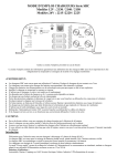
1
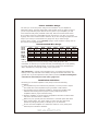
Owner's manual
Z-series
ity
l
a
u
Q
Sound S A/B
CLAS
Class A/B Sound Quality Amplifier
Before operating the unit, please read this manual throughly
and retain it for future reference.
Protect your
Investment
Note your information below for reference:
Model #
Serial #
Date Purchased
And: Register your Zapco product now
At:
www.zapco.com
Mission Statement
Committed to excellence
Zapco is dedicated to the pursuit of audio fidelity. Our prime objectives are to
design and produce audio products of unsurpassed quality, to provide
unparalleled support and service for these products, and to conduct business in a
manner that will enhance the quality of life for all involved.
Experience: Knowledge from doing
There is absolutely no substitute for experience; that is a simple fact of life.
Another simple fact is that Zapco has, for over forty years, been the leader in
defining quality standards for the car audio industry. These years of experience
have led to a thorough understanding of the challenges that are unique to the
world of car audio. Zapco's relentless quest for sonic purity consistently yields
imaginative designs that utilize the most innovative technologies. The resulting
products set the criteria by which all others in the industry are judged.
The Zapco Z-Series
The Z-Series of Zapco amplifiers is the result of our experience over the last 40
years with the technology of sound reproduction, combined with what we have
learned in consultations with the home and car audiophile communities over the
last few years about human perception of sound. We have also used a number of
studies of the human physiology to examine what an amplifier should do to make
reproduced music sound more like live music.
What did we discover? The proper combination of output devices, op-amps,
capacitors and other internal components makes a huge difference in the quality
of the sound an amplifier produces.
What we did: We set our standards for specifications and assured that all amps
would meet them. Then we used the best combination of tantalum capacitors,
NJM5532L and/or OPA2134 op-amps, and KEC and Sanken high speed output
devices to produce what we believe are the best sounding amplifiers we have
ever offered.
Read, Use, and Enjoy
Yes, please read this manual thoroughly. We wrote it to help ensure that you get
the most from your investment in your Zapco amplifier. If you find, after reading
the manual, that you still have questions please feel free to give us a call at
1(800)47-FORCE, or, drop us a note at www.zapco.com
-2-
Power and Wire Gauge
The wire you use for the power and ground connections of your amplifier is
absolutely critical. The plain simple fact is that it takes power to deliver power. If
you do not provide the proper amount of 12V power to your amplifier, you will
never reach the full power potential of the amp. Take a look at the chart below.
If you want to have any respectable amount of power for your amp, you need a
4-gauge wire to the trunk as a bare minimum. If you are running any Zapco Z-series
amp in you trunk you need at least a 2 gauge wire. If you want enough
power to drive woofers, you’re certainly going to need at least a 2-gauge wire to
the rear and zero gauge is better.
Recommended Wire Gauge
Up to
20 A
35 A
50 A
60 A
85 A
105 A
125 A
150 A
4 Ft
14
12
10
8
4
4
4
2
7 Ft
12
10
8
8
4
4
4
2
10 Ft
12
8
8
4
4
4
4
2
13 Ft
10
8
4
4
4
2
2
2
16 Ft
10
4
4
4
2
2
2
0
19 Ft
8
4
4
4
2
2
0
0
22 Ft
8
4
4
4
2
2
0
0
28 Ft
8
4
4
2
0
0
0
0
You can certainly save money by buying cheap small gauge wire, but
remember...It will cost you in power and may even damage your car by passing
too much current and causing shorts or even fires. Protect your investment in
Zapco amplifiers by using high quality, proper gauge wire.
And remember... Current in the amplifier runs in a complete circuit from the
battery to the amp and back to the battery through the chassis and frame. The
ground wire us just as important as the power input wire. Positive and Negative
connections must always use the same gauge wire.
Installation Guidelines
Mounting your Z-Series Amplifier is easy. Keep in mind the following
guidelines:
The amplifier may be mounted in any direction, on wood, metal or carpet.
The metal case of the amplifier may be grounded or left isolated.
The amplifier requires adequate ventilation. Position the amplifier with
sufficient surrounding area for proper cooling. Keep fan and vent
endplates clear for proper internal cooling.
Keep the amplifier out of the engine compartment and other locations that
may cause excessive heat or moisture.
Make sure your ground point is at the frame or a chassis point with direct
frame contact. Note: the "quiet metal" on many new cars make body
panels very bad ground points, so always try to use the frame.
Do not mount the amplifier to a subwoofer enclosure or any other place
that may have excessive vibration!
-3-
Gain Setting
Matching Your Components for Best Sound
Proper gain setting is one of the most important factors in setting up a stereo
system. Unfortunately, gain setting is quite often done wrong. Turning up the
gain of an amp is the very last thing you should ever do to a system.
An amplifier is a step up transformer. Period. Any signal you put in is boosted by a
fixed factor, whether it's music, hiss, or any other noise. A large number of
noise problems are simply a matter of improper gain settings. The goal of gain
setting is to achieve the maximum amount of musical output from the amplifier
while getting the least amount of hiss or noise from the system. Your Z-Series
amplifier accepts an extremely wide range of input levels. As little as .5 volts
on the RCAs to as much as 8 volts. The basic gain setting is very simple and
requires no special tools. Whether you have a simple system with a deck and an
amp, or a system with a deck, line driver, equalizer, crossover, and amp, the
procedure is always the same. First, hook up the system with all gain controls at
minimum (turn the gain pot fully counter-clockwise with a small screwdriver).
Then turn on the head unit and turn up the volume. If you achieve clean sound,
and, more volume than you want, you don’t need to make any adjustments.
However, if you turn up the volume and begin to hear distorted sound before it
becomes loud, you are clipping (distorting) the deck (probably a little over ¾
volume). Turn the deck down just enough to hear clean sound again, and then
move to the next component in your system. With the deck playing at “maximum
clean volume” adjust the gain of the next component to its “maximum clean
volume”. If you adjust your gains this way, always starting at the head unit and
working down the line to the amplifier, you will get the most performance out of
your amplifier(s) with the least amount of unwanted distortion and noise.
Presenting
The Zapco Z-Series Amplifiers
-4-
FEATURES
Z-150.2
Class-AB bridgeable 12V amplifier
2/1 channel bridgeable 12V amplifier
Stable into 4 ohms bridged or 2 ohms stereo load
PWM MOSFET power supply
Variable input sensitivity
18dB octave crossover slope
Variable FULL / LP / HP Electronic Crossover
0dB, 6dB, 12dB selectable bass boost
RCA Signal input and output connectors
4-way protection circuitry
(thermal / over current / speaker short / DC)
Tested voltage & THD: 14.4V & less than 0.05% THD at rated power
Operating voltage : DC10V~15.5V power input
Wired remote control (optional)
Z-400.2
Class-AB bridgeable 12V amplifier
2/1 channel bridgeable 12V amplifier
Stable into 4 ohms bridged or 2 ohms stereo load
PWM MOSFET power supply
Variable input sensitivity
18dB octave crossover slope
Variable FULL / LP / HP crossover
Variable bass boost
Signal input and output RCA connectors
Multi-way protection circuitry
(thermal / over current / speaker short / speaker DC protection)
Tested voltage & THD: 14.4V & less than 0.05% THD at rated power
Operating voltage : DC10V~15.5V power input
Wired remote control (optional)
-5-
FEATURES
Z-150.4
Class-AB bridgeable car amplifier
4/3/2 channel bridgeable car amplifier
Stable into 4 ohms bridged or 2 ohms stereo load
PWM MOSFET power supply
Variable input sensitivity
18dB octave crossover slope
Variable Full / LP / HP Crossover
Variable bass boost
RCA signal input and output connectors
4-way protection circuitry
(thermal / over current / speaker short / DC)
Tested voltage & THD: 14.4V & less than 0.05% THD at rated power
Operating voltage : DC10V~15.5V power input
Wired remote control (optional)
Z-150.6
Class-AB bridgeable car amplifier
7/6/5/3 channel bridgeable car amplifier
Stable into 4 ohms bridged or 2 ohms stereo load
PWM MOSFET power supply
Input sensitivity (gain) control variable
18dB octave crossover slope
Variable Full/LP/HP selectable crossover
(CH1/2/3/4)
Variable Full/LPF Selectable crossover (CH5/6)
Variable bass boost (CH5/6)
Variable subsonic (CH5/6)
RCA signal input connectors
4-way protection circuitry
(thermal / over current / speaker short / DC )
Tested voltage & THD: 14.4V & less than 0.05% THD at rated power
Operating voltage : DC10V~15.5V power input
Wired remote control (optional)
-6-
RCA CONNECTION
Z-150.2
Wired Remote Control
(optional)
HEAD UNIT
to INPUT of
ADDITIONAL
AMPLIFIERS
Z-400.2
GAIN
HPF
LPF
BASS
REMOTE
PWR
CH1
CH1
8V
0.2V 50Hz
500Hz
LPF
HPF
30Hz
250Hz 0dB
PRT
12dB
FULL
CH2
CH2
INPUT
OUTPUT
Wired Remote Control
(optional)
to INPUT of ADDITIONAL
AMPLIFIERS
HEAD UNIT
Connect your source unit to the amplifier using the "INPUT" RCA connectors. The "OUTPUT" connector
can be used to pass the input signal to another amplier. For Initial Setup: Always set bass boost to 0dB,
and set the amplifier gain to minimum (8V sensitivity). Remember: amp gain is not a volume control.
It is used only to match your amplifier input sensitivity to your source unit output.
-7-
RCA CONNECTION
Z-150.4
GAIN
HPF
CHANNEL 3/4
LPF
BASS
REMOTE
PWR
CH1
CH3
8V
0.2V 50Hz
GAIN
CH2
INPUT
OUTPUT
8V
500Hz
HPF
0.2V 50Hz
500Hz
HPF FULL LPF
30Hz
CHANNEL 1/2
HPF FULL LPF
250Hz 0dB
LPF
30Hz
BASS
250Hz 0dB
PRT
12dB
12dB
CH4
INPUT
Wired Remote Control
(optional)
to INPUT of ADDITIONAL
AMPLIFIERS
HEAD UNIT
Z-150.6
Wired Remote Control
(optional)
HEAD UNIT
Setup Tip: Set your amp gains to minimum (8V sensitivity) at first hook-up. Turn your head unit up to
maximum clean volume (usually about 3/4). If the system is loud enough (or even too loud), leave it
there. If not, use the gain control to get just the volume you need. This way you will have less distortion,
less noise, and more dynamic range in your music. The music will sound more like live music.
Need more bass? Now that you have matched the gains, you can adjust the bass boost if needed
-8-
POWER CONNECTION
Z-150.2
25Ax2
GROUND
to REMOTE Turn-on
from HEAD UNIT
HEAD UNIT
BATTERY
GROUND
Z-400.2 / Z-150.4
GROUND
Caution
to REMOTE Turn-on
from HEAD UNIT
This amplifier is not supplied with internal
fuse. Make sure you install an in-line
fuse holder near the +terminal of battery.
Z-400.2:Recommend 100 Ampere fuse.
Z-150.4:Recommend 80 Ampere fuse.
HEAD UNIT
BATTERY
-9-
GROUND
POWER CONNECTION
Z-150.6
GROUND
to REMOTE Turn-on
from HEAD UNIT
Caution
This amplifier is not supplied with internal
fuse. Make sure you install an in-line
fuse holder from the +terminal of battery.
Recommend 100 Ampere fuse.
HEAD UNIT
BATTERY
GROUND
+12V Power
Disconnect the Battery ground. Connect the +12V terminal of the amplifier to the + terminal of
the battery using the appropriate guage wire cable. Always use the same guage wire for Power
and Ground. Install an in-line fuse holder, within 14" of the + terminal of battery.
GROUND
Connect the GND (ground) terminal to the cars frame of chassis.
Keep this cable as short as possible and make sure that the connection with the frame or chassis is rust
free and clear of paint or grime. Any ground connection should be at the frame or a part with direct
connection to a major frame component.
REMOTE
Connect the REM terminal of the amplifier to the 12v trigger output of the source unit or a car accessory
terminal at the fuse box or ignition switch using appropriate gauge wire.
Caution
After all electrical connections are made: You may re-connect the battery ground.
Always use recommended fuse ratings. Wire must always be fused at the battery for protection
against possible damage to the vehicle. If you need to replace the power fuse, replace it with
a fuse of the same value.
-10-
SPEAKER CONNECTION
Z-150.2
1 Channel Bridged
CH1-MONO
SUBWOOFER
Speaker Impedance
4~8 ohms
2 Channel Stereo
CH2
Speaker Impedance
2~8 ohms
CH1
3 Channel Tri Mode
CH2
Speaker Impedance
2~8 ohms
X-O
Note: All Tri-Mode woofer setups
CH1
X-O
X-O
require crossovers between Woofers
and Mids-Highs to preserve minimum
impedance for amplifier stability.
CH3-MONO
SUBWOOFER
-11-
Speaker Impedance
4~8 ohms
SPEAKER CONNECTION
Z-400.2
1 Channel Bridged
GND
REM
B+
CH1
CH2
POWER INPUT
SPEAKER OUTPUTS
CH1-MONO
SUBWOOFER
CH1/2 BRIDGED
Speaker Impedance
4~8 ohms
2 Channel Stereo
GND
REM
B+
CH1
CH2
POWER INPUT
SPEAKER OUTPUTS
CH2
Speaker Impedance
2~8 ohms
CH1/2 BRIDGED
CH1
3 Channel Tri Mode
GND
REM
B+
CH1
CH2
CH2
POWER INPUT
SPEAKER OUTPUTS
Speaker Impedance
2~8 ohms
CH1/2 BRIDGED
X-O
Note:
Tri-Mode hook-up requires a
crossover to mantain minimum
impedance and amp stability
CH1
X-O
X-O
CH3-MONO
SUBWOOFER
-12-
Speaker Impedance
4~8 ohms
SPEAKER CONNECTION
Z-150.4
2 Channel Bridged
CH1
CH1
CH2
Speaker Impedance
4~8 ohms
SPEAKER OUTPUTS
CH1/2 BRIDGED
CH1
CH2
CH3
CH4
CH3/4BRIDGED
CH3
CH4
CH2
4 Channel Stereo
CH2
CH1
CH1
CH2
SPEAKER OUTPUTS
Speaker Impedance
2~8 ohms
CH1/2 BRIDGED
CH1
CH2
CH3
CH4
CH3/4BRIDGED
CH3
CH4
CH3
CH4
6 Channel Tri Mode
Hook-up with required crossovers
X-O
CH5-MONO
SUBWOOFER
X-O
CH2
X-O
CH1
CH1
CH2
SPEAKER OUTPUTS
Speaker Impedance
4~8 ohms
CH1/2 BRIDGED
CH1
CH2
CH3
CH4
CH3/4BRIDGED
CH3
CH4
CH3
CH4
X-O
CH6-MONO
SUBWOOFER
X-O
X-O
-13-
SPEAKER CONNECTION
Z-150.6
Speaker Impedance
4~8 ohms
3 Channel Mode
Speaker
2 Channel Stereo w/2 woofers
Speaker
Speaker
Speaker Impedance
4~8 ohms
CH2
SUBWOOFER
SUBWOOFER
Speaker Impedance
2~8 ohms
CH1
5 Channel Stereo
Speaker Impedance
4~8 ohms
CH4
SUBWOOFER
Speaker Impedance
2~8 ohms
CH2
CH3
Speaker Impedance
2~8 ohms
CH1
-14-
SPEAKER CONNECTION
Z-150.6
6 Channel Mode
CH6
Speaker Impedance
2~8 ohms
CH5
CH4
Speaker Impedance
2~8 ohms
CH3
CH2
Speaker Impedance
2~8 ohms
CH1
-15-
SPECIFICATIONS
Z-150.2
Rated power output
-RMS power, 4 ohms stereo ------- 150W x 2CH
-RMS power, 2 ohms stereo ------- 250W x 2CH
-RMS power, 4 ohms bridged ------ 500W x 1CH
Signal to Noise Ratio ------------------ >90dB
Low Pass Crossover ------------------- 30Hz ~ 250Hz
High Pass Crossover ------------------- 50Hz ~ 500Hz
Bass boost @ 45Hz -------------------- Selectable 0, 6dB, 12dB
Frequency Response ------------------ 10Hz ~ 30KHz (+/-1dB)
THD@RMS Watts ---------------------- 0.05%
Channel Separation ------------------- 60dB
Fuse Rating -----------------------------25A x 2
Input Sensitivity ----------------------- 200mV~8V (+/- 5%)
Dimensions (mm) --------------------- 190(W) x 60(H) x 300(L)
Z-400.2
400W x 2CH
670W x 2CH
1340W x 1CH
>90dB
50Hz ~ 500Hz
30Hz ~ 250Hz
Variable 0~12dB
10Hz ~ 30KHz (+/-1dB)
0.05%
60dB
100A(external type fuse)
200mV~8V (+/- 5%)
190(W) x 60(H) x 480(L)
Z-150.4
Rated power output
-RMS power, 4 ohms stereo -------------------------------------------- 150W x 4CH
-RMS power, 2 ohms stereo -------------------------------------------- 250W x 4CH
-RMS power, 4 ohms bridged ------------------------------------------ 540W x 2CH
Signal to Noise Ratio ------------------------------------------------------ >90dB
Low Pass Crossover ------------------------------------------------------- 50Hz ~ 500Hz
High Pass Crossover ------------------------------------------------------- 30Hz ~ 250Hz
Bass boost @ 45Hz -------------------------------------------------------- 0~12dB
Frequency Response ------------------------------------------------------- 10Hz ~ 30KHz (+/-1dB)
THD@RMS Watts ----------------------------------------------------------- 0.05%
Channel Separation -------------------------------------------------------- 60dB
Fuse Rating ---------------------------------------------------------------- 80A(external type fuse)
Input Sensitivity ----------------------------------------------------------- 200mV~8V (+/- 5%)
Dimensions (mm) --------------------------------------------------------- 190(W) x 60(H) x440(L)
Z-150.6
Rated power output
-RMS power, 4 ohms stereo -------------------------------------------- 150W x 6CH
-RMS power, 2 ohms stereo -------------------------------------------- 230W x 6CH
-RMS power, 4 ohms bridged ------------------------------------------ 450W x 6CH
Signal to Noise Ratio ------------------------------------------------------ >90dB
Low Pass Crossover -------------------------------------------------------- 50Hz ~ 500Hz
High Pass Crossover ------------------------------------------------------- 50Hz ~ 500Hz
Bass Boost @ 45Hz -------------------------------------------------------- 0~12dB (CH5/6)
Subsonic Filter ------------------------------------------------------------- 10Hz ~ 60Hz (CH5/6)
Frequency Response ------------------------------------------------------ 10Hz ~ 30KHz (+/-1dB)
THD@RMS Watts ---------------------------------------------------------- 0.05%
Channel Separation -------------------------------------------------------- 60dB
Fuse Rating ---------------------------------------------------------------- 100A(external type fuse)
Input Sensitivity ----------------------------------------------------------- 200mV~8V (+/- 5%)
Dimensions (mm) ---------------------------------------------------------- 190(W) x 60(H) x 570(L)
The above specifications shall be modified by manufacturer for improvement without prior notice.
-16-
TROUBLE SHOOTING GUIDE
This power amplifier has protection features to prevent most forms of damage.
If the unit senses excessive heat, short circuited speakers or overload, the protection indicators will
be lit and the system will be turned off. Prior to checking the wiring for any fault, you should turn all
level controls down and turn off power. If the amplifier shuts down due to excessive heat, the
protection indicators will not be lit: simply allow the amplifier to cool down.
Before removing your amplifier, refer to the list below and follow the suggested procedures.
Always test the speakers and their wires first.
AMPLIFIER IS NOT POWERED UP
Check
Check
Check
Check
if
if
if
if
at least +12V DC is present on the battery power terminal.
at least +13.8V DC is present on the remote terminal.
a good ground connection is present. Check all fuses.
the protection LED is not lit.
PROTECTION LED ILLUMINATES WHEN AMPLIFIER IS POWERED UP
Check to see if any speaker wires are short-circuited to the chassis or themselves.
Remove speaker wires and reset the amplifier. If the protection LED still comes on,
then the amplifier is at fault.
FUSE BLOWING
Check if the minimum speaker impedance is met.
Check for short-circuits on power cable and vehicle chassis.
OVERHEATING
Check if the minimum speaker impedance is met.
Check speakers for short-circuits.
Check if there is good airflow around the amplifier
SOUND TOO LOW-DISTORTED SOUND
Check
Check
Check
Check
if the input level control is set to match the output level of the source unit.
the head unit's volume.
speakers for short-circuits
if crossover frequencies have been properly set.
HIGH HISSING NOISE - ENGINE NOISE IN SPEAKERS
Check if a good ground connection is present. Most engine noises are caused by
grounding issues.
Hissing noise is most often caused by gain issues. Proper gain matching is
usually required to eliminate hissing noise.
-17-
NOTES
-18-
ARPA of America Corporation
3037 E Palm Ave Suite 101
Manteca, CA 85337
Phone: (800) 47-Force
The Zapco Z-Series is a joint venture of ARPA of America
and ARPA Italy and manufactured in Korea