1
uniden@
GRANT
40 Channel AM/SSB
Mobile CB Radio
OWNERS MANUAL
~----
-~
I'
INTRODUCTION
UNIDEN CORPORATION OF AMERICA has combined superb workmanship and
modern styling with the very latest state-of-art circuitry to bring you the GRANT
Citizens Band Trasoceiver. It has been especially designed to give you maximum
performance and reliability. Your GRANT is completely factory aligned and quality
assurance tested.
To obtain the maximum benefit and pleasure from your GRANT, please read very
carefully the contents of this manual before attempting to install or operate the
transceiver.
WARNING
The Citizens Band
(CB) Radio Service is under the jurisdiction of the Federal
Communications Commission (F .C.C.). Any adjustments or alterations which
would alter the performance of the transceiver's original F.C.C. Type
Acceptance or which would change the frequency determining method are
strictly prohibited. Replacement or substitution of Crystals, Transistors, IC,
Regulator Diodes or any other part of a unique nature, with parts other than
those recommended by us, may cause violation of the technical regulations of
Part 95 of the F.C.C.Rules or violation of Type Acceptance requirements of
Part 2 of the Rules.
ELIMINATION
OF LICENSING
The Federal Communications Commission (F.C.C.) has ruled that Citizens Band (CB)
I
. 'I
Radio Service operators no longer are required to obtain an F .C.C. license to operate
their CB equipment. In doing so, the F.C.C. also decided to permit CB station
operation without station identification.
Elimination of individual station licenses results in no lessening of the operating
privileges or responsibilities of CB users. An operator of a CB radio station is still
required to comply with the Communications Act and with the rules of CB Radio
Service.
-1-
r
---
~
f
INSTAllATION
MOBILE STATION
Plan the location
installation. Select
with the driver or
some solid face,
provided.
INSTALLATION
of the transceiver and microphone bracket before starting the
a location that is convenient for operation and does not interfere
passenger in the vehicle. The radio should be securely fastened to
using the mounting bracket and self-tapping screws which are
MOBILE STATION
ANTENNA
Since the maximum allowable power output of the transmitter is limited by the
F.C.C., the antenna is a very important factor affecting transmission distance. It is
for this reason that we strongly recommend that you install only a quality antenna in
your new citizens band system. You have just purchased a superior transceiver. Don't
diminish its performance by installing an inferior antenna.
Only a properly matched antenna system will allow maximum power transfer from
the 50-ohm transmission line to the radiating element. Your UNIDEN dealer is
qualified to assist you in the selection of the proper antenna to meet your application requirements.
For automobile installation, the whip antenna may be used with good effect. The
most efficient and practical installation is a full quarter wave whip antenna mounted
on the rear deck or fender top midway between the rear window and bumper.
A short "loaded" whip antenna is more convenient to install on you automobile,
although the efficiency is less than a full quarter wave whip antenna.
For marine installation, consult your dealer for information regarding an adequate
grounding system and prevention of electrolysis between fittings the hull and water.
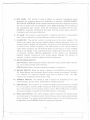
GROUND INFRMATION
Most newer U.S. and foreign made cars and small trucks use a negative ground
system, while some older cars and some newer large trucks may use a positive ground
system.
A negative ground system is generally identified by the (-) battery terminal being
connected to the vehicle motor block, but if you cannot determine the polarity
system of your vehicle, it is suggested that you consult your vehicle dealer for
definite information.
POWER CORD CONNECTION:
NEGATIVE
GROUND SYSTEM
If you are operating on a negative ground system, connect the red DC power cord
from the transceiver to the positive, or (+), battery terminal or other convenient
point and connect the black power lead to the chassis or vehicle frame, or (-) battery
terminal.
-2-
1:
-~
-
I
f
--
-..-
-,...-..---
r
POWER CORD CONNECTION:
POSITIVE GROUND SYSTEM
If you are operating on a positive ground system, connect the black DC power cord
from the transceiver to the negative, or (-), battery terminal or other convenient
point, and connect the red power lead to the chassis or vehicle frame, or (+) battery
terminal.
NOTE: With regard to the connection of the power cords, it may be possible or
desirable to connect the (red lead for negative ground system) or (black lead for
positive ground system) to the ignition switch accessory terminal so that the
transceiver is automatically turned off when the ignition switch (key) is turned off.
Alternately, the power lead may be connected to an available terminal on the fuse
block or even to a point in the wiring harness. Care must be taken, however, to guard
against a short circuit condition. When in doubt, please contact your vehicle dealer
for specific information for your vehicle.
BASE STATION OPERATION
To operate the transceiver from your home or office, using- regular house current as
the power source, you will require a separate power supply capable of supplying 3
amps at a 13.8V DC output with a nominal input voltage of 120 volts AC, 50/60Hz.
Simply connect the red (+) and black (-) leads of the transceiver to the corresponding DC terminals of the power supply.
NOTE: Do not attempt to operate this transceiver by connecting directly to 117V
AC. When an AC power supply is used with the transceiver for base station
operation any Citizens Band beam, dipole, ground plane or vertical antenna
may be used. A ground plane vertical antenna will provide the most uniform
horizontal coverage.
.
.,
I
-3-
I
~
--
-------
1
I
...
===--
--=
-
OPERATING PROCEDURE
TO RECEIVE:
The G RANT operates on 40 AM channels, 40 Upper Side Band channels and 40
Lower Side Band channels.
When you receive the SSB signal in the proper mode (USB or LSB), audio sound may
be either too high pitched or Iow pitched, indicating that your receiver may not be
tuned to the exact same frequency as the transmitter to which it is listening. The
G RANT is equipped with a Clarifier. By tuning the Clarifier, you can slightly change
the frequency of the receiver so you get a normal tone.
1. Place the PA switch in CB function - by turning SQUELCH control clockwise,
past click.
2. Turn the set on by turning the VOLUME CONTROL clockwise, past click.
NOTE: Microphone must be plugged in for receiver to operate.
3. Set the VOLUME CONTROL to a comfortable level.
4. Set the Mode Selector Switch to the desired mode.
5. Listen to the background noise from the speaker. Turn the SQUELCH CONTROL
slowly clockwise, until the noise just disappears. The Squelch is now properly
adjusted. The receiver will remain quiet until a signal is received. Do not advance
the control too far, or some of the weaker signals will not be heard.
6. Set the Channel Selector to the desired channel.
7. Adjust the CLARIFIER to clearly receive SSB or AM signals.
TO TRANSMIT:
CAUTION
The transceiver Voltage Standing Wave Ratio (V.S.W.R.) measurement must
be performed prior to the use of the transmitter. A.V.S.W.R. ratio in excess
of 2:1 may damage the transmitter.
1. Be sure the operator has read and understands part 95, F.C.C. Rules and Regulations prior to operating the transmitter.
2. Select the desired channel.
3. If the channel is clear, depress the push-to-talk switch on the microphone and
speak in a normal voice.
-4-
~
.-..---.-
..
r
1
".
"'-'
.
~-
-
-
=
I
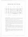
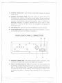
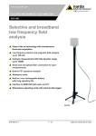
CONTROLS AND THEIR
@
VOLUME
@
(J)
SQUELCH
FUNCTIONS
@
@
-
MODNB/ANL BRITE
o"Q)
CD
@
CH9
-
0 F
.
@
GRANT
@ CID @
@
@
@
(jJ)
@
1. OFF/ON VOLUME: To turn the transceiver on, rotate this control clockwise
past click. To turn the transceiver off, rotate the control counterclockwise
click. Rotate the control clockwise for a comfortable audio level.
past
2. SQUELCH: The Squelch control is normally set to a position which eliminates
undesired background noise with no signal present. With the audio adjusted to a
satisfactory level, rotate the Squelch control clockwise to the point where the
sound from the speaker is cut off. In this position, there will be no sound from
the speaker until a signal is received. In order to hear weak signals, it may be
necessary to rotate the Squelch control counterclockwise, allowing some background noise to be heard.
>
3. PA SWITCH (on SQUELCH control): Full counterclockwise rotation of the
squelch control engages the PA function. The PA function should not be used
unless an external speaker is connected. In the squelch (or CB) position, the PA
function is disabled and the radio will transmit and receive on the selected
channel.
'!
4. MODE SELECTOR: This switch selects AM, USB, or LSB mode of operation.
This selector changes the mode of operation of both transmitter and receiver
simultaneously. Set the selector to the mode on which you wish to communicate.
-5-
~
--"'"
-
I
-
- --- -
5. MIC GAIN: This control is used to adjust, as required, microphone input
sensitivity for optimum amount of modulation in transmit. UNIDEN CORPORATION OF AMERICA citizen's band transceivers have been designed to permit
the user to attain levels of modulation up to 100% depending on the setting of
the microphone gain control, using the microphone provided with the unit.
UNIDEN's automatic compression and peak limiting circuits assure maximum
modulation with minimum distortion.
6. RF GAIN: This control is used primarily to optimize reception in strong signal
areas. Gain is reduced by counterclockwise rotation of the control.
7. CLARIFIER: The clarifier control is normally set to the center position. This
feature has several uses and can greatly enhance receiver operation. First, if a
received signal is slightly off frequency, this control can be operated as required
to optimize the receiver frequency. The effectiveness of this clarifier features
under these conditions can be observed either by listening for a more readable
signal at the speaker or by noting the S-meter reading when the clarifier control
is operated. Another effective application of this control is in eliminating
adjacent channel interference from strong signals. Operate this control, as
required, to obtain minimum adjacent channel interference.
8. METER MODE SWITCH:
SIR F Position: Meter indicates relative transmitter output power when transmiting, input signal strength when receiving.
MOD Position: Meter indicates averagepercentage of modulation.
9. NB/ANL SWITCH:When the switch is placed in the NB/ANL position, both of
RF Noise Blanker and Automatic Noise Limiter circuits are activated. The NB is
very effective for repetitive impulse noise such as ignition noise. The AN L
reduces most undesirable interference noises.
10. DIMMER SWITCH: This switch is used to adjust the brightness of the LED
channel display and the meter. DI M position reduces brightness.
11. CH9 SWITCH:
This switch
is for use when emergency
communication
is needed
on the emergency channel, CH9. Pressing the CH9 switch activates CH9 regardless of the position of the channel selector switch. When CH9 switch is pressed,
the channel display is blanked and the CH9 indicator is activated.
12. MOD-S/RF
METER:
This meter displays relative transmitter
RF output power
and percentage of modulation
when transmitting,
as well as input signal strength
when receiving. The meter is illuminated when power is on, the illumination can
be adjusted by the DIMMER Switch for optimum brightness.
-6-
T
I
J
--
13. CHANNEL INDICATOR:
number in use.
----.--.
Light Emitting Diode(LED) indicates the channel
14. CHANNEL SELECTOR KNOB: This knob selects the desired channel for
transmission and reception. All channels, except channel 9, may be used for
communications between stations. Channel 9 has been reserved by the F.C.C. for
emergency communications involving the immediate safety of individuals or
immediate protection of property. Channel 9 also may be used to render
assistance to a motorist. This is an F.C.C. rule and applies to all operators of
citizens band radios.
15. CH9 INDICATOR: Lights to show that the CH9 Switch has been activated.
16. TX/RX INDICATOR: This indicator lights red when the transmitter
tion and lights green when the receiver is in operation.
is in opera-
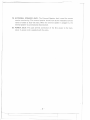
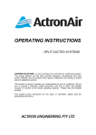
RADIO BACK PANEL CONNECTORS
@
@
@
@
@ @ @ @
[@""" '°
@] r
@
.
@
17. ANTENNA CONNECTOR: This female connector permits connection
transmission line cable male connector (PL-259) to the transceiver.
.1
I
of the
18. PUBLIC ADDRESS SPEAKER JACK: An external 8 ohm 4-watt speaker must
be connected to the PA SP jack located on the rear panel when the transceiver is
used as a public address system. The speaker should be directed away from the
microphone to prevent acoustic feedback. Physical separation or isolation of the
microphone and speaker is important when operating the PA at high output
levels.
-7-
=r=
--
I
j
-
-====
<--=====0
---
1=
19. EXTERNAL SPEAKER JACK: The External Speaker Jack is used for remote
receiver monitoring. The external speaker should have 8 ohm impedance and be
rated to handle at least 4.0 watts. When the external speaker is plugged in, the
internal speaker is automatically disconnected.
20. POWER JACK: This jack permits connection of the D.C. power to the transceiver. A power cord is supplied with the radio.
-8-
-~
T
+
-
=-- ---=
r
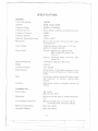
SPECIFICATIONS
GENERAL
F.C.C. Type Number
Channels
Frequency Range
Frequency Control
1005002
40AM, 40LSB, 40USB
26.965 to 27.405 MHz
Frequency Tolerance
Phase Locked Loop(PLL) synthesized circuitry.
0.005%
Frequency Stability
0.001%
Operating Temperature Range
Microphone
-20°C to +50°C
Plug-in type; dynamic with push-to-talk switch
and coiled cord.
Input Voltage
13.8V DC nominal, 15.9V max., 11.7V min.
(positive or negative ground).
Current Drain
Transmit: AM full mod., 3A maximum.
SSB, 12 watts PEP output, 3A
maximum.
Receiver: squelched; 0.5A,
output 1A.
Cabinet Dimensions
Weight
Antenna Connector
audio
7-7/8"(W) x 2-3/8"(H) x 9-1/4"(D)
5 pounds
UHF, SO-239
Semiconductors
44 transistors, 3 field effect transistors, 6 integrated circuits, 62 diodes and 3 light emitting
diodes.
Meter
Illuminated; indicates relative RF power output
and modulation on Transmit, received signal
strength.
Indicators
LED display; channel, emergency channel and
TX/RX.
TRANSMITTER
I
.
maximum
Power Output
AM,4 watts
SSB, 12 watts, P.E.P.
Modulation
High and Iow level Class B, Amplitude Modulation.
.1
I
Intermodulation
Distortion
SSB Carrier Suppression
Unwanted Sideband
SSB: 3rd and 5th order, more than -25 dB.
7th and 9th order, more than -35 dB.
More than -45 dB.
More than -45 dB.
-9-
-
..{.
..----..---.
--
-~
r
i
<:::::C
Frequency Response
AM and SSB: 350 to 2500 Hz.
Output Impedance
SSB Filter
52 ohms, unbalanced.
7.8 MHz, crystal lattice type
6 dB @2.2 kHz
60 dB @4.6 kHz
RECEIVER
Sensitivity
SSB: Less than 0.25 pV for 10 dB
(S+N)/N at greater than Y2watt of radio
output.
AM: Less than 0.5 pV for 10 dB.
(S+N)/N at greater than % watt of audio
output.
Selectivity
Cross Modulation
Image Rejection
SSB 6 dB @2.2 kHz, AM 6 dB @7.5 kHz.
More than 55 dB.
More than 60 dB.
I.F. Frequency
AM and SSB RF Gain Control
AM: 455 kHz SSB: 7.8 MHz
Automatic Gain Control
(AGC): Less than 10 dB change in audio output for inputs from 10 to 500,000 /lV.
Squelch
Noise Blanker
Adjustable; threshold less than 0.5 pV.
Clarifier Range
Audio Output Power
Adjustable for optimum signal reception.
RF type, effective on AM and SSB.
:t1.25 kHz.
3.5 watts minimum into 8 ohms.
Frequency Response
Distortion
350 to 2500 Hz.
Built-in Speaker
8 ohms, round.
8 ohms; disables internal speaker when connected.
External Speaker (Not Supplied)
Less than 10% at 3 watts output.
PA SYSTEM
-
Power Output
External Speaker for PA
.)
3.5 watts into external speaker.
8 ohms (not supplied).
- 10-
T
'-----.---.
I
--------.--
----
f
r~
SERVICING YOUR TRANSCEIVER
The technical information, diagrams and charts will be supplied upon request. It is
the user's responsibility to see that this radio is operating at all times in accordance
with the F.C.C. Citizens Radio Service regulations. We highly recommend that you
consult a qualified radiotelephone technician for the servicing and alignment of this
CB radio product.
Please refer to the WARNING information contained in the 1st page of this Owner's
Manual.
(NOTE: When ordering parts, it is essential to specify the correct model number and
serial number of the unit.)
MAINTENANCE AND ADJUSTMENT
This transceiver is especially designed for the environment encouuntered in mobile
installations. The use of all solid state circuitry and its light weight result in high
reliability. Should failure occur, however, replace parts only with identical parts. Do
not substitute.
PREVENTIVE
At
1.
2.
3.
4.
MAINTENANCE
six to twelve month intervals, the following system checks should be made:
Check Standing Wave Ratio (SWR).
Inspect all electrical connections to ensure that they are tight.
Inspect antenna coaxial cable for wear or breaks on shielding.
Inspect all screws and other mounting hardware for tightness.
ADJUSTMENT
This transceiver is factory aligned and should not require any adjustment when used
with a 52 ohm antenna. If an antenna other than 52 ohm impedance is used,
adjustment of the transmitter output circuit may be made to obtain optimum power
transfer to the antenna. This adjustment should be made only by a licensed technician using a high quality in-line RF wattmeter which will not produce standing waves
when inserted in the antenna cable.
- 11 -
===r
r
1
.---r
OPERATOR TROUBLESHOOTING
Should be unit malfunction or not perform properly, the operator should perform
the procedures il.dicated below:
1. If the transceiver is completely inoperative.
* Check the power cord and fuse.
2. If trouble is experienced with receiving.
* Check ON/OFF VOLUMECONTROLsetting.
* Be sure SQUELCH is adjusted properly. Is the radio over-squelched?
* Check to see that the radio is switched to an operational mode.
3. If trouble is experienced with transmitting.
* Check to see that the transmission line (coaxial cable) is securely connected to
the ANTENNA CONNECTOR.
* Be sure that the antenna is fully extended for proper operation.
* Be sure that all transmission line (coaxial cable) connections are secure and free
of corrosion.
-12-
1:
r
t
-==:::
r=-
NOTES
-13
I
-
--
-.-------
--
-----
r
f
,
'--'==
-
r
NOTES
I
.
.)
-14
-
-~
r
f
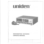
CIRCUIT DIAGR~M
FOR GRANT
[I
r.c.- "".,
I TR' ZSCI615L
!
L~
!..
'
~--------------------------------------------------------------------------TRZZ$CI615LTR! ZSCI13OL 1ROZSC94- TR5ZSC94- TR6ZSC90SAQ
TRT2SA"3PTReZSC94SAO
TR9ZSCl615L
FET1 !S"SB
TRIO
ZSC.OSAO
,,-
I
=
l_-;__-;;;..;
~
~'
.
,
..~
~~~fi]
t:-"lil
F
I~
I
:1
1
I
I
L
~J~
I
.
,'.'
,
:,
-a
.
:,
I
I
~
,. ""'TAo<'
A",.,,"'",.O-
"LUES
U"""
OTH""'"
NOTEO
"'",,0
OH.. .' .,.
OH. 1
RE""OR .ATT..ES
A" ",.
UN""
OTH""'"
'P"""O.
A. """"'AO<'
"LUES A" ,NO.:ATEO ,.
,
---- -- --- ----- --
---
J
.",
, UNLESS
OTE'.", 'P""""
,p, .'CRO -."""'A""
A "-L """"OR'
TE.P,,""""
CHARACTE""'CS A" TO UN"SS
OTHE"""
NOT'O.
BLOCK DIAGRAM FOR GRANT
r
~
I
I
I
,
I
I
I
I
z
'"
~
DIMMER
~-t:
I ~:i
u
I
I
--
I
I
I
..J
ANT
I
I
I
I
I
I
I
I
I
I
I
I
I
I
I
,-+
r--
--1
~--I'
i
I
L_d'-°~
n
-
+ - -t
I
g
~
~
t:.
u;
-
I
I
J
-
I,I!
-+-_.J
---~
I
:
~
I
5;
...
)(
...,
1
-
DC 13.8V
,.
~'"
-- -RX
TX
Printed in Taiwan
-
---===
r~
I
~
uniden
TWO-YEAR
WARRANTOR.
UNIDEN
CORPORATION
LIMITED WARRANTY
OF AMERICA
("UNIDEN")
ELEMENTS OF WARRANTY. UNIDEN warrants, for the duration of this warranty, its UNIDEN CB
Product to be free from defects in materials and craftsmanship with only the limitation or exclusions
set out below.
WARRANTY DURATION. This Warranty shall terminate and be of no further effect Two (2) years
after the date of original purchase of the Product or at the time the Product is (a) damaged or not
maintained as reasonable and necessary, (b) modified, (c) improperly installed, (d) is repaired by
someone other than Warrantor for a defect or malfunction covered by this Warranty, or (e) used in a
manner or purpose for which the Product was not intended.
PARTS COVERED.
This Warranty covers all components
of the Products.
STATEMENT OF REMEDY. In the event that the Product does not conform to this Warranty at any
time while this Warranty is effective, Warrantor will repair the defect and return it to you prepaid,
without charge for parts, service, or any other costs incurred by Warrantor or its representatives
in
connection with the performance
of this Warranty. In addition, if the Product contains a defect or
malfunction which is not repaired after a reasonable number of attempts by Warrantor to repair the
Product, the Product or defective component will, at your election, either be replaced without charge
or the purchase price for the Product will be refunded when the defective Product is delivered to
Warrantor free and clear of all liens and encumbrances.
Please note that while the Product will be
remedied under this Warranty without charge.
THIS WARRANTY
DOES NOT COVER OR PROVIDE
FOR THE REIMBURSEMENT
OR
PAYMENT OF INCIDENTAL OR CONSEQUENTIAL
DAMAGES.
Some states do not allow this exclusion or limitation
above limitation or exclusion may not apply to you.
of incidental
or consequential
damages,
so the
WARRANTY
REGISTRATION
CARD. In order to facilitate the servicing of this Warranty by
Warrantor, the Warranty Registration Card should be returned to Warrantor. However, return of the
Warranty Registration Card is not a precondition of this Warranty, and this Warranty will be observed
by Warrantor whether or not the Warranty Registration Card is returned, on the condition that other
satisfactory evidence of the date of the original purchase is provided by Warrantor.
PROCEDURE FOR OBTAINING PERFORMANCE
OF WARRANTY. In the event that the Product
does not conform to this Warranty, the Product should be sh ipped prepaid to Warrantor.
TH E
ORIGINAL OR A COpy OF THE SALES RECEIPTOR OTHER VALID EVIDENCE OF THE DATE
OF THE ORIGINAL PURCHASE MUST ACCOMPANY THIS PRODUCT.
LEGAL REMEDIES. This Warranty gives you specific legal rights, and you may also have other rights
which vary from state to state.
This warranty
is void outside
the United States of America.
I
I
. 'i
uniden@
CORPORATION OF AMERICA
Personal Communications Division
4700 Amon Carter Boulevard
Fort Worth, Texas 76155
U TU DO 151 OZD
=r
@1983 Uniden Corporation of America
:J
---
Printed in Taiwan
I
---i